

Page 1
PROFESSIONAL VIDEO MONITOR
BVM-F250
BVM-F170
付属の CD-ROM には、BVM-F250/F170 のオペレーションマニュアル(日本語、英語、フランス語、ドイツ語、
イタリア語、スペイン語、中国語(簡体字)、中国語(繁体字)、韓国語)が記録されています。詳しくは、「CDROMマニュアルの使いかた」(4 ページ)をご覧ください。
The supplied CD-ROM includes the Operation Manual for the BVM-F250/F170 (English, French, German,
Italian, Spanish, Simplified Chinese, Traditional Chinese, Korean, and Japanese versions). For more
details, see
“Using the CD-ROM Manual” on page 58.
電気製品は、安全のための注意事項を守らないと、
火災や人身事故になることがあります。
このオペレーションガイドには、事故を防ぐための重要な注意事項と製品の取
り扱いかたを示してあります。このオペレーションガイドをよくお読みのうえ、
製品を安全にお使いください。お読みになったあとは、いつでも見られるとこ
ろに必ず保管してください。
OPERATION GUIDE [Japanese/English]
1st Edition
Page 2
日本語
安全のために
電気製品は、安全のための注意事項を守らないと、火災や感電などにより死亡や大
けがなど人身事故につながることがあり、危険です。
事故を防ぐために次のことを必ずお守りください。
安全のための注意事項を守る
5 〜 8 ページの注意事項をよくお読みください。製品全般の安全上の注意事項が記
されています。9 〜 10 ページの「使用上のご注意」もあわせてお読みください。
定期点検をする
5 年に 1 度は、内部の点検を、お買い上げ店またはソニーのサービス窓口にご依頼
ください(有料)。
故障したら使わない
すぐに、お買い上げ店またはソニーのサービス窓口にご連絡ください。
万一、異常が起きたら
• 異常な音、におい、煙が出たら
• 内部に水、異物が入ったら
• モニターを落としたり、キャビネットを破損したときは
警告表示の意味
このオペレーションガイドおよび
製品では、次のような表示をして
います。表示の内容をよく理解し
てから本文をお読みください。
この表示の注意事項を守らないと、
火災や感電などにより死亡や大け
がなど人身事故につながることが
あります。
この表示の注意事項を守らないと、
感電やその他の事故によりけがを
したり周辺の物品に損害を与えた
りすることがあります。
注意を促す記号
m
a 電源を切る。
b 電源コードや接続ケーブルを抜く。
c お買い上げ店またはソニーのサービス窓口に連絡する。
行為を禁止する記号
行為を指示する記号
2
安全のために
Page 3
目次
CD-ROMマニュアルの使いかた ........................................... 4
準備 ........................................................................................................................... 4
CD-ROMマニュアルを読むには........................................................4
警告...................................................................................... 5
注意...................................................................................... 6
その他の安全上のご注意 .......................................................... 8
使用上のご注意(性能を保持するために)............................. 9
ソフトウェアバージョン 1.1、1.2 でサポートされた
機能 ................................................................................ 11
特長.......................................................................................... 12
別売品 ...................................................................................... 14
入出力端子と入力アダプター ............................................... 16
各部の名称と働き(BVM-F250)....................................... 17
前面パネル.........................................................................................................17
後面/左側面パネル ...................................................................................19
各部の名称と働き(BVM-F170)....................................... 21
前面パネル.........................................................................................................21
後面パネル.........................................................................................................23
設置環境 .................................................................................. 25
入力アダプターについて ....................................................... 25
入力アダプターの取り付け(BVM-F250)....................... 26
入力アダプターの取り付け(BVM-F170)....................... 27
転倒防止ブラケットの取り付け(BVM-F250)................ 29
ラックへの取り付け(BVM-F170)................................... 30
接続(BVM-F250).............................................................. 30
コントローラー(BKM-16R)を接続する.................................31
LAN を使って複数台を接続する......................................................31
接続(BVM-F170).............................................................. 32
コントローラー(BKM-16R)を接続する.................................33
LAN を使って複数台を接続する......................................................33
電源の投入(BVM-F250).................................................. 34
電源コードを接続する..............................................................................34
モニターの電源を入れる ........................................................................35
電源の投入(BVM-F170).................................................. 35
電源に接続する..............................................................................................35
モニターの電源を入れる ........................................................................36
使用地域の設定 ...................................................................... 36
メニューリスト ...................................................................... 39
仕様(BVM-F250).............................................................. 45
仕様(BVM-F170).............................................................. 47
外形寸法図(BVM-F250).................................................. 49
外形寸法図(BVM-F170).................................................. 51
JP
この説明書の読みかた
このオペレーションガイドは、BVM-F250 と BVM-F170
について記載しています。
2 機種で異なる項目には機種名を表示してあります。
(例:各部の名称(BVM-F250)など)
機種名が表示してない項目は、2 機種の共通の内容とし
てお読みください。
目次
3
Page 4

CD-ROMマニュアルの使
いかた
付属の CD-ROMには、本機のオペレーションマニュアル
(日本語、英語、フランス語、ドイツ語、イタリア語、スペ
イン語、中国語(簡体字)、中国語(繁体字)、韓国語)が
PDF形式で記録されています。
準備
付属の CD-ROMに収納されているオペレーションマニュア
ルをご覧いただくためには、以下のソフトウェアがコン
ピューターにインストールされている必要があります。
• AdobeReader6.0以上
メモ
AdobeReaderがインストールされていない場合は、下記
URLよりダウンロードできます。
http://www.adobe.co.jp/products/acrobat/readstep2.html
ご注意
CD-ROMの破損または紛失により新しい CD-ROMをご希
望の場合は、ソニーのサービス担当者にご依頼ください
(有料)。
Adobe、および AdobeReaderは AdobeSystemsIncorporated(アドビシス
テムズ社)の商標です。
CD-ROMマニュアルを読むには
CD-ROMに入っているオペレーションマニュアルを読むに
は、次のようにします。
1
CD-ROMを CD-ROMドライブに入れる。
表紙ページが自動的にブラウザで表示されます。
ブラウザで自動的に表示されないときは、CD-ROMに
入っている index.htmファイルをダブルクリックして
ください。
2
読みたいオペレーションマニュアルを選択してクリッ
クする。
オペレーションマニュアルの PDFファイルが開きま
す。
メモ
AdobeReaderのバージョンによっては、ファイルが正しく
表示されないことがあります。
正しく表示されない場合は、上記「準備」の項の URLより
最新のソフトウェアをダウンロードしてお使いください。
CD-ROMマニュアルの使いかた
4
Page 5
警告
指定の電源電圧で使う
取扱説明書に記されている電源電圧でお
使いください。
規定外の電源電圧での使用は、火災や感
電の原因となります。
油煙、湯気、湿気、ほこりの
多い場所では設置・使用しな
い
内部を開けない
内部には電圧の高い部分があり、キャビ
ネットや裏ぶたを開けたり、改造したり
すると、火災や感電の原因となることが
あります。内部の調整や設定、点検、修
理は、お買い上げ店またはソニーのサー
ビス窓口にご依頼ください。
内部に水や異物を入れない
水や異物が入ると火災や感電の原因とな
ります。
万一、水や異物が入ったときは、すぐに
電源を切り、電源コードや接続ケーブル
を抜いて、お買い上げ店またはソニーの
サービス窓口にご相談ください。
電源コードを傷つけない
電源コードを傷つけると、火災や感電の
原因となることがあります。
• 設置時に、製品と壁やラック、棚など
の間に、はさみ込まない。
• 電源コードを加工したり、傷つけたり
しない。
• 重いものをのせたり、引っ張ったりし
ない。
• 熱器具に近づけたり、加熱したりしな
い。
• 電源コードを抜くときは、必ずプラグ
を持って抜く。
万一、電源コードが傷んだら、お買い上
げ店またはソニーのサービス窓口に交換
をご依頼ください。
上記のような場所に設置すると、火災や
感電の原因となります。
取扱説明書に記されている仕様条件以外
の環境での使用は、火災や感電の原因と
なります。
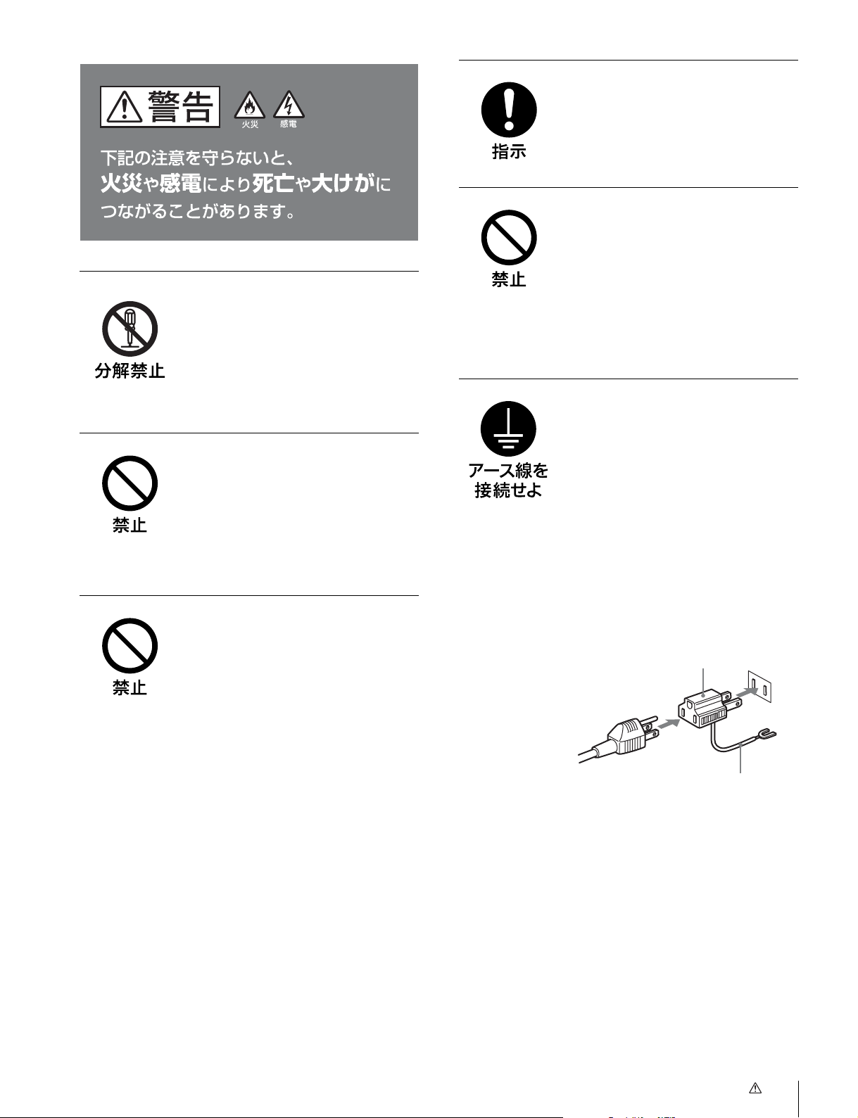
安全アースを接続する
安全アースを接続しないと、感電の原因
となることがあります。
次の方法でアースを接続してください。
• 電源コンセントが 3 極の場合
付属の電源コードを使用することで安
全アースが接続されます。
• 電源コンセントが 2 極の場合
付属の 3 極 t2 極変換プラグを使用
し、変換プラグから出ている緑色の
アース線を建物に備えられているアー
ス端子に接続してください。
変換プラグアダプター
アース線
安全アースを取り付けることができない
場合は、お買い上げ店またはソニーの
サービス窓口にご相談ください。
警告
5
Page 6
注意
指定された電源コード、接続
ケーブルを使う
付属の、あるいは取扱説明書に記されて
いる電源コード、接続ケーブルを使わな
いと、感電や故障の原因となることがあ
ります。
他の電源コードや接続ケーブルを使用す
る場合は、お買い上げ店またはソニーの
サービス窓口にご相談ください。
通気孔をふさがない
ぬれた手で電源プラグをさわ
らない
ぬれた手で電源プラグを抜き差しする
と、感電の原因となることがあります。
転倒、移動防止の処置をする
モニターをラックに取り付け・取りはず
しするときは、転倒・移動防止の処置を
しないと、倒れたり、動いたりして、け
がの原因となることがあります。
安定した姿勢で注意深く作業してくださ
い。
また、ラックの設置状況、強度を充分に
お確かめください。
製品の上に乗らない、重いも
のを載せない
倒れたり、落ちたり、壊れたりして、け
がの原因となることがあります。
通気孔をふさぐと内部に熱がこもり、火
災や故障の原因となることがあります。
風通しをよくするために次の項目をお守
りください。
• 壁から 10cm 以上離して設置する。
• 密閉された狭い場所に押し込めない。
• 毛足の長い敷物(じゅうたんや布団な
ど)の上に設置しない。
• 布などで包まない。
• あお向けや横倒し、逆さまにしない。
不安定な場所に設置しない
ぐらついた台の上や傾いたところなどに
設置すると、モニターが落ちたり、倒れ
たりして、けがの原因となることがあり
ます。また、設置・取り付け場所の強度
を充分にお確かめください。
直射日光の当たる場所や熱器
具の近くに設置・保管しない
内部の温度が上がり、火災や故障の原因
となることがあります。
お手入れの際は、電源を切っ
て電源プラグを抜く
電源を接続したままお手入れをすると、
感電の原因となることがあります。
接続の際は電源を切る
電源コードや接続ケーブルを接続すると
きは、電源を切ってください。感電や故
障の原因となることがあります。
移動の際は電源コードや接続
コードを抜く
コード類を接続したまま本機を移動させ
ると、コードに傷がついて火災や感電の
原因となることがあります。
6
注意
Page 7
定期的に内部の掃除を依頼す
る
密閉環境に設置する際は注意
する
長い間掃除をしないと内部にホコリがた
まり、火災や感電の原因となることがあ
ります。1 年に 1 度は、内部の掃除をお
買い上げ店またはソニーのサービス窓口
にご依頼ください(有料)。
特に、湿気の多くなる梅雨の前に掃除を
すると、より効果的です。
入力アダプターおよびコント
ロールユニットを取り付ける
際には電源を切って電源プラ
グを抜く
モニターを電源に接続したまま各種入力
アダプターおよびコントロールユニット
の取り付けを行うと、感電の原因になる
ことがあります。入力アダプターおよび
コントロールユニットの取り付けの際に
はモニターの電源を切り、電源プラグを
抜いてください。
入力アダプターなどの取り付
け、取りはずしは注意深く
本機をラックやモニター棚に収納した
際、上下および周辺の機器によりモニ
ター周辺の通気孔が妨げられ動作温度が
上がり、故障や発熱の原因となる可能性
があります。本機の動作条件温度 0 ℃か
ら 35 ℃を保つように上下に 1U の隙間
をあけ、また周辺機器との隙間を充分に
とり、通気孔の確保や通気ファンの設置
などの配慮をしてください。
設置は専門の工事業者に依頼
する
設置については、必ずソニーのサービス
担当者または営業窓口にご相談くださ
い。
壁面や天井などへの設置は、本機と取り
付け金具を含む重量に充分耐えられる強
度があることをお確かめください。充分
な強度がないと、落下して、大けがの原
因となります。
また、一年に一度は、取り付けがゆるん
でないことを点検してください。
各種入力アダプターや、コントローラー
アタッチメントスタンドの取り付け、取
りはずしの際に部品や基板の角などで手
や指にけがをすることがあります。保護
手袋などをして注意深く作業してくださ
い。
コード類は正しく配置する
電源コードや接続ケーブルは、足に引っ
かけると本機の落下や転倒などによりけ
がの原因となることがあります。
十分注意して接続・配置してください。
電源コードのプラグおよびコ
ネクターは突き当たるまで差
し込む
真っ直ぐに突き当たるまでさしこまない
と、火災や感電の原因となります。
BVM-F170のみ
DCIN端子に規格以外の入力
電圧をかけない
DCIN 端子に規格以外の入力電圧をかけ
ると火災や感電の原因となることがあり
ます。
指定された方法でラックマウ
ントする
本機をラックに取り付ける際には付属の
ブラケットを使用し取扱説明書に記載さ
れた方法で取り付けてください。
指定された以外の方法でラックマウント
すると落下してケガや損害の原因となる
ことがあります。
注意
7
Page 8
指定以外の機器には使用しな
い
付属のラックマウントブラケットは本機
専用です。指定以外の機器に使用すると
搭載した機器が落下してケガの原因にな
ることがあります。
組み立て・取り付けは注意深
く
付属のラックマウントブラケットを使用
する際、または前面保護板の着脱の際に
は部品のかどやエッジで手や指にけがを
しないように注意深く作業してくださ
い。
作業の際には保護手袋を着用することを
おすすめします。
その他の安全上のご注意
BVM-F250
本機の電源スイッチは、左側面に備えられています。
設置の際には、電源スイッチに容易にアクセスできるよう
にしてください。
機器を水滴のかかる場所に置かないでください。また水の
入った物、花瓶などを機器の上に置かないでください。
注意
付属の電源コードは本機の専用品です。
他の機器には使用できません。
BVM-F170
警告
設置の際には、容易にアクセスできる固定配線内に専用遮
断装置を設けるか、使用中に、容易に抜き差しできる、機
器に近いコンセントに電源プラグを接続してください。
万一、異常が起きた際には、専用遮断装置を切るか、電源
プラグを抜いてください。
機器を水滴のかかる場所に置かないでください。また水の
入った物、花瓶などを機器の上に置かないでください。
注意
付属の電源コードは本機の専用品です。
他の機器には使用できません。
その他の安全上のご注意
8
Page 9

使用上のご注意(性能を保持する
ために)
画面について
• 画面を太陽にむけたままにすると、画面を傷めてしまい
ます。窓際や室外に置くときなどはご注意ください。
• 画面を強く押したり、ひっかいたり、上にものを置いた
りしないでください。画面にムラが出たり、パネルの故
障の原因になります。
• 使用中に画面やキャビネットがあたたかくなることがあ
りますが、故障ではありません。
焼き付きについて
一般に、有機 EL パネルは、その高精細な画像を得るため
に採用している材料の特性上、焼き付きが起こることがあ
ります。画面内の同じ位置に変化しない画像の表示を続け
たり、くり返し表示したりすると、焼き付いた画面を元に
戻せなくなります。
特に、アスペクト変更などで表示エリアよりも狭いサイズ
で表示し続けた場合、パネル劣化の進行が早まるおそれが
あります。
静止画などの長時間連続表示、または密閉された空間や空
調機器の吹き出し口付近など高温多湿環境下における連続
運用を避けてください。
モニター使用時に輝度を少し下げたり、モニター未使用時
に電源を切ったりするなどして、上記のような現象を未然
に防ぐことをおすすめします。
輝点・滅点について
本機のパネルは有効画素 99.99%以上の非常に精密度の高い
技術で作られていますが、画面上に黒い点が現れたり(画
素欠け)、常時点灯している輝点(赤、青、緑など)や滅点
がある場合があります。また、パネルの特性上、長期間ご
使用の間に画素欠けが生じることもあります。これらの現
象は故障ではありませんので、ご了承の上本機をお使いく
ださい。
画面の取り扱いとお手入れについて
長時間の表示で焼き付きが発生しやすい画像
• 画面縦横比 16:9 以外のマスク処理された画像
• カラーバーや長時間静止した画像
• 設定や動作状態を示す文字やメッセージなどの表示
• センターマーカー、セーフエリアマーカーなどの表示
焼き付きを軽減するには
• 文字表示やマーカー表示を消す
MENU ボタンを押して、文字表示を消します。接続した
機器の文字表示やマーカー表示を消すには、接続した機
器を操作してください。詳しくは、接続した機器の取扱
説明書をご覧ください。
• 電源をこまめに切る
長時間使用しないときは、電源を切ってください。
スクリーンセーバーについて
本機には、焼き付きを軽減するためのスクリーンセーバー
機能が内蔵されています。ほぼ静止した画像を表示したま
ま 10 分以上経過すると、自動的にこの機能が働き、画面の
輝度を下げます。
長時間の使用について
固定された画像または静止画などの長時間連続表示や、高
温環境下で連続運用した場合、有機 EL パネルの構造上お
よび材料の特性上、残像や焼き付き、しみ、すじ、輝度低
下などを発生することがあります。
画面には、反射による映りこみを抑えるため、特殊な表面
処理を施しています。誤ったお手入れをした場合、性能を
損なうことがありますので、次のことを必ずお守りくださ
い。また、画面は傷つきやすいので固い物などでこすった
り、たたいたり、物をぶつけたりしないでください。
• お手入れをする前に、必ず電源プラグをコンセントから
抜いてください。
• 画面には特殊な表面処理をしているので、シールなどの
粘着物は絶対に貼らないでください。
• 画面には特殊な表面処理をしているので、なるべく直接
手で触れないようにしてください。
• 画面の汚れは、クリーニングクロスなどの乾いた柔らか
い布でそっと拭いてください。
• 画面の汚れがひどいときは、クリーニングクロスやメガ
ネ拭きなどの柔らかい布に、水で薄めた中性洗剤を少し
含ませて軽く拭いてください。
• クリーニングクロスにゴミなどが付着したまま強く拭く
と、画面に傷が付くことがあります。
• アルコールやベンジン、シンナー、酸性洗浄液、アルカ
リ性洗浄液、研磨剤入り洗浄液、化学ぞうきんなどは、
画面を傷めますので絶対に使用しないでください。
• 画面の表面からほこりを取り除くときは、ブロアーをお
使いください。
使用上のご注意(性能を保持するために)
9
Page 10

結露
本機を寒い場所から暖かい場所に急に移動したり、湿度の
高い部屋で使用したりすると、空気中の水分が水滴となっ
て製品内部に付着することがあります。この現象を結露と
いいます。
本機には結露を警告するランプなどは備えていません。外
筐に水滴が付着したときは、電源を切り、結露が解消する
まで待ってから使用してください。
設置について(BVM-F250)
設置時には、通気やサービス性を考慮して設置スペースを
確保してください。
• ファンの排気部や通気孔をふさがない。
• 通気のためにセット周辺に空間をあける。
• 作業エリアを確保するため、セット後方は、40cm 以上の
空間をあける。
机上などの平面に設置する場合は、上下に 1U(4.4cm)以
上の空間をそれぞれ確保してください。なお、セット上部
はサービス性を考慮し 40cm 以上の空間を確保することを
推奨します。
設置について(BVM-F170)
本機をラックに設置するときは、ラックと本機の間に、上
下に1 U(4.4cm)、左右に 1.0cm 以上の空間を確保してく
ださい。
廃棄するときは
一般の廃棄物と一緒にしないでください。
ごみ廃棄場で処分されるごみの中にモニターを捨てないで
ください。
使用済みのモニターは、国または地域の法令に従って廃棄
してください。
ファンエラーについて
本機には冷却用ファンが内蔵されています。前面パネルの
OPERATE ランプが赤で点滅し、OVERRANGE ランプが
アンバーで点滅、ECO ランプがマゼンタで点灯した場合
(ファンエラー警告)は、電源を切り、お買い上げ店または
ソニーのサービス窓口にご連絡ください。
使用上のご注意(性能を保持するために)
10
Page 11
ソフトウェアバージョン 1.1、1.2 でサポートされた機
能
BVM-F250/F170 のソフトウェアバージョン 1.1および 1.2
では、以下の機能が新たにサポートされています。
ソフトウェアバージョン 1.1
メニュー名 サポートされた機能
1)
・Auto
(Adjustment メニューの ColorTempAdj メニュー内 )
・CopyFrom
(Adjustment メニューの PictureAdj メニュー内)
(Adjustment メニューの ColorTempAdj メニュー内)
(ChannelConfiguration メニュー内)
(FunctionSetting メニューの MarkerSetting メニュー内)
(FileManagement メニュー内)
・DisplayPort
(ChannelConfiguration メニューの Format メニュー内)
(ChannelConfiguration メニューの RGBRange メニュー内)
・ HDMI/DisplayPortAuto
(ChannelConfiguration メニューの Matrix メニュー内)
(ChannelConfiguration メニューの RGBRange メニュー内)
・ HDMI/DPStatus
(SystemStatus メニュー内)
・ OverRange
(SystemConfiguration メニューの OnScreenSet メニュー内)
・ SaveTo
(FileManagement メニュー内)
・ Delete
(FileManagement メニュー内)
2)
2)
2)
内蔵のカラーセンサーを使用して色温度を自動調整する。
モニター内のデータや、他のモニターのデータ、メモリース
ティック内のデータをコピーする。
DisplayPort 信号の設定をする。
HDMI 信号または DisplayPort 信号のマトリックスの切り換え
(Matrix)、量子化レンジの設定(RGBRange)をする。
HDMI 信号または DisplayPort 信号の信号情報を表示する。
内部信号処理回路のオーバーレンジ箇所にゼブラパターンを表示
する。
システムデータをメモリースティックに保存する。
メモリースティックのファイルを削除する。
1)この機能は BVM-F170 のみに搭載されています。
2)この機能を使用するには、コントローラーのソフトウェアバージョンが 1.6 以降のものをお使いください。
ソフトウェアバージョン 1.2
メニュー名/部品名 サポートされた機能
・ ECO ランプ 本機の消費電力の状態を点灯色で表示する。
・ DisplayPortUpgrade
(SystemConfiguration メニューの MonitorUpgrade メニュー内)
・ コントローラーの ENTER ボタン
3)この機能を使用するには、コントローラーのソフトウェアバージョンが 1.7 以降のものをお使いください。
3)
DisplayPort データをアップグレードする。
コントローラーのファンクションボタンに割り当てた機能を一括
表示する。
ソフトウェアバージョン 1.1、1.2 でサポートされた機能
11
Page 12

特長
プロフェッショナルビデオモニター BVM-F250 は 25 型、
BVM-F170 は 16.5 型の高性能カラービデオモニターです。
正確な画像表示を要求される放送局やビデオプロダクショ
ンでの使用に適しています。
BVM-F250/F170 では、有機 EL パネルの長所を取り入れつ
つ、パネルの個性によって生じる見えかたの違いを抑え、
業務用モニターに求められる 3 要素、「正確な色」、「正確な
画像」、「高い信頼性」を極める技術「TRIMASTER
ライマスター)」を搭載しています。広色域デバイスを使用
したカラーマネジメントシステム、高解像度/高階調表示、
高精度の信号処理、パネル補正機能により、マスターモニ
ターに求められる高画質と信頼性を実現しています。
1) TRIMASTER は、ソニー株式会社の商標です。
新開発の有機 EL パネル搭載
有機 EL パネルは、電流を流すと光る性質を持つ有機材料
を用いています。有機材料が自ら発光する自発光型パネル
で、流す電流量により発光の強さをコントロールします。
以下の 3 つの特長があります。
優れた動画応答:
有機 EL パネルは、有機材料に流す電流を変化させると、
瞬時に発光状態が変化します。このため、優れた動画応答
性を実現でき、動画のぶれや残像の少ない映像を表現でき
ます。
また、環境温度に左右されないため、屋外での撮影などで
も変わらない性能を発揮します。
高コントラストと広いダイナミックレンジ:
黒レベルの信号が入力されるとまったく発光しないため、
真の黒を表現できます。広いダイナミックレンジにより、
イルミネーションが輝く夜景、星空、宝石やグラスなどが
輝いた瞬間など、さまざまな質感を豊かに表現できます。
豊かな色再現性:
自発光のため、ほぼすべての信号レベルにおいて色が深く、
鮮やかな映像を再現できます。
ソニー独自のスーパートップエミッション
2)
ル採用
ソニー独自のスーパートップエミッション構造の 25 型
(BVM-F250)または 16.5 型(BVM-F170)フル HD(1920
× 1080)有機 EL パネルを採用。有機 EL パネルの上面から
光を取り出す構造、および TFT などの遮蔽物がない高開口
率の実現により、高輝度で画像を表示できます。
1)
(ト
有機 EL パネ
マイクロキャビティ構造では光が有機層で何度も反射する
光共振効果によって色純度を高め、さらにカラーフィル
ターでより深い赤、緑、青の表現を可能にしました。
10 ビットパネルドライバーは高階調表現を可能にし、深い
色をさらに暗部から明るいところまで細やかに表現します。
2)「SUPERTOPEMISSION」は、ソニー株式会社の有機 EL 技術を表す商
標です。
12 ビット精度の業務用ディスプレイエンジン搭載
業務用モニター向けに独自に開発した信号処理エンジンで
す。12 ビットの信号出力精度をもち、I/P 変換処理、ス
ケーリング処理、パネルドライブなどを行っています。ま
た高精度のカラーマネージメントシステムを実装していま
す。
マルチカラースペース対応
ソニー独自の広色域有機 EL パネルと独自の 3DLUT
(LookUpTable)を使用したカラーマネージメントシステ
ムにより、放送規格 ITU-RBT.709、EBU、SMPTE-C の色
域を正確に再現します。また、より広色域のデジタルシネ
マ向けの色域
3) SMPTERP431-2 の色域を参照していますが、RGB 色度点は完全には包含
されません。
3)
にも対応しています。
高精度 I/P 変換処理
細分化されたブロック単位で画像の特徴を検出し、最適な
処理をすることで、原画に忠実でジャギーや変換エラーを
抑えた高画質を実現します。
過去の映像信号から動画・静止画の判別を行うことで、信
号遅延を抑えた動き適応処理を実現しています。
インターレース表示モード
インターレース信号を I/P 変換処理を通さず、黒のライン
を挿入することでインターレース画像として表示すること
ができます。より本来の信号方式に忠実で、CRT のような
質感のある画像が得られます。
◆ 表示の設定については、オペレーションマニュアルの「画像表
示モードを選ぶ」をご覧ください。
多様な信号フォーマットに対応
720 × 576/50iから 1920 × 1080/50P、60P まで、さらに
1920 × 1080 までの各種コンピューター信号まで多様な入力
信号に対応します。インターフェースには、標準入力とし
4)
て 3G/HD/SD-SDI、HDMI
および DisplayPort5)(HDCP
対応)信号入力を装備しています。また、4 つの入力オプ
ションポートを装備しており、別売の入力オプションボー
ドを組み合わせて、3G-SDI、HD-SDI、SD-SDI 入力を拡張
したり、デュアルリンク HD-SDI、RGB、YPbPr、Y/C、コ
ンポジット信号入力に対応します。
4) HDMI、HDMI ロゴ、および High-DefinitionMultimediaInterface は、
HDMILicensing,LLC の商標または登録商標です。
5) DisplayPort、DisplayPort ロゴ、VESA は、VideoElectronicsStandards
Association の商標または登録商標です。
12
特長
Page 13

HD フレームキャプチャー機能
3G/HD-SDI 入力のフレームをキャプチャーし、画像ファイ
6)
ルとしてメモリースティックに保存
することができ
ます。二画面表示(ピクチャーアンドピクチャー)機能を
使って過去に撮影したシーンとの色のトーン合わせや画角
確認に使用できます。
◆ 操作については、オペレーションマニュアルの「HD 信号の画
像をキャプチャーする(HD フレームキャプチャー)」をご覧くだ
さい。
6) 入力時のフレームをキャプチャーするため、モニター側の調整データや
マーカーは画像に反映されません。
二画面表示機能
2 つの入力信号を同一画面上に表示することができます。サ
イドバイサイドを選択して、色調整や画像の比較確認に使
用することができます。
◆ 操作については、オペレーションマニュアルの「2 つの入力信
号を同一画面に表示する(ピクチャーアンドピクチャー)」をご
覧ください。
ピクセルズーム機能
画像の一部分をスケーリング処理せず最大 8 倍まで拡大す
ることができます。信号のより微細な部分を拡大して確認
できます。
◆ 操作については、オペレーションマニュアルの「画像の一部を
拡大表示する(ピクセルズーム)」をご覧ください。
セーフエリアマーカー、アスペクトマーカー機能
セーフエリアマーカーとして、2 つのエリアマーカーとセン
ターマーカー、画角確認用にアスペクトマーカーを搭載し
ています。
◆ 操作については、オペレーションマニュアルの「エリアマー
カーやアスペクトマーカーを表示する」をご覧ください。
スキャン切り換え/ネイティブ表示機能
アンダースキャン( −3%)、ノーマル(0%)、オーバース
キャン(ノーマルスキャンに対して 5% オーバースキャン
部をマスク表示)を切り換えることができます。また、信
号のピクセルをパネルのピクセルに 1:1 でマッピングするネ
イティブ表示機能を搭載しています。ネイティブ表示する
ときは、× 1、× 2、AspectCorrection モードから選択す
ることができます。AspectCorrection モードは、非スクエ
アピクセルの SD 信号(信号システムの H ピクセル数が
720 または 1440)または HDMI/DisplayPort ビデオの 640
× 480 の SD 信号を、V 方向は 2 倍、H 方向は画面アスペ
クト比が正しくなるようにスケーリング処理し、同時にア
パーチャー係数、フィルター係数などを補正して画質を最
適化して表示するモードです。
◆ 操作については、オペレーションマニュアルの「ネイティブス
キャン/スキャンモードを切り換える」をご覧ください。
アスペクト切り換え機能
スクイーズ記録された信号を正しい画角で表示することが
できます。4:3、16:9 のアスペクトを切り換え可能です。
リモートコントロール機能(Ethernet コントロール)
Ethernet(10BASE-T/100BASE-TX)により、コントロー
ラーは最大 32 台のモニターを制御することができます。モ
ニター 1 台につき 4 台のコントローラーがシングル接続で
きます。モニター IDNo. やグループ IDNo. を指定して、特
定のモニターまたは特定のグループのモニターだけを操作
することができます。また、接続しているすべてのモニ
ターのセットアップ状態を統一したり、同時に同じ動作を
実行させることも可能です。
タイムコード表示機能
SDI 信号に重畳されたタイムコードを表示することができ
ます。
クローズドキャプション表示機能
別売の入力アダプター(BKM-244CC)を装着することによ
り、SDI 信号に重畳された EIA/CEA-608、EIA/CEA-708
規格のクローズドキャプション信号を表示することができ
ます。
オーディオレベルメーター表示機能
別売の入力アダプター(BKM-250TG)を装着することによ
り、SDI 信号に重畳されたエンベディッドオーディオの
オーディオレベルを表示することができます。
3D 信号アナライズ機能
別売の入力アダプター(BKM-250TG)を装着することによ
り、以下の 3D 信号アナライズ機能に対応しています。立体
視ではなく、2D 表示で使用する機能です。
BKM-250TG のシリアル番号により、使用できる機能が異
なります。
◆ 操作については、オペレーションマニュアルの「3D 映像信号を
切り換えて表示する」をご覧ください。
ディファレンス表示機能(シリアル番号 7300001 以降):
L、R の輝度信号成分の差分を表示します。視差量を確認す
るときに便利です。
チェッカーボード機能(シリアル番号 7100001 以降):
L、R 独立した HD-SDI 信号を市松模様のように画面表示
し、隣り合う L、R の画像の輝度や色の設定状態を比較す
ることができます。
L/R スイッチ機能(シリアル番号 7100001 以降):
デュアルストリームの左右 3D 入力信号を切り換えて比較す
ることができます。切り換え時に黒フレームが入らないた
め、L、R の信号の色や明るさの比較が容易です。
特長
13
Page 14

ホロプターチェック機能(シリアル番号 7100001 以降):
L または R、または L と R を同時に単色表示することで、
スクリーン境界面にあるものがスクリーン面より手前にあ
るのか、奥にあるのかを確認することができます。微妙な
奥行きを確認するときに便利です。
左右反転機能(シリアル番号 7100001 以降):
ハーフミラー(半透過型鏡)方式の 3D リグを使用して L
または R が水平方向に反転した信号を、元に戻して表示し
ます。
ご注意
本機の反転機能は、入力信号を反転して表示します。反転
により遅れた信号に合わせて内部同期を取るため、表示に
遅延があります。
スクリーンセーバー
画面の焼き付きを軽減するため、ほぼ静止した画像を表示
したまま約 10 分以上経過すると、画面の明るさを自動的に
暗くします。
各種画質調整機能
オートクロマ・フェーズ・マトリクス調整機能を装備して
います。
その他の機能
• D65/D93/User の色温度切り換え可能。
• 100% 白信号、20% グレー信号、0% 黒信号、PLUGE
(PictureLineUpGenerationEquipment)信号、カラー
バー、5 段階グレースケール表示、ランプ表示のテストパ
ターンを内蔵。
• クロマ成分を+ 12dB までアップして表示するクロマアッ
プ機能を搭載。
• 信号のノイズ成分を監視するのに便利なブルーオンリー
機能、RGB カットオフ機能。
• 接点制御のパラレルリモート端子を装備。
別売品
操作部関連
モニターコントロールユニット BKM-16R
BVM-F250/F170 を操作するためのコントローラーです。1
台で複数台のモニターを同時にコントロールすることがで
きます。
本書では、BKM-16R のことを「コントローラー」と呼んで
います。
設置用
コントローラーアタッチメントスタンド BKM-37H、
BKM-38H(BVM-F250 用)
BVM-F250 と BKM-16R を一体化するための組み立てスタ
ンドです。
BKM-37H を使うとモニターの角度を上下に調節することも
できます。
コントローラーアタッチメントスタンド BKM-39H
(BVM-F170 用)
BVM-F170 と BKM-16R を一体化するための組み立てスタ
ンドです。
モニターインターフェースケーブル SMF-700
BVM-F250/F170 と BKM-16R を接続するためのインター
フェースケーブルです。
入力アダプター
本機の入力オプションポートに装着して、入出力端子パネ
ルを構成します。4 枚まで装着できます。
各入力アダプターで入出力する信号の種類は、入出力端子
パネルの構成に応じて ChannelConfiguration メニューで選
択します。
14
ご注意
入力アダプターを装着したときは、ChannelConfiguration
メニューで、入力チャンネルの設定を行ってください。設
定を行わないと装着した入力アダプターが正しく動作しな
いことがあります。
◆ ChannelConfiguration メニューについては、オペレーションマ
ニュアルをご覧ください。
◆ 各入力アダプターの詳細については、それぞれの取扱説明書を
ご覧ください。
別売品
Page 15

SDI4:2:2 入力アダプター BKM-220D
シリアルデジタル(525/625 コンポーネント)信号用のデ
コーダーを搭載しています。入出力端子としては、シリア
ルデジタル信号用を 2 チャンネル、モニターアウト出力用
を 1 チャンネル装備しています。
NTSC/PAL 入力アダプター BKM-227W
NTSC/PAL/PAL-M/SECAM 信号用のデコーダーを搭載し
ています。入出力端子としてはコンポジット信号用と Y/C
信号用を各 1 チャンネル装備しています。
アナログコンポーネント入力アダプター BKM-229X
アナログコンポーネント信号およびアナログ RGB 信号用の
デコーダーを搭載しています。入力端子としては 1 チャン
ネルを装備しています。
HD/D1-SDI入力アダプター BKM-243HS
シリアルデジタルコンポーネント信号用のデコーダーを搭
載しています。入出力端子としては、シリアルデジタル信
号用を 2 チャンネル、モニター出力用を 1 チャンネル、装
備しています。
HD/SD-SDI クローズドキャプションアダプター BKM244CC
シリアルデジタルコンポーネント信号用のデコーダーを搭
載しています。SDI 信号に重畳された EIA/CEA-608、
EIA/CEA-708 規格のクローズドキャプション信号をデコー
ドし表示することができます。入出力端子としては、シリ
アルデジタル信号用を 2 チャンネル、モニター出力用を 1
チャンネル装備しています。
3G/HD/SD-SDI 入力アダプター BKM-250TG
シリアルデジタルコンポーネント信号用のデコーダーを搭
載しています。SDI 信号に重畳されたタイムコードおよび
エンベディッドオーディオのオーディオレベルを表示する
ことができます。また、3D 信号アナライズ機能にも対応し
ています。入出力端子としては、シリアルデジタル信号用
を 2 チャンネル、モニター出力用を 2 チャンネル装備して
います。
ご注意
• BKM-220D、BKM-243HS、BKM-244CC、BKM-250TG の
MONITOROUT 出力は、本線系出力としての規格を満足
していません。
• 入力アダプターによっては、指定したシリアル番号の製
品を使用する必要があります。本機で使用できる入力ア
ダプターのシリアル番号について詳しくは、「入力アダプ
ターについて」(25 ページ)をご覧ください。
別売品
15
Page 16
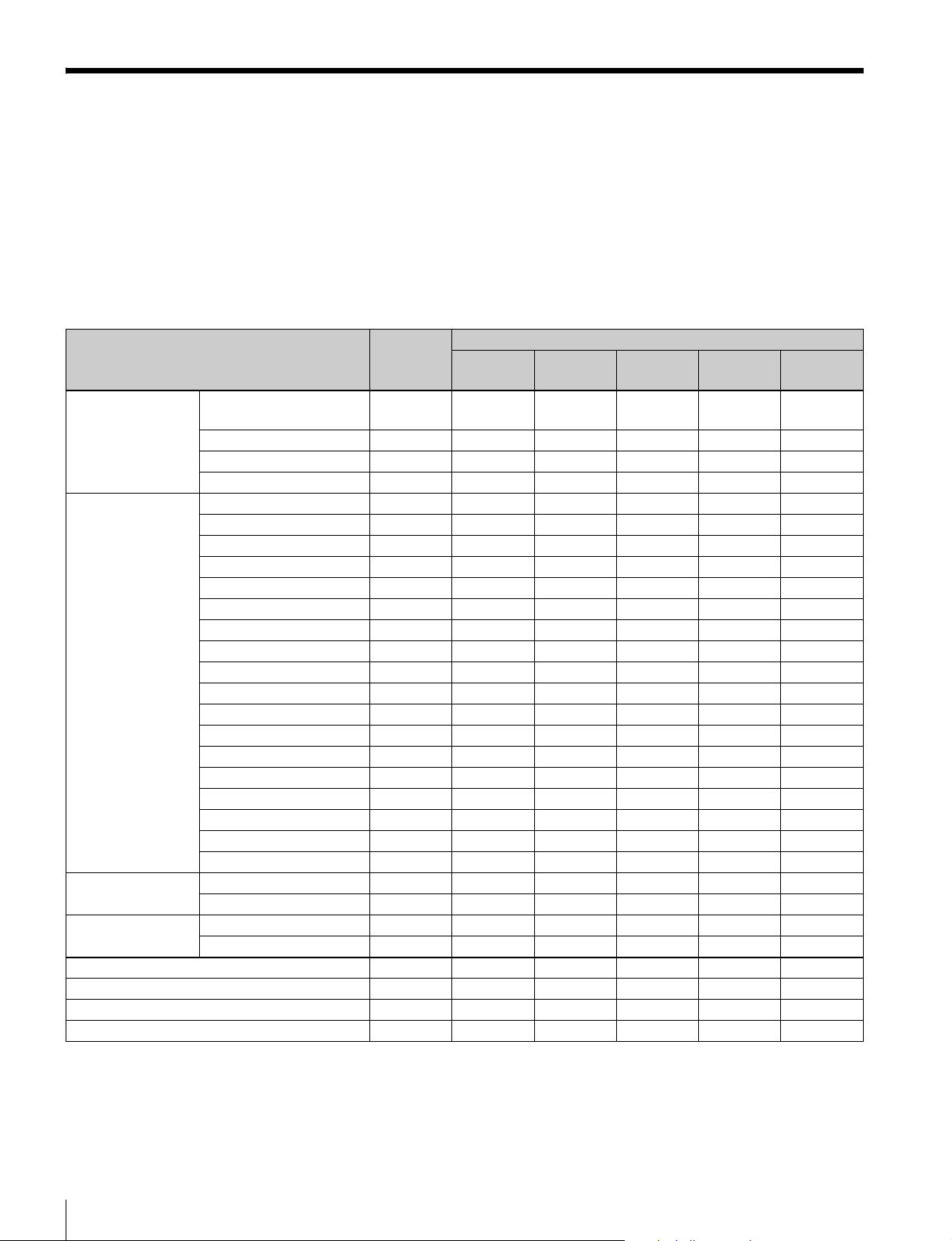
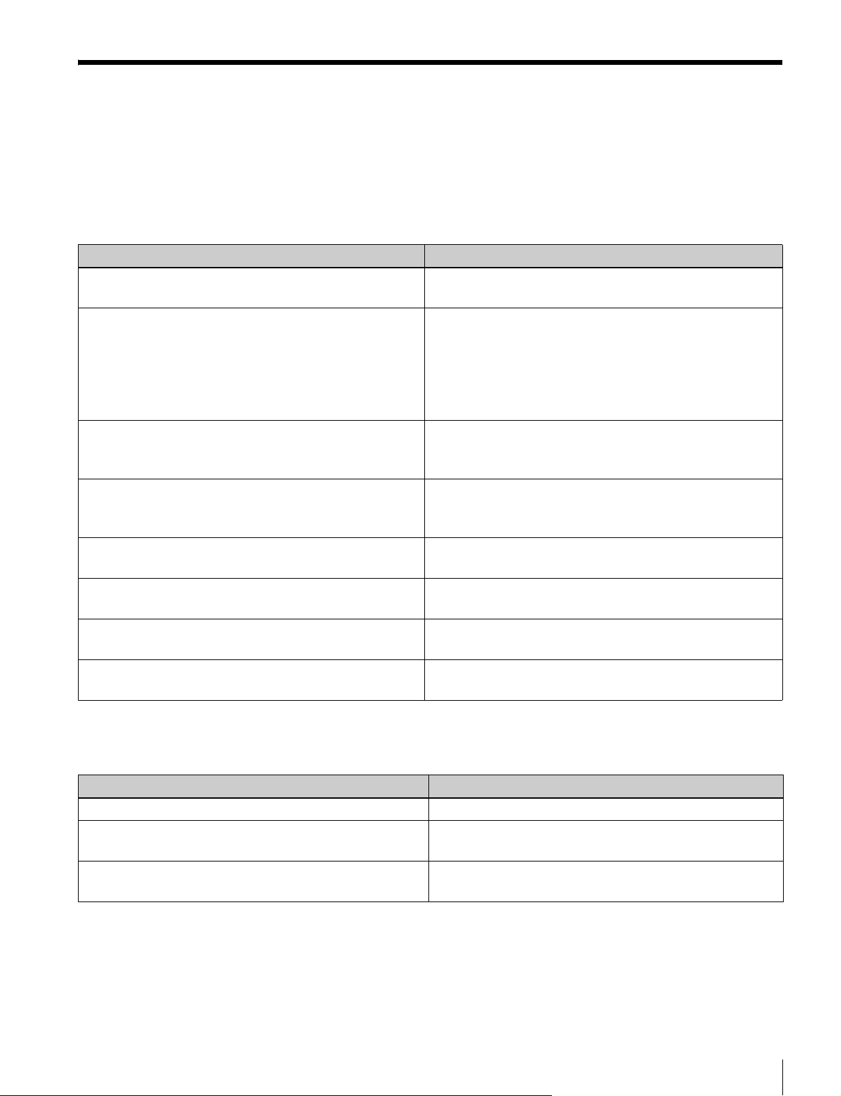
入出力端子と入力アダプター
本機には、2 系統の 3G/HD/SD-SDI 入力端子と HDMI 入力端子、DisplayPort 入力端子が標準装備されています。
本書では、これらの端子を「標準入力」と呼んでいます。
また、本機は、別売の入力アダプターを組み合わせることにより、入出力端子パネルを自由に構成できます。
各端子に入力可能な信号は次の表のとおりです。各端子に割り付ける入力信号の種類やフォーマットは、Channel
Configuration メニューで指定します。
入出力端子と入力アダプター一覧
入力信号 標準入力 入力アダプター
BKM-220D BKM-227W BKM-229X
シリアルデジタル入力 シングルリンク SD-SDI
コンポーネント 525/625
シングルリンク HD-SDI ○
デュアルリンク HD-SDI ○ (2) ○
シングルリンク 3G-SDI ○ ○
アナログ入力 コンポジット NTSC
コンポジット PAL
コンポジット PAL-M
コンポジットSECAM
Y/CNTSC
Y/CPAL
Y/CPAL-M
Y/CSECAM
YPbPr525i/625i
RGB525i/625i
YPbPr/RGB1080/24PsF
YPbPr/RGB1080/24P
YPbPr/RGB1080/50i(25PsF)
YPbPr/RGB1080/25P
YPbPr/RGB1080/60i(30PsF)
YPbPr/RGB1080/30P
YPbPr/RGB720/50P
YPbPr/RGB720/60P
HDMI ビデオ
コンピューター
DisplayPort ビデオ
コンピューター
シリアルデジタル入力端子数 2 2 − − 2 2
アナログ入力端子数 − − 1 1 − −
HDMI 入力端子数 1 − − − − −
DisplayPort 入力端子数 1 − − − − −
○○ ○○
○
○
○
○
○
○
○
○
○
○
○
○
○
○
○
○
○
○
○
○
○
○
BKM-243HS/
244CC
○○
BKM250TG
○:入力可能
○(2):アダプター 2 枚使用
◆ 詳細は、オペレーションマニュアルの「対応信号フォーマット」をご覧ください。
入出力端子と入力アダプター
16
Page 17
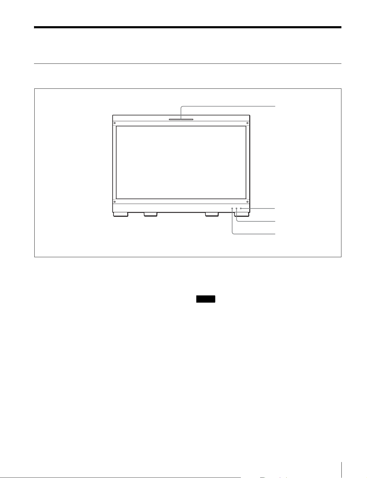
各部の名称と働き(BVM-F250)
前面パネル
1 タリーランプ
2 OPERATE ランプ
a タリーランプ
出荷時の設定では、PARALLELREMOTE 端子(側面)の
8 番ピンと 9 番ピンをショートさせると点灯します。
SystemConfiguration メニューの ParallelRemote メニュー
の設定により、PARALLELREMOTE 端子の別のピンをタ
リー用に使うこともできます。
b OPERATE(操作)ランプ
MAINPOWER スイッチ(左側面)をオンにすると、出画
に必要な内部データの初期化が始まり、OPERATE ランプ
がしばらく赤く点滅します。出画後は、初期化が完了する
まで緑に点滅します。初期化が終わり、モニターが動作状
態になると緑に点灯します。
また、モニターがスタンバイ状態のときは、OPERATEラ
ンプが赤く点灯します。
モニターがスタンバイ状態になるのは以下の場合です。
• SystemConfiguration メニューの Power メニューで、
StandbyMode を On に設定していて、MAINPOWER ス
イッチ(左側面)をオンにしたとき(初期化のためしば
らく点滅してから点灯します。)
• 外部操作により、モニターを動作状態からスタンバイ状
態に切り換えたとき
3 OVERRANGE ランプ
4 ECO ランプ
モニターがスタンバイ状態のとき、コントローラーの
MONITORI/1 スイッチを押してモニターを動作状態にす
ると緑に点灯します。
ご注意
• OPERATE ランプが赤く点滅している間は、モニターを
動作状態にすることはできません。ランプが点灯するま
でお待ちください。
• OPERATE ランプが緑に点滅している間は、モニターが
完全な動作状態になっていないため、画像が正確に表示
できません。ランプが緑に点灯するまでお待ちください。
◆ OPERATE ランプによってエラーや警告を表示することがあり
ます。詳細については、「ランプによるエラー/警告表示」(18
ページ)をご覧ください。
c OVERRANGE(オーバーレンジ)ランプ
ABL(AutomaticBrightnessLimiter)が動作するとアン
バー色に点灯します。また、信号処理回路のダイナミックレ
ンジを超えた場合、アンバー色に点灯します。
OVERRANGE ランプ点灯時は、コントラストまたはブラ
イトネスを下げてご使用ください。
各部の名称と働き(BVM-F250)
17
Page 18

◆ OVERRANGE ランプによってエラーや警告を表示することが
あります。詳細については、「ランプによるエラー/警告表示」
(18 ページ)をご覧ください。
d ECO(エコ)ランプ
本機の消費電力の状態に応じて点灯色が変化します。消費
電力が大きくなるにつれ、緑、黄、マゼンタの順で点灯し
ます。黄またはマゼンタ表示になった場合にはコントラス
ト / ブライトネス調整設定などによって表示輝度を下げる
ことをお勧めします。
スクリーンセーバーが働く約 1 分前から速い点滅となりま
す。
スクリーンセーバー動作後は、緑でゆっくりの点滅になり
ます。
◆ ECO ランプによってエラーや警告を表示することがあります。
詳細については、「ランプによるエラー/警告表示」(18 ペー
ジ)をご覧ください。
ランプによるエラー/警告表示
本機が動作中、前面パネルの OPERATE ランプと OVER
RANGE ランプ、ECO ランプにより、エラーや警告が表示
されることがあります。
エラー表示や警告表示が出た場合は、ソニーの営業担当者
またはサービス担当者にお問い合わせください。
エラー表示
ECO
ランプ
黄点灯
黄点灯
黄点滅
マゼンタ点灯アンバー
マゼンタ点滅アンバー
OVER
RANGE
ランプ
アンバー
点灯
アンバー
点滅
アンバー
点灯
点滅
点灯
OPERATE
ランプ
赤点滅 パネル電源異常
赤点滅 パネル温度異常
赤点滅 外気温センサー異常
赤点滅 FAN 異常
赤点滅 デバイス異常
症状
警告表示
ECO
ランプ
OVER
RANGE
ランプ
アンバー
−
点滅
アンバー
−
点灯
OPERATE
ランプ
−
−
症状
パネル温度上昇からパネルを
保護するため輝度を下げている
オーバーレンジ
−:エラー表示以外の状態
各部の名称と働き(BVM-F250)
18
Page 19
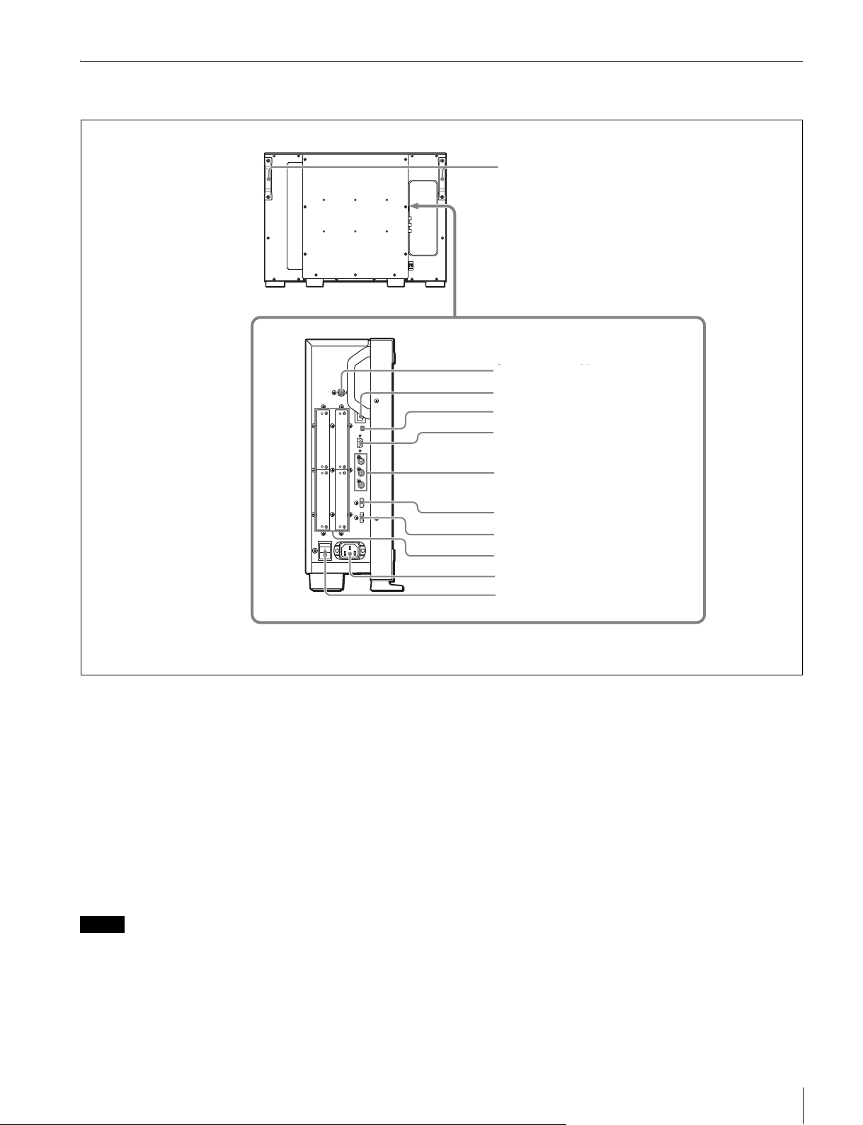
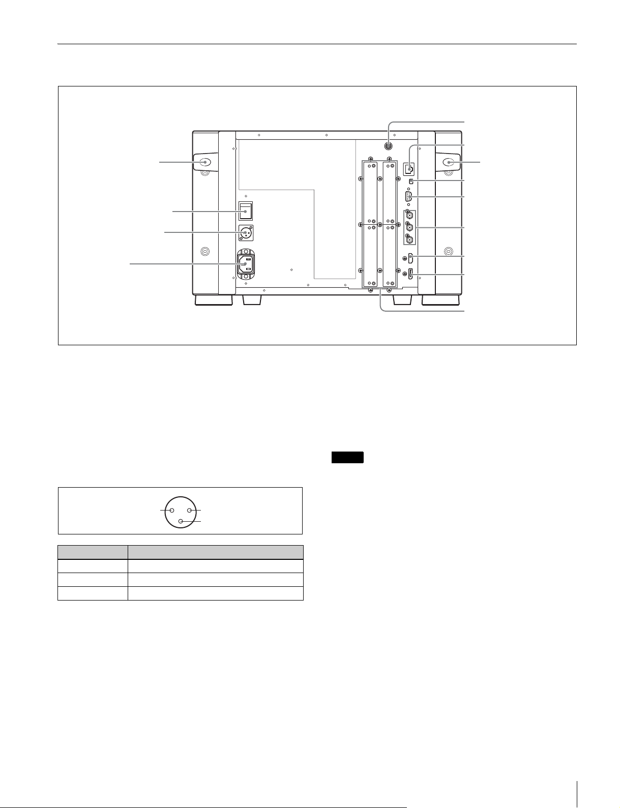
後面/左側面パネル
ハンドル
1 DC5VOUT 端子
1 DC5VOUT 端子
2 LAN(10/100) 端子
3 NETWORK スイッチ
4 PARALLELREMOTE 端子
5 STANDARDPORT(標準ポート)
a DC5VOUT 端子(凹)
コントローラー用の DC 電源です。
SMF-700 または BKM-37H/38H に付属のケーブルで、コン
トローラーの DC5V/12VIN 端子と接続します。
b LAN(10/100) 端子(10BASE-T/100BASE-TX)
SMF-700 または BKM-37H/38H に付属のケーブルで、コン
トローラーの LAN(10/100)端子に接続します。または、
10BASE-T/100BASE-TX の LAN ケーブル(シールドタイ
プ、別売)で、ネットワークまたはコントローラーの LAN
(10/100) 端子に接続します。
6 HDMI 入力端子
7 DisplayPort 入力端子
8 入力オプションポート
9 ACIN 端子
0 MAINPOWER スイッチ
• LAN ケーブルご使用の際は、輻射ノイズによる誤動作を
防ぐため、シールドタイプのケーブルを使用してくださ
い。
• ネットワークの使用環境により、接続速度に差が生じる
ことがあります。
c NETWORK スイッチ
LAN:ネットワークに接続する。
PEERTOPEER:コントローラーの LAN(10/100) 端子と
直接 1 対 1 で接続する。
ご注意
• 安全のために、周辺機器を接続する際は、過大電圧を持
つ可能性があるコネクターをこの端子に接続しないでく
ださい。
接続については本書の指示に従ってください。
各部の名称と働き(BVM-F250)
19
Page 20

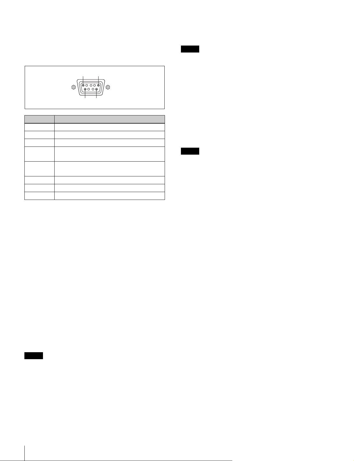
d PARALLELREMOTE(パラレルリモート)端子(D-
sub9 ピン、凹)
パラレルコントロールスイッチを構成してモニターを外部
操作します。ピン配置と出荷時の各ピンへの機能の割り付
けは以下のとおりです。
15
96
ピン番号 機能
1 入力信号チャンネル 1 を指定(数値ボタンの機能)
2 入力信号チャンネル 2 を指定(数値ボタンの機能)
3 同期信号の選択(SYNC ボタンの機能)
4 画面を白黒表示にするか、入力信号に応じて自動切り
換えにするかを選択(MONO ボタンの機能)
5 MarkerSetting メニューで設定したマーカーを一括し
て ON/OFF(MARKER ボタンの機能)
6、7 未設定
8 タリーランプの ON/OFF
9GND
各ピンへの機能の割り付けは、SystemConfiguration メ
ニューの ParallelRemote メニューで変更できます。
像が表示できます。デジタル画像信号の暗号化記述を使用
した著作権保護技術である HDCP にも対応しています。
ご注意
• 本機は HDMI の音声信号には対応していません。
• HDMI ケーブル(別売)は、HDMI ロゴを取得した
Category2(HighSpeedHDMICable) をご使用ください。
g DisplayPort 入力端子
DisplayPort 信号を入力します。
DisplayPort は VESAによって策定されたデジタル機器間
で映像/音声信号をデジタルのまま 1 本のケーブルで送る
ことができるインターフェースです。
デジタル画像信号の暗号化記述を使用した著作権保護技術
である HDCPにも対応しています。
ご注意
本機は DisplayPortの音声信号には対応していません。
h 入力オプションポート
別売の入力アダプターを取り付けます。
◆ 入力アダプターの取り付けについては、26 ページをご覧くださ
い。
◆ 入力可能な信号については、「入出力端子と入力アダプター」
(16 ページ)をご覧ください。
以下のようにピンの設定を変えて、各機能の On/Off や有効
/無効を切り換えます。
On または有効:各ピンと 9 ピンをショートさせる。
Off または無効:各ピンをオープンにする。
e STANDARDPORT(標準ポート)
SDIINPUT1(SDI 入力 1)端子
シリアルデジタル信号を入力します(標準 SDI 入力 1)。
SDIINPUT2(SDI 入力 2)端子
シリアルデジタル信号を入力します(標準 SDI 入力 2)。
MONITOROUT(モニター出力)端子
SDIINPUT1 または SDIINPUT2 端子の MONITOROUT
出力です。
ご注意
MONITOROUT 出力は、本線系出力としての規格を満足
していません。
f HDMI 入力端子
HDMI 信号を入力します。
HDMI(High-DefinitionMultimediaInterface) とは、デジタ
ル機器間で映像/音声信号をデジタルのまま 1 本のケーブ
ルで送ることができるインターフェースです。高品質な映
i ACIN(AC 電源入力)端子(3 ピン)
付属の AC 電源コードで AC 電源を接続します。
j MAINPOWER(主電源)スイッチ
? 側に押すとモニターは動作状態になります。
SystemConfiguration メニューの Power メニューの設定に
より、このスイッチを入れたときに、モニターをスタンバ
イ状態にすることもできます。
各部の名称と働き(BVM-F250)
20
Page 21
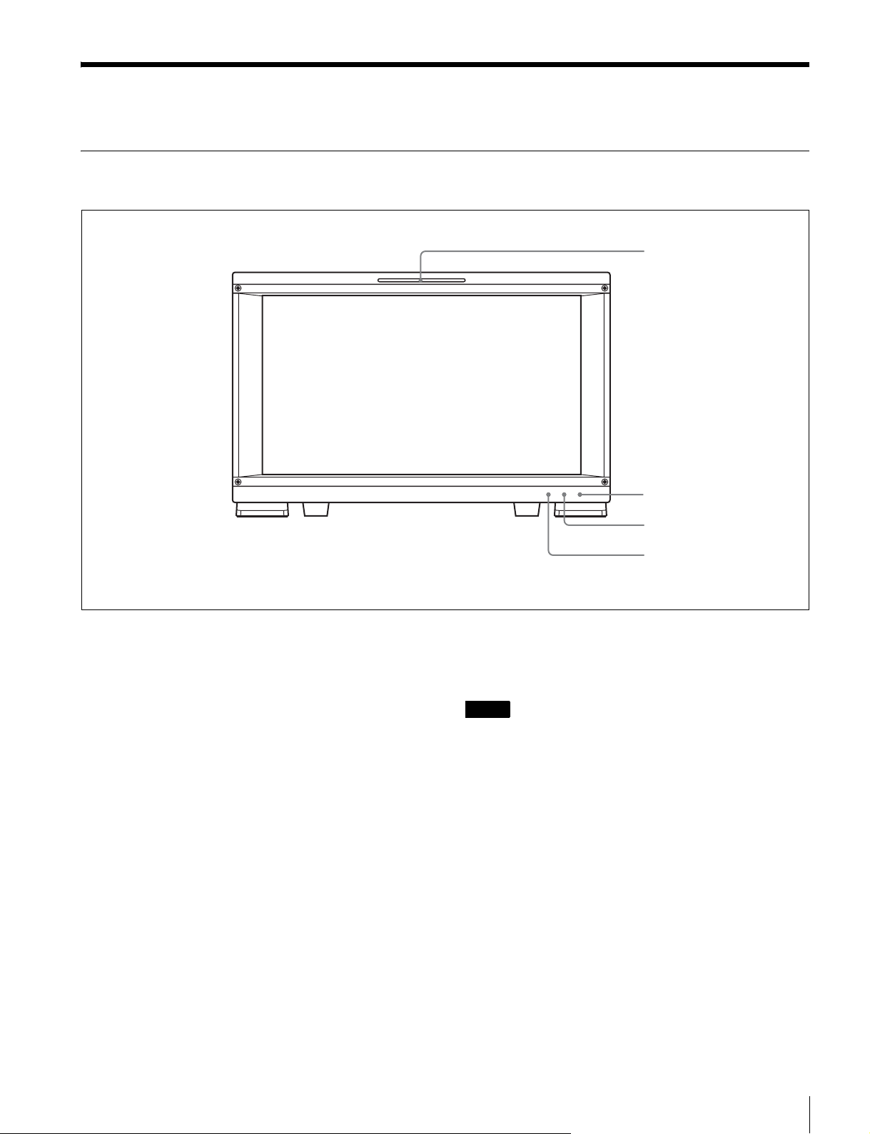
各部の名称と働き(BVM-F170)
前面パネル
1 タリーランプ
2 OPERATE ランプ
a タリーランプ
出荷時の設定では、PARALLELREMOTE 端子(後面)の
8 番ピンと 9 番ピンをショートさせると点灯します。
SystemConfiguration メニューの ParallelRemote メニュー
の設定により、PARALLELREMOTE 端子の別のピンをタ
リー用に使うこともできます。
b OPERATE(操作)ランプ
MAINPOWER スイッチ(後面)をオンにすると、出画に
必要な内部データの初期化が始まり、OPERATE ランプが
しばらく赤く点滅します。出画後は、初期化が完了するま
で緑に点滅します。初期化が終わり、モニターが動作状態
になると緑に点灯します。
また、モニターがスタンバイ状態のときは、OPERATE ラ
ンプが赤く点灯します。
モニターがスタンバイ状態になるのは以下の場合です。
• SystemConfiguration メニューの Power メニューで、
StandbyMode を On に設定していて、MAINPOWER ス
イッチ(後面)をオンにしたとき(初期化のためしばら
く点滅してから点灯します。)
• 外部操作により、モニターを動作状態からスタンバイ状
態に切り換えたとき
3 OVERRANGE ランプ
4 ECO ランプ
モニターがスタンバイ状態のとき、コントローラーの
MONITORI/1 スイッチを押してモニターを動作状態にす
ると緑に点灯します。
ご注意
• OPERATE ランプが赤く点滅している間は、モニターを
動作状態にすることはできません。ランプが点灯するま
でお待ちください。
• OPERATEランプが緑に点滅している間は、モニターが
完全な動作状態になっていないため、画像が正確に表示
できません。ランプが緑に点灯するまでお待ちください。
◆ OPERATE ランプによってエラーや警告を表示することがあり
ます。詳細については、「ランプによるエラー/警告表示」(22
ページ)をご覧ください。
c OVERRANGE(オーバーレンジ)ランプ
ABL(AutomaticBrightnessLimiter)が動作するとアン
バー色に点灯します。また、信号処理回路のダイナミックレ
ンジを超えた場合、アンバー色に点灯します。
OVERRANGE ランプ点灯時は、コントラストまたはブラ
イトネスを下げてご使用ください。
各部の名称と働き(BVM-F170)
21
Page 22
◆ OVERRANGE ランプによってエラーや警告を表示することが
あります。詳細については、「ランプによるエラー/警告表示」
(22 ページ)をご覧ください。
d ECO(エコ)ランプ
本機の消費電力の状態に応じて点灯色が変化します。消費
電力が大きくなるにつれ、緑、黄、マゼンタの順で点灯し
ます。黄またはマゼンタ表示になった場合にはコントラス
ト / ブライトネス調整設定などによって表示輝度を下げる
ことをお勧めします。
スクリーンセーバーが働く約 1 分前から速い点滅となりま
す。
スクリーンセーバー動作後は、緑でゆっくりの点滅になり
ます。
◆ECOランプによってエラーや警告を表示することがあります。
詳細については、「ランプによるエラー/警告表示」(22 ペー
ジ)をご覧ください。
ランプによるエラー/警告表示
本機が動作中、前面パネルの OPERATE ランプと OVER
RANGE ランプ、ECO ランプにより、エラーや警告が表示
されることがあります。
エラー表示や警告表示が出た場合は、ソニーの営業担当者
またはサービス担当者にお問い合わせください。
エラー表示
ECO
ランプ
黄点灯
黄点灯
黄点滅
マゼンタ点灯アンバー
マゼンタ点滅アンバー
OVER
RANGE
ランプ
アンバー
点灯
アンバー
点滅
アンバー
点灯
点滅
点灯
OPERATE
ランプ
赤点滅 パネル電源異常
赤点滅 パネル温度異常
赤点滅 外気温センサー異常
赤点滅 FAN 異常
赤点滅 デバイス異常
症状
警告表示
ECO
ランプ
OVER
RANGE
ランプ
アンバー
−
点滅
アンバー
−
点灯
OPERATE
ランプ
−
−
症状
パネル温度上昇からパネルを
保護するため輝度を下げている
オーバーレンジ
−:エラー表示以外の状態
各部の名称と働き(BVM-F170)
22
Page 23
後面パネル
4 DC5VOUT 端子
5 LAN(10/100) 端子
ハンドル
1 MAINPOWER スイッチ
2 DCIN24V-28V 端子
3 ACIN 端子
a MAINPOWER(主電源)スイッチ
オンにするとモニターは動作状態になります。
SystemConfiguration メニューの Power メニューの設定に
より、このスイッチを入れたときに、モニターをスタンバ
イ状態にすることもできます。
b DCIN24V-28V(DC 電源入力 ) 端子(XLR3 ピン、
凸)
24V 〜 28V の DC 電源を接続します。
21
3
ピン番号 機能
1 −(GND)
2 +(DC24V-28V)
3NC
c ACIN(AC 電源入力)端子(3 ピン)
付属の AC 電源コードで AC 電源を接続します。
d DC5VOUT 端子(凹)
コントローラー用の DC 電源です。
SMF-700 または BKM-39H に付属のケーブルで、コント
ローラーの DC5V/12VIN 端子と接続します。
ハンドル
6 NETWORK スイッチ
7 PARALLELREMOTE
端子
8 STANDARDPORT
(標準ポート)
8 HDMIIN 端子
9 HDMIIN 入力端子
q; DisplayPort 入力端子
qa 入力オプションポート
e LAN(10/100) 端子(10BASE-T/100BASE-TX)
SMF-700 または BKM-39H に付属のケーブルで、コント
ローラーの LAN(10/100)端子に接続します。または、
10BASE-T/100BASE-TX の LAN ケーブル(シールドタイ
プ、別売)で、ネットワークまたはコントローラーの LAN
(10/100) 端子に接続します。
ご注意
• 安全のために、周辺機器を接続する際は、過大電圧を持
つ可能性があるコネクターをこの端子に接続しないでく
ださい。
接続については本書の指示に従ってください。
• LAN ケーブルご使用の際は、輻射ノイズによる誤動作を
防ぐため、シールドタイプのケーブルを使用してくださ
い。
• ネットワークの使用環境により、接続速度に差が生じる
ことがあります。
f NETWORK スイッチ
LAN:ネットワークに接続する。
PEERTOPEER:コントローラーの LAN(10/100) 端子と
直接 1 対 1 で接続する。
各部の名称と働き(BVM-F170)
23
Page 24
g PARALLELREMOTE(パラレルリモート)端子(D-
sub9 ピン、凹)
パラレルコントロールスイッチを構成してモニターを外部
操作します。ピン配置と出荷時の各ピンへの機能の割り付
けは以下のとおりです。
15
96
ピン番号 機能
1 入力信号チャンネル 1 を指定(数値ボタンの機能)
2 入力信号チャンネル 2 を指定(数値ボタンの機能)
3 同期信号の選択(SYNC ボタンの機能)
4 画面を白黒表示にするか、入力信号に応じて自動切り
換えにするかを選択(MONO ボタンの機能)
5 MarkerSetting メニューで設定したマーカーを一括し
て ON/OFF(MARKER ボタンの機能)
6、7 未設定
8 タリーランプの ON/OFF
9GND
各ピンへの機能の割り付けは、SystemConfiguration メ
ニューの ParallelRemote メニューで変更できます。
像が表示できます。デジタル画像信号の暗号化記述を使用
した著作権保護技術である HDCP にも対応しています。
ご注意
• 本機は HDMI の音声信号には対応していません。
• HDMI ケーブル(別売)は、HDMI ロゴを取得した
Category2(HighSpeedHDMICable) をご使用ください。
j DisplayPort 入力端子
DisplayPort 信号を入力します。
DisplayPort は VESAによって策定されたデジタル機器間
で映像/音声信号をデジタルのまま 1 本のケーブルで送る
ことができるインターフェースです。
デジタル画像信号の暗号化記述を使用した著作権保護技術
である HDCPにも対応しています。
ご注意
本機は DisplayPortの音声信号には対応していません。
k 入力オプションポート
別売の入力アダプターを取り付けます。
◆ 入力アダプターの取り付けについては、27 ページをご覧くださ
い。
◆ 入力可能な信号については、「入出力端子と入力アダプター」
(16 ページ)をご覧ください。
以下のようにピンの設定を変えて、各機能の On/Off や有効
/無効を切り換えます。
On または有効:各ピンと 9 ピンをショートさせる。
Off または無効:各ピンをオープンにする。
h STANDARDPORT(標準ポート)
SDIINPUT1(SDI 入力 1)端子
シリアルデジタル信号を入力します(標準 SDI 入力 1)。
SDIINPUT2(SDI 入力 2)端子
シリアルデジタル信号を入力します(標準 SDI 入力 2)。
MONITOROUT(モニター出力)端子
SDIINPUT1 または SDIINPUT2 端子の MONITOROUT
出力です。
ご注意
MONITOROUT 出力は、本線系出力としての規格を満足
していません。
i HDMIIN(HDMI 入力)端子
HDMI 信号を入力します。
HDMI(High-DefinitionMultimediaInterface) とは、デジタ
ル機器間で映像/音声信号をデジタルのまま 1 本のケーブ
ルで送ることができるインターフェースです。高品質な映
各部の名称と働き(BVM-F170)
24
Page 25

設置環境
入力アダプターについて
照明環境
モニターの色再現は、モニターそのものの性能だけではな
く、周囲の環境光(照明)に大きく影響を受けます。
このため周囲光を調整し、黒が浮かない環境下で使用する
ことをおすすめします。
視野角
オペレーターから画面全体を見る場合の角度は画面中心か
ら上下左右 0°± 5°以内が理想です。± 15°以上ずれない
ようにしてください。
入力アダプターは、モニターの任意の入力オプションポー
トに装着できます。
ご注意
本機に以下の入力アダプターを装着する際は、指定したシ
リアル番号の製品を使用してください。
• BKM-220D:シリアル番号 2100001 以降
指定した入力アダプターを装着しないと、本機は電磁波
妨害規格の要求を満足できません。
• BKM-227W:シリアル番号 2100001以降
指定した入力アダプターを装着しないと、正しく動作し
ない場合や性能を満足しない場合があります。
• BKM-229X:シリアル番号 2200001 以降
指定した入力アダプターを装着しないと、正しく動作し
ない場合や性能を満足しない場合があります。
• BKM-243HS:シリアル番号 2108355 以降
指定した入力アダプターを装着しないと、本機は電磁波
妨害規格の要求を満足できません。また、正しく動作し
ない場合や性能を満足しない場合があります。
• BKM-250TG:シリアル番号 7300001 以降
5 種類すべての 3D 信号アナライズ機能を動作させるに
は、シリアル番号 7300001 以降の製品を使用してくださ
い。
入力アダプターを組み込んだり、取り出すときは、必ずモ
ニターの MAINPOWER スイッチを切り、電源コードを抜
いてください。感電の原因になることがあります。
設置環境/入力アダプターについて
25
Page 26
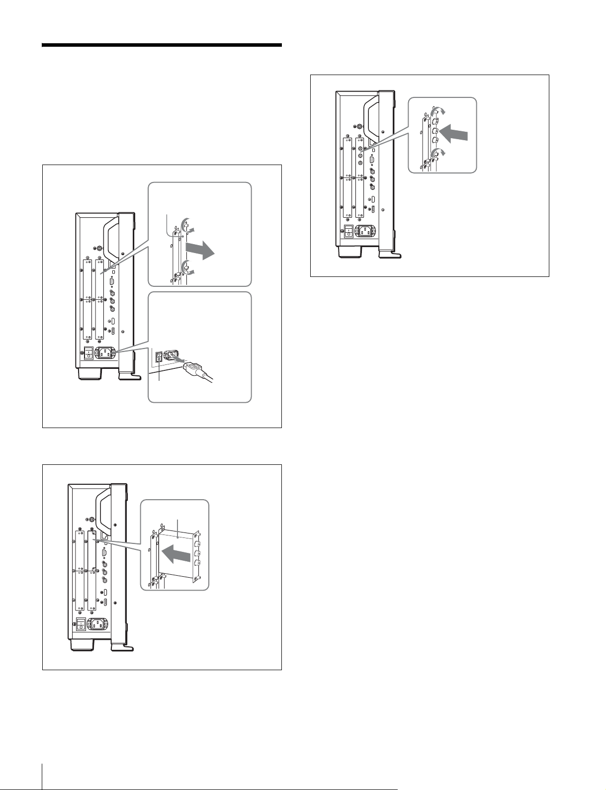
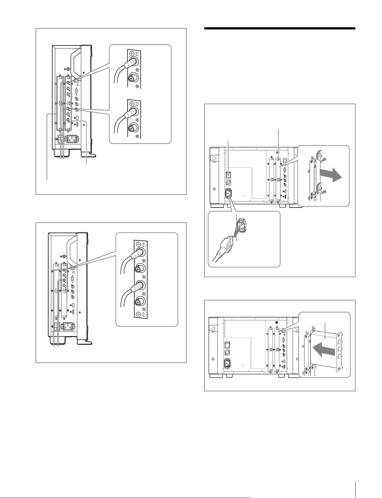
入力アダプターの取り付け
(BVM-F250)
1
ネジ 2 本を緩め、モニター側面の入力オプションポート
のカバーをはずす。
入力オプション
ポートのカバー
3
入力アダプターがモニター内部の端子にはまるまで押
し込み、ネジ 2 本を締めて固定する。
MAINPOWER スイッチ
がオフになっていること
を確認し、電源コードを
抜く。
オフ
2
基板面を手前にして、入力アダプターを挿入する。
基板面
デュアルリンク HD-SDI 信号を接続する場
合は
入力アダプター BKM-243HS または BKM-244CC が2枚、
または BKM-250TG が 1 枚必要です。
BKM-243HS または BKM-244CC を使用するときは入力アダ
プターを OPTION1 と 2 または OPTION3 と 4 のオプショ
ンポートに装着してください。
BKM-243HS または BKM-244CC と BKM-250TG を組み合
わせて使用することはできません。
ケーブルを接続するときは
BKM-243HS または BKM-244CC を使用時、リンク A
信号を OPTION1 または OPTION3 に入力し、リンク B 信
号を OPTION2 または OPTION4 に入力します。接続する
ときは、OPTION1 と 2 または OPTION3 と 4 のオプショ
ンポートに装着されたアダプターの同じ入力番号の端子
(INPUT1 同士または INPUT2 同士)に、ケーブルを接続
してください。
入力アダプターの取り付け(BVM-F250)
26
Page 27
デュアルリンクのケーブル接続例
入力アダプターの取り付け
INPUT1
INPUT2
INPUT1
INPUT2
OPTION1 と 2
OPTION3 と 4
BKM-250TG を使用時、リンク A 信号を INPUT1 に、リ
ンク B 信号を INPUT2 に入力します。
(BVM-F170)
1
ネジ 2 本を緩め、モニター後面の入力オプションポート
のカバーをはずす。
MAINPOWER スイッチ
がオフになっていること
を確認し、電源コードを
抜く。
入力オプション
ポートのカバー
INPUT1
INPUT2
3D 信号アナライズ機能を使用する場合は
3D に対応した BKM-250TG(シリアル番号 7300001 以降)
を使用し、左用の信号を INPUT1 に、右用の信号を
INPUT2 に入力します。
2
基板面を手前にして、入力アダプターを挿入する。
基板面
入力アダプターの取り付け(BVM-F170)
27
Page 28
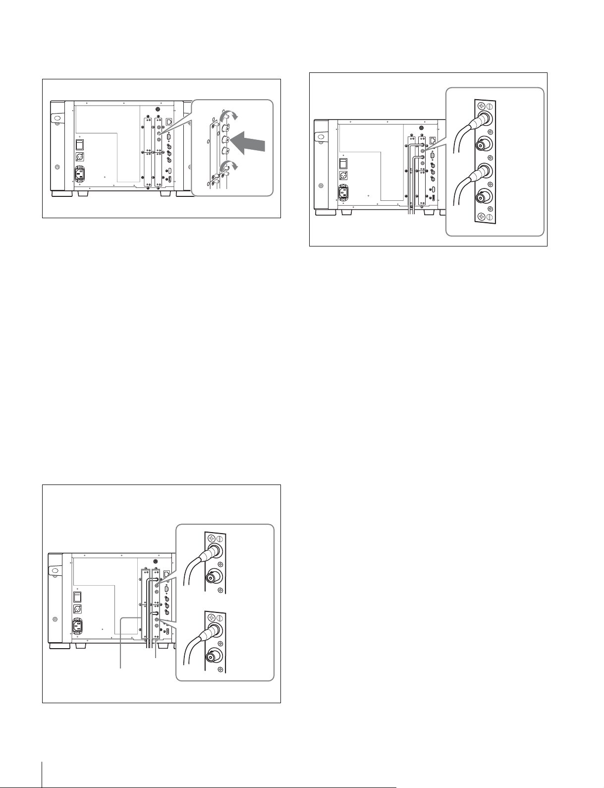
3
入力アダプターがモニター内部の端子にはまるまで押
し込み、ネジ 2 本を締めて固定する。
デュアルリンク HD-SDI 信号を接続する場
合は
入力アダプター BKM-243HS または BKM-244CC が2枚、
または BKM-250TG が 1 枚必要です。
BKM-243HS または BKM-244CC を使用するときは入力アダ
プターを OPTION1 と 2 または OPTION3 と 4 のオプショ
ンポートに装着してください。
BKM-243HS または BKM-244CC と BKM-250TG を組み合
わせて使用することはできません。
BKM-250TG を使用時、リンク A 信号を INPUT1 に、リ
ンク B 信号を INPUT2 に入力します。
INPUT1
INPUT2
3D 信号アナライズ機能を使用する場合は
3D に対応した BKM-250TG(シリアル番号 7300001 以降)
を使用し、左用の信号を INPUT1 に、右用の信号を
INPUT2 に入力します。
ケーブルを接続するときは
BKM-243HS または BKM-244CC を使用時、リンク A
信号を OPTION1 または OPTION3 に入力し、リンク B 信
号を OPTION2 または OPTION4 に入力します。接続する
ときは、OPTION1 と 2 または OPTION3 と 4 のオプショ
ンポートに装着されたアダプターの同じ入力番号の端子
(INPUT1 同士または INPUT2 同士)に、ケーブルを接続
してください。
デュアルリンクのケーブル接続例
INPUT1
INPUT2
INPUT1
INPUT2
OPTION
3と4
OPTION
1と2
入力アダプターの取り付け(BVM-F170)
28
Page 29
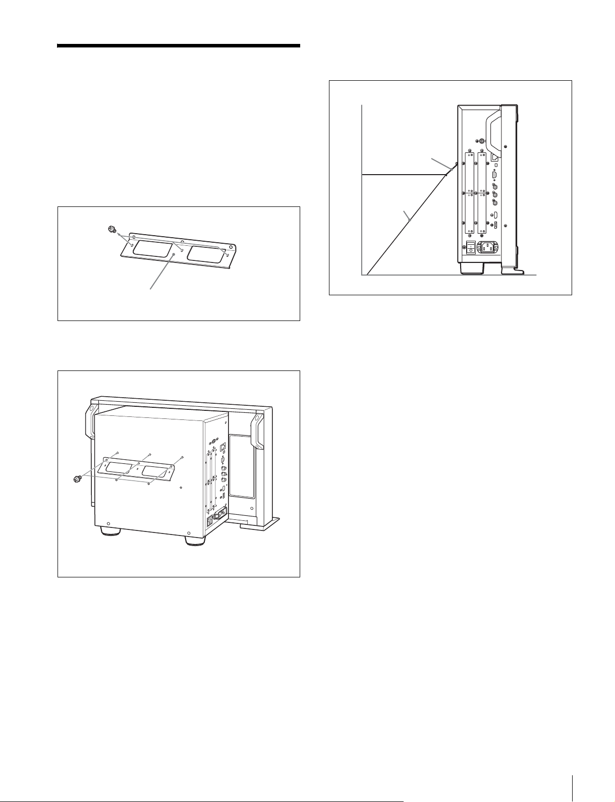
転倒防止ブラケットの取り
付け(BVM-F250)
3
転倒防止ブラケットにひもなどを掛けて、床面や壁面
などに固定する。
付属のブラケットを使うことにより、モニターの転倒を防
ぐことができます。
1
転倒防止ブラケットに取り付けてあるネジ 3 本をはず
す。
転倒防止ブラケット(付属)
2
はずしたネジ 3 本で転倒防止ブラケットをモニター後面
に取り付ける。
転倒防止
ブラケット
ひも
転倒防止ブラケットの取り付け(BVM-F250)
29
Page 30
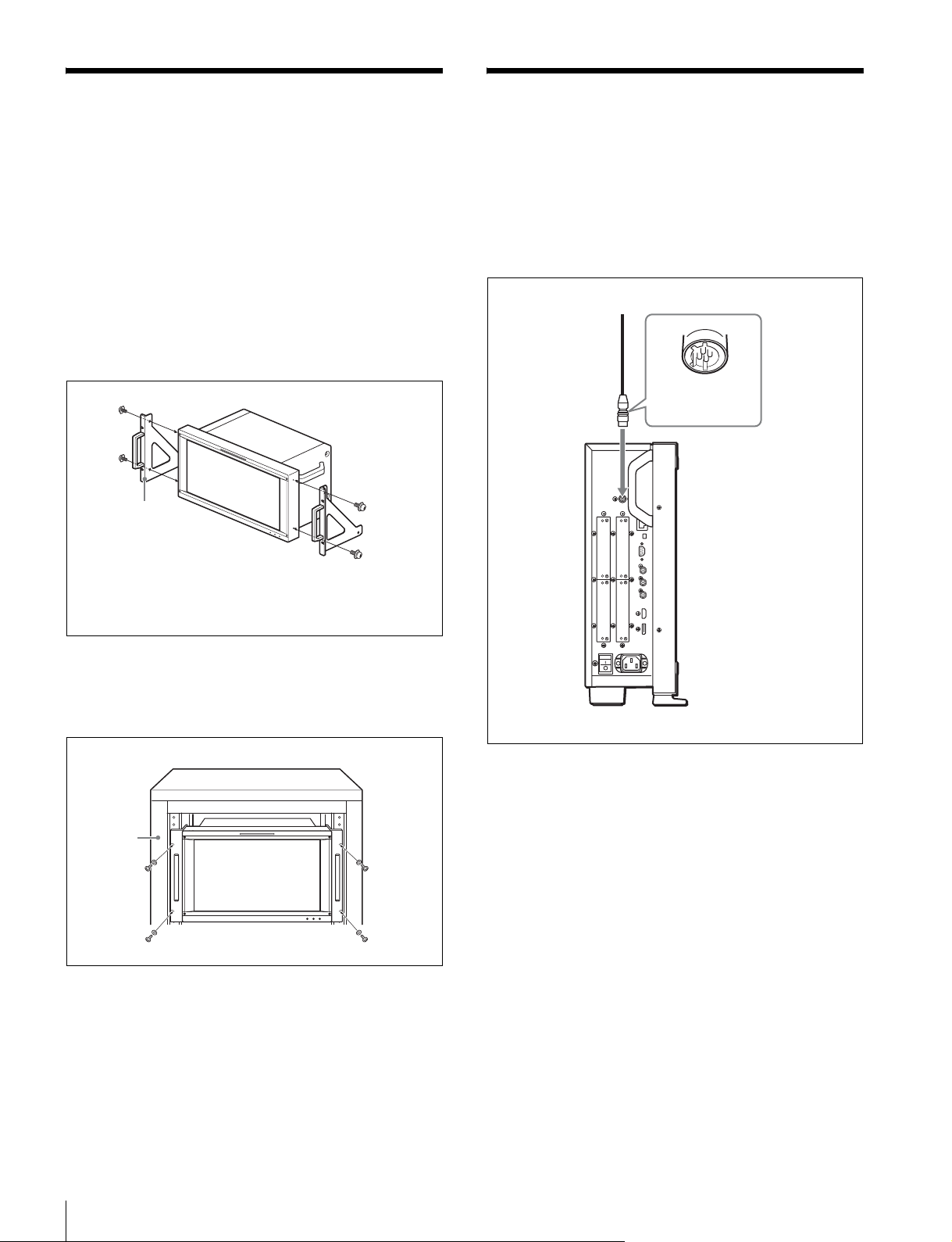
ラックへの取り付け
(BVM-F170)
本機を EIA 標準 19 インチラックに取り付けるには、付属
のラックマウントブラケットとラックマウント取り付けネ
ジを使用します。
1
本機底面の足(4 個)を取りはずす。
2
ラックマウントブラケット取り付けネジで、本機の両
側面にラックマウントブラケットを取り付ける。
ラックマウント
ブラケット
接続(BVM-F250)
DC5VOUT 端子にケーブルをつなぐときのご注意
ケーブル両端の凸凹を確認し、必ず凸側をモニターに接続
してください。
つなぐときは、ケーブル先端の形と DC5VOUT 端子の形
を合わせるようにして、差し込んでください。
凸コネクター
を差し込む。
ラックマウント
ブラケット取り
付けネジ
3
ラックマウントブラケットをラックにネジ止めして、
本機をラックに取り付ける。
ラックのネジに合った市販のネジをお使いください。
ラック
ラックへの取り付け(BVM-F170)/接続(BVM-F250)
30
Page 31

コントローラー(BKM-16R)を接続
する
BVM-F250
DC5V
OUT 端子
LAN を使って複数台を接続する
コントローラーは最大 32 台のモニターを制御することがで
きます。モニター 1 台につき 4 台のコントローラーがシン
グル接続できます。
ご注意
NETWORK スイッチ
tPEERTOPEER に
LAN(10/100) 端子
SMF-700 など
コントローラー
(BKM-16R)
1
モニターの MAINPOWER スイッチをオフにする。
DC5V/12V
IN 端子
NETWORK スイッチ
tPEERTOPEER に
LAN
(10/100) 端子
コントローラーはサブネットを越えてモニターをコント
ロールすることはできません。
NETWORK スイッチ
tLAN に
BVM-F250
LAN
(10/100) 端子
スイッチングハブ
(AUTOMDI/
MDI-X 機能付きを
推奨)
BVM-F250
LAN
(10/100)
端子
2
モニターとコントローラーの NETWORK スイッチを
PEERTOPEER に設定する。
3
モニターの LAN(10/100) 端子とコントローラーの LAN
(10/100)端子を SMF-700 または BKM-37H/38H に付
属のケーブル、または 10BASE-T/100BASE-TX のスト
レート仕様の LAN ケーブル(シールドタイプ、別売)
で接続する。
ご注意
別売の LAN ケーブルを接続する際は、ノイズによる誤
動作を防ぐため、必ずシールドタイプのケーブルを使
用してください。
4
コントローラーの DC5V/12VIN 端子とモニターの DC
5VOUT 端子を SMF-700 または BKM-37H/38H に付属
のケーブルで接続する。
または、コントローラーの DC5V/12VIN 端子にコン
トローラーに付属の AC アダプターの出力ケーブルを
接続する。
AC アダプター
(BKM-16R に付属)
コントローラー
(BKM-16R)
DC5V/12VIN
端子
NETWORK スイッチ
tLAN に
LAN
(10/100)
端子
接続(BVM-F250)
31
Page 32

1
モニターの MAINPOWER スイッチをオフにする。
2
10BASE-T/100BASE-TX の LAN ケーブル(シールドタ
イプ、別売)でネットワークに接続する。
ご注意
• 別売の LAN ケーブルを接続する際は、ノイズによる誤
動作を防ぐため、必ずシールドタイプのケーブルを使
用してください。
• 別売のスイッチングハブは、ストレート/クロスケー
ブルの自動選択機能(AUTOMDI/MDI-X)をもった
機器をおすすめします。
3
コントローラーの DC5V/12VIN端子にコントローラー
に付属の AC アダプターの出力ケーブルを接続する。
ご注意
複数台を接続するには LAN 設定が必要です。
NETWORK スイッチを LAN にする前に、LAN 設定を
行ってください。
◆ LAN 設定のしかたは、オペレーションマニュアルの「複数
台接続するための LAN 設定をする」をご覧ください。
接続(BVM-F170)
DC5VOUT 端子にケーブルをつなぐときのご注意
ケーブル両端の凸凹を確認し、必ず凸側をモニターに接続
してください。
つなぐときは、ケーブル先端の形と DC5VOUT 端子の形
を合わせるようにして、差し込んでください。
凸コネクター
を差し込む。
4
モニターとコントローラーの NETWORK スイッチを
LAN に設定する。
接続(BVM-F170)
32
Page 33

コントローラー(BKM-16R)を接続
する
NETWORK スイッチ
BVM-F170
tPEERTOPEER に
LAN を使って複数台を接続する
コントローラーは最大 32 台のモニターを制御することがで
きます。モニター 1 台につき 4 台のコントローラーがシン
グル接続できます。
ご注意
コントローラーはサブネットを越えてモニターをコント
ロールすることはできません。
NETWORK スイッチ
tLAN に
LAN(10/100) 端子
SMF-700 など
コントローラー
(BKM-16R)
1
モニターの MAINPOWER スイッチをオフにする。
2
モニターとコントローラーの NETWORK スイッチを
PEERTOPEER に設定する。
DC5V/12V
IN 端子
NETWORK スイッチ
tPEERTOPEER に
LAN
(10/100) 端子
DC5V
OUT 端子
BVM-F170
LAN
(10/100) 端子
AC アダプター
(BKM-16R に付属)
BVM-F170
LAN
(10/100)
端子
スイッチングハブ
(AUTOMDI/
MDI-X 機能付きを
推奨)
3
モニターの LAN(10/100) 端子とコントローラーの LAN
(10/100)端子を SMF-700 または BKM-39H に付属の
ケーブル、または 10BASE-T/100BASE-TX のストレー
ト仕様の LAN ケーブル(シールドタイプ、別売)で接
続する。
ご注意
別売の LAN ケーブルを接続する際は、ノイズによる誤
動作を防ぐため、必ずシールドタイプのケーブルを使
用してください。
4
コントローラーの DC5V/12VIN 端子とモニターの DC
5VOUT 端子を SMF-700 または BKM-39H に付属の
ケーブルで接続する。
または、コントローラーの DC5V/12VIN 端子にコン
トローラーに付属の AC アダプターの出力ケーブルを
接続する。
コントローラー
(BKM-16R)
DC5V/12VIN
端子
LAN
(10/100)
端子
NETWORK スイッチ
tLAN に
接続(BVM-F170)
33
Page 34

1
モニターの MAINPOWER スイッチをオフにする。
2
10BASE-T/100BASE-TX の LAN ケーブル(シールドタ
イプ、別売)でネットワークに接続する。
ご注意
• 別売の LAN ケーブルを接続する際は、ノイズによる誤
動作を防ぐため、必ずシールドタイプのケーブルを使
用してください。
• 別売のスイッチングハブは、ストレート/クロスケー
ブルの自動選択機能(AUTOMDI/MDI-X)をもった
機器をおすすめします。
3
コントローラーの DC5V/12VIN端子にコントローラー
に付属の AC アダプターの出力ケーブルを接続する。
ご注意
複数台を接続するには LAN 設定が必要です。
NETWORK スイッチを LAN にする前に、LAN 設定を
行ってください。
◆ LAN 設定のしかたは、オペレーションマニュアルの「複数
台接続するための LAN 設定をする」をご覧ください。
電源の投入
(BVM-F250)
電源コードを接続する
1
AC 電源コードを左側面の ACIN 端子に差し込み、AC
プラグホルダーを AC 電源コードに取り付ける。
AC 電源コード(付属)
AC プラグホルダー(付属)
4
モニターとコントローラーの NETWORK スイッチを
LAN に設定する。
AC プラグホルダーをはめて、プラグが抜けないように固定
する。
2
固定レバーがロックするまで、AC プラグホルダーをは
めこむ。
電源コードをはずすには
AC プラグホルダーの固定レバーを両側からはさんでロック
をはずし、引き抜きます。
ご注意
このモニターには、必ず付属の電源コードをご使用くださ
い。他の電源コードを使用する場合には、このモニターは
VCCI の規格に適合しない可能性があります。
電源の投入(BVM-F250)
34
Page 35

モニターの電源を入れる
電源の投入
左側面の MAINPOWER スイッチをオンにして電源を入れ
ます。
はじめてお使いになるときは、SelectArea 画面が表示され
ますので、使用地域を選択してください。
◆ 使用地域の設定は、36 ページをご覧ください。
電源を入れてから、約 30 分以上のウォームアップ時間が必
要です。
モニターがスタンバイ状態のとき
スタンバイ状態のときは OPERATE ランプが赤く点灯しま
すので、コントローラーの MONITORI/1 スイッチを押し
てオンにしてください。
OPERATE ランプが緑に点灯し、モニターが動作状態にな
ります。
(BVM-F170)
電源に接続する
本機は AC 電源または DC 電源で動作します。
AC 電源コードを接続する
1
AC電源コードを後面の ACIN端子に差し込み、AC プラ
グホルダーを AC 電源コードに取り付ける。
AC 電源コード(付属)
AC プラグホルダー(付属)
AC プラグホルダーをはめて、プラグが抜けないように固定
する。
2
固定レバーがロックするまで、AC プラグホルダーをは
めこむ。
電源コードをはずすには
AC プラグホルダーの固定レバーを両側からはさんでロック
をはずし、引き抜きます。
電源の投入(BVM-F170)
35
Page 36

ご注意
このモニターには、必ず付属の電源コードをご使用くださ
い。他の電源コードを使用する場合には、このモニターは
VCCI の規格に適合しない可能性があります。
使用地域の設定
DC 電源を接続する
DC 電源を DCIN24V-28V 端子に接続します。
AC 電源と DC 電源の両方が接続されている場合は、AC 電
源が優先されます。DC 電源を使用する場合は、AC 電源
コードをはずしてください。
モニターの電源を入れる
後面の MAINPOWER スイッチをオンにして電源を入れま
す。
はじめてお使いになるときは、SelectArea 画面が表示され
ますので、使用地域を選択してください。
◆ 使用地域の設定は、36 ページをご覧ください。
電源を入れてから、約 30 分以上のウォームアップ時間が必
要です。
モニターがスタンバイ状態のとき
スタンバイ状態のときは OPERATE ランプが赤く点灯しま
すので、コントローラーの MONITORI/1 スイッチを押し
てオンにしてください。
OPERATE ランプが緑に点灯し、モニターが動作状態にな
ります。
はじめてお使いになるときはお使いになる地域の選択を
行ってください。
地域を選択すると、メニュー内の各項目がお使いの地域に
合った値に設定されます。
地域別基本設定値
3
1
5
4
3
1
NorthAmerica
2
LatinAmerica
PAL&PAL-NArea Paraguay D65 0% SMPTE/
NTSC&PAL-MArea OtherArea D65 7.5% Betacam ITU-R
3
Africa
Australasia
Europe
Middle-East
4
AsiaExcept
Japan
5
Japan
3
Color
Setup
Temp
Level
D65 7.5% Betacam ITU-R
Argentina D65 0% SMPTE/
Uruguay D65 0% SMPTE/
D65 0% SMPTE/
NTSCArea D65 7.5% Betacam ITU-R
PALArea D65 0% SMPTE/
D93 0% SMPTE/
2
Component
Level
EBU-N10
EBU-N10
EBU-N10
EBU-N10
EBU-N10
EBU-N10
Color
Profile
BT.709
ITU-R
BT.709
ITU-R
BT.709
ITU-R
BT.709
BT.709
ITU-R
BT.709
BT.709
ITU-R
BT.709
ITU-R
BT.709
36
使用地域の設定
Page 37

PAL&PAL-N または NTSC&PAL-M を選び、
ENTER(Ent) ボタンを押してください。
4AsiaExceptJapan を選んだとき:
ENTER ボタン
UP/DOWN ボタン
Ent ボタン
1
MAINPOWER スイッチをオンにして電源を入れる。
SelectArea 画面が表示されます。
1 北アメリカ
Select Area
North America B
Latin America B
Africa B
Australasia B
Europe B
Middle-East B
Asia Except Japan B
Japan B
2 ラテンアメリカ
3 アフリカ
オーストラリア/
ニュージーランド
ヨーロッパ/ロシア
中東
4 日本を除くアジア
5 日本
Select Area
NTSC 地域
Asia Except Japan
NTSC Area B
PAL Area B
PAL 地域
下の地図でグレーに色付けされた地域でお使いの場合
は NTSCArea を選び、他の地域でお使いの場合は
PALArea を選び、ENTER(Ent) ボタンを押してくだ
さい。
2
コントローラーの UP/DOWN ボタンを押して、モニ
ターをお使いになる地域を選び、ENTER(Ent) ボタン
を押す。
LatinAmerica(ラテンアメリカ)または AsiaExcept
Japan(日本以外のアジア)を選ぶと、次の画面が表示
されます。
2LatinAmerica を選んだとき:
Select Area
Latin America
PAL & PAL-N Area B
NTSC & PAL-M Area B
PAL&PAL-N 地域
NTSC&PAL-M 地域
3
各設定値を確認する。
Select Area
XXXXXXXXXX
Color Temp: xx
Setup Level: xx
Component Level: xx
Color Profile:
Cancel
Confirm
xx
Cancel:変更、設定された設定値を変更前の値に戻
し、地域選択の画面に戻るとき選択する。
Confirm:変更、設定された設定値を保存、反映し、
使用地域の選択を終了するとき選択する。
使用地域の設定
37
Page 38

設定値については「地域別基本設定値」(36 ページ)をご
覧ください。
設定値を保存、反映した後でもメニュー操作によって以下
の設定を変更することができます。
• ColorTemp(色温度)
• SetupLevel(セットアップレベル)(NTSCSetupLevel、
BetacamSetupLevel)
• ComponentLevel(コンポーネントレベル)
• ColorProfile(カラープロファイル)
◆ 設定変更について詳しくは、オペレーションマニュアルをご覧
ください。
38
使用地域の設定
Page 39

メニューリスト
各メニューの詳細はオペレーションマニュアルをご覧ください。
Adjustment メニュー
メインメニュー 第 1 階層 第 2 階層 第 3 階層 第 4 階層
Adjustment Picture Adj Auto Auto Adjust
Color Bar
Restore Factory Data
Status
Input Port
Format
Matrix
Manual Adjust
Copy From Preset Value
Other Monitor Monitor ID
Memory Stick
Color Temp Adj Manual Manual Adjust
Original Value
Signal
Contrast/Bright Hold
Auto Auto Adjust
Target Color Temp
x
y
Target Luminance
Contrast/Bright Hold
1)
Copy From Preset Value
Other Monitor Monitor ID
Memory Stick
Restore Factory Data
Position Adj H Shift
V Shift
1)この項目は BVM-F170 のみに搭載されています。
メニューリスト
39
Page 40

ChannelConfiguration メニュー
メインメニュー 第 1 階層 第 2 階層 第 3 階層 第 4 階層
Channel Configuration Format 3G/HD/SD-SDI
Dual Link HD-SDI
Composite
YC
Component
HDMI
Input Port DisplayPort
Input No
Screen Aspect SD
Sync Mode HDMI Auto
Color Temp
Picture Preset
Matrix HD
SD
HDMI/DisplayPort Auto
Color Profile Color Profile
Marker Preset Color Space
H Shift Offset Gamma
Channel Name
NTSC Setup Level
Component Level
Betacam Setup Level
RGB Range HD
HDMI
DisplayPort
HDMI/DisplayPort Auto
1080I/PsF 24PsF
25PsF/50I
30PsF/60I
Copy From Other CH
Other Monitor Monitor ID
Memory Stick
AuxiliarySetting メニュー
第1階層 第2階層 第3階層 第4階層メインメニュー
Auxiliary Setting Native Scan Mode
Aperture Value
NTSC Comb Filter
Filter Switch
Peak White Control
40
メニューリスト
Page 41

FunctionSetting メニュー
メインメニュー 第 1 階層 第 2 階層 第 3 階層 第 4 階層
Function Setting Marker Setting Aspect Marker Aspect Marker
Aspect Mode
Aspect
Line
Thickness
Color
Bright
Blanking
Area Marker 1 Area Marker 1
Aspect Mode
Aspect
Area Size
Width
Height
Mode
Thickness
Color
Bright
Area Marker 2 Area Marker 2
Aspect Mode
Aspect
Area Size
Width
Height
Mode
Thickness
Color
Bright
Center Marker Center Marker
Mode
Color
Bright
H Position
V Position
Copy From Preset Value
Other Monitor Monitor ID
Memory Stick
P&P Setting Side by Side Line Display
Line Color
Pixel Zoom Setting Line Color Line Bright
3D Setting Horopter Check Left
Right
Capture Load
Rename
Internal Signal Delete
Function Switch Scan Mode
Native Scan
16:9
H Delay
V Delay
External Sync
Comb
Aperture
Mono
Blue Only
R Off
G Off
B Off
Chroma Up
Interlace
Marker
Aspect Marker
Area Marker 1
Area Marker 2
Center Marker
Aspect Marker-Line
Aspect Blanking-Half
Aspect Blanking-Black
Side by Side
Audio Level Meter
ALM Hold Reset
Time Code
Difference
Checkerboard
L/R Switch
Horopter Check
Flip H
メニューリスト
41
Page 42

SystemConfiguration メニュー
メインメニュー 第 1 階層 第 2 階層 第 3 階層 第 4 階層
System Configuration Network Monitor ID
Group ID
Network Setting IP Address
Subnet Mask
Default Gateway
Address
Protocol Setting SDCP/SDAP Community
SDCP Port No
SDAP Port No
SDAP Broadcast
SDAP Broadcast Period
Acceptable IP Address
Reset Protocol Setting
Parallel Remote Parallel Remote
1 Pin - 8 Pin
Power Standby Mode
Power On Status
Default CH
On Screen Set Input Information Format
Position
CH No
Position
CH Name
Position
Scan Mode
Position
Closed Caption Closed Caption
Type
Service 708
Service 608
OSD Level
Audio Level Meter Audio CH
Position
Transparency
Peak Hold
Time Code VITC/LTC
Position
Level
Over Range
Password Change Password
Apply Password Adjustment
Channel Configuration
Auxiliary Setting
Function Setting
System Configuration
Individual Item Network
Parallel Remote
File Management Power
Controller On Screen Set
Key Protect Date/Time
Scan Mode Skip
Screen Saver
Date/Time
Scan Mode Skip
Screen Saver
Monitor Upgrade Software Upgrade
Kernel Upgrade
FPGA Upgrade
DisplayPort Upgrade
Maintenance
42
メニューリスト
Page 43

FileManagement メニュー
メインメニュー 第 1 階層 第 2 階層 第 3 階層 第 4 階層
File Management Save To Memory Stick
Copy From Other Monitor Monitor ID
Memory Stick
Delete Memory Stick
Data Maintenance Back Up System Data
Restore System Data
SystemStatus メニュー
メインメニュー 第 1 階層 第 2 階層 第 3 階層 第 4 階層
System Status CH Status
Serial No
SDI Payload ID Status Payload ID
Video Standard
Sampling Structure
Bit Depth
Picture Rate
Scanning Method
Link Number
Current Status
Format
I/PsF/P
HDMI/DP Status Pixel Encoding
Color Depth
Matrix
RGB Range
Model Name
Serial No
Software Version
Operation Time
Panel On Time
Network Switch
Controller Status Model Name
Serial No
Software Version
Network Switch
Port Status Option1-Option4
Model Name
メニューリスト
43
Page 44

Controller メニュー/ KeyProtect メニュー
メインメニュー 第 1 階層 第 2 階層 第 3 階層 第 4 階層
Controller Network Network Setting IP Address
Subnet Mask
Default Gateway
Address
SNMP Setting Contact
Name
Location
Trap Mode
Trap Address Setting
Trap Address Status
Reset Mode/Address
Authentication
Community
Protocol Setting SDCP/SDAP Community
SDCP Port No
SDAP Port No
SDAP Broadcast
SDAP Broadcast Period
Reset Protocol Setting
Function Key F1 - F16
Monitor ID Display
Controller Upgrade Software Upgrade
Kernel Upgrade
Key Protect
44
メニューリスト
Page 45

仕様(BVM-F250)
画像系
パネル 有機 EL パネル
画像サイズ 24.5 型
表示エリア(H × V)
543.4 × 305.6mm
解像度(H × V)
1920 × 1080ピクセル(FullHD)
アスペクト比 16:9
有効画素数 99.99%
パネルドライバー
RGB10-bit
パネル表示フレームレート
48Hz、50Hz、60Hz、72Hz、75Hz
オペレーションマニュアルの「画像・
フレーム表示」を参照してください。
1) 48Hz、60Hz、72Hz は、フレームレート
1/1.001 にも対応します。
視野角 ( パネルの仕様 )
89°/89°/89°/89°
(上/下/左/右、コントラスト >10:1)
ノーマルスキャン
0%スキャン
ネイティブスキャン
信号のピクセルをパネルのピクセルに 1:1
でマッピング表示、または非スクエア
ピクセルの SD信号(信号システムの
Hピクセル数が 720または 1440)また
は HDMI/DisplayPortビデオの 640×
480の SD信号を、V方向は 2倍、H方
向は画面アスペクト比が正しくなるよ
うスケーリング処理し、同時にアパー
チャー係数、フィルター係数などを補
正して画質を最適化した表示
アンダースキャン
3%アンダースキャン
オーバースキャン
0%スキャンに対して 5%オーバースキャ
ン部をマスク表示
色温度 D65、D93(他の色温度にも設定可)
標準輝度 100cd/m
(100%白色信号入力時)
カラースペース
ITU-RBT.709、EBU、SMPTE-C、
2
(Preset1〜Preset5)
F250Native
2)
2) BVM-F250独自の色度点です。BVMF250 として最も広色域のカラースペース
設定です。
Xy
R 0.681 0.319
G 0.189 0.724
B 0.141 0.051
(Typical)
ウォームアップ時間
30 分
入力
SDI 入力 BNC(× 2)
入力インピーダンス:75Ω 不平衡
信号フォーマット
オペレーションマニュアルの「対応信
1)
HDMI 入力 HDMI コネクター(× 1)
DisplayPort 入力
号システム」、「対応信号フォーマッ
ト」を参照してください。
サンプリング周波数
3G-SDI:
Y/Cb/Cr(4:2:2)
148.5MHz/74.25MHz/74.25MHz
Y/Cb/Cr(4:4:4)
148.5MHz/148.5MHz/148.5MHz
G/B/R(4:4:4)
148.5MHz/148.5MHz/148.5MHz
HD-SDI:
Y/Cb/Cr(4:2:2)
74.25MHz/37.125MHz/37.125
MHz
SD-SDI:
Y/Cb/Cr(4:2:2)
13.5MHz/6.75MHz/6.75MHz
量子化
3G-SDI:10 ビット/サンプル、12 ビッ
ト/サンプル
HD-SDI:10 ビット/サンプル
SD-SDI:10 ビット/サンプル
HDCP 対応、DeepColor 対応
信号フォーマット
オペレーションマニュアルの「対応信
号フォーマット」の「HDMI/
DisplayPort」を参照してください。
DisplayPort コネクター(× 1)
HDCP 対応、18/24/30bpp(bitsper
pixel)対応
仕様(BVM-F250)
45
Page 46

信号フォーマット
オペレーションマニュアルの「対応信
号フォーマット」の「HDMI/
DisplayPort」を参照してください。
オプションポート
4 ポート
信号フォーマット
オペレーションマニュアルの「対応信
号システム」、「対応信号フォーマット」
を参照してください。
パラレルリモート
D-sub9 ピン(凹)(× 1)
シリアルリモート(LAN)
Ethernet(10BASE-T/100BASE-TX):
RJ-45(× 1)
出力
SDI 出力 BNC(× 1)(モニター出力)
出力信号振幅:800mVp-p± 10%
出力インピーダンス:75Ω 不平衡
伝送距離:
3G-SDI: 最大 70m
HD-SDI: 最大 100m
SD-SDI: 最大 200m
3)
3)
4)
ご注意
MONITOROUT 出力は、本線系出力とし
て規格を満足していません。
3) (株)フジクラ製の同軸ケーブル 5C-FB また
は同等品使用時
4) (株)フジクラ製の同軸ケーブル 5C-2V また
は同等品使用時
DC5VOUT 丸型 4 ピン(凹)(× 1)
一般
電源 AC100V-240V
1.6A-0.8A、50/60Hz
消費電力 約 145W(最大)
約 72W(平均消費電力、工場出荷時)
動作温度 0°C〜35°C
推奨使用温度:20°C〜30°C
動作湿度 0%〜90%(結露のないこと)
保存・輸送温度 −20°C〜 +60°C
保存・輸送湿度 0%〜90%
動作・保存・輸送気圧
700hPa〜1060hPa
質量 約 13.0kg
付属品 AC 電源コード(1)
3 極→ 2 極変換プラグ(1)
ACプラグホルダー(1)
転倒防止ブラケット(1)
オペレーションガイド(本書)
(1)
CD-ROM(1)
保証書(1)
別売品 モニターコントロールユニット BKM-16R
コントローラーアタッチメントスタンド
BKM-37H、BKM-38H
モニターインターフェースケーブル SMF-
700
SDI4:2:2入力アダプター BKM-220D(シ
リアル番号 2100001以降)
NTSC/PAL入力アダプター BKM-227W
(シリアル番号 2100001以降)
アナログコンポーネント入力アダプター
BKM-229X(シリアル番号 2200001以
降)
HD/D1-SDI入力アダプター BKM-243HS
(シリアル番号 2108355以降)
HD/SD-SDIクローズドキャプションアダ
プター BKM-244CC
3G/HD/SD-SDI入力アダプター BKM-
250TG(シリアル番号 7300001以降)
ご注意
入力アダプターによっては、指定したシ
リアル番号の製品を使用する必要があり
ます。本機で使用できる入力アダプター
のシリアル番号について詳しくは、「入力
アダプターについて」(25 ページ)をご
覧ください。
本機は「高調波電流規格 JISC61000-3-2 適合品」です。
本機の仕様および外観は、改良のため予告なく変更するこ
とがありますが、ご了承ください。
この装置は、クラス A 情報技術装置です。この装置を家
庭環境で使用すると電波妨害を引き起こすことがありま
す。この場合には使用者が適切な対策を講ずるよう要求
されることがあります。
VCCI-A
• 必ず事前に記録テストを行い、正常に記録されている
ことを確認してください。本機や記録メディア、外部
ストレージなどを使用中、万一これらの不具合により
記録されなかった場合の記録内容の補償については、
ご容赦ください。
• お使いになる前に、必ず動作確認を行ってください。
故障その他に伴う営業上の機会損失等は保証期間中お
よび保証期間経過後にかかわらず、補償はいたしかね
ますのでご了承ください。
仕様(BVM-F250)
46
Page 47

仕様(BVM-F170)
画像系
パネル 有機 EL パネル
画像サイズ 16.5 型
表示エリア(H × V)
365.8 × 205.7mm
解像度(H × V)
1920 × 1080ピクセル(FullHD)
アスペクト比 16:9
有効画素数 99.99%
パネルドライバー
RGB10-bit
パネル表示フレームレート
48Hz、50Hz、60Hz、72Hz、75Hz
オペレーションマニュアルの「画像・
フレーム表示」を参照してください。
1) 48Hz、60Hz、72Hz は、フレームレート
1/1.001 にも対応します。
視野角 ( パネルの仕様 )
89°/89°/89°/89°
(上/下/左/右、コントラスト >10:1)
ノーマルスキャン
0%スキャン
ネイティブスキャン
信号のピクセルをパネルのピクセルに 1:1
でマッピング表示、または非スクエア
ピクセルの SD信号(信号システムの
Hピクセル数が 720または 1440)また
は HDMI/DisplayPortビデオの 640×
480の SD信号を、V方向は 2倍、H方
向は画面アスペクト比が正しくなるよ
うスケーリング処理し、同時にアパー
チャー係数、フィルター係数などを補
正して画質を最適化した表示
アンダースキャン
3%アンダースキャン
オーバースキャン
0%スキャンに対して 5%オーバースキャ
ン部をマスク表示
色温度 D65、D93(他の色温度にも設定可)
標準輝度 100cd/m
(100%白色信号入力時)
カラースペース
ITU-RBT.709、EBU、SMPTE-C、
2
(Preset1〜Preset5)
F170Native
2)
2) BVM-F170独自の色度点です。BVMF170 として最も広色域のカラースペース
設定です。
Xy
R 0.681 0.319
G 0.189 0.724
B 0.141 0.051
(Typical)
ウォームアップ時間
30 分
入力
SDI 入力 BNC(× 2)
入力インピーダンス:75Ω 不平衡
信号フォーマット
オペレーションマニュアルの「対応信
1)
HDMI 入力 HDMI コネクター(× 1)
DisplayPort 入力
号システム」、「対応信号フォーマッ
ト」を参照してください。
サンプリング周波数
3G-SDI:
Y/Cb/Cr(4:2:2)
148.5MHz/74.25MHz/74.25MHz
Y/Cb/Cr(4:4:4)
148.5MHz/148.5MHz/148.5MHz
G/B/R(4:4:4)
148.5MHz/148.5MHz/148.5MHz
HD-SDI:
Y/Cb/Cr(4:2:2)
74.25MHz/37.125MHz/37.125
MHz
SD-SDI:
Y/Cb/Cr(4:2:2)
13.5MHz/6.75MHz/6.75MHz
量子化
3G-SDI:10 ビット/サンプル、12 ビッ
ト/サンプル
HD-SDI:10 ビット/サンプル
SD-SDI:10 ビット/サンプル
HDCP 対応、DeepColor 対応
信号フォーマット
オペレーションマニュアルの「対応信
号フォーマット」の「HDMI/
DisplayPort」を参照してください。
DisplayPort コネクター(× 1)
HDCP 対応、18/24/30bpp(bitsper
pixel)対応
仕様(BVM-F170)
47
Page 48

信号フォーマット
オペレーションマニュアルの「対応信
号フォーマット」の「HDMI/
DisplayPort」を参照してください。
オプションポート
4 ポート
信号フォーマット
オペレーションマニュアルの「対応信
号システム」、「対応信号フォーマット」
を参照してください。
パラレルリモート
D-sub9 ピン(凹)(× 1)
シリアルリモート(LAN)
Ethernet(10BASE-T/100BASE-TX):
RJ-45(× 1)
出力
SDI 出力 BNC(× 1)(モニター出力)
出力信号振幅:800mVp-p± 10%
出力インピーダンス:75Ω 不平衡
伝送距離:
3G-SDI: 最大 70m
HD-SDI: 最大 100m
SD-SDI: 最大 200m
3)
3)
4)
ご注意
MONITOROUT 出力は、本線系出力とし
て規格を満足していません。
3) (株)フジクラ製の同軸ケーブル 5C-FB また
は同等品使用時
4) (株)フジクラ製の同軸ケーブル 5C-2V また
は同等品使用時
DC5VOUT 丸型 4 ピン(凹)(× 1)
一般
電源 AC100V-240V
1.2A-0.7A、50/60Hz
DC24V-28V
4.5A-3.9A
消費電力 約 110W(AC 運用時)/約 100W(DC
運用時)(最大)
約 60W(AC 運用時)/約 60W(DC 運
用時)(平均消費電力、工場出荷時)
動作温度 0°C〜35°C
推奨使用温度:20°C〜30°C
動作湿度 0%〜90%(結露のないこと)
保存・輸送温度 −20°C〜 +60°C
保存・輸送湿度 0%〜90%
動作・保存・輸送気圧
700hPa〜1060hPa
質量 約 8.6kg
付属品 AC 電源コード(1)
3 極→ 2 極変換プラグ(1)
ACプラグホルダー(1)
ラックマウントブラケット(左右各 1)
ラックマウントブラケット取り付け用
ネジ(4)
オペレーションガイド(本書)
(1)
CD-ROM(1)
保証書(1)
別売品 モニターコントロールユニット BKM-16R
コントローラーアタッチメントスタンド
BKM-39H
モニターインターフェースケーブル SMF-
700
SDI4:2:2入力アダプター BKM-220D(シ
リアル番号 2100001以降)
NTSC/PAL入力アダプター BKM-227W
(シリアル番号 2100001以降)
アナログコンポーネント入力アダプター
BKM-229X(シリアル番号 2200001以
降)
HD/D1-SDI入力アダプター BKM-243HS
(シリアル番号 2108355以降)
HD/SD-SDIクローズドキャプションアダ
プター BKM-244CC
3G/HD/SD-SDI入力アダプター BKM-
250TG(シリアル番号 7300001以降)
ご注意
入力アダプターによっては、指定したシ
リアル番号の製品を使用する必要があり
ます。本機で使用できる入力アダプター
のシリアル番号について詳しくは、「入力
アダプターについて」(25 ページ)をご
覧ください。
本機は「高調波電流規格 JISC61000-3-2 適合品」です。
本機の仕様および外観は、改良のため予告なく変更するこ
とがありますが、ご了承ください。
この装置は、クラス A 情報技術装置です。この装置を家
庭環境で使用すると電波妨害を引き起こすことがありま
す。この場合には使用者が適切な対策を講ずるよう要求
されることがあります。
VCCI-A
仕様(BVM-F170)
48
Page 49

• 必ず事前に記録テストを行い、正常に記録されている
ことを確認してください。本機や記録メディア、外部
ストレージなどを使用中、万一これらの不具合により
記録されなかった場合の記録内容の補償については、
ご容赦ください。
• お使いになる前に、必ず動作確認を行ってください。
故障その他に伴う営業上の機会損失等は保証期間中お
よび保証期間経過後にかかわらず、補償はいたしかね
ますのでご了承ください。
外形寸法図
(BVM-F250)
前面
576
551
226
254 60
508
側面
148
単位 :mm
331
424
55
34.4
15
40
後面
334.2
200
226
1) このネジ穴を使用するときは、モニター本体に入る部分が 6 〜 8mm にな
るネジを使用してください。
外形寸法図(BVM-F250)
M4
1)
100
49
Page 50

BKM-37H を使ってコントローラーを取り
BKM-37H にチルトユニットが取り付けられているとき
付けたとき
BKM-37H からチルトユニットを取りはずしたとき
前面
269.7
59.7
側面
467.7
前面
285.7
側面
483.7
75.7
底面
30
266
489.8
30
30
4-M5
195
6-Ø8
230
底面
30
266
489.8
30
30
4-M5
195
6-Ø8
230
外形寸法図(BVM-F250)
50
Page 51

BKM-38H を使ってコントローラーを取り
付けたとき
前面
271.6
61.6
側面
576
469.6
外形寸法図
(BVM-F170)
前面
436
365.8
244 59.95
368
単位 :mm
266.4
205.7
282.4
底面
266
30
側面
17
23.3
215
14.7
40
外形寸法図(BVM-F170)
51
Page 52

後面
側面
352
131
134.6
BKM-39H を使ってコントローラーを取り
付けたとき
前面
上面
17
62.3
215
4.48.7
438
443
266.4
175 62.340
325.2
外形寸法図(BVM-F170)
52
Page 53

English
Before operating the unit, please read this manual
thoroughly and retain it for future reference.
For BVM-F250/F170
Important Safety Instructions
• Read these instructions.
• Keep these instructions.
• Heed all warnings.
• Follow all instructions.
• Do not use this apparatus near water.
• Clean only with dry cloth.
• Do not block any ventilation openings.
Install in accordance with the manufacturer's
instructions.
• Do not install near any heat sources such as radiators,
heat registers, stoves, or other apparatus (including
amplifiers) that produce heat.
• Do not defeat the safety purpose of the polarized or
grounding-type plug. A polarized plug has two blades
with one wider than the other. A grounding-type plug
has two blades and a third grounding prong. The wide
blade or the third prong are provided for your safety. If
the provided plug does not fit into your outlet, consult an
electrician for replacement of the obsolete outlet.
• Protect the power cord from being walked on or pinched
particularly at plugs, convenience receptacles, and the
point where they exit from the apparatus.
• Only use attachments/accessories specified by the
manufacturer.
• Use only with the cart, stand, tripod, bracket, or table
specified by the manufacturer, or sold with the
apparatus. When a cart is used, use caution when
moving the cart/apparatus combination to avoid injury
from tip-over.
WARNING
To reduce the risk of fire or electric shock, do not
expose this apparatus to rain or moisture.
To avoid electrical shock, do not open the
cabinet. Refer servicing to qualified personnel
only.
THIS APPARATUS MUST BE EARTHED.
For BVM-F250 only
This apparatus is provided with a main switch on the left
side panel.
Install this apparatus so that user can access the main
switch easily.
For BVM-F170 only
WARNING
When installing the unit, incorporate a readily accessible
disconnect device in the fixed wiring, or connect the power
plug to an easily accessible socket-outlet near the unit. If
a fault should occur during operation of the unit, operate
the disconnect device to switch the power supply off, or
disconnect the power plug.
For BVM-F250/F170
CAUTION
The apparatus shall not be exposed to dripping or
splashing. No objects filled with liquids, such as vases,
shall be placed on the apparatus.
CAUTION
The unit is not disconnected from the AC power source
(mains) as long as it is connected to the wall outlet, even if
the unit itself has been turned off.
GB
GB
• Unplug this apparatus during lightning storms or when
unused for long periods of time.
• Refer all servicing to qualified service personnel.
Servicing is required when the apparatus has been
damaged in any way, such as power-supply cord or plug
is damaged, liquid has been spilled or objects have fallen
into the apparatus, the apparatus has been exposed to
rain or moisture, does not operate normally, or has been
dropped.
This symbol is intended to alert the user to
the presence of uninsulated “dangerous
voltage” within the product’s enclosure that
may be of sufficient magnitude to constitute
a risk of electric shock to persons.
53
Page 54

This symbol is intended to alert the user to
the presence of important operating and
maintenance (servicing) instructions in the
literature accompanying the appliance.
conforms to the safety regulations of each country if
applicable.
2. Use the Power Cord (3-core mains lead) / Appliance
Connector / Plug conforming to the proper ratings
(Voltage, Ampere).
For the customers in the U.S.A.
This equipment has been tested and found to comply with
the limits for a Class A digital device, pursuant to Part 15
of the FCC Rules. These limits are designed to provide
reasonable protection against harmful interference when
the equipment is operated in a commercial environment.
This equipment generates, uses, and can radiate radio
frequency energy and, if not installed and used in
accordance with the instruction manual, may cause
harmful interference to radio communications. Operation
of this equipment in a residential area is likely to cause
harmful interference in which case the user will be
required to correct the interference at his own expense.
You are cautioned that any changes or modifications not
expressly approved in this manual could void your
authority to operate this equipment.
All interface cables used to connect peripherals must be
shielded in order to comply with the limits for a digital
device pursuant to Subpart B of Part 15 of FCC Rules.
This device complies with Part 15 of the FCC Rules.
Operation is subject to the following two conditions: (1)
this device may not cause harmful interference, and (2) this
device must accept any interference received, including
interference that may cause undesired operation.
If you have questions on the use of the above Power Cord
/ Appliance Connector / Plug, please consult a qualified
service personnel.
For the customers in Canada
This Class A digital apparatus complies with Canadian
ICES-003.
For the customers in Europe
This product with the CE marking complies with the EMC
Directive issued by the Commission of the European
Community.
Compliance with this directive implies conformity to the
following European standards:
• EN55103-1 : Electromagnetic Interference (Emission)
• EN55103-2 : Electromagnetic Susceptibility (Immunity)
This product is intended for use in the following
Electromagnetic Environment: E4 (controlled EMC
environment, ex. TV studio).
The manufacturer of this product is Sony Corporation, 17-1 Konan, Minato-ku, Tokyo, 108-0075 Japan.
The Authorized Representative for EMC and product
safety is Sony Deutschland GmbH, Hedelfinger Strasse
61, 70327 Stuttgart, Germany. For any service or
guarantee matters please refer to the addresses given in
separate service or guarantee documents.
This apparatus shall not be used in the residential area.
WARNING: THIS WARNING IS APPLICABLE FOR
USA ONLY.
If used in USA, use the UL LISTED power cord specified
below.
DO NOT USE ANY OTHER POWER CORD.
Plug Cap Parallel blade with ground pin
(NEMA 5-15P Configuration)
Cord Type SVT or SJT, three 16 or 18 AWG wires
Length Minimum 1.5 m (4 ft .11in.), Less than 2.5 m
(8 ft .3 in.)
Rating Minimum 10A, 125V
Using this unit at a voltage other than 120V may require
the use of a different line cord or attachment plug, or both.
To reduce the risk of fire or electric shock, refer servicing
to qualified service personnel.
WARNING: THIS WARNING IS APPLICABLE FOR
OTHER COUNTRIES.
1. Use the approved Power Cord (3-core mains lead) /
Appliance Connector / Plug with earthing-contacts that
For BVM-F170 only
Attention-when the product is installed in Rack:
1.
Prevention against overloading of branch circuit
When this product is installed in a rack and is supplied
power from an outlet on the rack, please make sure that the
rack does not overload the supply circuit.
2.Providing protective earth
When this product is installed in a rack and is supplied
power from an outlet on the rack, please confirm that the
outlet is provided with a suitable protective earth
connection.
3.Internal air ambient temperature of the rack
When this product is installed in a rack, please make sure
that the internal air ambient temperature of the rack is
within the specified limit of this product.
54
Page 55

4.Prevention against achieving hazardous
condition due to uneven mechanical loading
When this product is installed in a rack, please make sure
that the rack does not achieve hazardous condition due to
uneven mechanical loading.
5.Install the equipment while taking the operating
temperature of the equipment into consideration
For the operating temperature of the equipment, refer to
the specifications of the Operation Guide.
6.When performing the installation, keep the
following space away from walls in order to
obtain proper exhaust and radiation of heat.
Lower, Upper: 4.4 cm (1
Right, Left: 1.0 cm (
3
/4 inches) or more
13
/32 inches) or more
Installez l’appareil de sorte que l’utilisateur puisse
facilement accéder à l’interrupteur principal.
Pour le BVM-F170 uniquement
AVERTISSEMENT
Lors de l’installation de l’appareil, incorporer un dispositif
de coupure dans le câblage fixe ou brancher la fiche
d’alimentation dans une prise murale facilement
accessible proche de l’appareil. En cas de problème lors du
fonctionnement de l’appareil, enclencher le dispositif de
coupure d’alimentation ou débrancher la fiche
d’alimentation.
Pour le BVM-F250/F170
For BVM-F250/F170
For the customers in Europe, Australia and New
Zealand
WARNING
This is a Class A product. In a domestic environment, this
product may cause radio interference in which case the
user may be required to take adequate measures.
For kundene i Norge
Dette utstyret kan kobles til et IT-strømfordelingssystem.
Apparatet må tilkoples jordet stikkontakt
Suomessa asuville asiakkaille
Laite on liitettävä suojamaadoituskoskettimilla
varustettuun pistorasiaan
För kunderna i Sverige
Apparaten skall anslutas till jordat uttag
Français
Pour le BVM-F250/F170
AVERTISSEMENT
ATTENTION
Eviter d’exposer l’appareil à un égouttement ou à des
éclaboussures. Ne placer aucun objet rempli de liquide,
comme un vase, sur l’appareil.
ATTENTION
Cet appareil n’est pas déconnecté de la source
d’alimentation secteur tant qu’il est raccordé à la prise
murale, même si l’appareil lui-même a été mis hors
tension.
Pour les clients au Canada
Cet appareil numérique de la classe A est conforme à la
norme NMB-003 du Canada.
Pour les clients en Europe
Ce produit portant la marque CE est conforme à la
Directive sur la compatibilité électromagnétique (EMC)
émise par la Commission de la Communauté européenne.
La conformité à cette directive implique la conformité aux
normes européennes suivantes:
• EN55103-1: Interférences électromagnétiques
(émission)
• EN55103-2: Sensibilité électromagnétique (immunité)
Ce produit est prévu pour être utilisé dans l’environnement
électromagnétique suivant: E4 (environnement EMC
contrôlé, ex. studio de télévision).
Afin de réduire les risques d’incendie ou
d’électrocution, ne pas exposer cet appareil à la
pluie ou à l’humidité.
Afin d’écarter tout risque d’électrocution, garder
le coffret fermé. Ne confier l’entretien de
l’appareil qu’à un personnel qualifié.
CET APPAREIL DOIT ÊTRE RELIÉ À LA TERRE.
Pour le BVM-F250 uniquement
Cet appareil est doté d’un interrupteur principal sur son
panneau gauche.
Le fabricant de ce produit est Sony Corporation, 1-7-1
Konan, Minato-ku, Tokyo, 108-0075 Japon.
Le représentant autorisé pour EMC et la sécurité des
produits est Sony Deutschland GmbH, Hedelfinger Strasse
61, 70327 Stuttgart, Allemagne. Pour toute question
concernant le service ou la garantie, veuillez consulter les
adresses indiquées dans les documents de service ou de
garantie séparés.
Ne pas utiliser cet appareil dans une zone résidentielle.
55
Page 56

AVERTISSEMENT
1. Utilisez un cordon d’alimentation (câble secteur à 3
fils)/fiche femelle/fiche mâle avec des contacts de mise
à la terre conformes à la réglementation de sécurité
locale applicable.
2. Utilisez un cordon d’alimentation (câble secteur à 3
fils)/fiche femelle/fiche mâle avec des caractéristiques
nominales (tension, ampérage) appropriées.
Pour toute question sur l’utilisation du cordon
d’alimentation/fiche femelle/fiche mâle ci-dessus,
consultez un technicien du service après-vente qualifié.
Pour les clients en Europe, Australie et NouvelleZélande
AVERTISSEMENT
Il s’agit d’un produit de Classe A. Dans un environnement
domestique, cet appareil peut provoquer des interférences
radio, dans ce cas l’utilisateur peut être amené à prendre
des mesures appropriées.
Beim BVM-F250/F170
VORSICHT
Das Gerät ist nicht tropf- und spritzwassergeschützt. Es
dürfen keine mit Flüssigkeiten gefüllten Gegenstände, z.
B. Vasen, darauf abgestellt werden.
VORSICHT
Solange das Netzkabel an eine Netzsteckdose
angeschlossen ist, bleibt das Gerät auch im
ausgeschalteten Zustand mit dem Strommetz verbunden.
Für Kunden in Europa
Dieses Produkt besitzt die CE-Kennzeichnung und erfüllt
die EMV-Richtlinie der EG-Kommission.
Angewandte Normen:
• EN55103-1: Elektromagnetische Verträglichkeit
(Störaussendung)
• EN55103-2: Elektromagnetische Verträglichkeit
(Störfestigkeit)
Für die folgende elektromagnetische Umgebung: E4
(kontrollierter EMV-Bereich, z.B. Fernsehstudio).
Deutsch
Beim BVM-F250/F170
WARNUNG
Um die Gefahr von Bränden oder elektrischen
Schlägen zu verringern, darf dieses Gerät nicht
Regen oder Feuchtigkeit ausgesetzt werden.
Um einen elektrischen Schlag zu vermeiden, darf
das Gehäuse nicht geöffnet werden. Überlassen
Sie Wartungsarbeiten stets nur qualifiziertem
Fachpersonal.
DIESES GERÄT MUSS GEERDET WERDEN.
Nur beim BVM-F250
Dieses Gerät ist auf der linken Seite mit einem
Hauptschalter versehen.
Installieren Sie das Gerät so, dass der Benutzer leicht auf
den Hauptschalter zugreifen kann.
Nur beim BVM-F170
WARNUNG
Beim Einbau des Geräts ist daher im Festkabel ein leicht
zugänglicher Unterbrecher einzufügen, oder der
Netzstecker muss mit einer in der Nähe des Geräts
befindlichen, leicht zugänglichen Wandsteckdose
verbunden werden. Wenn während des Betriebs eine
Funktionsstörung auftritt, ist der Unterbrecher zu betätigen
bzw. der Netzstecker abzuziehen, damit die
Stromversorgung zum Gerät unterbrochen wird.
Der Hersteller dieses Produkts ist Sony Corporation, 1-7-1
Konan, Minato-ku, Tokyo, 108-0075 Japan.
Der autorisierte Repräsentant für EMV und
Produktsicherheit ist Sony Deutschland GmbH,
Hedelfinger Strasse 61, 70327 Stuttgart, Deutschland. Bei
jeglichen Angelegenheiten in Bezug auf Kundendienst
oder Garantie wenden Sie sich bitte an die in den separaten
Kundendienst- oder Garantiedokumenten aufgeführten
Anschriften.
Dieser Apparat darf nicht im Wohnbereich verwendet
werden.
WARNUNG
1. Verwenden Sie ein geprüftes Netzkabel (3-adriges
Stromkabel)/einen geprüften Geräteanschluss/einen
geprüften Stecker mit Schutzkontakten entsprechend
den Sicherheitsvorschriften, die im betreffenden Land
gelten.
2. Verwenden Sie ein Netzkabel (3-adriges Stromkabel)/
einen Geräteanschluss/einen Stecker mit den geeigneten
Anschlusswerten (Volt, Ampere).
Wenn Sie Fragen zur Verwendung von Netzkabel/
Geräteanschluss/Stecker haben, wenden Sie sich bitte an
qualifiziertes Kundendienstpersonal.
Für Kunden in Europa, Australien und
Neuseeland
WARNUNG
Dies ist eine Einrichtung, welche die Funk-Entstörung
nach Klasse A besitzt. Diese Einrichtung kann im
Wohnbereich Funkstörungen verursachen; in diesem Fall
kann vom Betreiber verlangt werden, angemessene
Maßnahmen durchzuführen und dafür aufzukommen.
56
Page 57

Table of Contents
Using the CD-ROM Manual .............................58
Preparations........................................................58
Reading the CD-ROM Manual ..........................58
Precautions ......................................................58
On Safety ...........................................................58
On Installation....................................................58
Handling the Screen...........................................59
On Burn-in .........................................................59
On a Long Period of Use ...................................59
Handling and Maintenance of the Screen ..........59
On Dew Condensation .......................................60
On Repacking.....................................................60
Disposal of the Unit ...........................................60
On Fan Error ......................................................60
Functions Supported in Software Version 1.1
and 1.2................................................. 61
Features............................................................62
Options ............................................................. 64
Input/Output Connectors and Input
Adaptors .............................................66
Location and Function of Parts
(BVM-F250) .........................................67
Front Panel .........................................................67
Rear Panel/Left Side Panel ................................69
Location and Function of Parts
(BVM-F170) .........................................71
Front Panel .........................................................71
Rear Panel ..........................................................73
Environments of the Installation Location....75
Input Adaptors .................................................75
Installing an Input Adaptor (BVM-F250).........76
Installing an Input Adaptor (BVM-F170).........77
Attaching the Bracket (BVM-F250).................79
Mounting the Unit in a Rack (BVM-F170).......79
Connections (BVM-F250) ................................80
Connecting the Controller (BKM-16R) ............. 80
Connecting the Multiple Units with the LAN....81
Connections (BVM-F170) ................................82
Connecting the Controller (BKM-16R) ............. 82
Connecting the Multiple Units with the LAN....83
Turning on the Power (BVM-F250) .................84
Connecting the AC Power Cord ........................84
Turning on the Monitor......................................84
Turning on the Power (BVM-F170) .................85
Connecting to Power..........................................85
Turning on the Monitor......................................85
Selecting the Area............................................86
Menu Structure.................................................88
Specifications (BVM-F250)..............................94
Specifications (BVM-F170)..............................96
Dimensions (BVM-F250)..................................99
Dimensions (BVM-F170) ............................... 101
Using This Manual
This Operation Guide includes explanations for the
BVM-F250 and BVM-F170.
The model name is specified where there is a difference
between the two models. (Example: Location and
Function of Parts (BVM-F250))
Please note that the explanations are common to both
models where no model name is specified.
Table of Contents
57
Page 58

Using the CD-ROM
Manual
The supplied CD-ROM includes operation manuals for
this unit (English, French, German, Italian, Spanish,
Simplified Chinese, Traditional Chinese, Korean, and
Japanese versions).
Preparations
The following program must be installed on your computer
in order to read the operations manuals contained on the
CD-ROM.
• Adobe Reader Version 6.0 or higher
If Adobe Reader is not installed, you can download it from
the following URL:
http://www.adobe.com/
Adobe and Adobe Reader are trademarks of Adobe Systems Incorporated in
the United States and/or other countries.
Precautions
On Safety
• Operate the unit only with a power source as specified in
the “Specifications” section.
• A nameplate indicating operating voltage, power
consumption, etc., is located on the rear panel.
• Should any solid object or liquid fall into the cabinet,
unplug the unit and have it checked by qualified
personnel before operating it any further.
• Do not drop or place heavy objects on the power cord. If
the power cord is damaged, turn off the power
immediately. It is dangerous to use the unit with a
damaged power cord.
• Unplug the unit from the wall outlet if it is not to be used
for several days or more.
• Disconnect the power cord from the AC outlet by
grasping the plug, not by pulling the cord.
• The socket-outlet shall be installed near the equipment
and shall be easily accessible.
On Installation
Reading the CD-ROM Manual
To read the operation manuals contained on the CD-ROM,
do the following.
1
Insert the CD-ROM in your CD-ROM drive.
A cover page appears automatically in your browser.
If it does not appear automatically in the browser,
double-click on the index.htm file on the CD-ROM.
2
Select and click on the operation manual that you want
to read.
This opens the PDF file of the operation manual.
The files may not be displayed properly, depending on the
version of Adobe Reader. In such a case, install the latest
version you can download from the URL mentioned
in“Preparations” above.
Note
If you have lost or damaged the CD-ROM, you can
purchase a new one to replace it. Contact your Sony
service representative.
• Allow adequate air circulation to prevent internal heat
build-up.
Do not place the unit on surfaces (rugs, blankets, etc.) or
near materials (curtains, draperies) that may block the
ventilation holes.
• Do not install the unit in a location near heat sources
such as radiators or air ducts, or in a place subject to
direct sunlight, excessive dust, mechanical vibration or
shock.
For BVM-F250 only
When installing the installation space must be secured in
consideration of the ventilation and service operation.
• Do not block the ventilation slots, and vents of the fans.
• Leave a space around the unit for ventilation.
• Leave more than 40 cm of space in the rear of the unit to
secure the operation area.
When the unit is installed on the desk or the like, leave at
least 1U (4.4 cm) or more of space above and below the
unit. Leaving 40 cm or more of space above the unit is
recommended for service operation.
Using the CD-ROM Manual / Precautions
58
Page 59

Handling the Screen
On a Long Period of Use
• The panel fitted to this unit is manufactured with high
precision technology, giving a functioning pixel ratio of
at least 99.99%. Thus a very small proportion of pixels
may be “stuck”, either always off (black), always on (red,
green, or blue), or flashing. In addition, over a long
period of use, because of the physical characteristics of
the panel, such “stuck” pixels may appear spontaneously.
These problems are not a malfunction.
• Do not leave the screen facing the sun as it can damage
the screen. Take care when you place the unit by a
window.
• Do not push or scratch the monitor’s screen. Do not place
a heavy object on the monitor’s screen. This may cause
the screen to lose uniformity.
• The screen and the cabinet become warm during
operation. This is not a malfunction.
On Burn-in
Due to the characteristics of the material used in the OLED
panel for its high-precision images, permanent burn-in may
occur if still images are displayed in the same position on
the screen continuously, or repeatedly over extended
periods.
Images that may cause burn-in
• Masked images with aspect ratios other than 16:9
• Color bars or images that remain static for a long time
• Character or message displays that indicate settings or
the operating state
• On-screen displays such as center markers or area
markers
To reduce the risk of burn-in
• Turn off the character and marker displays
Press the MENU button to turn off the character displays.
To turn off the character or marker displays of the
connected equipment, operate the connected equipment
accordingly. For details, refer to the operation manual of
the connected equipment.
• Turn off the power when not in use
Turn off the power if the viewfinder is not to be used for
a prolonged period of time.
Screen saver
This product has a built-in screen saver function to reduce
burn-in. When an almost still image is displayed for more
than 10 minutes, the screen saver starts automatically and
the brightness of the screen decreases.
Due to an OLED’s panel structure and characteristics of
materials in its design, displaying static images for
extended periods, or using the unit repeatedly in a high
temperature/high humidity environments may cause image
smearing, burn-in, areas of which brightness is
permanently changed, lines, or a decrease in overall
brightness.
In particular, continued display of an image smaller than
the monitor screen, such as in a different aspect ratio, may
shorten the life of the unit.
Avoid displaying a still image for an extended period, or
using the unit repeatedly in a high temperature/high
humidity environment such an airtight room, or around the
outlet of an air conditioner.
To prevent any of the above issues, we recommend
reducing brightness slightly, and to turn off the power
whenever the unit is not in use.
Handling and Maintenance of the
Screen
The surface of the screen is specially coated to reduce
image reflection. Make sure to observe the following
points as improper maintenance procedures may impair the
screen’s performance. In addition, the screen is vulnerable
to damage. Do not scratch or knock against it using a hard
object.
• Be sure to disconnect the AC power cord from the AC
outlet before performing maintenance.
• The surface of the screen is specially coated. Do not
attach adhesive objects, such as stickers, on it.
• The surface of the screen is specially coated. Do not
touch the screen directly.
• Wipe the screen surface gently with the supplied
cleaning cloth or a soft dry cloth to remove dirt.
• Stubborn stains may be removed with the supplied
cleaning cloth, or a soft cloth slightly dampened with a
mild detergent solution.
• The screen may become scratched if the cleaning cloth is
dusty.
• Never use strong solvents such as alcohol, benzene,
thinner, acidic or alkaline detergent, detergent with
abrasives, or chemical wipe as these may damage the
screen.
• Use a blower to remove dust from the screen surface.
Precautions
59
Page 60

On Dew Condensation
If the viewfinder is moved suddenly from a cold place to a
warm place, or used in a room with high humidity, water
droplets may form on the interior of the product. This
Chapter 1
phenomenon is known as dew condensation.
This product does not come with a feature that warns users
of dew condensation. If water droplets are found on the
casing, turn off the power, and wait until the condensation
disappears before using.
On Repacking
Do not throw away the carton and packing materials. They
make an ideal container which to transport the unit.
Disposal of the Unit
Do not dispose of the unit with general waste.
Do not include the monitor with household waste.
When you dispose of the monitor, you must obey the law
in the relative area or country.
On Fan Error
The fan for cooling the unit is built in. When the fan stops
and the OPERATE lamp flashes in red, the OVER RANGE
lamp flashes in amber, and the ECO lamp lights in magenta
on the front panel for fan error indication, turn off the
power and contact an authorized Sony dealer.
If you have any questions about this unit, please contact
your Sony service representative.
60
Precautions
Page 61

Functions Supported in Software Version 1.1 and 1.2
The following new functions are supported for Version 1.1 and Version 1.2 of the BVM-F250/F170.
Software Version 1.1
Menu Supported function
1)
•Auto
(in the Color Temp Adj menu of the Adjustment menu)
•Copy From
(in the Picture Adj menu of the Adjustment menu)
(in the Color Temp Adj menu of the Adjustment menu)
(in the Channel Configuration menu)
(in the Marker Setting menu of the Function Setting menu)
(in the File Management menu)
2)
•DisplayPort
(in the Format menu of the Channel Configuration menu)
(in the RGB Range menu of the Channel Configuration menu)
• HDMI/DisplayPort Auto
(in the Matrix menu of the Channel Configuration menu)
(in the RGB Range menu of the Channel Configuration menu)
• HDMI/DP Status
(in the System Status menu)
• Over Range
(in the On Screen Set menu of the System Configuration menu)
•Save To
(in the File Management menu)
• Delete
(in the File Management menu)
1) This function is equipped with BVM-F170 only.
2) Use the controller with software version 1.6 or higher to use this function.
2)
2)
Automatic color temperature adjustment can be performed using the
built-in color sensor.
Data in this monitor, in another monitor or in a “Memory Stick” can be
copied.
The settings for the DisplayPort signal are available.
Matrix switching (Matrix) and quantization range setting (RGB Range)
for the HDMI or DisplayPort signal are available.
The information of the HDMI and DisplayPort signals can be
displayed.
The zebra pattern can be displayed on the portion of image that
exceeds the allowable range of the internal signal processing circuit.
Stores the system data to a “Memory Stick”.
Deletes a file in the “Memory Stick”.
Software Version 1.2
Menu Supported function
•ECO lamp
• DisplayPort Upgrade
(in the Monitor Upgrade menu of the System Configuration
menu)
• ENTER button on the controller
3) Use the controller with software version 1.7 or higher to use this function.
3)
Indicates the power consumption status of the monitor by the color of
the lamp.
DisplayPort data can be upgraded.
The functions assigned to the function buttons on the controller can
be displayed collectively.
Functions Supported in Software Version 1.1 and 1.2
61
Page 62

Features
The BVM-F250 is 25-inch Professional Video Monitor,
Chapter 1
and the BVM-F170 is 16.5-inch Professional Video
Monitor.
These are suitable for television stations or video
production houses, where precise image reproduction is
required.
The monitor features OLED panel and “TRIMASTER
which is a new technology developed for three elements,
“accurate color reproduction”, “precision imaging” and
“quality picture consistency,” that are in demand for
professional use. “TRIMASTER” decreases the viewing
difference that occurs due to the individuality of each
panel. Also, the monitor realizes the high picture quality
and high-trust required for the master monitor by the color
management system with its wide color gamut device,
high-resolution/precise gradation display, highly accurate
signal processing and panel correction function.
1) TRIMASTER is a trademark of Sony Corporation.
Advantages of OLED panel technology
The OLED panel makes use of an organic material, which
emits light when an electric current is applied. Being selfemitting, the strength of luminescence can be controlled by
the amount of electric current. This brings about the
following three features:
Quick motion picture response:
The luminescent state of the OLED panel can be changed
instantaneously by changing the current flow in the organic
material. This enables a quick motion picture response and
production of images with minimal blurring and ghosting.
Furthermore, performance for shooting on location is not
influenced by changes in environmental temperature.
High contrast and wide dynamic range:
The OLED panel does not emit light when black signal is
applied to the monitor, enabling a pure black screen to be
displayed. Furthermore, thanks to a wide dynamic range
the panel impressively displays brilliance and clarity of
various sparkling images, such as stars in a night sky
twinkling, night illuminations winking or glass glittering,
etc.
Rich color reproduction:
An OLED panel’s self-luminescence also allows for great
color reproduction across the entire spectrum in practically
any shade or brightness.
Sony’s Super Top Emission
The 25-type (BVM-F250) or 16.5-type (BVM-F170) full
HD (1920 × 1080) OLED panel features Sony’s Super Top
Emission structure. Unlike the conventional bottom
2)
OLED panel
emission structure of TFT, Sony’s OLED panel can
reproduce a crisper image due to high brightness.
Furthermore, a unique microcavity structure makes RGB
primary colors purer and deeper by utilizing light
resonance effects that magnify optimum light wave lengths
and diminish undesired light wave lengths.
The panel’s 10-bit driver enables smooth gradation of color
shading.
2) “Super Top Emission” is a trademark that represents the OLED
technology of Sony Corporation.
1)
12-bit precision display engine for professional
”,
use
The panel is equipped with a unique signal process engine
developed for the professional use monitor. This engine
incorporates 12-bit output accuracy at each process, and
provides a high-quality I/P conversion algorithm, scaling
processing, panel driving and a highly accurate color
management system.
Multi color space
The Sony’s unique OLED panel with a wide color gamut
and color management system which uses the unique 3D
LUT (Look Up Table) reproduces the color space that
complies with the broadcast standard ITU-R BT.709, EBU
and SMPTE-C accurately. A wider color space
3)
allows
digital cinema reproductions.
3) The RGB chromaticity of SMPTE RP 431-2 is not covered in full.
High-quality I/P conversion processing
A high-quality picture near the original one, in which
jagged lines and conversion errors are decreased by
detecting the feature of the picture inside the subdivided
block and processing properly, is reproduced.
The signal delay is decreased by judging the animation or
still picture from the past video signal.
Interlace display mode
The interlace signal is displayed as the interlace picture by
inserting the black line without I/P conversion processing.
A picture faithful to the original signal and with the same
feel as a CRT is gained.
For setting the display, see “Selecting Display Mode” on
the Operation Manual.
Available to a multi signal format
The monitor supports various input signals such as 720 ×
576/50i to 1920 × 1080/50P, 60P and variable computer
signals up to 1920 × 1080. The 3G/HD/SD-SDI inputs,
4)
HDMI
and DisplayPort5) (HDCP correspondence)
inputs, and four option ports are equipped for the standard
interface. If you install optional input adaptors, the monitor
expands inputs of 3G-SDI, HD-SDI or SD-SDI, and
supports Dual-link HD-SDI, RGB, YPbPr, Y/C, and
composite signal inputs.
4) HDMI, the HDMI logo and High-Definition Multimedia Interface are
trademarks or registered trademarks of HDMI Licensing, LLC.
62
Features
Page 63

5) DisplayPort, DisplayPort logo and VESA are trademarks or registered
trademarks of Video Electronics Standards Association.
HD frame capture function
The frame of the 3G/HD-SDI input signal is captured and
6)
saved
as a picture file in the “Memory Stick”. This is
used to confirm the color tone and picture angle of the
current scene and recorded scene by using the multi display
(Picture&Picture) function.
For the operation, see “Capturing the Picture of the HD
Signal (HD Frame Capture)” on the Operation Manual.
6) As the frame of the input signal is captured, the data and marker set by the
monitor is not reflected.
Aspect selectable function
A squeezed and recorded signal is displayed with the
correct angle. You can select from 4:3 and 16:9 aspect
modes.
Remote control function (Ethernet control)
The controller controls up to 32 monitors by the Ethernet
(10BASE-T/100BASE-TX) connection. Up to four
controllers are connected to one monitor in single mode.
You can control individual monitors or monitor groups
simply by entering the monitor ID number or group ID
number. You can also execute the same operation on all
connected monitors, or put all connected monitors into the
same setup and adjustment state.
Multi display function
Two kinds of input signals are output on the monitor. Side
by side mode is useful for adjusting the color or comparing
two pictures.
For the operation, see “Displaying Two Signals on One
Screen (Picture&Picture)” on the Operation Manual.
Pixel zoom function
As part of the picture is magnified up to 8 times without
scaling processing, this is convenient for confirming a
minute part of the signal.
For the operation, see “Magnifying the Picture (Pixel
Zoom)” on the Operation Manual.
Safe area marker and aspect marker functions
The monitor is equipped with two area markers and center
marker as the safe area marker and aspect marker for
confirming the picture angle.
For the operation, see “Displaying the Area Marker or
Aspect Marker” on the Operation Manual.
Scan selection/Native scan display function
You can select from under scan (–3%), normal scan (0%)
and over scan (mask of the 5% over scan portion in the
normal scan) for the picture display.
The monitor is equipped with a native scan display
function which maps the pixel of the signal to the panel in
one-to-one mode. You can select the mode from ×1, ×2 or
Aspect Correction to display a signal in native mode. An
SD signal of non-square pixels (the number of H pixels of
the signal system is 720 or 1440) or a 640 × 480 SD signal
of HDMI/DisplayPort video is displayed correctly by
scaling processing of doubling for the V direction and
correct aspect ratio for the H direction, and the picture is
also optimized and displayed by modifying the aperture
coefficient value, filter coefficient value, etc. in Aspect
Correction mode.
For the operation, see “Selecting the Native Scan/Scan
Mode” on the Operation Manual.
Time code display function
The time code superimposed on the SDI signal is
displayed.
Closed caption display function
EIA/CEA-608 or EIA/CEA-708 standard closed caption
signals superimposed on the SDI signals are displayed by
installing the optional input adaptor (BKM-244CC).
Audio level meter display function
The audio level of the embedded audio signals
superimposed on the SDI signal is displayed by installing
the optional input adaptor (BKM-250TG).
3D signal analyzing function
The monitor supports the following display modes of the
3D signal analyzing function if you install the optional
input adaptor (BKM-250TG). For this function, twodimensional (2D) view is used. The signals are not
displayed in stereoscopic view.
The available display modes differ depending on the serial
number of the BKM-250TG.
For the operation, see “Switching the Display of the 3D
Video Signal” on the Operation Manual.
Difference display (with serial number 7300001 or
higher):
The difference between the luminance signal of the left (L)
3D video signal and that of the right (R) signal is displayed.
This display is useful for checking parallax amount.
Checkerboard display (with serial number 7100001 or
higher):
The left (L) and right (R) 3D video signals are displayed in
a checkerboard pattern on the screen. This display is useful
for comparing the luminance or color settings of
neighboring L and R images.
L/R switching display (with serial number 7100001 or
higher):
The dual-stream left (L) and right (R) 3D video signals are
alternately displayed on the screen. This display is useful
for comparing the color or brightness of the L and R
Features
63
Page 64

signals, as a black frame is not inserted when the two
signals are switched.
Horopter check display (with serial number 7100001 or
higher):
Either left (L) or right (R) 3D video signals, or both L and
Chapter 1
R signals are displayed in monochrome mode. This display
is useful for checking a subtle depth of a subject located in
the boundary plane of the screen, that is, whether it is near
or far from the screen surface.
Horizontal flip display (with serial number 7100001 or
higher):
The input 3D video signals whose left (L) or right (R)
signal has been inverted horizontally by a half-mirror type
3D rig are displayed as non-inverted images.
Note
The horizontal flip display function of this monitor inverts
the input signals to display them. Since the internal sync is
applied to any signal delayed by the inversion, there is a
time lag between input and the displayed image.
Screen saver
When a nearly still image is displayed continuously for 10
minutes or more, the screen saver starts automatically to
reduce the brightness of the screen to prevent burn-in.
Variable picture adjustment functions
Auto chroma, phase and matrix adjustment functions are
equipped.
Other features
• The color temperature is selectable from D65, D93 and
User.
• Built-in test pattern for 100% white signal, 20% gray
signal, 0% black signal, PLUGE (Picture Line Up
Generation Equipment) signal, color-bar signal, 5 step
gray scale signal and ramp signal.
• Chroma Up function that increases the chroma setting by
12 dB.
• Blue only function and RGB cut off function to monitor
signal noise.
• A parallel remote of the contact point control connector
is equipped.
Options
For external control
BKM-16R Monitor Control Unit
The BKM-16R is a controller of the BVM-F250/F170 and
you can control multiple monitors from one controller.
In this manual, the BKM-16R is referred to as the
controller.
For installation
BKM-37H/BKM-38H Controller Attachment
Stand (for BVM-F250 only)
Used to join a BKM-16R and the BVM-F250.
Using the BKM-37H, you can adjust the monitor angle up
or down.
BKM-39H Controller Attachment Stand (for
BVM-F170 only)
Used to join a BKM-16R and the BVM-F170.
SMF-700 Monitor Interface Cable
Used to connect the BVM-F250/F170 to the BKM-16R.
Input adaptors
The input connector panel is composed by installing the
optional input adaptor into the input option port on the
monitor. Up to four adaptors can be installed to the
monitor.
The input signal type for each connector of the adaptor is
set with the Channel Configuration menu, in accordance
with the configuration of the connector panel.
Note
When installing the adaptor, be sure to perform the
necessary input signal setup with the Channel
Configuration menu. If the setup is not performed, the
adaptors may not function correctly.
For information about the Channel Configuration menu,
refer to the Operation Manual.
64
For details of each input adaptor, refer to the operating
instructions of each model.
BKM-220D SDI 4:2:2 Input Adaptor
Includes a decoder for serial digital signals (525/625
component). Input/output connectors for two serial digital
channels and output connector for one monitor channel are
equipped.
Options
Page 65

BKM-227W NTSC/PAL Input Adaptor
Includes a decoder for NTSC/PAL/PAL-M/SECAM
signals. Input/output connectors for each one composite
signal channel and Y/C signal channel are equipped.
BKM-229X Analog Component Input Adaptor
Includes a decoder for analog component signals and
analog RGB signals. Input connector for one channel is
equipped.
BKM-243HS HD/D1-SDI Input Adaptor
Includes a decoder for serial digital component signals.
Input/output connectors for two serial digital channels and
output connector for one monitor channel are equipped.
BKM-244CC HD/SD-SDI Closed Caption
Adaptor
Includes a decoder for serial digital component signals.
EIA/CEA-608 or EIA/CEA-708 standard closed caption
signals superimposed on the SDI signals are decoded and
displayed. Input/output connectors for two serial digital
channels and output connector for one monitor channel are
equipped.
BKM-250TG 3G/HD/SD-SDI Input Adaptor
Includes a decoder for serial digital component signals.
Time code and audio level of the embedded audio signals
superimposed on the SDI signals are displayed. 3D signal
analyzing function is also supported. Input/output
connectors for two serial digital channels and output
connector for two monitor channels are equipped.
Notes
• The signal from the MONITOR OUT connector of the
BKM-220D, BKM-243HS, BKM-244C and BKM250TG does not satisfy the ON-LINE signal
specifications.
• An input adaptor with a specified serial number may be
required for your intended use. For the serial numbers of
the input adaptors available for this unit, see “Input
Adaptors” (page 75).
Options
65
Page 66

Input/Output Connectors and Input Adaptors
This monitor is equipped with two 3G/HD/SD-SDI input connectors, an HDMI input connector, and a DisplayPort input
connector for the standard interface.
Chapter 1
In this manual, these connectors are referred to as the standard input.
By adding the optional input expansion adaptors, the input/output connector panel can be assembled in a wide variety of
configurations.
The signals that each connector supports are given in the following table. The type of signal to be applied to each input/
output connector is set with the Channel Configuration menu.
List of input/output connectors and input adaptors
Input signal Standard
input
Serial digital
input
Analog input Composite NTSC a
HDMI Video a
DisplayPort Video a
Number of digital inputs 2 2 – – 2 2
Number of analog inputs – – 1 1 – –
Number of HDMI inputs 1–––––
Number of DisplayPort input 1 – – – – –
Single-link SD-SDI
Component 525/625
Single-link HD-SDI aaa
Dual-link HD-SDI a (2) a
Single-link 3G-SDI aa
Composite PAL a
Composite PAL-M a
Composite SECAM a
Y/C NTSC a
Y/C PAL a
Y/C PAL-M a
Y/C SECAM a
YPbPr 525i/625i a
RGB 525i/625i a
YPbPr/RGB 1080/24PsF a
YPbPr/RGB 1080/24P a
YPbPr/RGB 1080/50i
(25PsF)
YPbPr/RGB 1080/25P a
YPbPr/RGB 1080/60i
(30PsF)
YPbPr/RGB 1080/30P a
YPbPr/RGB 720/50P a
YPbPr/RGB 720/60P a
Computer a
Computer a
aa aa
BKM-220D BKM-227W BKM-229X BKM-
a: Signal can be reproduced.
a(2): Two adaptors are used.
Input adaptor
a
a
243HS/
244CC
BKM250TG
For details, see “Available Signal Formats” on the Operation Manual.
Input/Output Connectors and Input Adaptors
66
Page 67

Location and Function of Parts (BVM-F250)
Front Panel
1 Tally lamp
2 OPERATE lamp
3 OVER RANGE lamp
a Tally lamp
With factory settings, the tally lamp lights when pins No. 8
and No. 9 of the PARALLEL REMOTE connector on the
left side panel are shorted. By changing the setting in the
Parallel Remote menu of the System Configuration menu,
different pins on the PARALLEL REMOTE connector can
be used to control the tally lamp.
b OPERATE lamp
When the MAIN POWER switch (on the left side panel) is
turned on, internal data initialization starts and the
OPERATE lamp flashes in red for a while. When the signal
is output, the lamp flashes in green to indicate that data
initialization continues. When initialization is finished and
the monitor enters its operation mode, the lamp lights in
green.
The OPERATE lamp is lit in red when the monitor is in
standby mode. The monitor will be in standby mode under
the following conditions:
• Standby Mode is set to On in the Power menu of the
System Configuration menu and the MAIN POWER
switch (on the left side panel) is turned on. (The
OPERATE lamp will flash for initialization after the
switch is turned on, then will light.)
• The monitor is changed from operation mode to standby
mode by external control.
4 ECO lamp
Lights in green when the monitor is put into operation
mode from standby mode by pressing the MONITOR I/1
switch of the controller.
Notes
• When the OPERATE lamp is flashing in red, the monitor
cannot be put into operation mode. Wait until the lamp is
steadily lit.
• When the OPERATE lamp is flashing in green, the
monitor is not in full operation mode and images cannot
be displayed correctly. Wait until the lamp is steadily lit
in green.
The OPERATE lamp may indicate an error or warning.
For details, see “Error/warning display by the lamp”
(page 68).
c OVER RANGE lamp
Lights in amber when ABL (Automatic Brightness
Limiter) starts. Also lights in amber when the signal level
has exceeded the dynamic range of the signal processing
circuit.
Decrease the contrast or brightness when the OVER
RANGE lamp is lit.
Location and Function of Parts (BVM-F250)
67
Page 68

The OVER RANGE lamp may indicate an error or
warning. For details, see “Error/warning display by the
lamp” (page 68).
d ECO lamp
The color of the lamp changes according to the power
Chapter 1
consumption status of the monitor. The color changes from
green to yellow to magenta in order of greater power
consumption. Decreasing the luminance of the screen by
adjusting brightness/contrast is recommended when the
lamp lights in yellow or magenta.
The lamp starts flashing rapidly approximately one minute
before the screen saver is activated. Flashing slows in
green when the screen saver starts.
The ECO lamp may indicate an error or warning. For
details, see “Error/warning display by the lamp”
(page 68).
Error/warning display by the lamp
The OVER RANGE lamp, OPERATE lamp and/or ECO
lamp on the front panel may show an error or warning
while the monitor is being operated.
If the error or warning is shown, please contact your Sony
representative.
Error display
ECO
lamp
Lights in
yellow
Lights in
yellow
Flashes in
yellow
Lights in
magenta
Flashes in
magenta
OVER
RANGE
lamp
Lights in
amber
Flashes in
amber
Lights in
amber
Flashes in
amber
Lights in
amber
OPERATE
lamp
Flashes in
red
Flashes in
red
Flashes in
red
Flashes in
red
Flashes in
red
Symptoms
The power in the
panel part is unusual.
The temperature in
the panel part is
unusual.
The ambient
temperature sensor is
unusual.
Fan error.
Device error.
Warning display
ECO
lamp
–
–
–: Status except for error display.
OVER
RANGE
lamp
Flashes in
amber
Lights in
amber
OPERATE
lamp
–
–
Symptoms
The luminance is
reduced to protect the
panel from an
increase of
temperature in the
panel part.
Over range
Location and Function of Parts (BVM-F250)
68
Page 69

Rear Panel/Left Side Panel
Handles
1 DC 5V OUT connector
1 DC 5V OUT connector
2 LAN (10/100) connector
3 NETWORK switch
4 PARALLEL REMOTE connector
6 3G/HD/SD-SDI input 2 connector
5 STANDARD PORT
a DC 5V OUT connector (female)
Supplies the DC power to the controller.
Connect to the DC 5V/12V IN connector of the controller
with the SMF-700 or the cable supplied with the BKM37H/38H.
CAUTION
DC 5V OUT connector (female) is non LPS (Limited
Power Source) circuit.
b LAN (10/100) connector (10BASE-T/100BASE-TX)
Connect to the LAN (10/100) connector of the controller
by using the SMF-700 or the cable supplied with the BKM37H/38H. Or connect to the network or the LAN (10/100)
connector of the controller by using a 10BASE-T/
100BASE-TX LAN cable (shielded-type, optional).
6 HDMI input connector
7 DisplayPort input connector
8 Input option ports
9 AC IN connector
q; MAIN POWER switch
CAUTION
• For safety, do not connect the connector for peripheral
device wiring that might have excessive voltage to this
port. Follow the instructions for this port.
• When you connect the LAN cable of the unit to
peripheral device, use a shielded-type cable to prevent
malfunction due to radiation noise.
• The connection speed may be affected by the network
system.
ATTENTION
Par mesure de sécurité, ne raccordez pas le connecteur pour
le câblage de périphériques pouvant avoir une tension
excessive à ce port. Suivez les instructions pour ce port.
VORSICHT
Aus Sicherheitsgründen nicht mit einem PeripheriegerätAnschluss verbinden, der zu starke Spannung für diese
Buchse haben könnte. Folgen Sie den Anweisungen für
diese Buchse.
Location and Function of Parts (BVM-F250)
69
Page 70

c NETWORK switch
LAN: To connect to the network.
PEER TO PEER: To connect to the LAN (10/100)
connector of the controller in 1 to 1 connection.
Note
The signal from this MONITOR OUT connector does not
satisfy the ON-LINE signal specifications.
d PARALLEL REMOTE connector (D-sub 9-pin,
Chapter 1
female)
Forms a parallel switch and controls the monitor
externally. The pin assignment and factory setting
function assigned to each pin are given below.
15
96
Pin number Function
1 Sets input signal channel 1 (numeric
keypad function).
2 Sets input signal channel 2 (numeric
3 Selects sync signal (SYNC button
4 Selects whether monochrome image is
5 Marker (set in the Marker Setting
6, 7 Not connected
8 Tally lamp On/Off
9Ground
keypad function).
function).
displayed or the monitor switches the
display mode automatically between
color image and monochrome image
depending on the input signal (MONO
button function).
menu) On/Off (MARKER button
function).
All pin function assignments can be changed with the
Parallel Remote menu of the System Configuration menu.
To switch each function between On and Off or between
enable and disable, change pin connections in the
following way.
On or enabled: Short each pin and pin 9 together.
Off or disabled: Leave each pin open.
e STANDARD PORT
SDI INPUT 1 connector
Inputs serial digital signals (standard SDI input 1).
f HDMI input connector
Inputs the HDMI signal.
HDMI (High-Definition Multimedia Interface) is an
interface that supports both video and audio on a single
digital connection, allowing you to display high quality
digital picture. The HDMI specification supports HDCP
(High-bandwidth Digital Content Protection), a copy
protection technology that incorporates coding technology
for digital video signals.
Notes
• The HDMI audio signal is not available for this monitor.
• Use HDMI compliant cable (optional), Category 2 (High
Speed HDMI Cable), with HDMI logo.
g DisplayPort input connector
Inputs the DisplayPort signal.
DisplayPort is an interface developed by VESA that
supports transfer of both video and audio digital signals on
a single cable.
It also supports HDCP, a copy protection technology that
incorporates coding technology for digital video signals.
Note
This monitor does not support DisplayPort audio signals.
h Input option ports
Used to install the optional input adaptors.
For installing the input adaptor, see page 76.
For the input signals, see “Input/Output Connectors and
Input Adaptors” on page 66.
i AC IN connector (3-pin)
Connects the monitor to an AC power source, via the
supplied AC power cord.
j MAIN POWER switch
When turned on (?), the monitor enters operation mode. By
setting in the Power menu of the System Configuration
menu, the monitor can also be set to enter standby mode
when the MAIN POWER switch is turned on.
SDI INPUT 2 connector
Inputs serial digital signals (standard SDI input 2).
MONITOR OUT connector
This is the MONITOR OUT connector for SDI INPUT 1 or
SDI INPUT 2 connector.
Location and Function of Parts (BVM-F250)
70
Page 71

Location and Function of Parts (BVM-F170)
Front Panel
1 Tally lamp
2 OPERATE lamp
3 OVER RANGE lamp
a Tally lamp
With factory settings, the tally lamp lights when pins No. 8
and No. 9 of the PARALLEL REMOTE connector on the
rear panel are shorted. By changing the setting in the
Parallel Remote menu of the System Configuration menu,
different pins on the PARALLEL REMOTE connector can
be used to control the tally lamp.
b OPERATE lamp
When the MAIN POWER switch (on the rear panel) is
turned on, internal data initialization starts and the
OPERATE lamp flashes in red for a while. When the signal
is output, the lamp flashes in green to indicate that data
initialization continues. When initialization is finished and
the monitor enters its operation mode, the lamp lights in
green.
The OPERATE lamp is lit in red when the monitor is in
standby mode. The monitor will be in standby mode under
the following conditions:
• Standby Mode is set to On in the Power menu of the
System Configuration menu and the MAIN POWER
switch (on the rear panel) is turned on. (The OPERATE
lamp will flash for initialization after the switch is turned
on, then will light.)
• The monitor is changed from operation mode to standby
mode by external control.
4 ECO lamp
Lights in green when the monitor is put into operation
mode from standby mode by pressing the MONITOR I/1
switch of the controller.
Notes
• When the OPERATE lamp is flashing in red, the monitor
cannot be put into operation mode. Wait until the lamp is
steadily lit.
• When the OPERATE lamp is flashing in green, the
monitor is not in full operation mode and images cannot
be displayed correctly. Wait until the lamp is steadily lit
in green.
The OPERATE lamp may indicate an error or warning.
For details, see “Error/warning display by the lamp”
(page 72).
c OVER RANGE lamp
Lights in amber when ABL (Automatic Brightness
Limiter) starts. Also lights in amber when the signal level
has exceeded the dynamic range of the signal processing
circuit.
Decrease the contrast or brightness when the OVER
RANGE lamp is lit.
Location and Function of Parts (BVM-F170)
71
Page 72

The OVER RANGE lamp may indicate an error or
warning. For details, see “Error/warning display by the
lamp” (page 72).
d ECO lamp
The color of the lamp changes according to the power
Chapter 1
consumption status of the monitor. The color changes from
green to yellow to magenta in order of greater power
consumption. Decreasing the luminance of the screen by
adjusting brightness/contrast is recommended when the
lamp lights in yellow or magenta.
The lamp starts flashing rapidly approximately one minute
before the screen saver is activated. Flashing slows in
green when the screen saver starts.
The ECO lamp may indicate an error or warning. For
details, see “Error/warning display by the lamp”
(page 72).
Error/warning display by the lamp
The OVER RANGE lamp, OPERATE lamp and/or ECO
lamp on the front panel may show an error or warning
while the monitor is being operated.
If the error or warning is shown, please contact your Sony
representative.
Error display
ECO
lamp
Lights in
yellow
Lights in
yellow
Flashes in
yellow
Lights in
magenta
Flashes in
magenta
OVER
RANGE
lamp
Lights in
amber
Flashes in
amber
Lights in
amber
Flashes in
amber
Lights in
amber
OPERATE
lamp
Flashes in
red
Flashes in
red
Flashes in
red
Flashes in
red
Flashes in
red
Symptoms
The power in the
panel part is unusual.
The temperature in
the panel part is
unusual.
The ambient
temperature sensor is
unusual.
Fan error.
Device error.
Warning display
ECO
lamp
–
–
–: Status except for error display.
OVER
RANGE
lamp
Flashes in
amber
Lights in
amber
OPERATE
lamp
–
–
Symptoms
The luminance is
reduced to protect the
panel from an
increase of
temperature in the
panel part.
Over range
Location and Function of Parts (BVM-F170)
72
Page 73

Rear Panel
1 MAIN POWER switch
2 DC IN 24 V - 28 V
connector
3 AC IN connector
Handle
4 DC 5V OUT connector
5 LAN (10/100) connector
Handle
6 NETWORK switch
7 PARALLEL REMOTE
connector
8 STANDARD PORT
9 HDMI IN connector
q; DisplayPort input connector
qa Input option ports
a MAIN POWER switch
When turned on, the monitor enters operation mode. By
setting in the Power menu of the System Configuration
menu, the monitor can also be set to enter standby mode
when the MAIN POWER switch is turned on.
b DC IN 24 V - 28 V (DC power input) connector
(XLR 3-pin, male)
Connect the 24 V to 28 V DC power supply.
21
3
Pin number Function
1 – (GND)
2 + (24 V to 28 V DC)
3NC
c AC IN connector (3-pin)
Connects the monitor to an AC power source, via the
supplied AC power cord.
d DC 5V OUT connector (female)
Supplies the DC power to the controller.
Connect to the DC 5V/12V IN connector of the controller
with the SMF-700 or the cable supplied with the BKM39H.
CAUTION
DC 5V OUT connector (female) is non LPS (Limited
Power Source) circuit.
e LAN (10/100) connector (10BASE-T/100BASE-TX)
Connect to the LAN (10/100) connector of the controller
by using the SMF-700 or the cable supplied with the BKM39H. Or connect to the network or the LAN (10/100)
connector of the controller by using a 10BASE-T/
100BASE-TX LAN cable (shielded-type, optional).
CAUTION
• For safety, do not connect the connector for peripheral
device wiring that might have excessive voltage to this
port. Follow the instructions for this port.
• When you connect the LAN cable of the unit to
peripheral device, use a shielded-type cable to prevent
malfunction due to radiation noise.
• The connection speed may be affected by the network
system.
ATTENTION
Par mesure de sécurité, ne raccordez pas le connecteur pour
le câblage de périphériques pouvant avoir une tension
excessive à ce port. Suivez les instructions pour ce port.
VORSICHT
Aus Sicherheitsgründen nicht mit einem PeripheriegerätAnschluss verbinden, der zu starke Spannung für diese
Buchse haben könnte. Folgen Sie den Anweisungen für
diese Buchse.
f NETWORK switch
LAN: To connect to the network.
PEER TO PEER: To connect to the LAN (10/100)
connector of the controller in 1 to 1 connection.
Location and Function of Parts (BVM-F170)
73
Page 74

g PARALLEL REMOTE connector (D-sub 9-pin,
female)
Forms a parallel switch and controls the monitor
externally. The pin assignment and factory setting
function assigned to each pin are given below.
Chapter 1
15
i HDMI IN connector
Inputs the HDMI signal.
HDMI (High-Definition Multimedia Interface) is an
interface that supports both video and audio on a single
digital connection, allowing you to display high quality
digital picture. The HDMI specification supports HDCP
(High-bandwidth Digital Content Protection), a copy
protection technology that incorporates coding technology
for digital video signals.
96
Pin number Function
1 Sets input signal channel 1 (numeric
keypad function).
2 Sets input signal channel 2 (numeric
keypad function).
3 Selects sync signal (SYNC button
function).
4 Selects whether monochrome image is
displayed or the monitor switches the
display mode automatically between color
image and monochrome image
depending on the input signal (MONO
button function).
5 Marker (set in the Marker Setting menu)
On/Off (MARKER button function).
6, 7 Not connected
8 Tally lamp On/Off
9Ground
All pin function assignments can be changed with the
Parallel Remote menu of the System Configuration menu.
Notes
• The HDMI audio signal is not available for this monitor.
• Use HDMI compliant cable (optional), Category 2 (High
Speed HDMI Cable), with HDMI logo.
j DisplayPort input connector
Inputs the DisplayPort signal.
DisplayPort is an interface developed by VESA that
supports transfer of both video and audio digital signals on
a single cable.
It also supports HDCP, a copy protection technology that
incorporates coding technology for digital video signals.
Note
This monitor does not support DisplayPort audio signals.
k Input option ports
Used to install the optional input adaptors.
For installing the input adaptor, see page 77.
For the input signals, see “Input/Output Connectors and
Input Adaptors” on page 66.
To switch each function between On and Off or between
enable and disable, change pin connections in the
following way.
On or enabled: Short each pin and pin 9 together.
Off or disabled: Leave each pin open.
h STANDARD PORT
SDI INPUT 1 connector
Inputs serial digital signals (standard SDI input 1).
SDI INPUT 2 connector
Inputs serial digital signals (standard SDI input 2).
MONITOR OUT connector
This is the MONITOR OUT connector for SDI INPUT 1 or
SDI INPUT 2 connector.
Note
The signal from this MONITOR OUT connector does not
satisfy the ON-LINE signal specifications.
Location and Function of Parts (BVM-F170)
74
Page 75

Environments of the
Installation Location
Illumination environments
The apparent color reproduction on the monitor is greatly
affected by ambient light or glare.
Viewing angle
The ideal viewing angle is within 5 degrees (up/down/left/
right) off the center of the monitor screen when the
operator views the entire monitor screen. Keep the
viewing angle within 15 degrees off the center of the
monitor screen.
Input Adaptors
Each input adaptor can be installed in any input option port
on the monitor.
Caution
When you install the following input adaptors to this
equipment, use those with the serial numbers given below.
• BKM-220D with serial number 2100001 or higher
This equipment may not meet the requirements of the
electromagnetic interference standard if designated
input adaptors are not installed.
• BKM-227W with serial number 2100001 or higher
This equipment may not work correctly or you may not
be satisfied with their performance if designated input
adaptors are not installed.
• BKM-229X with serial number 2200001 or higher
This equipment may not work correctly or you may not
be satisfied with their performance if designated input
adaptors are not installed.
• BKM-243HS with serial number 2108355 or higher
This equipment may not meet the requirements of the
electromagnetic interference standard or work correctly,
or you may not be satisfied with the performance if
designated input adaptors are not installed.
• BKM-250TG with serial number 7300001 or higher
To enable all five display modes of the 3D signal
analyzing function, use the input adaptor with serial
number 7300001 or higher.
Caution
To reduce the risk of electric shock, turn off the MAIN
POWER switch of the monitor and disconnect the AC
power cord before installing or removing adaptors.
Environments of the Installation Location / Input Adaptors
75
Page 76

Installing an Input
Adaptor (BVM-F250)
1
Loosen two screws and remove the cover of an input
option port on the side panel of the monitor.
Cover of an input
option port
Make sure the MAIN
POWER switch is turned
off, and disconnect the AC
power cord.
Off
2
Insert the adaptor facing the board as shown below.
For connecting Dual-link HD-SDI signals
Two BKM-243HS or BKM-244CC input adaptors or one
BKM-250TG input adaptor is required. When the BKM243HS or BKM-244CC adaptors are used, install the input
adaptors in OPTION 1 and 2 option ports, or OPTION 3
and 4 option ports. The BKM-243HS or BKM-244CC
cannot be used with the BKM-250TG for Dual-link
operation.
To connect the cable
When the BKM-243HS or BKM-244CC adaptors are
used, install the Link A signal to OPTION 1 or 3, and the
Link B signal to OPTION 2 or 4.
Connect the cable to the same input number (both INPUT 1
or both INPUT 2) of the input adaptors installed in
OPTION 1 and 2 option ports, or OPTION 3 and 4 option
ports.
3
Push the adaptor in until it is firmly fit into the
connector inside the monitor, then tighten the two
screws to secure the adaptor.
Installing an Input Adaptor (BVM-F250)
76
Board
Example of Dual-link cable connection
INPUT 1
INPUT 2
INPUT 1
INPUT 2
OPTION 1 and 2
OPTION 3 and 4
Page 77

When the BKM-250TG is used, install the Link A signal
to INPUT 1, and the Link B signal to INPUT 2.
Installing an Input
Adaptor (BVM-F170)
INPUT 1
INPUT 2
For 3D signal analyzing function
Use a 3D-compatible BKM-250TG (with serial number
7300001 or higher) and input the left 3D signal to INPUT 1
and the right signal to INPUT 2.
1
Loosen two screws and remove the cover of an input
option port on the rear panel of the monitor.
Make sure the MAIN
POWER switch is turned
off, and disconnect the AC
power cord.
Cover of an input
option port
2
Insert the adaptor facing the board as shown below.
Board
3
Push the adaptor in until it is firmly fit into the
connector inside the monitor, then tighten the two
screws to secure the adaptor.
Installing an Input Adaptor (BVM-F170)
77
Page 78

For connecting Dual-link HD-SDI signals
Two BKM-243HS or BKM-244CC input adaptors or one
BKM-250TG input adaptor is required. When the BKM243HS or BKM-244CC adaptors are used, install the input
adaptors in OPTION 1 and 2 option ports, or OPTION 3
and 4 option ports. The BKM-243HS or BKM-244CC
cannot be used with the BKM-250TG for Dual-link
operation.
To connect the cable
When the BKM-243HS or BKM-244CC adaptors are
used, install the Link A signal to OPTION 1 or 3, and the
Link B signal to OPTION 2 or 4.
Connect the cable to the same input number (both INPUT 1
or both INPUT 2) of the input adaptors installed in
OPTION 1 and 2 option ports, or OPTION 3 and 4 option
ports.
INPUT 1
INPUT 2
For 3D signal analyzing function
Use a 3D-compatible BKM-250TG (with serial number
7300001 or higher) and input the left 3D signal to INPUT 1
and the right signal to INPUT 2.
Example of Dual-link cable connection
INPUT 1
INPUT 2
INPUT 1
INPUT 2
OPTION 3 and 4
OPTION 1
and 2
When the BKM-250TG is used, install the Link A signal
to INPUT 1, and the Link B signal to INPUT 2.
Installing an Input Adaptor (BVM-F170)
78
Page 79

Attaching the Bracket
Mounting the Unit in a
(BVM-F250)
You can prevent falling of the monitor by using the
supplied bracket.
1
Remove three screws from the bracket.
Bracket (supplied)
2
Attach the bracket on the rear panel of the monitor
with the three removed screws.
Rack (BVM-F170)
To mount the unit in an EIA standard 19-inch rack, use the
supplied rack mount brackets and screws.
1
Remove the four feet from the bottom of the unit.
2
Attach the rack mount brackets to each side of the unit
with the rack mount attachment screws.
Rack mount bracket
Rack mount
attachment screws
3
Screw the rack mount brackets to the rack to mount the
unit.
3
Attach a piece of string, etc. to the bracket and secure
it to the floor or wall.
Bracket
String, etc.
Use the commercially available screws that match the
size of the rack’s holes.
Rack
Attaching the Bracket (BVM-F250) / Mounting the Unit in a Rack (BVM-F170)
79
Page 80

Connections (BVM-F250)
Note on connecting the cable to the DC 5V OUT
connector
Be sure to plug the male connector of the cable into the DC
5V OUT connector of the monitor.
Insert the connector so as to fit the shape of the DC 5V
OUT connector.
Plug the male
connector into
the monitor.
Connecting the Controller (BKM16R)
BVM-F250
DC 5V OUT
connector
NETWORK switch
t Set to PEER TO
PEER.
LAN (10/100) connector
SMF-700, etc.
Controller
(BKM-16R)
1
Turn off the MAIN POWER switch of the monitor
DC 5V/12V IN
connector
NETWORK switch
tSet to PEER TO PEER.
LAN (10/100)
connector
before connecting the units.
2
Set the NETWORK switches of the monitor and the
controller to PEER TO PEER.
3
Connect the LAN (10/100) connector of the monitor
and the LAN (10/100) connector of the controller by
using the SMF-700 or the cable supplied with the
BKM-37H/38H, or a 10BASE-T/100BASE-TX
straight LAN cable (shielded-type, optional).
Note
When an optional LAN cable is connected, use a
shielded-type cable to prevent a malfunction due to
noises.
Connections (BVM-F250)
80
4
Connect the DC 5V OUT connector of the monitor and
the DC 5V/12V IN connector of the controller by using
the SMF-700 or the cable supplied with the BKM-37H/
38H.
Or connect the output cable of the AC adaptor supplied
Page 81

with the controller to the DC 5V/12V IN connector of
the controller.
Connecting the Multiple Units with
the LAN
The controller controls up to 32 monitors. Up to four
controllers are connected to one monitor in single mode.
Note
The controller cannot control monitors in another
subnetwork.
NETWORK switch
tSet to LAN.
BVM-F250
LAN (10/100)
connector
BVM-F250
LAN (10/100)
connector
Notes
• When an optional LAN cable is connected, use a
shielded-type cable to prevent a malfunction due to
noises.
• We recommend to use an optional switching hub
with auto selection function (AUTO MDI/MDI-X)
of a straight/cross cable.
3
Connect the output cable on the AC adaptor supplied
with controller to the DC 5V/12V IN connector of the
controller.
Note
When the multiple units are connected, set for the LAN
before setting the NETWORK switch to LAN.
For the LAN setting, see “Setting for the LAN to
Connect the Multiple Units” on the Operation Manual.
4
Set the NETWORK switches of each monitor and the
controller to LAN.
AC adaptor (supplied
with the BKM-16R)
Switching hub
(recommended: with
AUTO MDI/MDI-X
function)
DC 5V/12V IN
connector
Controller
(BKM-16R)
NETWORK switch
tSet to LAN.
1
Turn off the MAIN POWER switch of the monitor
LAN (10/100)
connector
before connecting the units.
2
Connect to the network by using a 10BASE-T/
100BASE-TX cable (shielded-type, optional).
Connections (BVM-F250)
81
Page 82

Connections (BVM-F170)
Connecting the Controller (BKM16R)
Note on connecting the cable to the DC 5V OUT
connector
Be sure to plug the male connector of the cable into the DC
5V OUT connector of the monitor.
Insert the connector so as to fit the shape of the DC 5V
OUT connector.
Plug the male
connector into
the monitor.
BVM-F170
Controller
(BKM-16R)
NETWORK switch
t Set to PEER TO PEER.
LAN (10/100) connector
SMF-700, etc.
DC 5V/12V IN
connector
DC 5V
OUT
connector
LAN (10/100)
connector
NETWORK switch
tSet to PEER TO PEER.
1
Turn off the MAIN POWER switch of the monitor
before connecting the units.
2
Set the NETWORK switches of the monitor and the
controller to PEER TO PEER.
3
Connect the LAN (10/100) connector of the monitor
and the LAN (10/100) connector of the controller by
using the SMF-700 or the cable supplied with the
BKM-39H, or a 10BASE-T/100BASE-TX straight
LAN cable (shielded-type, optional).
Note
When an optional LAN cable is connected, use a
shielded-type cable to prevent a malfunction due to
noises.
4
Connect the DC 5V OUT connector of the monitor and
the DC 5V/12V IN connector of the controller by using
the SMF-700 or the cable supplied with the BKM-39H.
Or connect the output cable of the AC adaptor supplied
with the controller to the DC 5V/12V IN connector of
the controller.
Connections (BVM-F170)
82
Page 83

Connecting the Multiple Units with
the LAN
The controller controls up to 32 monitors. Up to four
controllers are connected to one monitor in single mode.
Note
The controller cannot control monitors in another
subnetwork.
NETWORK switch
tSet to LAN.
BVM-F170
BVM-F170
Notes
• When an optional LAN cable is connected, use a
shielded-type cable to prevent a malfunction due to
noises.
• We recommend to use an optional switching hub
with auto selection function (AUTO MDI/MDI-X)
of a straight/cross cable.
3
Connect the output cable on the AC adaptor supplied
with controller to the DC 5V/12V IN connector of the
controller.
Note
When the multiple units are connected, set for the LAN
before setting the NETWORK switch to LAN.
For the LAN setting, see “Setting for the LAN to
Connect the Multiple Units” on the Operation Manual.
4
Set the NETWORK switches of each monitor and the
controller to LAN.
LAN (10/100)
connector
Switching hub
(recommended: with
AUTO MDI/MDI-X
function)
AC adaptor (supplied
with the BKM-16R)
DC 5V/12V IN
connector
Controller
(BKM-16R)
1
Turn off the MAIN POWER switch of the monitor
LAN (10/100)
connector
LAN (10/100)
connector
NETWORK switch
tSet to LAN.
before connecting the units.
2
Connect to the network by using a 10BASE-T/
100BASE-TX cable (shielded-type, optional).
Connections (BVM-F170)
83
Page 84

Turning on the Power
(BVM-F250)
Connecting the AC Power Cord
1
Plug the AC power cord into the AC IN connector on
the left side panel. Then, attach the AC plug holder
(supplied) to the AC power cord.
AC power cord (supplied)
AC plug holder (supplied)
The warm-up time is more than 30 minutes, approximately.
When the monitor is in standby mode
As the OPERATE lamp lights in red in standby mode,
press the MONITOR I/1 switch of the controller.
The OPERATE lamp lights in green and the monitor enters
operation mode.
Attach the AC plug holder to the AC power cord, and connect
the cord to the AC IN connector so that the cord does not come
loose.
2
Slide the AC plug holder over the cord until it locks.
To disconnect the AC power cord
Pull out the AC plug holder while pressing the lock levers.
Turning on the Monitor
Press the MAIN POWER switch on the left side panel to
turn on the power.
When you turn on the monitor for the first time after
purchasing it, the Select Area screen is displayed. Select
the area where you intend to use this monitor.
For selecting the area, see page 86.
Turning on the Power (BVM-F250)
84
Page 85

Turning on the Power
over the DC power supply. To use the DC power supply,
disconnect the AC power cord.
(BVM-F170)
Connecting to Power
You can operate the monitor with AC or DC power supply.
To connect the AC power cord
1
Plug the AC power cord into the AC IN connector on
the rear panel. Then, attach the AC plug holder
(supplied) to the AC power cord.
AC power cord (supplied)
AC plug holder (supplied)
Attach the AC plug holder to the AC power cord, and connect
the cord to the AC IN connector so that the cord does not come
loose.
Turning on the Monitor
Press the MAIN POWER switch on the rear panel to turn
on the power.
When you turn on the monitor for the first time after
purchasing it, the Select Area screen is displayed. Select
the area where you intend to use this monitor.
For selecting the area, see page 86.
The warm-up time is more than 30 minutes, approximately.
When the monitor is in standby mode
As the OPERATE lamp lights in red in standby mode,
press the MONITOR I/1 switch of the controller.
The OPERATE lamp lights in green and the monitor enters
operation mode.
2
Slide the AC plug holder over the cord until it locks.
To disconnect the AC power cord
Pull out the AC plug holder while pressing the lock levers.
To connect the DC power supply
Connect the DC power supply to the DC IN 24 V - 28 V
connector.
When the AC power cord and DC power supply are
connected, the AC power supply is given preference to
Turning on the Power (BVM-F170)
85
Page 86

1
Turn on the monitor with the MAIN POWER switch.
Selecting the Area
When you turn on the monitor for the first time after
purchasing it, select the area where you intend to use this
monitor from among the options.
When the area is selected, the menu item settings suitable
for the selected area are applied.
Default value for each area
3
5
4
3
1North America D65 7.5% Betacam
2Latin America
PAL& PAL-N
Area
NTSC&PALM Area
3Africa
Australasia
Europe
Middle-East
4Asia Except
Japan
5Japan D93 0%
Argentina D65 0%
Paraguay D65 0%
Uruguay D65 0%
Other Area D65 7.5% Betacam
NTSC Area D65 7.5% Betacam
PAL Area D65 0%
3
Color
Tem p
D65 0%
1
Setup
Level
2
Component
Level
SMPTE/
EBU-N10
SMPTE/
EBU-N10
SMPTE/
EBU-N10
SMPTE/
EBU-N10
SMPTE/
EBU-N10
SMPTE/
EBU-N10
Color
Profile
ITU-R
BT.709
ITU-R
BT.709
ITU-R
BT.709
ITU-R
BT.709
ITU-R
BT.709
ITU-R
BT.709
ITU-R
BT.709
ITU-R
BT.709
ITU-R
BT.709
The Select Area screen appears.
1 North America
Select Area
North America B
Latin America B
Africa B
Australasia B
Europe B
Middle-East B
Asia Except Japan B
Japan B
2
Press the UP or DOWN button of the controller to
2 Latin America
3 Africa
Australia/New Zealand
Europe/Russia
Middle East
4 Asia Except Japan
5 Japan
select the area where you intend to use the monitor and
press the ENTER (Ent) button.
If you select either Latin America or Asia Except
Japan, one of the following screens appears.
If 2 Latin America is selected:
Select Area
Latin America
PAL & PAL-N Area B
NTSC & PAL-M Area B
PAL&PAL-N area
NTSC&PAL-M area
Select PAL & PAL-N or NTSC & PAL-M and press
the ENTER (Ent) button.
If 4 Asia Except Japan is selected:
86
Selecting the Area
ENTER button
UP/DOWN buttons
Ent button
Select Area
Asia Except Japan
NTSC Area B
PAL Area B
NTSC area
PAL area
Page 87

Customers who will use this monitor in the shaded
areas shown in the map below should select NTSC
Area.
Other customers should select PAL Area.
Then press the ENTER (Ent) button.
3
Confirm the settings.
Select Area
XXXXXXXXXX
Color Temp: xx
Setup Level: xx
Component Level: xx
Color Profile:
Cancel
Confirm
xx
Cancel: Select to cancel the setting and return to the
Select Area screen.
Confirm: Select to save the setting and end selecting
the area.
See “Default value for each area” on page 86 on the
setting value.
After saving and reflecting the setting, you can change the
setting with the menu.
• Color Temp (color temperature)
• Setup Level (NTSC Setup Level, Betacam Setup Level)
• Component Level
• Color Profile
Selecting the Area
87
Page 88

Menu Structure
For details of each menu, refer to the Operation Manual.
Adjustment menu
Main menu Level 1 Level 2 Level 3 Level 4
Adjustment Picture Adj Auto Auto Adjust
Color Bar
Restore Factory Data
Status
Input Port
Format
Matrix
Manual Adjust
Copy From Preset Value
Other Monitor Monitor ID
Memory Stick
Color Temp Adj Manual Manual Adjust
Original Value
Signal
Contrast/Bright Hold
Auto Auto Adjust
Target Color Temp
x
y
Target Luminance
Contrast/Bright Hold
1)
Copy From Preset Value
Other Monitor Monitor ID
Memory Stick
Restore Factory Data
Position Adj H Shift
V Shift
1) For BVM-F170 only
88
Menu Structure
Page 89

Channel Configuration menu
Main menu Level 1 Level 2 Level 3 Level 4
Channel Configuration Format 3G/HD/SD-SDI
Dual Link HD-SDI
Composite
YC
Component
HDMI
Input Port DisplayPort
Input No
Screen Aspect SD
Sync Mode HDMI Auto
Color Temp
Picture Preset
Matrix HD
SD
HDMI/DisplayPort Auto
Color Profile Color Profile
Marker Preset Color Space
H Shift Offset Gamma
Channel Name
NTSC Setup Level
Component Level
Betacam Setup Level
RGB Range HD
HDMI
DisplayPort
HDMI/DisplayPort Auto
1080I/PsF 24PsF
25PsF/50I
30PsF/60I
Copy From Other CH
Other Monitor Monitor ID
Memory Stick
Auxiliary Setting menu
Main menu Level 1 Level 2 Level 3 Level 4
Auxiliary Setting Native Scan Mode
Aperture Value
NTSC Comb Filter
Filter Switch
Peak White Control
Menu Structure
89
Page 90

Function Setting menu
Main menu Level 1 Level 2 Level 3 Level 4
Function Setting Marker Setting Aspect Marker Aspect Marker
Aspect Mode
Aspect
Line
Thickness
Color
Bright
Blanking
Area Marker 1 Area Marker 1
Aspect Mode
Aspect
Area Size
Width
Height
Mode
Thickness
Color
Bright
Area Marker 2 Area Marker 2
Aspect Mode
Aspect
Area Size
Width
Height
Mode
Thickness
Color
Bright
Center Marker Center Marker
Mode
Color
Bright
H Position
V Position
Copy From Preset Value
Other Monitor Monitor ID
Memory Stick
P&P Setting Side by Side Line Display
Line Color
Pixel Zoom Setting Line Color Line Bright
3D Setting Horopter Check Left
Right
Capture Load
Rename
Internal Signal Delete
Function Switch Scan Mode
Native Scan
16:9
H Delay
V Delay
External Sync
Comb
Aperture
Mono
Blue Only
R Off
G Off
B Off
Chroma Up
Interlace
Marker
Aspect Marker
Area Marker 1
Area Marker 2
Center Marker
Aspect Marker-Line
Aspect Blanking-Half
Aspect Blanking-Black
Side by Side
Audio Level Meter
ALM Hold Reset
Time Code
Difference
Checkerboard
L/R Switch
Horopter Check
Flip H
90
Menu Structure
Page 91

System Configuration menu
Main menu Level 1 Level 2 Level 3 Level 4
System Configuration Network Monitor ID
Group ID
Network Setting IP Address
Subnet Mask
Default Gateway
Address
Protocol Setting SDCP/SDAP Community
SDCP Port No
SDAP Port No
SDAP Broadcast
SDAP Broadcast Period
Acceptable IP Address
Reset Protocol Setting
Parallel Remote Parallel Remote
1 Pin - 8 Pin
Power Standby Mode
Power On Status
Default CH
On Screen Set Input Information Format
Position
CH No
Position
CH Name
Position
Scan Mode
Position
Closed Caption Closed Caption
Type
Service 708
Service 608
OSD Level
Audio Level Meter Audio CH
Position
Transparency
Peak Hold
Time Code VITC/LTC
Position
Level
Over Range
Password Change Password
Apply Password Adjustment
Channel Configuration
Auxiliary Setting
Function Setting
System Configuration
Individual Item Network
Parallel Remote
File Management Power
Controller On Screen Set
Key Protect Date/Time
Scan Mode Skip
Screen Saver
Date/Time
Scan Mode Skip
Screen Saver
Monitor Upgrade Software Upgrade
Kernel Upgrade
FPGA Upgrade
DisplayPort Upgrade
Maintenance
Menu Structure
91
Page 92

File Management menu
Main menu Level 1 Level 2 Level 3 Level 4
File Management Save To Memory Stick
Copy From Other Monitor Monitor ID
Memory Stick
Delete Memory Stick
Data Maintenance Back Up System Data
Restore System Data
System Status menu
Main menu Level 1 Level 2 Level 3 Level 4
System Status CH Status
Serial No
SDI Payload ID Status Payload ID
Video Standard
Sampling Structure
Bit Depth
Picture Rate
Scanning Method
Link Number
Current Status
Format
I/PsF/P
HDMI/DP Status Pixel Encoding
Color Depth
Matrix
RGB Range
Model Name
Serial No
Software Version
Operation Time
Panel On Time
Network Switch
Controller Status Model Name
Serial No
Software Version
Network Switch
Port Status Option1-Option4
Model Name
92
Menu Structure
Page 93

Controller menu / Key Protect menu
Main menu Level 1 Level 2 Level 3 Level 4
Controller Network Network Setting IP Address
Subnet Mask
Default Gateway
Address
SNMP Setting Contact
Name
Location
Trap Mode
Trap Address Setting
Trap Address Status
Reset Mode/Address
Authentication
Community
Protocol Setting SDCP/SDAP Community
SDCP Port No
SDAP Port No
SDAP Broadcast
SDAP Broadcast Period
Reset Protocol Setting
Function Key F1 - F16
Monitor ID Display
Controller Upgrade Software Upgrade
Kernel Upgrade
Key Protect
Menu Structure
93
Page 94

Specifications
(BVM-F250)
Picture performance
Panel OLED panel
Picture size (diagonal)
623.4 mm (24
Effective picture size (H × V)
543.4 × 305.6 mm
1
(21
/2 × 12 1/8 inches)
Resolution (H × V)
1920 × 1080 pixels (Full HD)
Aspect 16:9
Pixel efficiency 99.99%
Panel drive RGB 10-bit
Panel frame rate 48 Hz, 50 Hz, 60 Hz, 72 Hz, 75 Hz
See “Picture Frame Display” on the
Operation Manual.
1) 48 Hz, 60 Hz and 72 Hz are also compatible with a
frame rate of 1/1.001.
Viewing angle (Panel specification)
89º/89º/89º/89º (typical)
(up/down/left/right, contrast > 10:1)
Normal scan 0% scan
Native scan Mapping the pixels of the signal to the
panel to one-to-one mode, or
displaying an SD signal of nonsquare pixels (the number of H pixels
of the signal system is 720 or 1440) or
a 640 × 480 SD signal of HDMI/
DisplayPort video by scaling
processing of doubling for the V
direction and correct aspect ratio for
the H direction and also optimizing
and displaying a picture by modifying
the aperture coefficient value, filter
coefficient value, etc.
Under scan 3% under scan
Over scan Mask of 5% over scan portion in the
normal scan
Color temperature
D65, D93 (Setting possible in other color
temperature)
Standard luminance
100 cd/m
(100% white signal input)
Color space (color gamut)
ITU-R BT.709, EBU, SMPTE-C,
F250 Native
2) The BVM-F250 individual chromaticity points. The
widest color space setting of the signal reproduced
by the BVM-F250
5
/8 inches)
2
(Preset1 to Preset5)
2)
1)
xy
R 0.681 0.319
G 0.189 0.724
B 0.141 0.051
(Typical)
Warm-up time Approx. 30 minutes
Input
SDI BNC (×2)
Input impedance: 75 ohms unbalanced
Signal format
See “Available Signal Systems” and
“Available Signal Formats” on the
Operation Manual.
Sampling frequency
3G-SDI:
Y/Cb/Cr (4:2:2)
148.5MHz/74.25MHz/74.25MHz
Y/Cb/Cr (4:4:4)
148.5MHz/148.5MHz/148.5MHz
G/B/R (4:4:4)
148.5MHz/148.5MHz/148.5MHz
HD-SDI:
Y/Cb/Cr (4:2:2)
74.25MHz/37.125MHz/37.125MHz
SD-SDI:
Y/Cb/Cr (4:2:2)
13.5MHz/6.75MHz/6.75MHz
Quantization
3G-SDI: 10 bit/sample, 12 bit/sample
HD-SDI: 10 bit/sample
SD-SDI: 10 bit/sample
HDMI HDMI (×1)
HDCP correspondence, Deep Color
correspondence
Signal format
See “HDMI/DisplayPort” of
“Available Signal Formats” on the
Operation Manual.
DisplayPort DisplayPort connector (×1)
HDCP correspondence, 18/24/30bpp
(bits per pixel) correspondence
Signal format
See “HDMI/DisplayPort” of
“Available Signal Formats” on the
Operation Manual.
Option port Four (4) ports
Signal format
See “Available Signal Systems” and
“Available Signal Formats” on the
Operation Manual.
Parallel remote D-sub 9-pin (female) (×1)
Serial remote (LAN)
Ethernet (10BASE-T/100BASE-TX),
RJ-45 (×1)
Specifications (BVM-F250)
94
Page 95

Output
SDI BNC (×1) (monitor output)
Output signal amplitude:
800 mVp-p±10%
Output impedance: 75 ohms unbalanced
Transmission distance
3G-SDI: 70 m max.
HD-SDI: 100 m max.
SD-SDI: 200 m max.
Note
3)
3)
4)
The signal from the monitor output
connector does not satisfy the ON-LINE
signal specifications.
3) When using the 5C-FB coaxial cable made by
Fujikura Ltd. or equivalent
4) When using the 5C-2V coaxial cable made by
Fujikura Ltd. or equivalent
DC 5V OUT Circle 4-pin (female) (×1)
General
Power requirements
100 V to 240 V AC,
1.6 A to 0.8 A, 50/60 Hz
Power consumption
Approx. 145 W (max.)
Approx. 72 W (average power
consumption in the default status)
Inrush current (1) Maximum possible inrush current at
initial switch-on (Voltage changes
caused by manual switching):
53 A peak, 17 A r.m.s. (240V AC)
(2) Inrush current after a mains
interruption of five seconds (Voltage
changes caused at zero-crossing):
39 A peak, 6 A r.m.s. (240V AC)
Operating temperature
0 °C to 35 °C (32 °F to 95 °F)
Recommended: 20 °C to 30 °C (68 °F to
86 °F)
Operating humidity
0% to 90% (no condensation)
Storage/transport temperature
–20 °C to +60 °C (–4 °F to +140 °F)
Storage/transport humidity
0% to 90%
Operating/storage/transport pressure
700 hPa to 1060 hPa
Mass Approx. 13.0 kg (28 lb 11 oz)
Supplied accessories
AC power cord (1)
AC plug holder (1)
Bracket (1)
Operation Guide (this manual) (1)
CD-ROM (1)
Optional accessories
BKM-16R Monitor Control Unit
BKM-37H/BKM-38H Controller
Attachment Stand
SMF-700 Monitor Interface Cable
BKM-220D SDI 4:2:2 Input Adaptor
(with serial number 2100001 or
higher)
BKM-227W NTSC/PAL Input Adaptor
(with serial number 2100001 or
higher)
BKM-229X Analog Component Input
Adaptor (with serial number 2200001
or higher)
BKM-243HS HD/D1-SDI Input Adaptor
(with serial number 2108355 or
higher)
BKM-244CC HD/SD-SDI Closed
Caption Adaptor
BKM-250TG 3G/HD/SD-SDI Input
Adaptor (with serial number 7300001
or higher)
Note
An input adaptor with a specified serial
number may be required for your
intended use.
For the serial numbers of the input
adaptors available for this unit, see “Input
Adaptors” (page 75).
\Design and specifications are subject to change without
notice.
Notes
• Always make a test recording, and verify that it was
recorded successfully.
SONY WILL NOT BE LIABLE FOR DAMAGES
OF ANY KIND INCLUDING, BUT NOT
LIMITED TO, COMPENSATION OR
REIMBURSEMENT ON ACCOUNT OF
FAILURE OF THIS UNIT OR ITS RECORDING
MEDIA, EXTERNAL STORAGE SYSTEMS OR
ANY OTHER MEDIA OR STORAGE SYSTEMS
TO RECORD CONTENT OF ANY TYPE.
• Always verify that the unit is operating properly
before use. SONY WILL NOT BE LIABLE FOR
DAMAGES OF ANY KIND INCLUDING, BUT
NOT LIMITED TO, COMPENSATION OR
REIMBURSEMENT ON ACCOUNT OF THE
LOSS OF PRESENT OR PROSPECTIVE
PROFITS DUE TO FAILURE OF THIS UNIT,
EITHER DURING THE WARRANTY PERIOD
OR AFTER EXPIRATION OF THE
WARRANTY, OR FOR ANY OTHER REASON
WHATSOEVER.
Specifications (BVM-F250)
95
Page 96

Specifications
(BVM-F170)
Color space (color gamut)
ITU-R BT.709, EBU, SMPTE-C, F170
Native
2) The BVM-F170 individual chromaticity points. The
widest color space setting of the signal reproduced
by the BVM-F170
2)
Picture performance
Panel OLED panel
Picture size (diagonal)
419.7 mm (16
Effective picture size (H × V)
365.8 × 205.7 mm
1
(14
/2 × 8 1/8 inches)
Resolution (H × V)
1920 × 1080 pixels (Full HD)
Aspect 16:9
Pixel efficiency 99.99%
Panel drive RGB 10-bit
Panel frame rate 48 Hz, 50 Hz, 60 Hz, 72 Hz, 75 Hz
See “Picture Frame Display” on the
Operation Manual.
1) 48 Hz, 60 Hz and 72 Hz are also compatible with a
frame rate of 1/1.001.
Viewing angle (Panel specification)
89º/89º/89º/89º (typical)
(up/down/left/right, contrast > 10:1)
Normal scan 0% scan
Native scan Mapping the pixels of the signal to the
panel to one-to-one mode, or
displaying an SD signal of nonsquare pixels (the number of H pixels
of the signal system is 720 or 1440) or
a 640 × 480 SD signal of HDMI/
DisplayPort video by scaling
processing of doubling for the V
direction and correct aspect ratio for
the H direction and also optimizing
and displaying a picture by modifying
the aperture coefficient value, filter
coefficient value, etc.
Under scan 3% under scan
Over scan Mask of 5% over scan portion in the
normal scan
Color temperature
D65, D93 (Setting possible in other color
temperature)
Standard luminance
100 cd/m
(100% white signal input)
1
/2 inches)
2
(Preset1 to Preset5)
1)
xy
R 0.681 0.319
G 0.189 0.724
B 0.141 0.051
(Typical)
Warm-up time Approx. 30 minutes
Input
SDI BNC (×2)
Input impedance: 75 ohms unbalanced
Signal format
See “Available Signal Systems” and
“Available Signal Formats” on the
Operation Manual.
Sampling frequency
3G-SDI:
Y/Cb/Cr (4:2:2)
148.5MHz/74.25MHz/74.25MHz
Y/Cb/Cr (4:4:4)
148.5MHz/148.5MHz/148.5MHz
G/B/R (4:4:4)
148.5MHz/148.5MHz/148.5MHz
HD-SDI:
Y/Cb/Cr (4:2:2)
74.25MHz/37.125MHz/37.125MHz
SD-SDI:
Y/Cb/Cr (4:2:2)
13.5MHz/6.75MHz/6.75MHz
Quantization
3G-SDI: 10 bit/sample, 12 bit/sample
HD-SDI: 10 bit/sample
SD-SDI: 10 bit/sample
HDMI HDMI (×1)
HDCP correspondence, Deep Color
correspondence
Signal format
See “HDMI/DisplayPort” of
“Available Signal Formats” on the
Operation Manual.
DisplayPort DisplayPort connector (×1)
HDCP correspondence, 18/24/30bpp
(bits per pixel) correspondence
Signal format
See “HDMI/DisplayPort” of
“Available Signal Formats” on the
Operation Manual.
Option port Four (4) ports
Signal format
Specifications (BVM-F170)
96
Page 97

See “Available Signal Systems” and
“Available Signal Formats” on the
Operation Manual.
Parallel remote D-sub 9-pin (female) (×1)
Serial remote (LAN)
Ethernet (10BASE-T/100BASE-TX),
RJ-45 (×1)
Output
SDI BNC (×1) (monitor output)
Output signal amplitude:
800 mVp-p±10%
Output impedance: 75 ohms unbalanced
Transmission distance
3G-SDI: 70 m max.
HD-SDI: 100 m max.
SD-SDI: 200 m max.
Note
3)
3)
4)
The signal from the monitor output
connector does not satisfy the ON-LINE
signal specifications.
3) When using the 5C-FB coaxial cable made by
Fujikura Ltd. or equivalent
4) When using the 5C-2V coaxial cable made by
Fujikura Ltd. or equivalent
DC 5V OUT Circle 4-pin (female) (×1)
General
Power requirements
100 V to 240 V AC,
1.2 A to 0.7 A, 50/60 Hz
24 V to 28 V DC,
4.5 A to 3.9 A
Power consumption
Approx. 110 W (AC power supply)/
approx. 100 W (DC power supply)
(maximum)
Approx. 60 W (AC power supply)/
approx. 60 W (DC power supply)
(average power consumption in the
default status)
Inrush current (1) Maximum possible inrush current at
initial switch-on (Voltage changes
caused by manual switching):
55 A peak, 15 A r.m.s. (240V AC)
(2) Inrush current after a mains
interruption of five seconds (Voltage
changes caused at zero-crossing):
36 A peak, 7 A r.m.s. (240V AC)
Operating temperature
0 °C to 35 °C (32 °F to 95 °F)
Recommended: 20 °C to 30 °C (68 °F to
86 °F)
Operating humidity
0% to 90% (no condensation)
Storage/transport temperature
–20 °C to +60 °C (–4 °F to +140 °F)
Storage/transport humidity
0% to 90%
Operating/storage/transport pressure
700 hPa to 1060 hPa
Mass Approx. 8.6 kg (18 lb 15 oz)
Supplied accessories
AC power cord (1)
AC plug holder (1)
Rack mount bracket (Left, right, each 1)
Rack mount attachment screws (4)
Operation Guide (this manual) (1)
CD-ROM (1)
Optional accessories
BKM-16R Monitor Control Unit
BKM-39H Controller Attachment Stand
SMF-700 Monitor Interface Cable
BKM-220D SDI 4:2:2 Input Adaptor
(with serial number 2100001 or
higher)
BKM-227W NTSC/PAL Input Adaptor
(with serial number 2100001 or
higher)
BKM-229X Analog Component Input
Adaptor (with serial number 2200001
or higher)
BKM-243HS HD/D1-SDI Input Adaptor
(with serial number 2108355 or
higher)
BKM-244CC HD/SD-SDI Closed
Caption Adaptor
BKM-250TG 3G/HD/SD-SDI Input
Adaptor (with serial number 7300001
or higher)
Note
An input adaptor with a specified serial
number may be required for your
intended use.
For the serial numbers of the input
adaptors available for this unit, see “Input
Adaptors” (page 75).
\Design and specifications are subject to change without
notice.
Specifications (BVM-F170)
97
Page 98

Notes
• Always make a test recording, and verify that it was
recorded successfully.
SONY WILL NOT BE LIABLE FOR DAMAGES
OF ANY KIND INCLUDING, BUT NOT
LIMITED TO, COMPENSATION OR
REIMBURSEMENT ON ACCOUNT OF
FAILURE OF THIS UNIT OR ITS RECORDING
MEDIA, EXTERNAL STORAGE SYSTEMS OR
ANY OTHER MEDIA OR STORAGE SYSTEMS
TO RECORD CONTENT OF ANY TYPE.
• Always verify that the unit is operating properly
before use. SONY WILL NOT BE LIABLE FOR
DAMAGES OF ANY KIND INCLUDING, BUT
NOT LIMITED TO, COMPENSATION OR
REIMBURSEMENT ON ACCOUNT OF THE
LOSS OF PRESENT OR PROSPECTIVE
PROFITS DUE TO FAILURE OF THIS UNIT,
EITHER DURING THE WARRANTY PERIOD
OR AFTER EXPIRATION OF THE
WARRANTY, OR FOR ANY OTHER REASON
WHATSOEVER.
Specifications (BVM-F170)
98
Page 99

Dimensions (BVM-F250)
Unit: mm (inches)
Front
576 (22 3/4)
551 (21 3/4)
)
8
/
1
331 (13
226 (9)
)
4
/
3
424 (16
When the controller is attached with the
BKM-37H
When the tilt unit is removed from the BKM-37H
Front
)
8
)
/
8
5
/
3
59.7 (2
269.7 (10
)
2
/
1
467.7 (18
Side
Rear
55 (2 1/4)
34.4 (1 3/8)
254 (10)
508 (20)
148 (5 7/8)
334.2 (13 1/4)
200 (7 7/8)
19
/32)
15 (
40 (1 5/8)
M4
60 (2 3/8)
1)
Side
Bottom
266 (10 1/2)
489.8 (19
3
/16)
30 (1
3
/8)
4-M5
)
4
/
3
)
8
/
1
100 (4)
226 (9)
1) When using this hole, use a screw which can be inserted into the monitor
to a depth of 6 to 8 mm (
1
/4 to 11/32 inches).
30 (1
3
/16)
30 (1 3/16)
Dimensions (BVM-F250)
195 (7
6-Ø8
230 (9
99
Page 100

When the tilt unit is attached to the BKM-37H
Front
)
4
/
1
75.7 (3)
285.7 (11
Side
)
8
/
1
483.7 (19
When the controller is attached with the
BKM-38H
Front
576 (22 3/4)
)
)
4
2
/
/
3
1
61.6 (2
271.6 (10
Side
)
8
/
5
469.6 (19
Bottom
30 (1
266 (10 1/2)
489.8 (19 3/8)
3
/16)
30 (1
30 (1 3/16)
3
/16)
4-M5
)
4
/
3
195 (7
6-Ø8
)
8
/
1
230 (9
Bottom
3
30 (1
266 (10 1/2)
/16)
100
Dimensions (BVM-F250)
 Loading...