

Sony BVM-E251, BVM-E171 Operating Instructions Manual

Professional
4-688-645-12(1)
Video Monitor
Operating Instructions
Before operating the unit, please read this manual thoroughly
and retain it for future reference.
BVM-E251
BVM-E171
Software Version 1.1
© 2016 Sony Corporation

Owner’s Record
The model and serial numbers are located at the rear.
Record these numbers in the spaces provided below.
Refer to these numbers whenever you call upon your
Sony dealer regarding this product.
Model No.
Serial No.
Important Safety Instructions
Read these instructions.
Keep these instructions.
Heed all warnings.
Follow all instructions.
Do not use this apparatus near water.
Clean only with dry cloth.
Do not block any ventilation openings.
Install in accordance with the manufacturer’s
instructions.
Do not install near any heat sources such as radiators,
heat registers, stoves, or other apparatus (including
amplifiers) that produce heat.
Do not defeat the safety purpose of the polarized or
grounding-type plug. A polarized plug has two blades
with one wider than the other. A grounding-type plug
has two blades and a third grounding prong. The wide
blade or the third prong are provided for your safety.
If the provided plug does not fit into your outlet,
consult an electrician for replacement of the obsolete
outlet.
Protect the power cord from being walked on or
pinched particularly at plugs, convenience receptacles,
and the point where they exit from the apparatus.
Only use attachments/accessories specified by the
manufacturer.
Use only with the cart, stand, tripod,
bracket, or table specified by the
manufacturer, or sold with the apparatus.
When a cart is used, use caution when
moving the cart/apparatus combination to avoid
injury from tip-over.
Unplug this apparatus during lightning storms or
when unused for long periods of time.
Refer all servicing to qualified service personnel.
Servicing is required when the apparatus has been
damaged in any way, such as power-supply cord or
plug is damaged, liquid has been spilled or objects
have fallen into the apparatus, the apparatus has been
exposed to rain or moisture, does not operate
normally, or has been dropped.
WARNING
To reduce the risk of fire or electric shock, do not
expose this apparatus to rain or moisture.
To avoid electrical shock, do not open the cabinet.
Refer servicing to qualified personnel only.
THIS APPARATUS MUST BE EARTHED.
WAR NIN G
When installing the unit, incorporate a readily accessible
disconnect device in the fixed wiring, or connect the
power plug to an easily accessible socket-outlet near the
unit. If a fault should occur during operation of the unit,
operate the disconnect device to switch the power supply
off, or disconnect the power plug.
WAR NIN G
The apparatus shall not be exposed to dripping or
splashing. No objects filled with liquids, such as vases,
shall be placed on the apparatus.
This symbol is intended to alert the user
to the presence of uninsulated “dangerous
voltage” within the product’s enclosure
that may be of sufficient magnitude to
constitute a risk of electric shock to
persons.
This symbol is intended to alert the user
to the presence of important operating
and maintenance (servicing) instructions
in the literature accompanying the
appliance.
CAUTION
The unit is not disconnected from the AC power source
(mains) as long as it is connected to the wall outlet, even
if the unit itself has been turned off.
CAUTION
This equipment is not suitable for use in locations where
children are likely to be present.
BVM-E251 only
When installing the installation space must be secured
in consideration of the ventilation and service operation.
Do not block the ventilation slots, and vents of the
fans.
Leave a space around the unit for ventilation.
Leave more than 40 cm of space in the rear of the unit
to secure the operation area.
When the unit is installed on the desk or the like, leave at
least 1U (4.4cm) or more of space above and below the
2

unit. Leaving 40 cm or more of space above the unit is
recommended for service operation.
BVM-E171 only
Attention-when the product is installed in Rack:
1.Prevention against overloading of branch circuit
When this product is installed in a rack and is supplied
power from an outlet on the rack, please make sure that
the rack does not overload the supply circuit.
2.Providing protective earth
When this product is installed in a rack and is supplied
power from an outlet on the rack, please confirm that the
outlet is provided with a suitable protective earth
connection.
3.Internal air ambient temperature of the rack
When this product is installed in a rack, please make
sure that the internal air ambient temperature of the rack
is within the specified limit of this product.
4.Prevention against achieving hazardous
condition due to uneven mechanical loading
When this product is installed in a rack, please make
sure that the rack does not achieve hazardous condition
due to uneven mechanical loading.
5.Install the equipment while taking the operating
temperature of the equipment into
consideration
For the operating temperature of the equipment, refer to
the specifications of the Operation Manual.
Using this unit at a voltage other than 120V may require
the use of a different line cord or attachment plug, or
both. To reduce the risk of fire or electric shock, refer
servicing to qualified service personnel.
WARNING: THIS WARNING IS APPLICABLE FOR
OTHER COUNTRIES.
1. Use the approved Power Cord (3-core mains lead) /
Appliance Connector / Plug with earthing-contacts
that conforms to the safety regulations of each
country if applicable.
2. Use the Power Cord (3-core mains lead) / Appliance
Connector / Plug conforming to the proper ratings
(Voltage, Ampere).
If you have questions on the use of the above Power Cord
/ Appliance Connector / Plug, please consult a qualified
service personnel.
For the customers in the U.S.A.
This equipment has been tested and found to comply
with the limits for a Class A digital device, pursuant to
part 15 of the FCC Rules. These limits are designed to
provide reasonable protection against harmful
interference when the equipment is operated in a
commercial environment. This equipment generates,
uses and can radiate radio frequency energy and, if not
installed and used in accordance with the instruction
manual, may cause harmful interference to radio
communications. Operation of this equipment in a
residential area is likely to cause harmful interference in
which case the user will be required to correct the
interference at his own expense.
6.When performing the installation, keep the
following space away from walls in order to
obtain proper exhaust and radiation of heat.
Lower, Upper : 4.4 cm (1 3/4 inches) or more
Right, Left : 1.0 cm (13/32 inches) or more
The ventilation should not be impeded by covering the
ventilation openings with items, such as newspapers,
table-cloths, curtains, etc.
No naked flame sources, such as lighted candles, should
be placed on the apparatus.
WARNING: THIS WARNING IS APPLICABLE FOR
USA ONLY.
If use d in USA, us e th e UL LIS TED power c ord sp ecified
below.
DO NOT USE ANY OTHER POWER CORD.
Plug Cap Parallel blade with ground pin
(NEMA 5-15P Configuration)
Cord Type SJT or SVT, three 16 or 18 AWG wires
Length Minimum 1.5 m (4 ft 11 in), Less than 2.5 m
(8 ft 3 in)
Rating Minimum 10A, 125V
You are cautioned that any changes or modifications not
expressly approved in this manual could void your
authority to operate this equipment.
All interface cables used to connect peripherals must be
shielded in order to comply with the limits for a digital
device pursuant to Subpart B of part 15 of FCC Rules.
This device complies with part 15 of the FCC Rules.
Operation is subject to the following two conditions: (1)
This device may not cause harmful interference, and (2)
this device must accept any interference received,
including interference that may cause undesired
operation.
For the customers in Canada
CAN ICES-3 (A)/NMB-3(A)
For the customers in Europe
This product is intended for use in the following
Electromagnetic Environment: E4 (controlled EMC
environment, ex. TV studio).
This apparatus shall not be used in the residential area.
3
For the customers in Europe, Australia and New
Zealand
WAR NIN G
This equipment is compliant with Class A of CISPR 32.
In a residential environment this equipment may cause
radio interference.
For the customers in the U.S.A.
SONY LIMITED WARRANTY
- Please visit http://
www.sony.com/psa/warranty for important
information and complete terms and conditions of
Sony’s limited warranty applicable to this product.
Disposal of Old Electrical & Electronic Equipment
(Applicable in Republic of India)
This symbol indicates that this product and its
components, consumables, parts or spares thereof shall
not be treated as household waste and may not be
dropped in garbage bins. Product owners are advised to
deposit their product at the nearest collection point for
the recycling of electrical and electronic equipment.
Your co-operation shall facilitate proper disposal & help
prevent potential negative consequences/hazards to the
environment and human health, which could otherwise
be caused by inappropriate waste disposal including
improper handling, accidental breakage, damage and/ or
improper recycling of e-waste. The recycling of materials
will help to conserve natural resources. For more
detailed information about recycling of this product,
please contact your local civic office, your household
waste disposal service provider or the store where you
made the purchase. You may contact our company’s toll
free number in India for assistance.
Toll Free: 1800-103-7799
Visit: www.sony.co.in for product recycling
Reduction in the Use of Hazardous Substances in
Electrical & Electronic Equipment (Applicable in
Republic of India)
This product and its components, consumables, parts or
spares comply with the hazardous substances restriction
of India’s E-Waste (Management) Rules. The maximum
allowable concentrations of the restricted substances are
0.1% by weight in homogenous materials for Lead,
Mercury, Hexavalent Chromium, Polybrominated
Biphenyls (PBB) and Polybrominated Diphenyl Ethers
(PBDE), and 0.01% by weight in homogenous materials
for Cadmium, except for the exemptions specified in
Schedule II of the aforesaid Rules.
For the customers in Canada
SONY LIMITED WARRANTY
- Please visit http://
www.sonybiz.ca/pro/lang/en/ca/article/resourceswarranty for important information and complete
terms and conditions of Sony’s limited warranty
applicable to this product.
For the customers in Europe
Sony Professional Solutions Europe - Standard
Warranty and Exceptions on Standard Warranty.
Please visit http://www.pro.sony.eu/warranty
for
important information and complete terms and
conditions.
For the customers in Korea
SONY LIMITED WARRANTY
- Please visit http://
bpeng.sony.co.kr/handler/BPAS-Start for important
information and complete terms and conditions of
Sony’s limited warranty applicable to this product.
For kundene i Norge
Dette utstyret kan kobles til et ITstrømfordelingssystem.
Apparatet må tilkoples jordet stikkontakt
Suomessa asuville asiakkaille
Laite on liitettävä suojamaadoituskoskettimilla
varustettuun pistorasiaan
För kunderna i Sverige
Apparaten skall anslutas till jordat uttag
For kunder i Danmark
Apparatets stikprop skal tilsluttes en stikkontakt med
jord, som giver forbindelse til stikproppens jord.
Türkiye’deki müşteriler için
AEEE Yönetmeliğine Uygundur
4

Table of Contents
Precaution ....................................................... 6
On Safety ...................................................................6
On Installation .........................................................6
Connecting to Other Devices ................................6
Handling the Screen ................................................6
On High Brightness Display ...................................6
On Burn-in ...............................................................7
On a Long Period of Use .........................................7
On the Surface of the Unit ......................................7
On Long Periods of Continuous Use ....................7
Handling and Maintenance of the Screen ............7
On Dew Condensation ...........................................8
On Repacking ...........................................................8
Disposal of the Unit .................................................8
On Fan Error ............................................................8
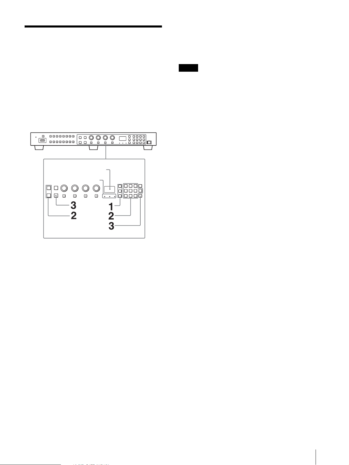
Location and Function of Parts and
Controls .......................................................... 9
Front Panel................................................................ 9
Input Signals and Adjustable/Setting Items ....... 11
Rear Panel............................................................... 13
Preventing Falling of the Monitor
(BVM-E251) .................................................. 15
Mounting the Unit in a Rack
(BVM-E171) .................................................. 15
Attaching the Handle (BVM-E171) ............. 16
Connecting the Controller (BKM-17R) ....... 16
Connecting Multiple Units with the LAN ... 17
Connecting the HDMI cable ........................ 18
Connecting the Power Cord ......................... 19
To connect the AC power cord ............................19
Turning on the Monitor ........................................19
Initial settings ............................................... 20
Setting for the LAN to Connect Multiple
Units .............................................................. 22
Selecting the Monitor (Designation of the
Monitor or Group ID Number) ................... 23
Using the Menu ............................................ 24
Menu Operation Buttons...................................... 24
Setting and Adjusting Using the Menu ...............24
Entering the Channel Number ............................27
Aborting Menu Operation ....................................27
Protection of the Setting Values .................. 28
Protecting the setting values using the
[Key Protect] ........................................................28
Protecting the setting values using
[Password] ............................................................28
Adjustment Using the Menus ...................... 28
Items ........................................................................28
[Adjustment] Menu ...............................................31
[Channel Configuration] Menu ...........................35
[Auxiliary Setting] Menu ..................................... 45
[Function Setting] Menu ...................................... 46
[System Configuration] Menu ............................ 60
[File Management] Menu .................................... 66
[System Status] Menu ........................................... 68
[Controller] Menu ................................................. 70
[Key Protect] Menu ............................................... 73
Displaying the Monitor Status Page ............ 74
Upgrading the Monitor and Controller ....... 76
Saving the Upgrade Data in a USB memory
stick, etc. ............................................................... 76
Upgrading the Monitor ........................................ 77
Upgrading the Controller .................................... 78
Extending the Monitor Function with the
Optional License (BVM-E171 only) ............. 79
Purchasing the License Purchase Key ................ 79
Obtaining the Install Key File .............................. 80
Activating the Optional License for HDR-
compatibility ........................................................ 82
Connecting the SDI Signals ......................... 83
Troubleshooting ........................................... 84
Specifications ................................................ 85
BVM-E251 ............................................................. 85
BVM-E171 ............................................................. 86
Available Signal Formats...................................... 88
Aperture Modification Frequency ...................... 93
Picture Display Size .............................................. 94
Picture Frame Display .......................................... 97
Scan Mode Image .................................................. 99
Inserting/Ejecting the USB memory stick ....... 100
Dimensions ................................................. 102
BVM-E251 ........................................................... 102
BVM-E171 ........................................................... 104
The terms HDMI and HDMI High-Definition
Multimedia Interface, and the HDMI Logo are
trademarks or registered trademarks of HDMI
Licensing Admin istrator, Inc. in th e United States an d
other countries.
Tab le of C ontents
5

Precaution
On Safety
Operate the unit only with a power source as specified
in the “Specifications” section.
A nameplate indicating operating voltage, etc., is
located on the rear panel.
Should any solid object or liquid fall into the cabinet,
unplug the unit and have it checked by qualified
personnel before operating it any further.
Do not drop or place heavy objects on the power cord.
If the power cord is damaged, turn off the power
immediately. It is dangerous to use the unit with a
damaged power cord.
Unplug the unit from the wall outlet if it is not to be
used for several days or more.
Disconnect the power cord from the AC outlet by
grasping the plug, not by pulling the cord.
The socket-outlet shall be installed near the
equipment and shall be easily accessible.
On Installation
Connecting to Other Devices
When connecting this unit to other devices, turn off this
unit and the other devices beforehand. Connecting
while turned on may cause a malfunction to this unit
and the other devices.
Handling the Screen
The OLED panel fitted to this unit is manufactured
with high precision technology, giving a functioning
pixel ratio of at least 99.99%. Thus a very small
proportion of pixels may be “stuck”, either always off
(black), always on (red, green, or blue), or flashing. In
addition, over a long period of use, because of the
physical characteristics of the organic light-emitting
diode, such “stuck” pixels may appear spontaneously.
These problems are not a malfunction.
Do not leave the screen facing the sun as it can damage
the screen. Take care when you place the unit by a
window.
Do not push or scratch the monitor’s screen. Do not
place a heavy object on the monitor’s screen. This may
cause the screen to lose uniformity.
The screen and the cabinet become warm during
operation. This is not a malfunction.
Allow adequate air circulation to prevent internal heat
build-up.
Do not place the unit on surfaces (rugs, blankets, etc.)
or near materials (curtains, draperies) that may block
the ventilation holes.
Do not install the unit in a location near heat sources
such as radiators or air ducts, or in a place subject to
direct sunlight, excessive dust, mechanical vibration or
shock.
BVM-E251
When installing the installation space must be secured
in consideration of the ventilation and service operation.
Do not block the ventilation slots, and vents of the
fans.
Leave a space around the unit for ventilation.
Leave more than 40 cm of space in the rear of the unit
to secure the operation area.
When the unit is installed on the desk or the like, leave at
least 1U (4.4 cm) of space above and below the unit.
Leaving more than 40 cm of space above the unit is
recommended in consideration of service operation.
BVM-E171
When the unit is installed in a rack, leave at least 1U (4.4
cm) of space above and below, 1.0 cm of space left and
right between the rack and the unit.
On High Brightness Display
Using the unit with the high brightness display for
extended periods may cause eyestrain or reduction of
eyesight. Be sure to take an occasional break when
using.
Follow RECOMMENDATION ITU-R BT.1702
“Guidance for the reduction of photosensitive
epileptic seizures caused by television” or other
guidelines when using.
In the HDR display, the display surface may emit heat
when high brightness images are output. Do not touch
the surface.
When [2.4(HDR)], [S-LOG3(HDR)], [S-
LOG2(HDR)], [SMPTE ST2084(HDR)], [ITU-R
BT.2100(HLG)], or [S-LOG3(Live HDR)] is selected
for [Gamma] in the [Matrix/Color Profile] menu,
images are displayed in HDR (High Dynamic Range).
In this manual, this status is described as “HDR
display.”
For details on the HDR (High Dynamic Range) display, see
page 43.
6
Precaution

On Burn-in
Due to the characteristics of the material used in the
OLED panel, permanent burn-in or reduction in
brightness may occur.
These problems are not a malfunction.
Images that may cause burn-in
Still images in the HDR display
Masked images with aspect ratios other than 16:9
Color bars or images that remain static for a long time
Character or message displays that indicate settings or
the operating state
On-screen displays such as center markers or area
markers
Images with a frame (including Multi-View displays)
For details on the HDR (High Dynamic Range) display, see
page 43.
To reduce the risk of burn-in
Turn off the character and marker displays
Press the MENU button to turn off the character
displays. To turn off the character or marker displays
of the connected equipment, operate the connected
equipment accordingly. For details, refer to the
operation manual of the connected equipment.
Do not display static images that contain high
brightness display, time codes, markers, or logos for
extended periods. Consider applying a display method
with low level signals of 100% or less.
Do not display the images with a frame for a long time.
Also, consider removing the frame during the MultiView display, or displaying the signal level of the frame
area by about 50% of the display area.
Reduce the brightness
Reduce the brightness as much as possible or reduce
the input signal level when you do not use the display.
Turn off the power when not in use
Turn off the power if the monitor is not to be used for
a prolonged period of time.
Screen saver
This product has a built-in screen saver function to
reduce burn-in. When an almost still image is displayed
for more than 10 minutes, the screen saver starts
automatically and the brightness of the screen decreases.
On a Long Period of Use
Due to an OLED’s panel structure and characteristics of
materials in its design, displaying static images for
extended periods, or using the unit repeatedly in a high
temperature/high humidity environments may cause
image smearing, burn-in, areas of which brightness is
permanently changed, lines, or a decrease in overall
brightness.
In particular, continually displaying an image smaller
than the monitor screen, such as displaying an image in
a different aspect ratio or displaying an image with a
frame, may expedite the above issues.
Avoid displaying a still image for an extended period, or
using the unit repeatedly in a high temperature/high
humidity environment such an airtight room, or around
the outlet of an air conditioner.
To prevent any of the above issues, we recommend
reducing brightness slightly, and to turn off the power
whenever the unit is not in use.
On the Surface of the Unit
The surface of the unit becomes extremely hot. Do not
touch the surface with your hand or body during power
distribution. It may cause a burn.
On Long Periods of Continuous Use
Using this unit for extended periods may cause eyestrain
or reduction of eyesight.
As soon as you feel physical discomfort or pain, stop
using this unit immediately and take a break.
If the physical discomfort or pain remains even after
taking a break, consult a physician.
Handling and Maintenance of the Screen
The surface of the screen is specially coated to reduce
image reflection. Make sure to observe the following
points as improper maintenance procedures may impair
the screen’s performance. In addition, the screen is
vulnerable to damage. Do not scratch or knock against it
using a hard object.
Be sure to disconnect the AC power cord from the AC
outlet before performing maintenance.
The surface of the screen is specially coated. Do not
attach adhesive objects, such as stickers, on it.
The surface of the screen is specially coated. Do not
touch the screen directly.
Wipe the screen surface gently with the supplied
cleaning cloth or a soft dry cloth to remove dirt.
Stubborn stains may be removed with the supplied
cleaning cloth, or a soft cloth slightly dampened with a
mild detergent solution.
The screen may become scratched if the cleaning cloth
is dusty.
Never use strong solvents such as alcohol, benzene,
thinner, acidic or alkaline detergent, detergent with
abrasives, or chemical wipe as these may damage the
screen.
Precaution
7

Use a blower to remove dust from the screen surface.
On Dew Condensation
If the unit is suddenly taken from a cold to a warm
location, or if ambient temperature suddenly rises,
moisture may form on the outer surface of the unit and/
or inside of the unit. This is known as condensation. If
condensation occurs, turn off the unit and wait until the
condensation clears before operating the unit. Operating
the unit while condensation is present may damage the
unit.
On Repacking
Do not throw away the carton and packing materials.
They make an ideal container which to transport the
unit.
Disposal of the Unit
Do not dispose of the unit with general waste.
Do not include the monitor with household waste.
When you dispose of the monitor, you must obey the
law in the relative area or country.
On Fan Error
The fan for cooling the unit is built in. When the fan
stops and the OPERATE indicator flashes in red, the
OVER RANGE indicator flashes in amber, and the
STATUS indicator lights in magenta on the front panel
for fan error indication, turn off the power and contact
an authorized Sony dealer.
About this manual
The instructions in this manual are for the following
two models:
BVM-E251
BVM-E171
The illustration of BVM-E251 is used for the
explanations. Any differences in specifications are
clearly indicated in the text.
The controller for operating this unit used for the
explanation is the BKM-17R. When you use the BKM16R, refer to the operating instructions of BKM-16R.
8
Precaution
Location and Function of Parts and Controls
Notes
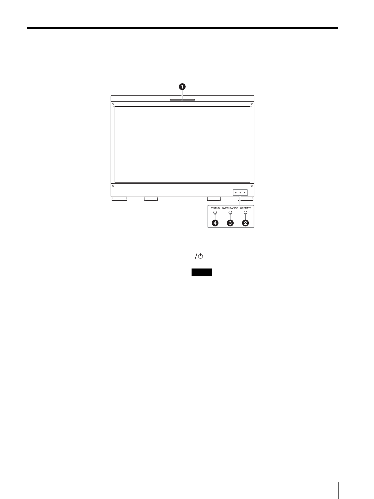
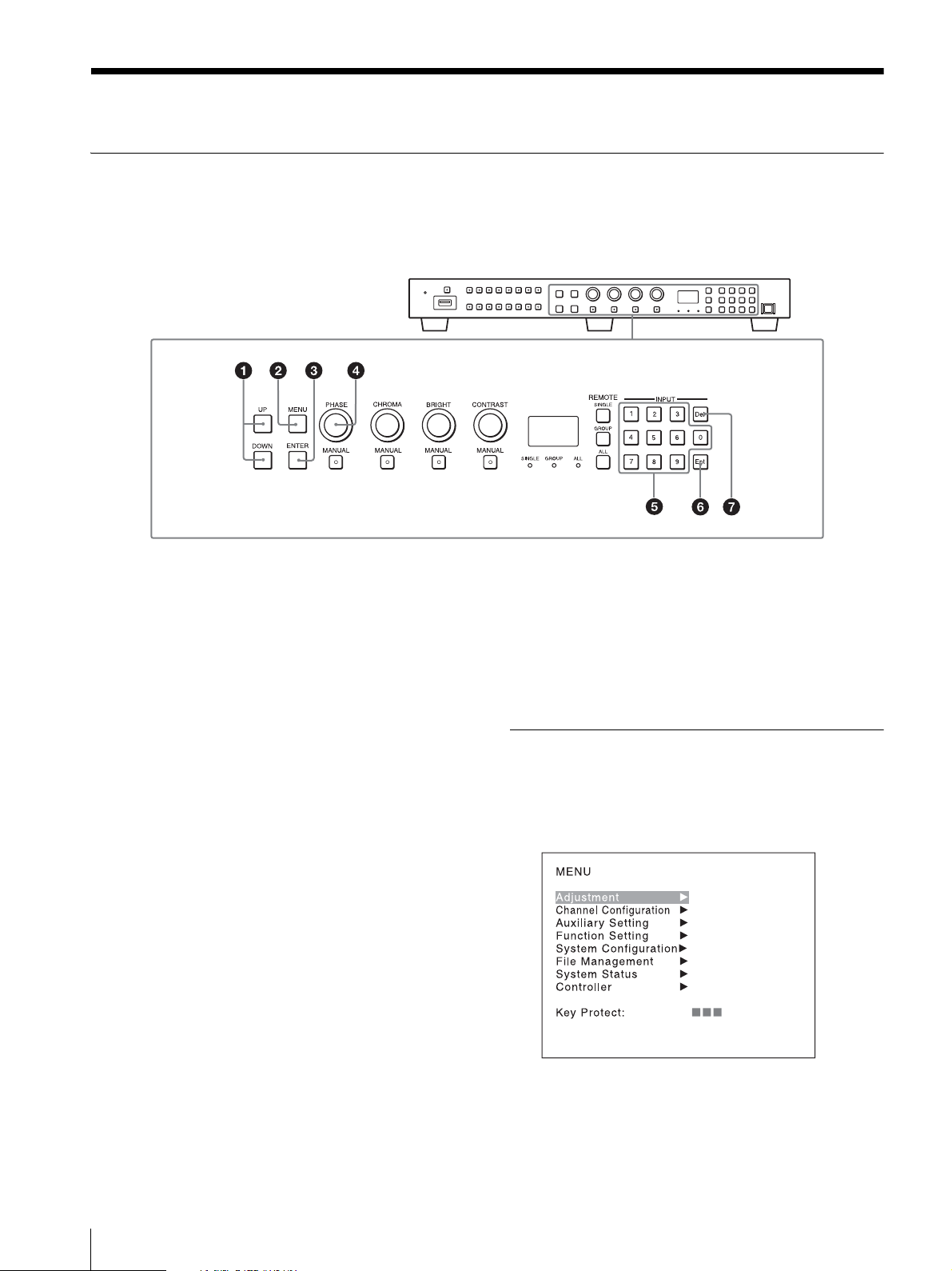
Front Panel
Tally lamp
With factory settings, the tally lamp lights when pins No.
5 and No. 8 of the PARALLEL REMOTE connector on
the rear panel are shorted. By changing the setting in the
[Parallel Remote] menu (page 61) of the [System
Configuration] menu, different pins on the PARALLEL
REMOTE connector can be used to control the tally
lamp.
OPERATE indicator
When the power switch (on the rear panel) is turned on,
internal data initialization starts and the OPERATE
indicator flashes in red for a while. When the signal is
output, the indicator flashes in green to indicate that
data initialization continues. When initialization is
finished and the monitor enters its operation mode, the
indicator lights in green.
The OPERATE indicator is lit in red when the monitor
is in sleep mode.
The monitor will be in sleep mode under the following
conditions:
[Sleep Mode] is set to [On] in the [Power] menu
(page 62) of the [System Configuration] menu and the
power switch (on the rear panel) is turned on. (The
OPERATE indicator will flash for initialization after
the switch is turned on, then will light.)
The monitor is changed from operation mode to
sleep mode by external control.
Lights in green when the monitor is put into operation
mode from sleep mode by pressing the MONITOR
switch of the controller.
When the OPERATE indicator is flashing in red, the
monitor cannot be put into operation mode. Wait until
the indicator is steadily lit.
When the OPERATE indicator is flashing in green, the
monitor is not in full operation mode and images
cannot be displayed correctly. Wait until the indicator
is steadily lit in green.
The OPERATE indicator may indicate an error or
warning. For details, see “About error/warning signals of
the indicator” (page 10).
OVER RANGE indicator
Lights in amber when ABL (Automatic Brightness
Limiter) starts, and [ABL] is displayed at the bottom left
of the screen. For details, see [ABL Notification]
(page 65). Also, lights in amber when the signal level
exceeds the dynamic range of the signal processing
circuit in the following circumstances.
– when the monitor is not in the HDR display
– when an item other than [S-LOG2(SDR)] or [SLOG3(SDR)] is selected
Decrease the contrast or brightness when the OVER
RANGE indicator is lit.
Location and Function of Parts and Controls
9

The OVER RANGE indicator may indicate an error or
warning. For details, see “About error/warning signals of
the indicator” (page 10).
STATUS indicator
Slowly flashes in yellow when the screen saver is
activated, and quickly flashes in yellow when a warning
during startup occurs.
Lights in blue in the HDR display. Slowly flashes in blue
when the screen saver is activated in the HDR display,
and quickly flashes in blue when a warning during
startup occurs.
The STATUS indicator may indicate an error or warning.
For details, see “About error/warning signals of the
indicator” (page 10).
Warning display
STATUS
indicator
–Flashes in
– Lights in
––Flashes in
–: Status except for error display.
OVER
RANGE
indicator
amber
amber
1)
OPERATE
indicator
– The luminance is
– ABL activation or
amber
Symptom
reduced to protect
the panel from an
increase of
temperature in the
panel part.
over range
DC input voltage is
decreased.
About error/warning signals of the indicator
The OVER RANGE indicator, OPERATE indicator, and/
or STATUS indicator on the front panel may show an
error or warning while the monitor is being operated.
If the error or warning is shown, please contact your
Sony representative.
Error display
STATUS
indicator
Lights in
yellow
Lights in
yellow
Flashes in
yellow
Flashes in
yellow
Lights in
magenta
Flashes in
magenta
––Lights in
Lights in
magenta
OVER
RANGE
indicator
Lights in
amber
Flashes in
amber
Lights in
amber
Flashes in
amber
Flashes in
amber
Lights in
amber
Lights in
amber
OPERATE
indicator
Flashes in
red
Flashes in
red
Flashes in
red
Flashes in
red
Flashes in
red
Flashes in
red
amber
Flashes in
red
(quickly)
Symptom
The power in the
panel part is
unusual.
The temperature in
the panel part is
unusual.
The ambient
temperature sensor
is unusual.
Error at restarting.
Fan error.
Device error.
DC input voltage is
unusual.
HDMI EDID error
1) For the indicator display when the [Over Range] function is enabled,
see page 65.
10
Location and Function of Parts and Controls

Input Signals and Adjustable/Setting Items
Item
CONTRAST
BRIGHT
CHROMA
PHASE
Picture Auto Adjust
NTSC Setup Level
Position Adj
Gamut Error Display
Scan Mode
Native Scan
(×1, ×2)
Native Scan
(Aspect Correction)
16:9
H Delay
V Delay
Char Off
Color Temp
Status
Ape rture
Mono
Blue Only
R Off
G Off
B Off
Chroma Up
Interlace
Pixel Zoom
Capture
Capture Load
Marker
Aspect Marker
Area Marker 1
Area Marker 2
Center Marker
Aspect Marker-Line
Aspect Blanking-Half
Aspect Blanking-Black
Side by Side
Wi pe
Butterfly
15)
15)
2)
10)
Analog SDI HDMI
Composite SD 3G/HD
YCbCr YCbCr RGB XYZ
××
ЧЧЧЧЧ
(NTSC)
ЧЧЧЧЧ
ЧЧЧЧЧ
(NTSC)
13)
ЧЧЧЧЧ
×
13)
××× 6)
× ×
× ×
××
See “Picture Frame Display” on page 97.
×××
Input signal
3)
7)
1)
4)
×
4)
1)
5) 8)
7)
8)
8)
8)
8)
8)
8)
8)
8)
8)
9)
Location and Function of Parts and Controls
11

Item
Blending
Error Notify Clear
Audio Level Meter
ALM Hold Reset
Time C ode
Flicker Free
Closed Caption
: Adjustable/can be set
11)
11)
16)
Analog SDI HDMI
Composite SD 3G/HD
×
× ×
× ×
× ×
×
× : Not adjustable/cannot be set
1) Does not function when the RGB signal with the
quantization range set to Full is selected. It functions,
however, if [Gamma] is set to [S-LOG2(SDR)] or [SLOG3(SDR)] in the [Color Profile] menu.
2) Fixed to [×1] when the HD signal or the computer signal
of HDMI is input.
3) Fixed to [16:9] with 720P input signal.
4) Becomes [1.896:1] with 2048 × 1080 input signal.
5) Excludes 640 × 480/60*P. Fixed to [16:9] with 1280 × 720/
50P, 60*P. (* Also compatible with 1/1.001.)
6) In effect with SD format
7) Functions when the YCbCr signal is input.
8) Does not function when the computer signal of HDMI is
input.
9) Functions when the [HDMI Auto] menu (page 38) of the
[Screen Aspect] menu is set to [Off].
10) For the operable input signal, see “Aperture Modification
Frequency” (page 93).
11) Sets when the SDI signal is input
12) Enabled only when the signal system is 480/59.94i.
13) When the composite signal is input and [Under Scan] is
selected, the blanking area of the horizontal direction is
masked.
14) Enabled during HD-SDI only
15) Does not function when the software version is 1.1 or later,
and [Gamma] is set to [S-LOG3(SDR)], [S-LOG2(SDR)],
[S-LOG3(HDR)], [S-LOG2(HDR)], [SMPTE
ST2084(HDR)], [ITU-R BT.2100(HLG)], or [SLOG3(Live HDR)].
16) Cannot be selected in the HDR display. [On] is always set
for signals of vertical frequency 24 Hz, 25 Hz, 48 Hz, and
50 Hz. [Off] is always set for signals of 30 Hz and 60 Hz.
Input signal
YCbCr YCbCr RGB XYZ
12)
14)
1)
×××
×
1)
12
Location and Function of Parts and Controls
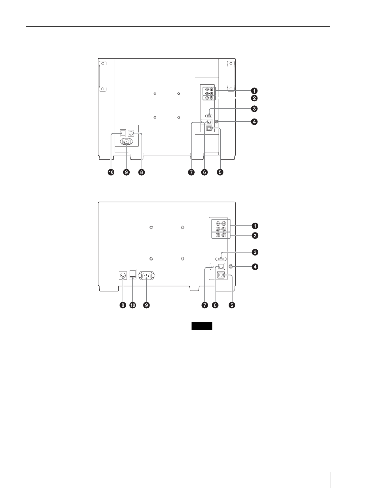
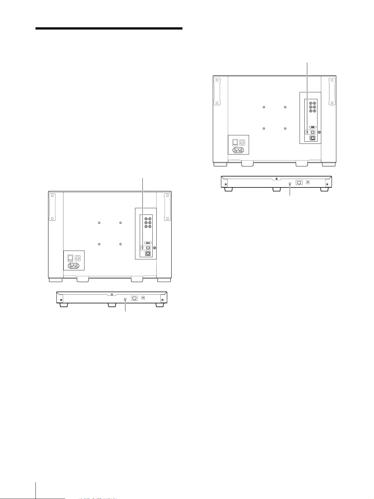
Rear Panel
Notes
BVM-E251
BVM-E171
SDI input and output connectors (BNC)
SDI 1 IN connector
Input connector for serial digital signals.
SDI 2 IN connector
Input connector for serial digital signals.
MONITOR OUT connector
MONITOR OUT for SDI 1 IN and SDI 2 IN
connectors.
COMPOSITE input and output connectors
IN connector
Input connector for composite video signals.
OUT connector
Loop-through output connector.
(BNC)
When the composite signal is used, adjust the signal
level in the [Picture Adj] menu (page 31).
When inputting a video signal with the jitters, etc.
the picture may be disturbed. We recommend using
the TBC (time base corrector).
When the unit is turned off, the signal wave of the
COMPOSITE input and output connectors may be
distorted.
HDMI IN (HDMI input) connector
Input connector for HDMI
1)
signals.
HDMI (High-Definition Multimedia Interface) is an
interface that supports both video and audio on a single
digital connection, allowing you to enjoy high quality
digital picture and sound. The HDMI specification
supports HDCP (High-bandwidth Digital Content
Location and Function of Parts and Controls
13
Protection), a copy protection technology that
Note
CAUTION
incorporates coding technology for digital video signals.
1) The terms HDMI and HDMI High-Definition Multimedia
Interface, and the HDMI Logo are trademarks or
registered trademarks of HDMI Licensing Administrator,
Inc. in the United States and other countries.
The HDMI audio signal is not available for this monitor.
Use HDMI compliant cable (sold separately), Category 2
(High Speed HDMI Cable), with HDMI logo.
DC 12V OUT connector (female)
Supplies the DC power to the controller.
Connect to the DC 12V connector of the controller with
the SMF-17R20 or the cable supplied with the BKM37H/38H/39H.
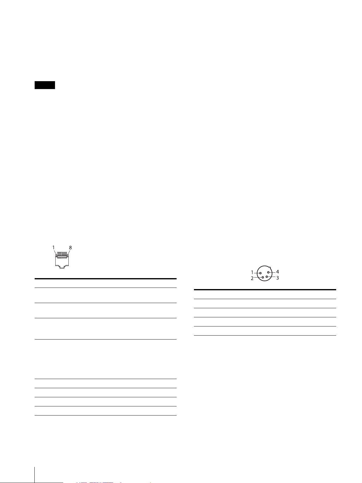
PARALLEL REMOTE connector (RJ-45, 8-pin)
Forms a parallel switch and controls the monitor
externally.
Wiring required to use the Remote Control
Connect the function you want to use with a Remote
Control to the Ground (Pin 5).
LAN (10/100) connector
Connect to the LAN (10/100) connector of the
controller by using the SMF-17R20 or the cable supplied
with the BKM-37H/38H/39H. Or connect to the
network or the LAN (10/100) connector of the controller
by using a 10BASE-T/100BASE-TX LAN cable
(shielded-type, sold separately).
CAUTION
For safety, do not connect the connector for peripheral
device wiring that might have excessive voltage to this
port. Follow the instructions for this port.
When you connect the LAN cable of the unit to
peripheral device, use a shielded-type cable to prevent
malfunction due to radiation noise.
The connection speed may be affected by the network
system. This unit does not guarantee the
communication speed or quality of 10BASE-T/
100BASE-TX.
For safety, do not connect the connector for peripheral
device wiring that might have excessive voltage to this
port. Follow the instructions for this port.
Pin assignment
Pin number Functions
1 Designating input signal channel 1
(numeric keypad function)
2 Designating input signal channel 2
(numeric keypad function)
3 Marker (set in the [Marker Setting]
menu) On/Off (MARKER button
function)
4 Selecting whether monochrome image
is displayed or the monitor switches the
display mode automatically between
color image and monochrome image
depending on the input signal (MONO
button function).
5GND
6 Not connected
7 Not connected
8 Tally lamp On/Off
NETWORK switch
LAN: When connecting to the network.
PEER TO PEER: When connecting to the LAN (10/100)
connector of the controller in 1 to 1 connection.
DC IN 24V – 28V (DC power input) connector
(XLR 4-pin, male)
Connect the 24V to 28V DC power supply.
Pin number Functions
1– (GND)
2NC
3NC
4 + (DC 24V – 28V)
AC IN connector (3-pin)
Connects the monitor to an AC power source, via the
supplied AC power cord.
Power switch
When turned on, the monitor enters operation mode. By
setting in the [Power] menu (page 62) of the [System
Configuration] menu, the monitor can also be set to
enter sleep mode when the power switch is turned on.
14
You can assign functions using the [Parallel Remote]
menu (page 61) of the [System Configuration] menu.
Location and Function of Parts and Controls
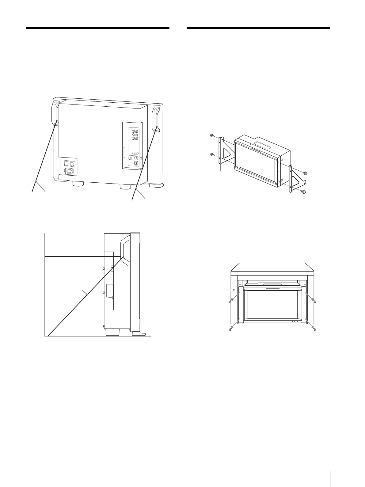
Preventing Falling of the
String
String
String
Rack mount
bracket
Screws (supplied)
Rack
Mounting the Unit in a
Monitor (BVM-E251)
1
Tie a piece of stout string (commercially available)
to the left and right handles of the monitor.
2
Secure the ends of the string to the floor or wall.
Rack (BVM-E171)
To mount the unit in an EIA standard 19-inch rack, use
the supplied rack mount brackets and screws.
1
Remove the four feet from the bottom of the unit.
2
Attach the rack mount brackets to each side of the
unit with the supplied screws.
3
Screw the rack mount brackets to the rack to mount
the unit.
Use the commercially available screws that match
the size of the rack’s holes.
Preventing Falling of the Monitor (BVM-E251) / Mounting the Unit in a Rack (BVM-E171)
15
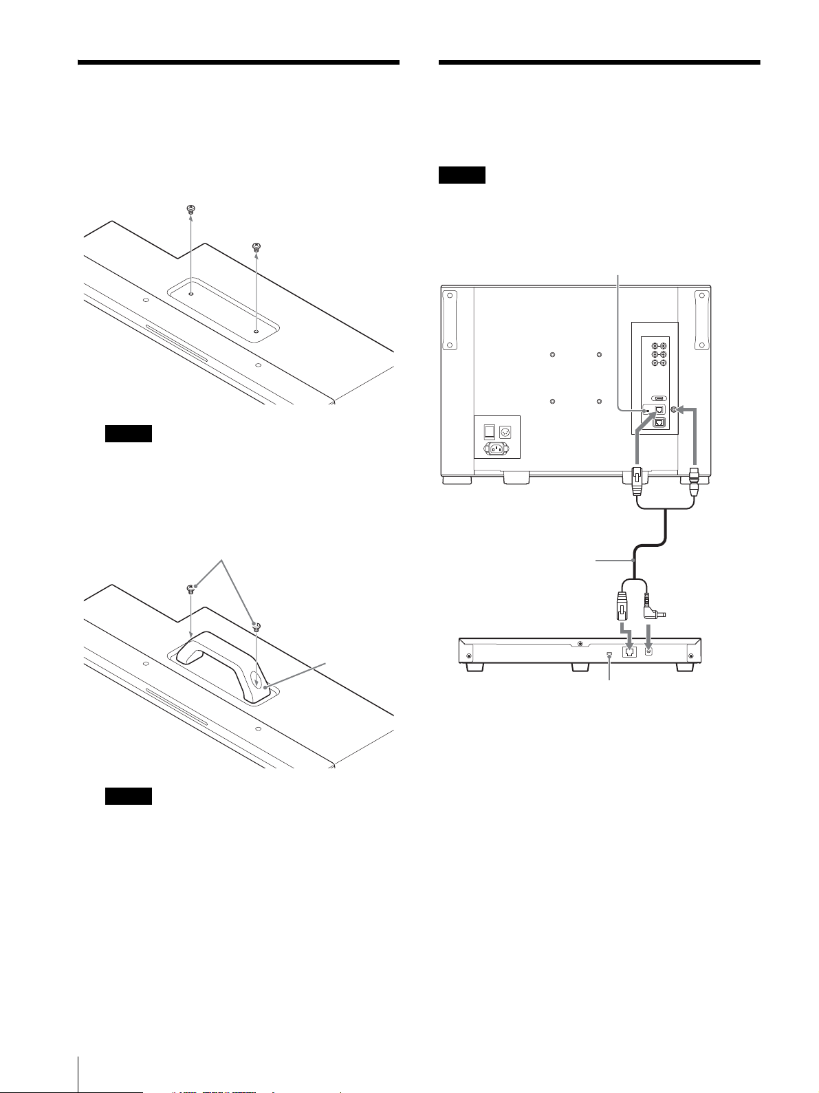
Attaching the Handle
Note
Notes
Note
Screws (supplied)
Handle
(supplied)
NETWORK switch:
Set to PEER TO PEER.
LAN (10/100)
connector
DC 12V OUT
connector
LAN (10/100)
connector
DC 12V connector
SMF-17R20, etc.
Controller
(BKM-17R)
NETWORK switch:
Set to PEER TO PEER.
Connecting the Controller
(BVM-E171)
1
Remove the 2 screws on the top side.
Keep the removed screws in a safe place to prevent
them from being lost.
2
Attach the handle with the supplied screws.
(BKM-17R)
When you connect the BKM-16R, refer to the operating
instructions of BKM-16R.
Make sure that the screw clamp is not loosened.
Secure the handle attachment.
1
Turn off the power switch of the monitor before
connecting the units.
2
Set the NETWORK switches of the monitor and the
controller to PEER TO PEER.
3
Connect the LAN (10/100) connector of the
monitor and the LAN (10/100) connector of the
controller by using the SMF-17R20 or the cable
supplied with the BKM-37H/38H/39H, or a
10BASE-T/100BASE-TX straight LAN cable
(shielded-type, sold separately).
4
Connect the DC 12V OUT connector of the
monitor and DC 12V connector of the controller by
using the SMF-17R20 or the cable supplied with the
16
Attaching the Handle (BVM-E171) / Connecting the Controller (BKM-17R)
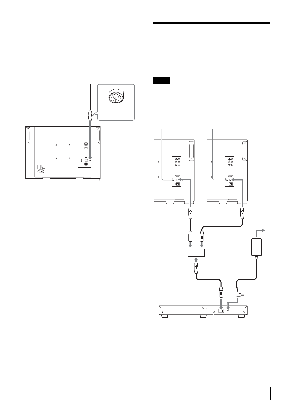
BKM-37H/38H/39H. Or connect the output cable
Notes
Fit the shape of the
connector.
NETWORK switch:
Set to LAN.
NETWORK switch:
Set to LAN.
LAN (10/100)
connector
LAN (10/100)
connector
Switching hub
(recommended:
with AUTO MDI/
MDI-X function)
AC adaptor
(supplied with the
BKM-17R)
LAN (10/100)
connector
DC 12V
connector
Controller
(BKM-17R)
NETWORK switch:
Set to LAN.
of the AC adaptor supplied with the controller to
the DC 12V connector of the controller.
Note on connecting the cable to the DC 12V
OUT connector
Insert the connector so as to fit the shape of the DC 12V
OUT connector.
Connecting Multiple Units with the LAN
The controller controls up to 32 monitors. Up to three
controllers are connected to one monitor in single mode.
The controller cannot control monitors in another
subnetwork.
When you connect the BKM-16R, refer to the
operating instructions of BKM-16R.
1
Turn off the power switch of the monitor before
connecting the units.
Connecting Multiple Units with the LAN
17
2
Note
Note
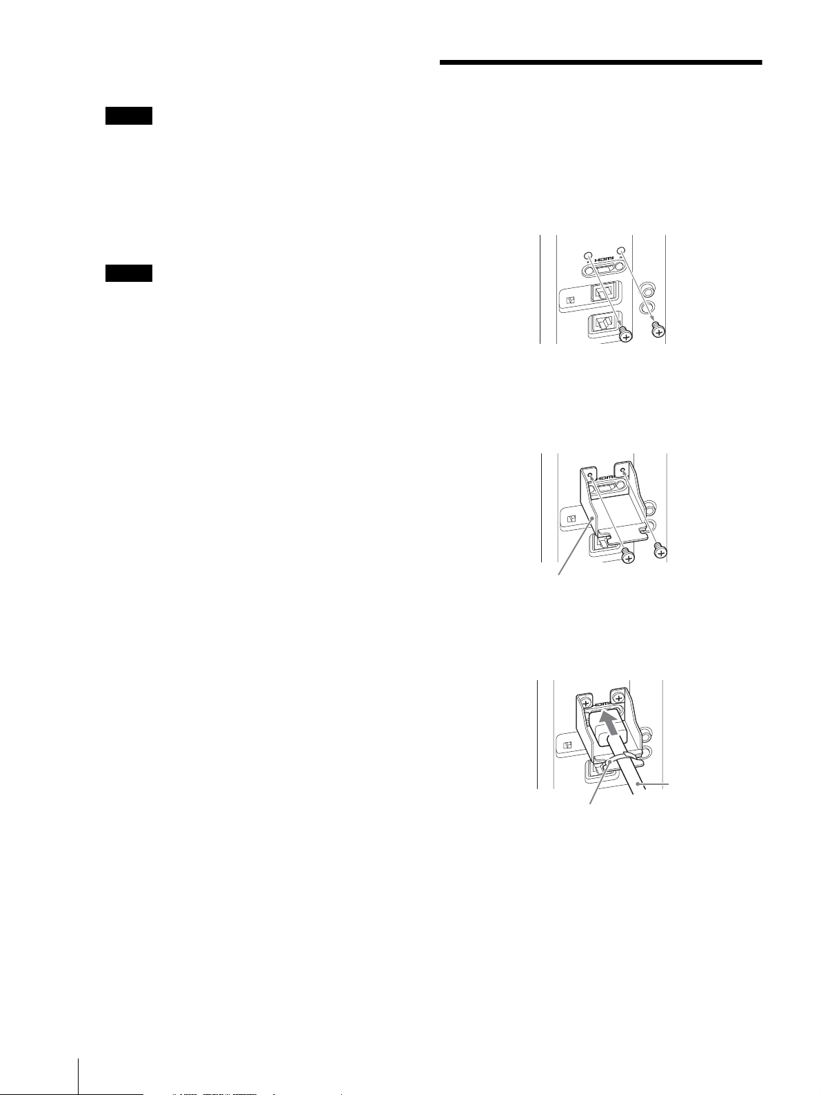
HDMI cable holder (supplied)
Cable fixer
HDMI cable
Connect to the network by using a 10BASE-T/
100BASE-TX cable (shielded-type, sold separately).
We recommend to use an optional switching hub
with auto selection function (AUTO MDI/MDI-X)
of a straight/cross cable.
3
Connect the output cable on the AC adaptor
supplied with the controller to the DC 12V
connector of the controller.
When multiple units are connected, set for the LAN
before setting the NETWORK switch to LAN
(page 22).
4
Set the NETWORK switches of each monitor and
the controller to LAN.
Connecting the HDMI cable
1
Remove the two screws on both sides of the HDMI
IN connector.
2
Attach the HDMI cable holder (supplied) with the
removed screws.
3
Insert the HDMI cable and fix with a commerciallyavailable cable fixer (1 piece).
18
Connecting the HDMI cable
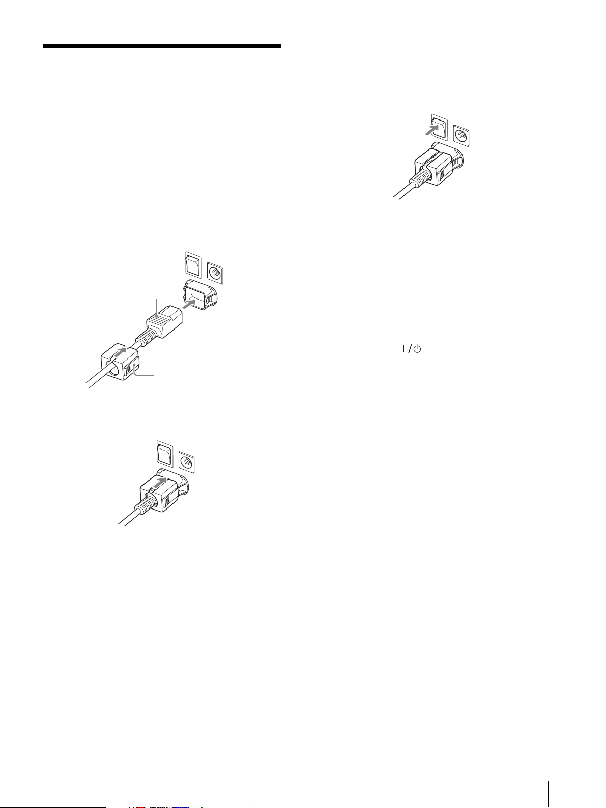
Connecting the Power
AC IN connector
AC power cord (supplied)
AC plug holder
(supplied)
Cord
You can operate the monitor with AC or DC power
supply.
To connect the AC power cord
1
Plug the AC power cord into the AC IN connector
on the rear panel then attach the AC plug holder
(supplied) to the AC power cord.
Turning on the Monitor
Press the power switch on the rear panel to turn on the
power.
When you turn on the monitor for the first time after
purchasing it, the [Select Area] screen is displayed. Select
the area where you intend to use this monitor.
For selecting the area, see page 20.
The warm-up time is more than 30 minutes,
approximately.
When the monitor is in sleep mode
As the OPERATE indicator lights in red in sleep mode,
press the MONITOR switch of the controller.
The OPERATE indicator lights in green and the monitor
enters operation mode.
2
Slide the AC plug holder over the cord until it locks.
To remove the AC power cord
Pull out the AC plug holder while pressing the lock
levers.
To connect the DC power supply
Connect the DC power supply to the DC IN 24V - 28V
connector.
When the AC power cord and DC power supply are
connected, the AC power supply is given preference over
the DC power supply. To use the DC power supply,
disconnect the AC power cord.
Connecting the Power Cord
19
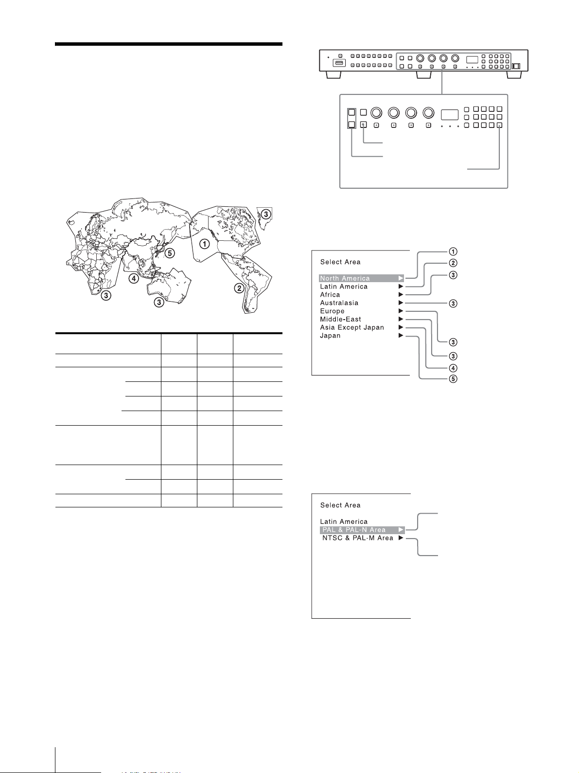
Initial settings
ENTER button
UP/DOWN buttons
Ent button
North America
Latin America
Africa
Australia/New Zealand
Europe/Russia
Middle East
Asia Except Japan
Japan
PAL &PAL- N ar ea
NTSC&PAL-M area
When you turn on the monitor for the first time after
purchasing it, select the area where you intend to use this
monitor from among the options.
When the area is selected, the menu item settings
suitable for the selected area are applied.
Default value for each area
1
Turn on the monitor with the power switch.
The [Select Area] screen appears.
[Color
Tem p]
[North America] [D65] [7.5%] [ITU-R BT.709]
[Latin America]
[PAL & PAL-N Area]
[NTSC & PAL-M Area]
[Afri ca]
[Australasia]
[Europe]
[Middle-East]
[Asi a Except Japa n]
[Japan] [D93] [0%] [ITU-R BT.709]
Argentina [D65] [0%] [ITU-R BT.709]
Paraguay [D65] [0%] [ITU-R BT.709]
Uruguay [D65] [0%] [ITU-R BT.709]
Other A rea [D65] [7.5%] [ITU-R BT.709]
[D65] [0%] [ITU-R BT.709]
[NTSC Area ] [D65] [7.5%] [ITU-R BT.709]
[PAL Area] [D65] [0%] [ITU- R BT.709]
[Setup
Level]
[Color Profile]
Note on the setting of color temperature
If you measure the color temperatures of different
display types, such as CRT, LCD, or OLED, by using a
common (or general) color ana lyz er t hat is base d on CIE
1931, and adjust the xy chromaticity to the same value,
the appearance may be different because of optical
spectrum differences.
To compensate for this difference, the [D93], [D65],
[D61], [D55], and [User1] to [User5] settings (except
[DCI]) of the monitor are adjusted by an offset
1) The offset value applied (x-0.006, y-0.011) is based on the
Judd’s function to the CIE 1931 (x, y) value.
1)
.
2
Press the UP or DOWN button of the controller to
select the area where you intend to use the monitor
and press the ENTER (Ent) button.
If you select either [Latin America] or [Asia Except
Japan], one of the following screens appears.
If [Latin America] is selected:
Select [PAL & PAL-N Area] or [NTSC & PAL-M
Area], and press the ENTER (Ent) button.
If [Asia Except Japan] is selected:
20
Initial settings
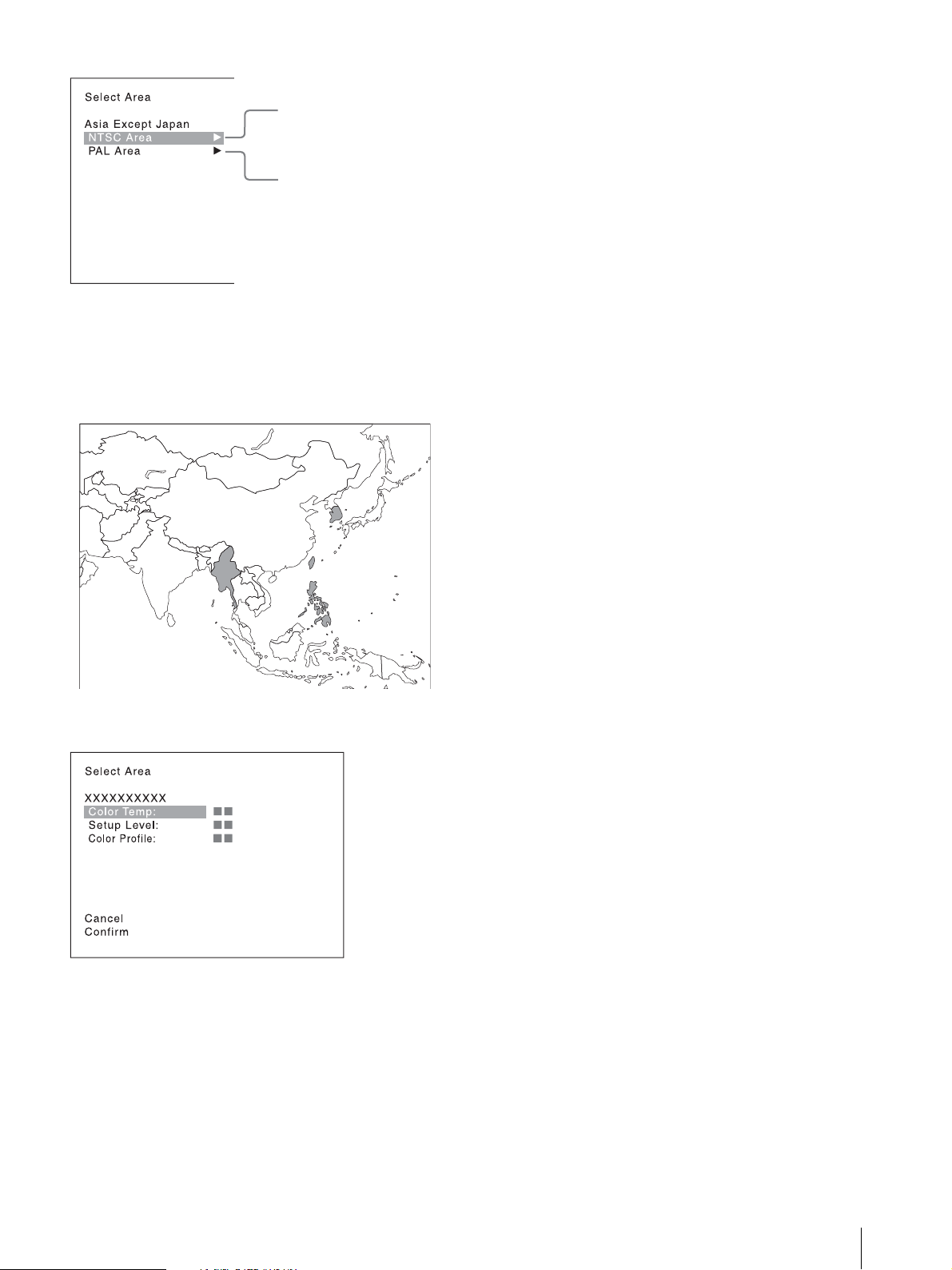
Customers who will use this monitor in the shaded
NTSC area
PAL are a
areas shown in the map below should select [NTSC
Area].
Other customers should select [PAL Area].
Then press the ENTER (Ent) button.
[Setup Level] ([NTSC Setup Level]: page 37)
[Color Profile] (page 39)
3
Confirm the settings.
[Cancel]: Select to cancel the setting and return to
the Select Area screen.
[Confirm]: Select to save the setting and end
selecting the area.
See “Default value for each area” on page 20 on the
setting value.
After saving and reflecting the setting, you can change
the setting with the menu.
[Color Temp] (color temperature) (page 36)
Initial settings
21
Setting for the LAN to
NETWORK switch:
Set to PEER TO PEER.
NETWORK switch:
Set to PEER TO PEER.
BKM-17R
NETWORK switch:
Set to LAN.
NETWORK switch:
Set to LAN.
BKM-17R
Connect Multiple Units
You can control the multiple monitors using the
controller (BKM-17R, sold separately) connected via
each LAN (10/100) connector. You can also control a
specific monitor or monitor group.
Set an IP address to the monitors and controller and a
monitor ID number and group ID number to each
monitor.
1
Set the NETWORK switches of each monitor and
the controller to PEER TO PEER.
4
Set the NETWORK switches of the monitor and the
controller to LAN.
22
2
Set the different IP address to each monitor and the
controller.
Monitor: Set the IP address in the [Network
Setting] menu (page 60) of the [System
Configuration] menu.
Controller: Set the IP address in the [Network
Setting] menu (page 70) of the [Controller] menu.
3
Set [Monitor ID] and [Group ID] in the [Network
Setting] menu (page 60) of the [System
Configuration] menu.
Set the different monitor ID number to each
monitor and if necessary, group ID number.
You can use the numbers 1 to 99 as a monitor ID
number or group ID number.
Setting for the LAN to Connect Multiple Units
Selecting the Monitor
Notes
Display window
Indicator
(Designation of the
Monitor or Group ID
3
Press the ENTER (Ent) button to confirm the
setting.
The monitor ID number, group ID number, or ALL
is displayed in the display window.
Number)
When the multiple monitors are connected by network
connections, you can remotely connect the monitors
from the controller by designating the set monitor ID
number or group ID number.
When the monitor with no assigned monitor ID
number or group ID number is selected, the setting is
not changed and the previous connection status is
maintained
When there are monitors with the same ID number,
the monitor with the lower IP address is selected.
Even if a different monitor ID number is set to the
monitors, when the same IP address is set to another
monitor, the monitor cannot be connected to the
network.
1
Press the corresponding button to select the
connection mode.
SINGLE button: Selects single connection mode.
The designated monitor is connected remotely.
The monitor ID number is displayed on all
connected monitors when the button is held down.
GROUP button: Selects group connection mode.
The monitor of the designated group is connected
remotely.
The group ID number is displayed on all connected
monitors when the button is held down.
ALL button: Selects all connection modes.
All monitors are connected remotely.
The indicator corresponding to the pressed button
flashes and lights after recognizing the monitor.
2
Select the monitor ID number for the single
connection mode or group ID number for the
group connection mode by pressing the UP/
DOWN or numeric button.
Up to 99 is entered as the monitor ID or group ID
number.
Selecting the Monitor (Designation of the Monitor or Group ID Number)
23
Using the Menu
Controller (BKM-17R)
Menu Operation Buttons
The menu is operated using the menu operation buttons
on the controller (BKM-17R, sold separately)
The functions of the menu operation buttons are
described below.
UP /DOWN buttons
UP button: Moves the cursor upward. In setting
mode, increases the setting or adjustment value.
DOWN button: Moves the cursor downward. In
setting mode, decreases the setting or adjustment
value.
MENU button
Displays the menu. Goes back to the menu of the upper
level. (On the main menu, goes back to the normal
picture.)
You can also operate the unit using the BKM-16R in the
same way.
Ent button
Changes an item or displays the information on the
input signal, etc. In setting mode, confirms the
adjustment or setting value.
Del button
Deletes the values and characters entered.
Setting and Adjusting Using the Menu
1
Press the MENU button.
The main menu is displayed on the screen.
ENTER button
Changes an item or displays the information on the
functi ons assigned t o fu nct ion buttons. In setting mod e,
confirms the adjustment or setting value.
PHASE knob
By turning this knob clockwise, the cursor moves
downward. In setting mode, increases the setting or
adjustment value (has the same function as the UP
button).
By turning this knob counterclockwise, the cursor
moves upward. In setting mode, decreases the setting or
adjustment value (has the same function as the DOWN
button).
Numeric buttons
Enters the numerical values
24
Using the Menu
When you select one item on the main menu, the
level 1 menu of the selected item appears.
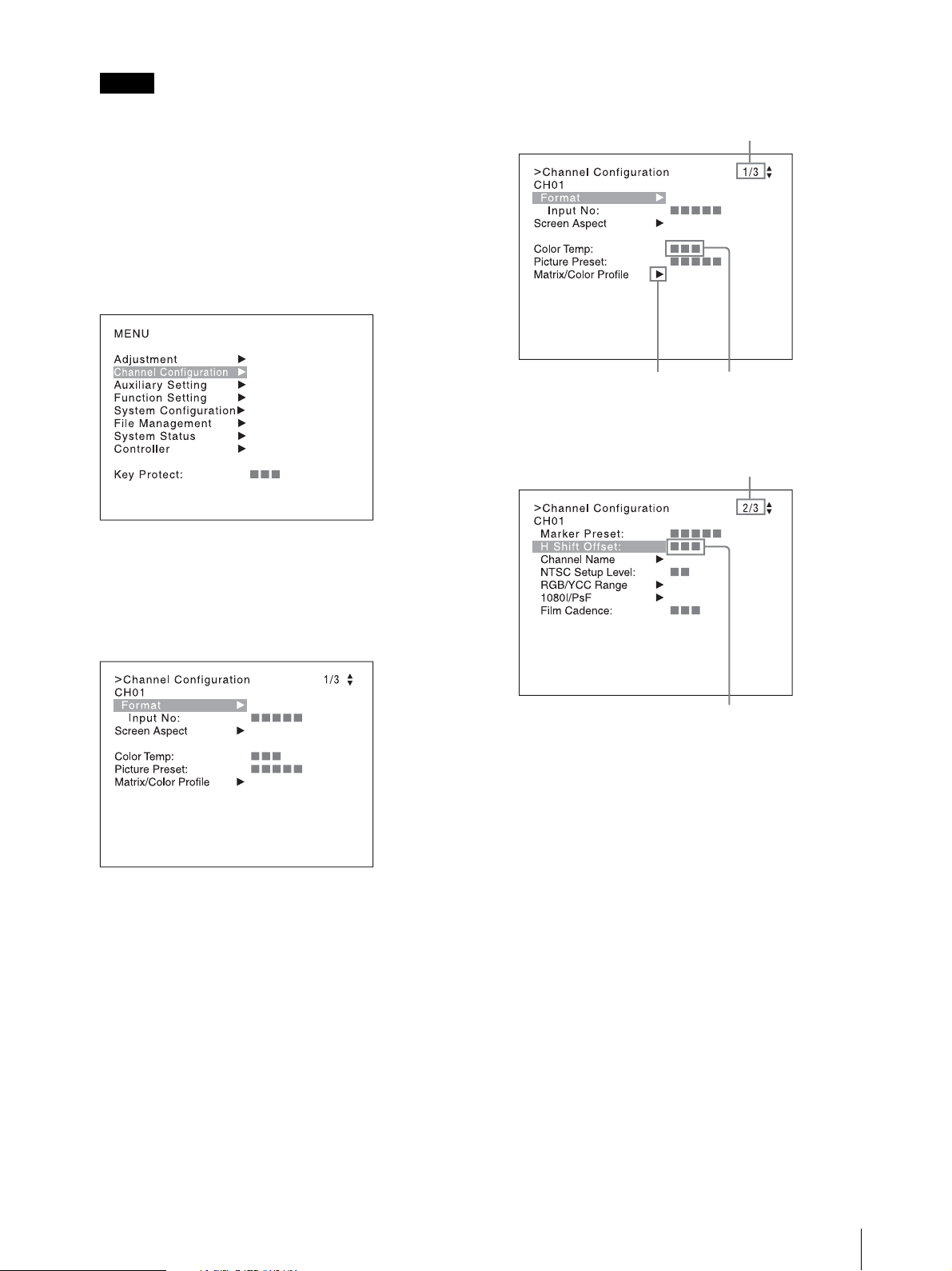
Notes
The menu disappears automatically if not
Indicates that the menu continues
onto next page.
Indicates that this item has
sub-list. You can go to the
lower level.
Chooses the setting value.
Indicates that the menu is continued
from previous page.
Enters numerical values.
operated for about one minute.
Menu items displayed in gray cannot be selected.
This menu is not displayed when [Pixel Zoom] is
set to on.
2
Using the UP or DOWN button or PHASE knob,
select the desired item. (Example: select the
[Channel Configuration] menu by pressing the
DOWN button.)
Display example
3
Press the ENTER or Ent button
Level 1 of the selected menu is displayed.
The current settings are displayed in place of the
marks on the illustrations of the menu screen.
4
Repeat steps 2 and 3 until the desired menu is
displayed.
For more information about setting and
adjustments, see below.
Choosing the setting value
The method for selecting the value is different due to the
menu item.
Selecting in setting mode
Selecting from the setting list
When selecting in setting mode
1
Using the UP or DOWN button or PHASE knob,
select the desired item and press the ENTER or Ent
button.
The cursor moves to the setting value and the
monitor enters in setting mode.
Using the Menu
25
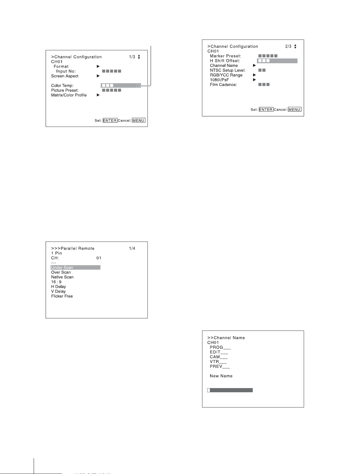
Display example
Cursor
2
Using the UP or DOWN button or PHASE knob,
select the setting value.
3
Press the ENTER or Ent button.
The setting is confirmed and the cursor returns to
the item.
Display example
2
Select the value in one of the following three ways:
Enter the value directly using the numeric
buttons and press the ENTER or Ent button. (only
the item with a value of setting range over 0)
Select the value using the UP or DOWN button.
Select the value using the PHASE knob.
3
Press the ENTER or Ent button.
When selecting from the setting list
1
Using the UP or DOWN button or PHASE knob,
select the desired item in the setting list.
Display example
2
Press the ENTER or Ent button.
The setting is confirmed and the display returns to
the menu of the upper level.
The setting is confirmed and the cursor returns to
the item.
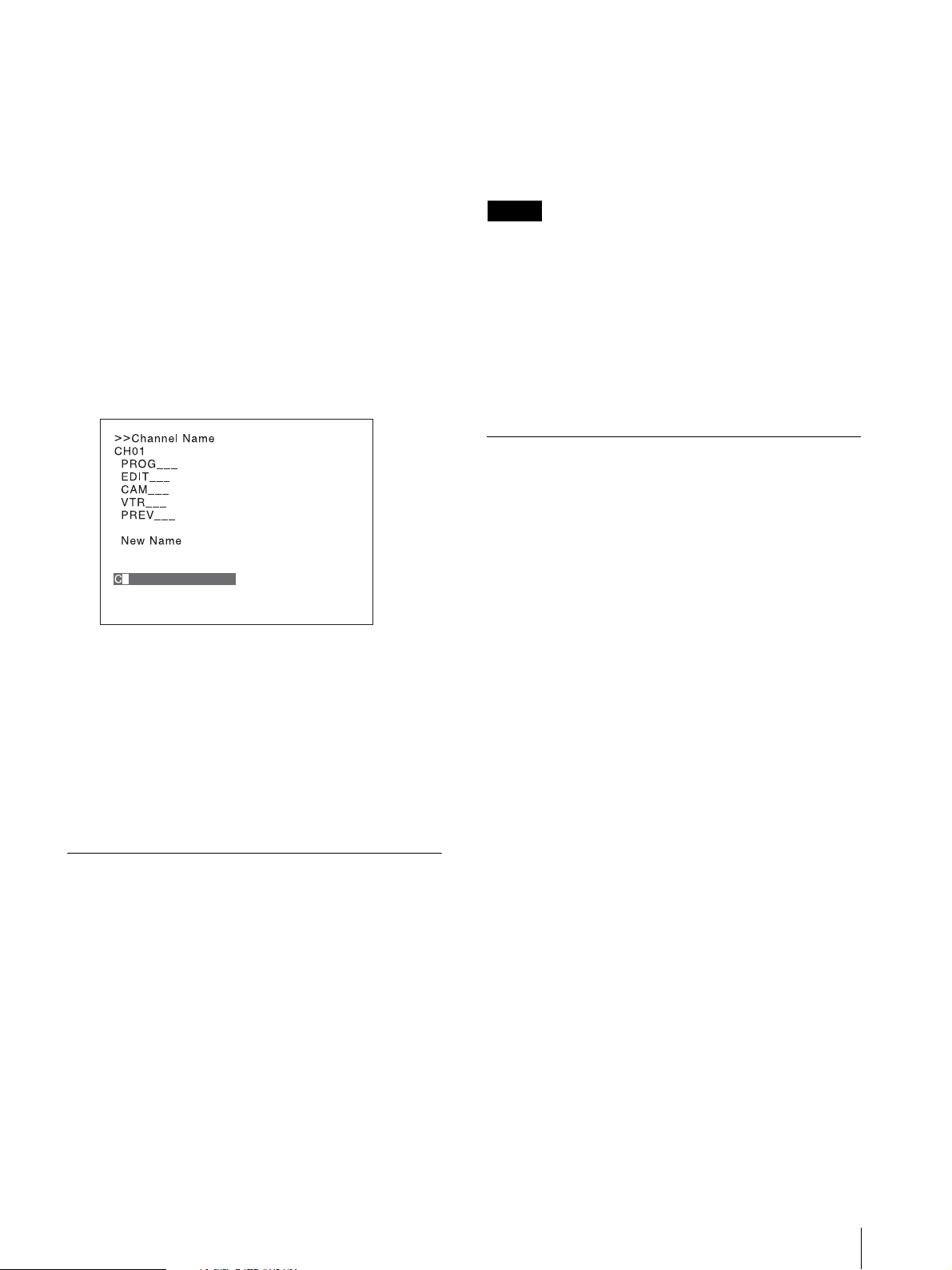
Entering characters
1
Using the UP or DOWN button or PHASE knob,
select [New Name] or the existing name.
The “---“ means that one or more characters can be
entered in sequence after the existing name.
2
Press the ENTER or Ent button.
3
Using the UP or DOWN button or PHASE knob,
select the characters that you wish to enter.
Display example
Entering numerical values
1
Using the UP or DOWN button or PHASE knob,
select the desired item and press the ENTER or Ent
button.
The cursor moves to the setting value and the
monitor enters in setting mode.
26
Using the Menu
When you press the UP button or turn the PHASE
knob clockwise, the characters and symbols appear
in the sequence shown below.
Capital letters (A B ....... Y Z)
Note
Lower-case letters (a b ....... y z)
Numbers (0 1 ....... 8 9) Marks
Capital letters...
When you press the DOWN button or turn the
PHASE knob counterclockwise, the characters and
symbols appear in the reverse sequence described
above.
The usable symbols are limited depending on the
menu.“(space)” is not used as a first character of a
sentence.
4
Press the ENTER or Ent button.
The selected character is entered.
Display example
095: Ramp signal
096: color-bar signal
097: 0% black signal
To cancel the internal signal, select one from the channel
numbers 1 to 30.
You cannot select channel numbers 91 to 97 in the
following cases:
When the XYZ signal, or the computer signal of
HDMI is input
When [Side by Side] is set to [On]
When [Wipe] is set to [On]
When [Butterfly] is set to [On]
When [Blending] is set to [On]
When [Pixel Zoom] is set to on
Aborting Menu Operation
Press the MENU button. The menu of the upper level is
displayed.
When the MENU button is pressed in setting mode or
during adjustment, the menu returns to the previous
setting.
The menu disappears automatically if not operated for
about one minute.
5
Repeat steps 3 and 4 until all the characters are
entered, then press the ENTER or Ent button.
The selected characters are confirmed and the
display returns to the menu of the upper level.
To correct the entered character
Press the Del button. The character on the left side of the
cursor is deleted.
Entering the Channel Number
When selecting a one-digit number, press the button of
the channel number.
When selecting a two-digit number, first press the 0
button, then press a two-digit channel number.
Channel numbers 91 to 97 assignment
The signal systems to which the internal signal is
displayed are assigned to channel numbers 91 to 97. The
internal signal of the last signal system is displayed.
091: PLUGE signal
092: 20% gray signal
093: 100% white signal
094: Five-step gray scale signal
Using the Menu
27

Protection of the Setting
Adjustment Using the
Values
Protecting the setting values using the [Key Protect]
You can protect the setting values using the [Key Protect]
menu.
When the values are protected by [Key Protect], you
cannot change the values.
To change the values, set [Key Protect] to [Off].
Protecting the setting values using [Password]
You can protect the menu values using [Password] of
[System Configuration].
When the values are protected with a password, you
need to enter the password to change the settings.
For details, see [Password] (page 65).
Menus
Items
The screen menu of this monitor consists of the
following items.
[Adjustment](page 31)
[Picture Adj]
[Auto]
[Auto Adjust]
[Color Bar]
[Restore Factory Data]
[Status]
[Format]
[Matrix]
[Manual Adjust]
[Copy From]
[Preset Value]
[Other Monitor]
[External Memory]
[Color Temp Adj]
[Manual]
[Manual Adjust]
[Original Value]
[Signal]
[Contrast/Bright Hold]
[Copy From]
[Preset Value]
[Other Monitor]
[External Memory]
[Restore Factory Data]
[Position Adj]
[H Shift]
[V Shift]
28
Protection of the Setting Values / Adjustment Using the Menus
[Channel Configuration](page 35)
[Format]
[3G/HD/SD-SDI]
[Dual Link HD-SDI]
[Composite]
[HDMI]
[Input No]
[Screen Aspect]
[HD]
[SD]
[DC 2048×1080]
[HDMI Auto]
[Color Temp]
[Picture Preset]
[Matrix/Color Profile]

[Matrix]
[HD]
[SD]
[Color Profile]
[Color Space]
[Gamma]
[HDMI Auto]
[Marker Preset]
[H Shift Offset]
[Channel Name]
[NTSC Setup Level]
[RGB/YCC Range]
[RGB Range]
[HD]
[DC 2048×1080]
[HDMI]
[YCC Range]
[HDMI]
[HDMI Auto]
[1080I/PsF]
[24PsF]
[25PsF/50I]
[30PsF/60I]
[Film Cadence]
[Copy From]
[Other CH]
[Other Monitor]
[External Memory]
[Auxiliary Setting](page 45)
[Native Scan Mode]
[Aperture Value]
[Peak White Control]
[Function Setting](page 46)
[Marker Setting]
[Aspect Marker]
[Aspect Marker]
[Aspect Mode]
[Aspect]
[Line]
[Thickness]
[Color]
[Bright]
[Blanking]
[Area Marker 1]
[Area Marker 1]
[Aspect Mode]
[Aspect]
[Area Size]
[Width]
[Height]
[Mode]
[Thickness]
[Color]
[Bright]
[Area Marker 2]
1)
[Center Marker]
[Center Marker]
[Mode]
[Color]
[Bright]
[H Position]
[V Position]
[Copy From]
[Preset Value]
[Other Monitor]
[External Memory]
[P&P Setting]
[Side by Side]
[Line Display]
[Line Color]
[Line Bright]
[Wipe]
[Line Display]
[Line Color]
[Line Bright]
[Position]
[Butterfly]
[Line Display]
[Line Color]
[Line Bright]
[Position]
[Blending]
[Blending Ratio]
[Pixel Zoom Setting]
[Line Color]
[Gamut Error Display]
[Gamut Error Display]
[OSD Notification]
[OSD Notification Reset]
[Input Detection]
[Detection]
[Pixel Threshold]
[Signal Level]
[SDI YCbCr 10bit]
[SDI RGB 10bit]
[SDI YCbCr 12bit]
[SDI RGB 12bit]
[HDMI YCbCr]
[HDMI RGB]
[Post-Process Detection]
[Detection]
[Pixel Threshold]
[Signal Level]
[Zebra Pattern]
[Line]
[Modulation]
[Capture]
[Load]
[Rename]
[Delete]
[Internal Signal]
Adjustment Using the Menus
29

[Function Switch]
1) The item is the same for [Area Marker 1].
[System Configuration](page 60)
[Network]
[Monitor ID]
[Group ID]
[Network Setting]
[IP Address]
[Subnet Mask]
[Default Gateway]
[Address]
[Protocol Setting]
[SDCP/SDAP Community]
[SDCP Port No]
[SDAP Port No]
[SDAP Broadcast]
[SDAP Broadcast Period]
[Acceptable IP Address]
[Reset Protocol Setting]
[Parallel Remote]
[Parallel Remote]
[1 Pin] to [8 Pin]
[Power]
[Sleep Mode]
[Power On Status]
[Default CH]
[On Screen Set]
[Input Information]
[Format]
[Position]
[CH No]
[Position]
[CH Name]
[Position]
[Scan Mode]
[Position]
[Closed Caption]
[Closed Caption]
[Type]
[Service 708]
[Service 608]
[OSD Level]
[Audio Level Meter]
[Audio CH]
[Position]
[Transparency]
[Peak Hold]
[Time Code]
[VITC/LTC]
[Position]
[Level]
[Over Range]
[ABL Notification]
[Password]
[Change Password]
[Apply Password]
[Adjustment]
[Channel Configuration]
[Auxiliary Setting]
[Function Setting]
[System Configuration]
[Individual Item]
[File Management]
[Controller]
[Key Protect]
[Date/Time]
[Scan Mode Skip]
[Screen Saver]
[License Management] (BVM-E171 only)
[Monitor Upgrade]
[Software Version]
[Kernel Version]
[FPGA Version]
[CPLD Version]
[Software Upgrade]
[Kernel Upgrade]
[FPGA Upgrade]
[Maintenance]
[File Management](page 66)
[Save To]
[External Memory]
[Copy From]
[Other Monitor]
[External Memory]
[Delete]
[External Memory]
[Data Maintenance]
[Back Up System Data]
[Restore System Data]
[System Status](page 68)
Displays the unit setting status, etc.
For details on the displayed items, see “[System Status]
Menu” (page 68).
[Controller](page 70)
[Network]
[Network Setting]
[IP Address]
[Subnet Mask]
[Default Gateway]
[Address]
[Protocol Setting]
[SDCP/SDAP Community]
[SDCP Port No]
[SDAP Port No]
[SDAP Broadcast]
[SDAP Broadcast Period]
[Reset Protocol Setting]
[Function Key]
30
Adjustment Using the Menus
 Loading...