

Page 1

TRINITRON® COLOR VIDEO MONITOR
BVM-8045QD
BVM-9045QD
BVM-9045D
電気製品は、安全のための注意事項を守らないと、
火災や人身事故になることがあります。
このオペレーションマニュアルには、事故を防ぐための重要な注意事項と
製品の取り扱いかたを示してあります。このオペレーションマニュアルを
よくお読みのうえ、製品を安全にお使いください。お読みになったあと
は、いつでも見られるところに必ず保管してください。
OPERATION MANUAL
1st Edition (Revised 1)
Serial No. 2000001 and Higher
[Japanese/English]
Page 2
日本語
安全のために
ソニーのモニターは正しく 使用すれば事故が起きないように、安全には充分配慮
して設計されています。しかし、内部に非常に高い電圧を使用してい る ので、ま
ちがった使いかたをする と、火災や感電などにより死亡や大けがなど 人身事故に
つながることがあり、危 険 です。
事故を防ぐために次のことを必ずお守りください。
安全のための注意事項を守る
この冊子の注意事項をよくお読みください。
この 「安全のために」には、モニター全般の安全上の注意事項が記されていま
す。
定期点検をする
5年に1度は、内部の点検を、お買い上げ店また はソニーのサービス窓口にご依
頼く ださい(有料)。
故障したら使わない
すぐに、お買い上げ店またはソニーのサービス窓口にご連絡ください。
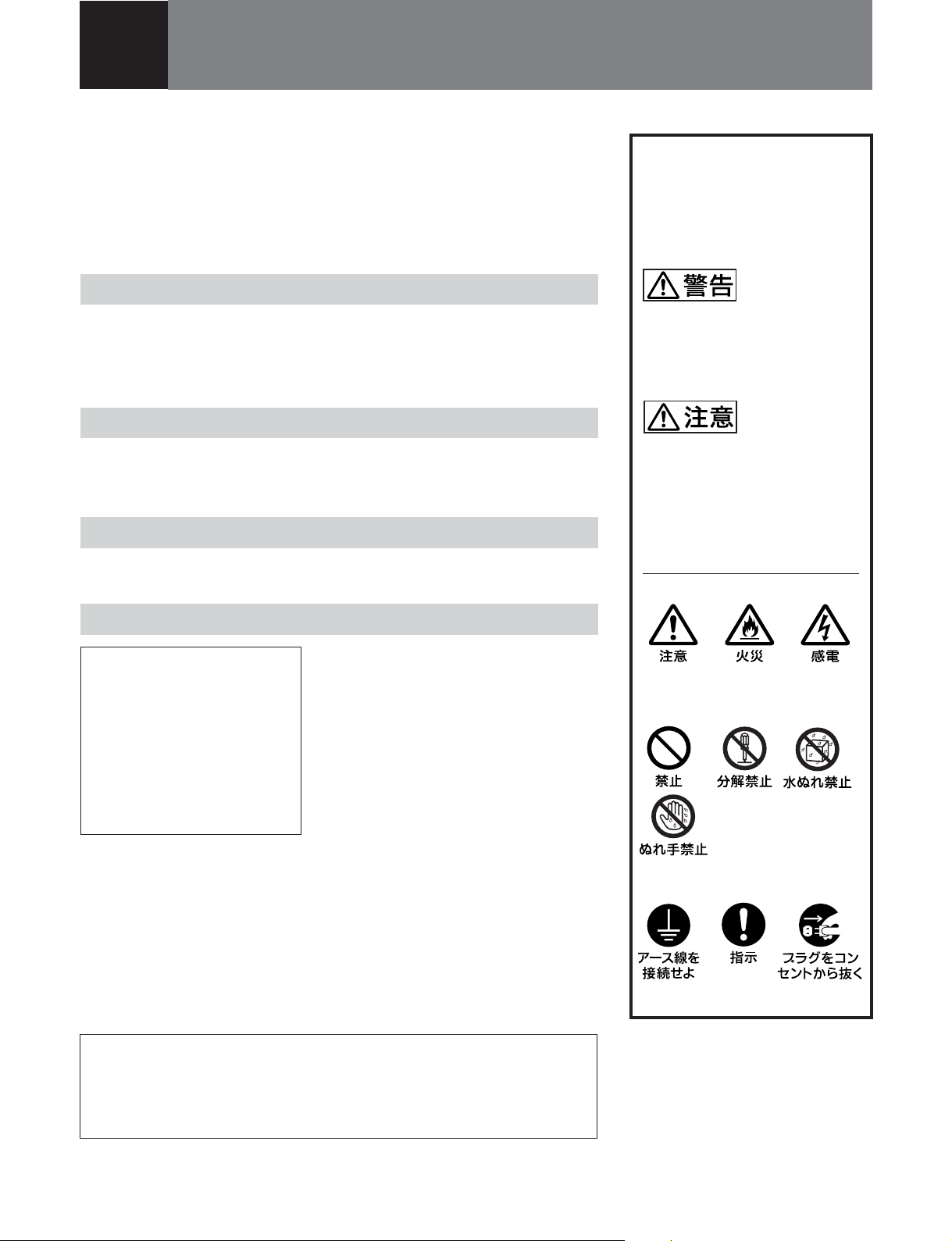
警告表示の意味
取扱説明書および製品では、次
のような表示をしています。表
示の内容をよく理解してから本
文をお読みください。
この表示の注意事項を守らない
と、火災や感電などにより死亡
や大けがなど人身事故につなが
ることがあります。
この表示の注意事項を守らない
と、感電やその他の事故により
けがをしたり周辺の物品に損害
を与えたりすることがありま
す。
注意を促す記号
万一、異常が起きたら
・煙が出たら
・異常な音、においがし
たら
・内部に水、異物が入っ
たら
・モニターを落としたり、
キャビネットを破損し
たときは
この装置は、情報処理装置等電波障害自主規制協議会(VCCI)の基準に基
づく クラスA情報技術装置です。この装置を家庭環境で使用すると電波妨害
を引き起こすこ とがあ り ます。この場合には使用者が適切な対策を講ずるよう
要求されるこ とがあ ります。
1 電源を切る。
2 電源コードや接続コードを抜く 。
,
3 お買い上 げ店ま たはソニーの サー
ビス窓口に連絡する。
行為を禁止する記号
行為を指示する記号
Page 3
目次
.........................................................................................................
.........................................................................................................
使用上のご注意 ...............................................................................................
主な特長..........................................................................................................
各部の名称と働き ...........................................................................................
前面 ....................................................................................................... 8(JP)
裏面 ..................................................................................................... 10(JP)
電源について................................................................................................
お手入れ.......................................................................................................
保証書とアフターサービス ..........................................................................
主な仕様.......................................................................................................
2 (JP)
3 (JP)
6 (JP)
7 (JP)
8 (JP)
12 (JP)
13 (JP)
13 (JP)
14 (JP)
日
本
語
1 (JP)
Page 4
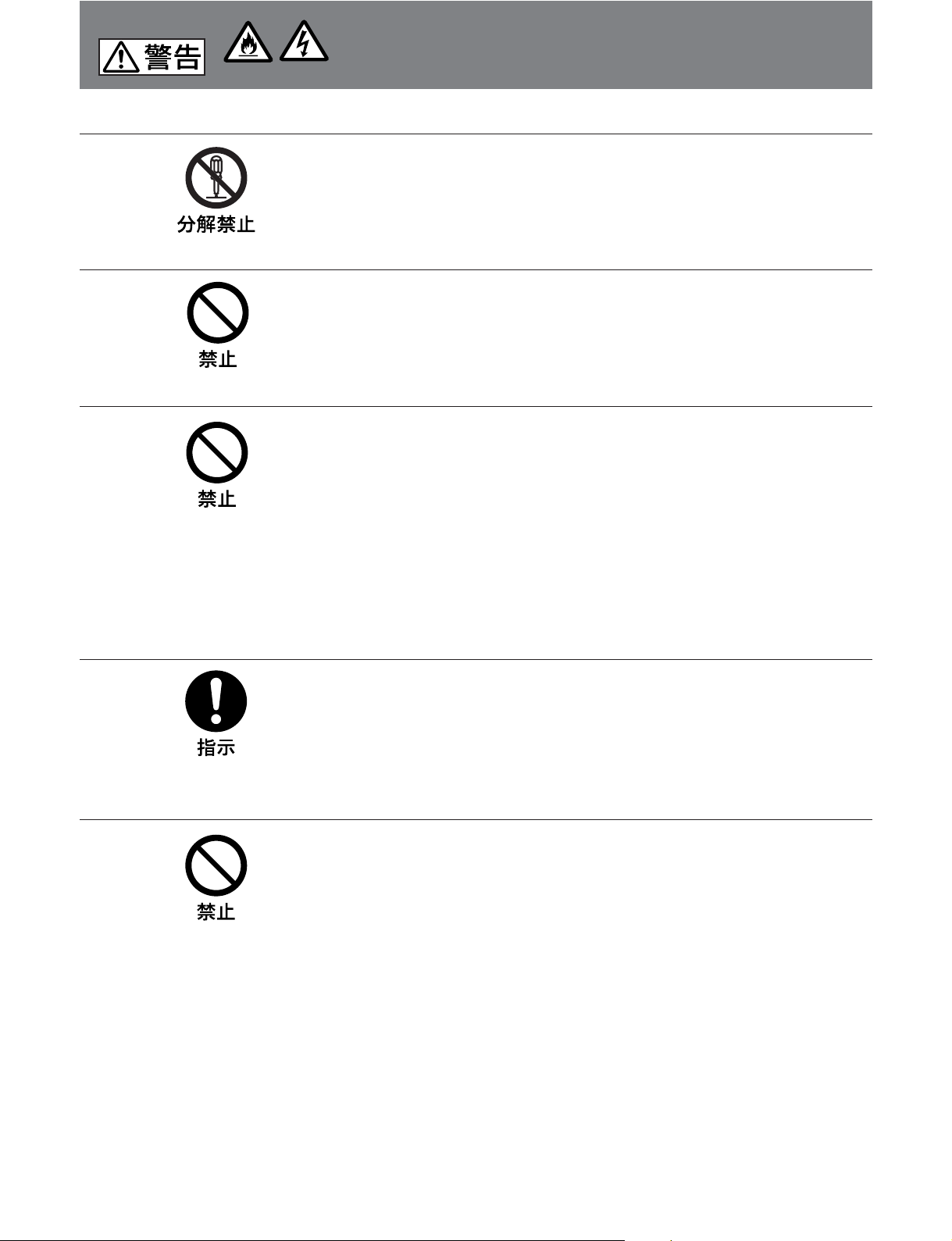
下記の注意を守らないと、火災や感電により
火災 感電
死亡や大けがにつながることがあります。
キャビネットをはずさない、改造しない
内部には電圧の高い部分があり、キャ ビネットや裏ぶたなどをはずしたり、改造し
たりする と、火災や感電の原因となります。内部の調整や設定、点検、修理は、
お買い上げ店またはソニーのサービス窓口にご依頼ください。
内部に水や異物を入れない
水や異物が入ると火災や感電の原因となります。
万一、水や異物が入ったときは、すぐに電源を切り、電源コードや接続ケーブル
を抜いて、お買い上げ店 またはソニーの サービス窓口にご相談ください。
電源コードを傷つけない
電源コードを傷 つけると、火災や感電の原因となります。
• 設置時に、製品と壁やラック、棚などの間に、はさみ込ま ない。
• 電源コードを加 工したり、傷つけたり しない。
• 重いものをのせたり、引 っ張っ たりしない。
• 熱器具に近づけたり、加熱したりしない。
• 電源コードを抜く ときは、必 ずプラグを持って抜く。
万一、電源コードが傷んだら 、お買い上げ店またはソニーのサービス窓口に交換
をご依頼ください。
規定の電源電圧で使う
取扱説明書に記されている電源電圧でお使いください。
DC(直流)電源で動作できるモニターは、取扱説明書に記されている電源アダ
プター あるいはバッ テ リ ーパッ クでお使いく ださい。
規定外の電源電圧での使用は、火災や感電の原因となります。
油煙、湯気、湿気、ほこりの多い場所では設置・使用しない
上記のような場所に設置すると、火災や感電の原因となります。
取扱説明書に記されてい る仕様条件以外の環境での使用は 、火災や感電の原因
となり ます。
2
(JP)
Page 5
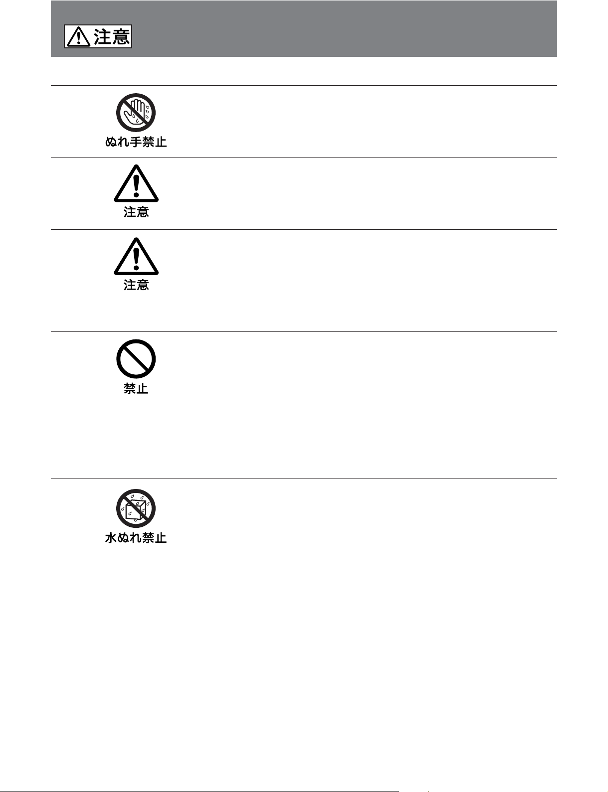
下記の注意を守らないと、
けがをしたり周辺の物品に損害を与えることがあります。
ぬれた手で電源プラグをさわらない
ぬれた手で電源プラグを抜き差しすると、感電の原因となることがあります。
接続の際は電源を切る
電源コードや接続ケーブルを接続するときは、電源を切ってください。感電や故障
の原因となること があります 。
指定された電源コード、接続ケーブルを使う
付属の、あるいは取扱説明書に記されている電源コード、接続ケーブルを使わな
いと、感電 や故障 の原因となるこ とがあり ます。
他の電源コードや接続ケーブルを使用する場合は、お買い上げ店またはソニー の
サー ビス 窓口にご相談ください。
通風孔をふさがない
通風孔をふさぐと内部に熱がこもり、火災や故障の原因となることがあります。風
通しをよくするために次の事項をお守りください。
• 壁から10cm以上離して設置する。
• 密閉された狭い場所に押し込めない。
• 毛足の長い敷物(じゅうたんや布団など)の上に設置しない。
• 布などで包まない。
• あお向けや横倒し、逆さまにしない。
水のある場所に設置しない
水が入っ たり、ぬれた りすると、火災や感電の原因となることがあります。
雨天や降雪中、海岸や水辺での使用は特にご注意ください。
3
(JP)
Page 6
下記の注意を守らないと、
けがをしたり周辺の物品に損害を与えることがあります。
不安定な場所に設置しない
ぐらついた台 の上や傾いたところなどに設置すると、モニターが落ちたり、倒れた
りして、けがの原因となることがあります。
また、設置・取り付け場所の強度を充分にお確かめください。
直射日光の当たる場所や熱器具の近くに設置・保管しない
内部の温度が上がり、火災や故障の原因となることがあります。
真夏の、窓を閉め切った自動車内では50℃を越えることがありますので、ご注意
ください。
転倒、移動防止の処置をする
モニ ター をラック に取り付け・取りはずしすると きは、転 倒・移 動 防止の処置をし
ない と、倒れたり、動いたりして、けがの原因となることがあります。安定した姿勢
で注意深く作業してください。
また、ラ ッ クの設置状況、強度を充分にお確かめください。
モニターの上に乗らない、重い物を載せない
倒れたり、落ちたり、壊れたりして、けがの原因となることがあります。
お手入れの際は、電源を切って電源プラグを抜く
電源を接続したままお手入れをする と、 感電の原因となるこ と があ り ま す。
4
(JP)
Page 7
下記の注意を守らないと、
けがをしたり周辺の物品に損害を与えることがあります。
移動させるときは電源コード、接続ケーブルを抜く
接続したまま移動させる と、電源コー ドや接続ケーブルが傷つき、火災や感電の
原因となることがあります 。
定期的に内部の掃除を依頼する
長い間掃除をしないと内部にホ コリがたまり、 火災や感電の原因となることがあり
ます。1年に1度は、内部の掃除をお買い上げ店ま たはソニーのサービス窓口に
ご依頼ください(有料)。
特に、 湿気の多 くなる梅雨の前に掃除を すると 、より効果的です。
5
(JP)
Page 8

使用上のご注意
モニターの性能を保持するために
磁気に対するご注意
• 磁石、スピーカー、 電気時計、磁石を使用した機器やおもちゃ、
磁気応用健康器具など、磁気を発生するものを近づけないでく
ださい。磁気 の影響を受けて、画面が揺れたり、色が乱れたり
することがあります 。
• モニターの設置の向きによっては、地磁気の影響を受けて、画
面が傾いたり、色が乱れることがありますが、故障ではありませ
ん。このと き は、一度、電源を切って (消磁して)からモニター
の向 きを変えてください。
ブラウン管について
• ブラ ウ ン管の表面はホコリが付きやすいので、ときどき柔らかい
布でふいてください。また、表面は傷つきやすいので、硬い もの
でこすったり 、 たたいた り、ものをぶつけたりしないでください。
• ブラ ウン管の表面に手を触れると弱い電気を感じる ことがあり ま
すが、これはブラ ウン管表面に静電気を帯びているためで、人
体に影響はありません。
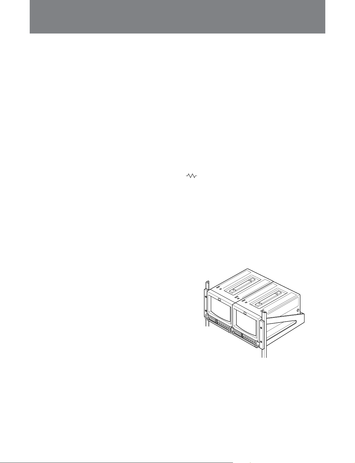
ラックに収納する場合のご注意
モニ ターをラックに収納した場合、他の機器の発熱や通気量の減
少によりモニ ターの周囲温度が上昇し、故障の原因となる場合が
あります。 したがって、モニターを収納する場合には、通気孔の確
保や通気ファンの設置などにより、周囲温度を定められた動作温
度範囲内に適合させるための配慮が必要です。
(動作温度範囲:0〜+35゜C)
クリーニングについて
• お手入れの際は、必ず電源を切って電源プラグを抜いてくださ
い。
• キャビネットの汚 れがひどいときは、水で5〜6倍に薄めた中性
洗剤液に柔らかい布をひたし、かたくしぼっ て から汚れ を ふきと
ります 。このあ と乾いた布でか らぶきをしてください。
• シンナーやベンジンなどの薬品類は、 表面の仕上げをいためた
り、表示が消えてしまうことがあります の で 、使用しないでくださ
い。
6
(JP)
Page 9
主な特長
コンポーネント
デジタルベータカムVTRなどのSMPTE259M/CCIR656-III4:2:2
シリアルデジタル信号を入出力できます。
カラー方式
4
NTSC、PAL、SECAM、NTSC
切り換えは自 動です。入力信号に合った方式で画像を再現します。
HR(High Resolution
蛍光面ピッチ0.25mmのHRトリニトロン管の採用により、中心部の
解像度が450本以上の鮮明な画像が得られます。
ビームカレントフィードバック回路
この回路の採用によ り 、長期間安定したホワイトバランスが 得られ
ます。
くし形フィルター
くし形フィルターの採用により、NTSC信号のクロスカラー妨害(文
字のまわりの虹)やカ ラーノイ ズ(色のにじみ)をなくし、きめ細か
で透明度の高い、しっ とりとし た 画 像が得られま す。
多彩な入力信号に対応
コンポジッ トビデオ信号、Y/C信号に加えて,アナログRGB信号ま
たはコ ンポーネント(Y/R-Y/B-Y)信号を入力することができます。
SDI1)
入出力
2)
4.43
の4つのカラー方式に対応でき、
)トリニトロン
® 3
)
管
モード
16:9
16:9ボタンを押すと画面の垂直方向が圧縮され、16:9の入力信
号を正しい縦横比でモニターすることができます。
アンダースキャンモード
通常画面の外に走査さ れ て いる信号ま で画面に表示し、画像全体
をモニタ ー するこ と ができます。
自動/手動消磁機能
電源を入れると自動的にブラウン管が消磁されます。また、
DEGAUSSボタンを押すことによって手動でスクリーンの消 磁をす
ることが できます。
型入力端子の自動終端
BNC
マークの付いているコネクターのみ)
(
裏面のBNC型入力端子は、出力端子に何もつないでいないとき
は、内部で75Ωに終端されています。出力端子にケーブルをつな
ぐと、内部の75Ωが自動的に解放され、入力端子に入った信号が
そのまま出力さ れま す(ループスルー)。
スタンダードの19インチのラックに収納可能
EIA
マウ ンティングブラケ ットMB-520(別売り)を使うと、 EIA19インチ
ラックにマウン トすることが できます。マウ ント方 法についてはマウン
ティ ングブラケ ットの取扱説明書をご覧ください。
外部同期信号入力端子
外部信号発生器などからの同期信号を入力できます。EXTSYNC
ボタ ンを押すと、外部同期で動作します。
ブルーオンリーモード
ブルーオンリーモードにする と、RGBのカソードがすべて青の信号
で動作し、これが白黒画像として表示されます。色の濃さ(ク ロマ)
や色相(フェーズ)の調整、VTRノイズの監視に便利です。
..............................................................................................................................................................................................................................................................
1) SDI:SerialDigitalInterface
2) NTSC4.43は、PAL、SECAM地域でNTSCテープの再生ができるように設計されたVTRの再生信号です。
3) トリニトロンはソニー株式会社の登録商標です。
7 (JP)
Page 10
各部の名称と働き
前面
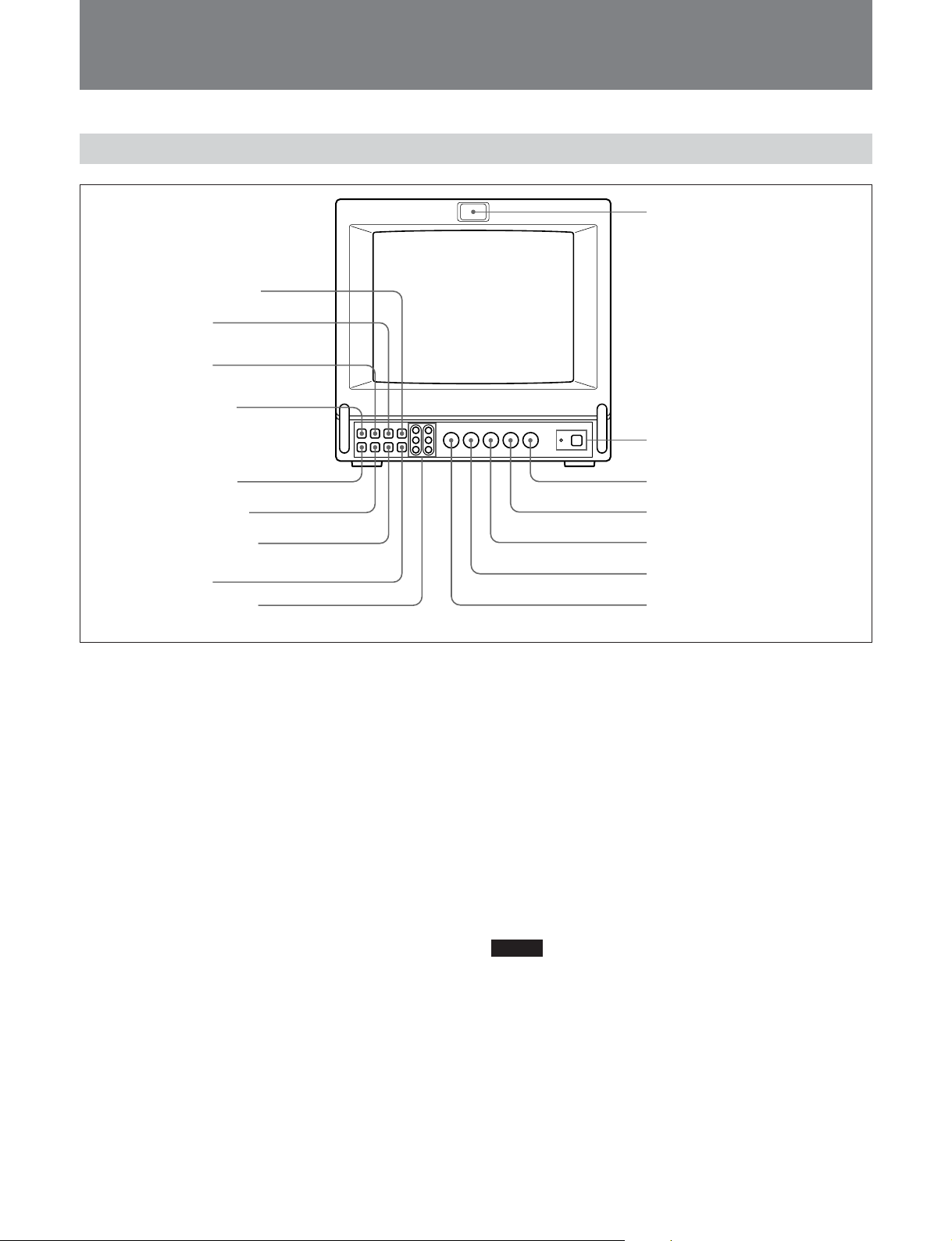
1
タリーランプ
8
DEGAUSS
9
SYNC INT/EXT
(内部/外部同期)ボタン
0
LINE/RGB
切り換えボタン
qa
A/B、SDI/RGB
切り換えボタン
qs
BLUE ONLY
qd
UNDER SCAN
qf
H/V DELAY
ディレイ)ボタン
qg
16:9
qh
R/G/B BIAS、GAIN
整孔
1
タリーランプ
(消磁)ボタン
入力
入力
ボタン
ボタン
(水平/垂直
ボタン
調
このラ ンプは点灯させることができます。タリー制御の配線が必要
です。
◆
REMOTE端子のピン配列については15(JP)ページをご覧ください。
2
POWER
(電源)スイッチとインジケーター
スイ ッチを押し込むと電源が入り、 イ ンジケーター (緑 ) が点灯し
ます。
もう一度押すと、電源が切れます。
インジケーターは外部 電源の電圧イ ンジケーターも兼 用していま す。
DC12VINジャックに つない だ 電 源 の 電 圧 が下がったときにはイン
ジケーターが 点滅します。
3
CONTR
調整つまみ
右へ回すとコントラス トが強くなります。
左へ回すとコントラス トが弱くなります。
4
PHASE
(色相)調整つまみ
このつまみは、NTSCのカラー方式の信号にだけ働きます。
右へ回すと、肌色が緑がかります。
左へ回すと、肌色が紫がかります。
5
CHROMA
2
POWER
インジケーター
3
CONTR
4
PHASE
5
CHROMA
6
BRIGHT
7
APER
(色の濃さ)調整つまみ
(電源)スイッチと
調整つまみ
(色相)調整つまみ
(色の濃さ)調整つまみ
(明るさ)調整つまみ
(アパーチャー)調整つまみ
右へ回すと、色が濃くなります。
左へ回すと、色が薄くなります。
6
BRIGHT
(明るさ)調整つまみ
右へ回すと、画面が明るくなります。
左へ回すと、画面が暗くなります。
7
(アパーチャー)調整つまみ
APER
右へ回すと、くっきりとした 画 像 に なります。
左へ回すと、やわらかな画像になります。
ご注意
• PHASE調整つまみは、PALカラー方式の信号の映像、SECAM
カラー方式の信号の映像、アナログRGB信号の映像、アナロ グ
コンポーネント信 号の映像、およびデジタ ルコンポーネ ント信 号 の
映像には働きません。。
• CHROMA調整つまみとAPER調整つまみは、アナログRGB信
号の映像には働きません。
8
(JP)
Page 11

8
DEGAUSS
消磁したいとき、このボタン を1 回押します。
ご注意
DEGAUSSボタンを短い間隔で連続して動作させると、色ムラを起
こすこ とがあ り ます。
9
SYNC INT/EXT
通常は押さないでおきます。このとき 、 画面に出ているコ ンポジッ
トビデオ信号に含まれている同期信号で動作します。
(INT:内部同期モード)
裏面のEXTSYNC入力端子から 入力された外部同期信号で同期
をとる場合は、このボタ ンを押し込みます。(EXT:外部同期モード)
デジタ ルコ ンポーネ ント信号のときは、常に内部同期モードで動作
します。
(消磁)ボタン
(内部/外部同期)ボタン
qd
UNDER SCAN
押し込むとアンダースキャンモー ドになり ます。画面サイズが約3%
縮小され、画像の四隅までが画面に表示されます。
qf
H/V DELAY
水平・垂直同期信号を同時にモニターしたいときに押し込みます。
水平同期信号は画面の左から約1/4のところに現れます。垂直同
期信号は画面のほぼ中央に現れます。
16:9
ボタン
qg
押すと、画面の垂直方向が圧縮され、16:9の入力信号を正しい
縦横比でモニターでき ます。
16:9モード時にUNDERSCANボタンqdを押せば、16:9の画像
の四隅までが画面に表示されます。
ボタン
(水平/垂直ディレイ)ボタン
0
LINE/RGB
モニ ターしたい入力信号を選びます。COMPONENTSDI端子、
または RGB/COMPONENT端子からの信号で動作するとき押し
ます (RGB)。LINEA端子またはLINEB端子からの信号をモニ
ターする ときはこのボタンを押 さないでおきます(LINE)。
qa
A/B、SDI/RGB
LINE/RGB
裏面のLINEA端子からの信号をモニターするときは、押さないで
おき ます(A)。押し込む とLINEB端子からの信号をモニターでき
ます (B)。
LINE/RGB
裏面のRGB入力端子からの信号の種類を選びます。
デジタル信号をモニタ ーする ときは、押さないでおきます (SDI)。
アナロ グRGB信号、またはコ ンポーネ ント信号で動作するときは押
します (RGB)。このとき、後面パネルのRGB/YR-YB-Y切り換え
スイ ッチを切り換えることにより、信 号 の 選択ができます。
qs
BLUE ONLY
押し込むと赤と緑の信号がカットされ、青信号のみが白黒画像とし
て表示 されます。 色の濃さ(ク ロマ) や色相(フェーズ)の調整、
VTRノイズの監視が容易に行えます。
入力切り換えボタン
入力切り換えボタン
入力切り換えボタンが
入力切り換えボタンが
ボタン
になっているとき
LINE
になっているとき
RGB
qh
R/G/B BIAS、GAIN
ホワイトバランス調整に使います。 R(赤)、G(緑)、B(青)用にそ
れぞれBIAS調整孔とGAIN調整孔があります。
:暗部の色温度を微調整します。
BIAS
:明部の色温度を微調整します。
GAIN
これらの微調整には2mm径のドライバーなどが必要です。
調整孔
ご注意
色相(フェーズ ) の調整は、NTSC以外の信号には行なうことが で
きません 。
9 (JP)
Page 12
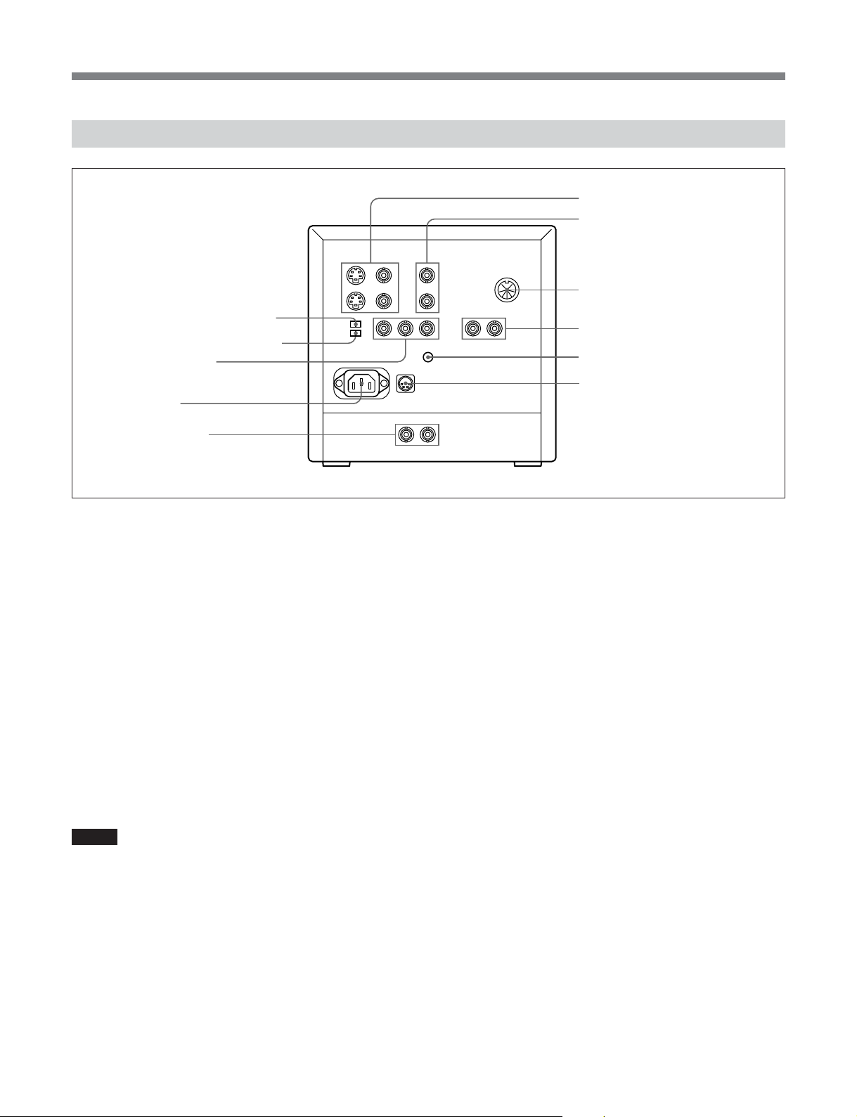
各部の名称と働き
裏面
wd
COMPONENT LEVEL
wf
RGB/Y R-Y B-Y
wg
RGB/COMPONENT
入力端子(
wh
wj
qj
LINE A
この端子からの信号をモニターするときは、前面のLINE/RGB入
力切り換えボタンは押さず(LINE),A/B、SDI/RGB入力切り換え
ボタ ン も押さ ないでおきます (A)。
Y/C IN
ソケット
AC IN
COMPONENT SDI
入出力端子(
(画像入力)端子(4ピンミニDIN)
VTRやビデオカメラなど外部の 機器のY/C出力に接続します。
Y/C OUT
Y/CIN端子に接続したY/C信号のループスルー出力。VTR
などの外部の機器のY/C入力に接続します。
VIDEO IN
VTRやカラービデオカメラの映像出力と接続します。
VIDEO OUT
VIDEOIN端子に接続した映像信号のループスルー出力。
VTRや他のモニターの映像入力と接続します。
ご注意
Y/CIN端子にプラグが接続されているときは、VIDEOIN端子へ
の接続は自動的に切れます。
qk
LINE B
この端子からの信号をモニターするときは、前面のLINE/RGBボ
タンは 押さない状態にし(LINE)、A/B、SDI/RGB入力切り換えボ
タンは 押して ください(B)。
型)
BNC
BNC
入出力端子
(映像出力)端子(4ピンミニDIN)
(映像入力)端子(BNC型)
(映像出力)端子(BNC型)
入出力端子
スイッチ
切り換えスイッチ
型)
qj
LINE A
qk
LINE B
ql
REMOTE
w;
EXT SYNC
入出力端子(
wa
V HOLD
ws
DC 12V IN
(
VIDEO IN
VIDEO OUT
ql
REMOTE
外部の機器を接続することにより、タリーランプの点灯/消灯、入
力の切り換えなどをコントロールする ことができます。
◆
REMOTE端子のピン配列については15(JP)ページをご覧ください。
w;
EXT SYNC
この端子 を使う場合は前面のSYNCINT/EXTボタンを押しておき
ます (EXT)。
(入力):本機を外部同期で動作させるとき、外部同期信号
IN
OUT
(映像入力)端子(BNC型)
VTRやカラービデオカメラの映像出力と接続します。
(映像出力)端子(BNC型)
VIDEOIN端子に接続した映像信号のループスルー出力。
VTRや他のモニターの映像入力と接続します。
端子(8ピンミニ
(外部同期)入出力端子(
発生器などからの基準信号を入力します。
(出力):IN端子に接続した同期信号のループスルー出
力。 本機と同期して動作させる他のビデオ機器の外部同期
入力端子と接続します。
入出力端子
入出力端子
端子(8ピンミニ
(外部同期)
BNC
(垂直同期)調整つまみ
ジャック
DIN
ピン)
)
XLR型、4
型)
BNC
型)
DIN
)
10
(JP)
Page 13
wa
V HOLD
(垂直同期)調整つまみ
画面が上下に分かれたり、流れたりするときに調整します。つまみ
を回 し 、画像の流れが止まったら、他の受像信号に切り換えて、い
ずれの信号でも安定するように合わせます。
ws
DC 12V IN
ジャック(
XLR型、4
ピン)
外部電源DC12Vを接続することにより、本器を動作させることが
でき ます。
wd
COMPONENT LEVEL
スイッチ
コンポーネン ト入力時の信号レベルにより、SMPTEまたは、BETA
に切り換えます。 日本国内では主にBETAが用いられています。
N10/SMPTE
BETA 0
wf
RGB/Y R-Y B-Y
アナログRGB信号を入力するときこの位置にします。
RGB:
Y R-Y B-Y:
:100/0/100/0のコンポーネント信号のとき
: 100/0/75/0のコンポーネント信号のとき
切り換えスイッチ
コンポーネント信号を入 力 するとき、この位置にし
ます。
wg
RGB/COMPONENT
入力端子(
BNC
型)
この端子からの信号をモニターするときは、前面のLINE/RGB入
力切り換えボタンを押し(RGB)、A/B、SDI/RGB入力切り換えボ
タンも押します(RGB)。
この場合、前面の SYNCINT/EXT ボタンが押されて いない
(INT)ときには、G/Yチャンネルに含まれている同期信号で動作
します。
• アナログ
信号で動作するとき
RGB
ビデオカメラなどのアナ ログRGB出力につなぎます。
前面のA/B、SDI/RGB切り換えスイッチを押します (RGB)。
背面のRGB/YR-YB-Y切り換えスイッチ wfをRGB側にします。
• コンポーネント信号で動作するとき
ソニーのベータカムVTRなどのY/R-Y/B-Yコンポーネント出 力に
つな ぎま す。
前面のA/B、SDI/RGB切り換えスイッチを押します(YR-YB-Y)。
背面のRGB/YR-YB-Y切り換えスイッチ wfをYR-YB-Y側にし
ます。
wh
AC IN
ソケット
付属の電源コードをつなぎます。
wj
COMPONENT SDI
入出力端子(
BNC
型)
前面パネルのLINE/RGB入力切り換えボタンを押し(RGB)、A/
BSDI/RGB入力切り換えボタンを押さない状態にしておきます
(SDI)。
デジタルベータカムVTRなどからのSMPTE259M/CCIR656-
IN:
III4:2:2シリアルデジタル信号を入力します。
COMPONENTSDI入力端子に接続したデジタル信号を
OUT:
出力します。(ア ク ティブスルー)。
この端子には、下記のケーブルを接続することをおすすめしま す。
同軸ケーブル:5C-2V(最大200m)
藤倉電線(株)製または相当品
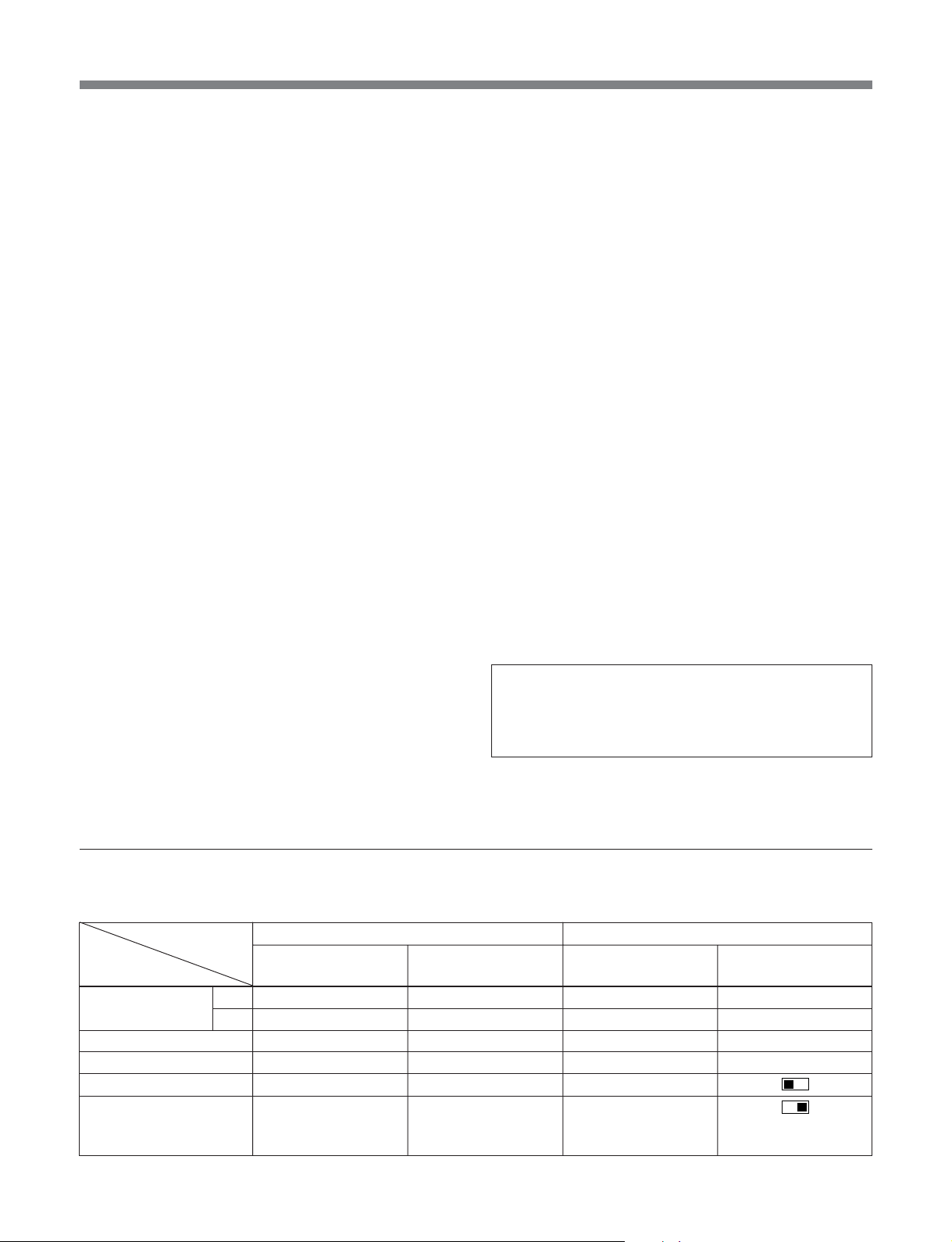
前面パネル、後面パネルのボタン、端子、スイッチと入力信号の関係
前面パネル、後面パネルのボタン、端子、スイッチと入力信号の関係は下の表のとおりです。
ボタン、端子、
スイッチ
入力信号
COMPOSITE A
Y/C
COMPONENTSDI
ANALOGRGB
COMPONENT
(YR-YB-Y)
A/B、SDI/RGB
入力切り換えボタン qa
A 4
B
B $
A 4
SDI 4
RGB $
RGB $
前面パネル
LINE/RGB
入力切り換えボタン 0
LINE 4
LINE 4
LINE 4
RGB $
RGB $
RGB $
入力端子
LINEA(VIDEO)
LINEB
LINEA (Y/C)
COMPONENTSDI
RGB/COMPONENT
RGB/COMPONENT
後面パネル
RGB/YR-YB-Y
切り換えスイ ッチ wf
−
−
−
−
RGB
Y
R-Y
B-Y
11 (JP)
Page 14
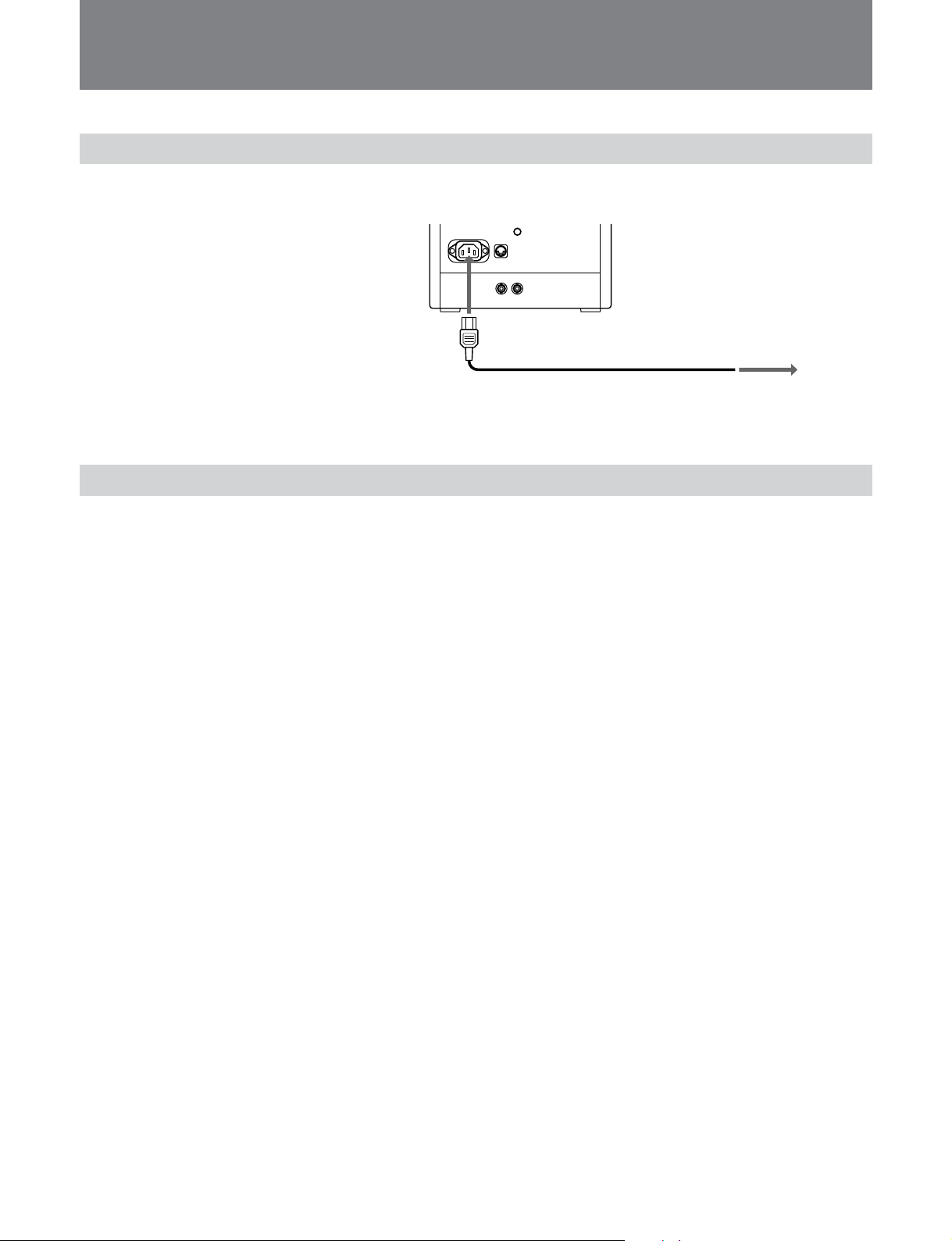
電源について
屋内で使うには
付属の電源コードを裏 面のACINソケットに 差し 込 み 、 壁の電源につないでご利用ください。
へ
AC IN
壁の電源へ
電源コードが ACINソケットに つなが れ て いるときは 、DC12VINジャックにつながれてい
る電源との接続は自動的に切れます。
DC 12V IN
ジャックを使うには
本機DC12VINジャックに12Vの直流電源を接続することができます。
12
(JP)
Page 15

お手入れ
保証書とアフターサービス
キャビネットや表面のガラスは柔らかい布でおふきください。キャビ
ネッ トの汚れがひどいときは、水で5〜6倍に薄めた中性洗剤液に
柔らかい布をひたし、かた くしぼってから汚れをふきとります。この
あと乾 いた布 でか らぶきしてください。
シンナーや ベンジンなどの薬品類は、表面の仕上げをいためた り、
表示が消えてしまうことがあります ので、 使用しないでください。な
お、 お手入れのときは、必ず電源を切ってください。
ホコリは大敵
内部にホコリがたまると、故障や事故の原因になることがあります 。
いつも好調にお使いいた だくため、年に一度くらいは内部の掃除 ・
点検をお買い上げ店または担当セールスマンにご相談ください。
保証書
•この製品には保証書が添付されていますので、お買い上げの際
お受け取りください。
• 所定事項の記入および記載内容をお確 かめのうえ、大切に保存
してください。
アフターサービス
調子が悪いときはまずチェックを
この説明書をもう一度ご覧になってお調べください。
それでも具合の悪いときはサービスへ
お買い上げ店、または添付の「ソニー業務用製品ご相談窓口のご
案内」にある お近くのソニーサー ビス窓口にご相談ください。
保証期間中の修理は
保証書の記載内容に基づいて修理 させていただきます。詳しく は
保証書をご覧ください。
保証期間経過後の修理は
修理によって機能が維持できる場合は、ご要望により有料修理を
させていただきます。
13 (JP)
Page 16

主な仕様
主な仕様
映像信号系
カラー方式 NTSC、PAL、SECAM、NTSC4.43
解像度 450TV本
アパーチャー補正量 −4.0dB〜+6.0dB(3.0MHzにて)
周波数特性 6.0MHz(−3.0dB)
同期 AFC時定数1.0ms
画像系
ノーマルスキャン CRT有効画面の6%オーバースキャン
アンダースキャン CRT有効画面の3%アンダースキャン
直線性 画面高の2.0%以内
コンバージェ ンス 中心部0.4mm(標準)
周辺部0.5mm(標準)
ラスターサイ ズ安定度
H1.0%、V1.5%
高電圧変動率 3.0%
色温度 D93
入力
COMPONENTSDIIN:BNC型
シリアルデジタル (270Mbit/秒)
SMPTE259M/CCIR656-III
Y/CIN:4ピンミニDIN
ピン配列については15(JP)ページをご
◆
覧く ださい。
VIDEOIN:BNC型 1Vp-p、±6dB、同期負
R/R-Y、G/Y、B/B-Y:BNC型
R、G、Bチャンネル:0.7Vp-p、±6dB
Gチャンネルに負の同期信号がある場
合は、 内部同期モードで動作する。
同期信号:0.3Vp-p
R-Y、Y、B-Yチャンネル:0.7Vp-p、±6dB
(100%クロミナンスの標準カラ ーバー信号の
とき)
EXTSYNCIN:BNC型
複合同期4Vp-p、±6dB、同期負
ループスルー出力
COMPONENTSDIOUT:BNC型
アクテ ィ ブス ルー 出力
シリアルデジタル (270Mbit/秒)
SMPTE259M/CCIR656-III
Y/COUT:4ピンミニDIN(75Ω自動終端)
VIDEOOUT:BNC型(75Ω自動終端)
EXTSYNCOUT:BNC型(75Ω自動終端)
REMOTE
REMOTE:8ピンミニDIN
入力
ピン配列については15(JP)ページをご
◆
覧く ださい。
その他
消費電力 48WAC
44WDC
電源 100VAC、50/60Hz
12VDC
動作条件
温度 0〜+35℃
湿度 0〜90%(結露のないこと)
気圧 700〜1060hPa
輸送・保管条件
温度 −10〜+40℃
湿度 0〜90%
気圧 700〜1060hPa
最大外形寸法 約217×217×352.5mm
(幅/高さ/奥行き)(最大突起部を含まず)
重量 約8.5kg
付属品 電源コード(1)
8ピンプラグ付コード(1)
オペ レーションマニュアル(1)
タリープレート(1)
保証書(1)
ACプラグホルダー(1)
「ソニー業務用製品ご相談窓口のご案内」(1)
14 (JP)
Page 17
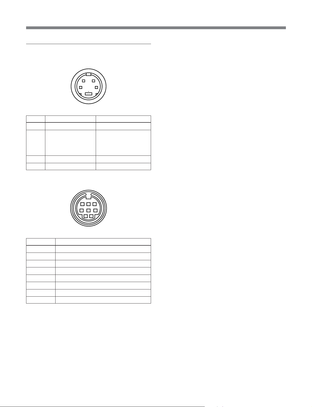
ピン配列
Y/C IN
REMOTE
入力端子(4ピン ミ ニ
ピン
No.
1Y入力 1Vp-p、同期負、75Ω
2 CHROMA 286mVp-p(NTSC)
サブキャリア入力 300mVp-p(PAL)、バース ト
3 GND(Y入力用) アース
4 GND(CHROMA入力用) アース
信号 信号レベル
端子(8ピン ミ ニ
)
DIN
12
43
Y-C間遅延時間0±100nsec、
75Ω
)
DIN
678
3
45
12
ピン
No.
14:3/16:9
2 H/Vディレイ
3アース
4内部/外部同期
5タリー
6アンダースキャン/ノーマルスキャ ン
7 A/BまたはRGB/YR-YB-Y
8 LINE/RGB
信号
リモートコントロールする場合は、希望の機能を持つピンを各々ピ ン
3(アース) につないでく ださい。
本機の仕様および外観は、改良のため予告なく変更することがあ
ります が 、ご了承ください。
15 (JP)
Page 18
English
WARNING
To prevent fire or shock hazard, do not
expose the unit to rain or moisture.
To avoid electrical chock, do not open the
cabinet. Refer servicing to qualified
personnel only.
This symbol is intended to alert the user to
the presence of uninsulated “dangerous
voltage” within the product’s enclosure that
may be of sufficient magnitude to constitute
a risk of electric shock to persons.
This symbol is intended to alert the user to
the presence of important operating and
maintenance (servicing) instructions in the
literature accompanying the appliance.
Important Safety Instruction
1) Read these instructions.
2) Keep these instructions.
3) Heed all warnings.
4) Follow all instructions.
5) Do not use this apparatus near water.
6) Clean only with dry cloth.
7) Do not block any ventilation openings. Install in
accordance with the manufacturer’s instructions.
8) Do not install near any heat sources such as radiators,
heat registers, stoves, or other apparatus (including
amplifiers) that produce heat.
9) Do not defeat the safety purpose of the polarized or
grounding-type plug. A polarized plug has two blades
with one wider than the other. A grounding type plug has
two blades and a third grounding prong. The wide blade
or the third prong are provided for your safety . If the
provided plug does not fit into your outlet, consult an
electrician for replacement of the obsolete outlet.
10)Protect the power cord from being walked on or pinched
particularly at plugs, convenience receptacles, and the
point where they exit from the apparatus.
11)Only use attachments/accessories specified by the
manufacturer.
12)Use only with the cart, stand, tripod, bracket, or table
specified by the manufacturer, or sold with the apparatus.
When a cart is used, use caution when moving the cart/
apparatus combination to avoid injury from tip-over.
13)Unplug this apparatus during lightning storms or when
unused for long periods of time.
14)Refer all servicing to qualified service personnel.
Servicing is required when the apparatus has been
damaged in any way , such as power-supply cord or plug
is damaged, liquid has been spilled or objects have fallen
into the apparatus, the apparatus has been exposed to
rain or moisture, does not operate normally, or has been
dropped.
AVERTISSEMENT
Afin d’éviter tout risque d’incendie ou d’électrocution, ne pas
exposer cet appareil à la pluie ou à l’humidité.
Afin d’écarter tout risque d’électrocution, garder le coffret
fermé. Ne confier l’entretien de l’appareil qu’à un personnel
qualifié.
Consignes de sécurité importantes
1) Lisez les directives suivantes.
2) Conservez ces directives.
3) Observez et respectez tous les avertissements.
4) Suivez toutes les directives.
5) N’utilisez pas cet appareil près de l’eau.
6) Nettoyez cet appareil uniquement avec un chiffon sec.
7) Ne bouchez pas les fentes de ventilation. Respectez les
directives du fabricant pour l’installation de l’appareil.
8) N’installez pas l’appareil à proximité d’une source de
chaleur telle qu’un radiateur, une bouche d’air chaud, une
cuisinière ou tout autre appareil (y compris des
amplificateurs) émettant de la chaleur.
9) Ne désactivez pas le dispositif de sécurité appliqué à la
fiche polarisée ou à la fiche avec mise à la terre. Une
fiche polarisée est équipée de deux lames dont l’une est
plus large que l’autre. Une fiche avec mise à la terre est
2
Page 19
équipée de deux lames et une broche destinée à la mise
à la terre. Sur ces types de fiches, la lame la plus large et
la troisième broche sont des dispositifs de sécurité. Si
vous ne réussissez pas à brancher la fiche fournie dans
la prise de courant, consultez un électricien et faites
remplacer la prise par une neuve.
10)Ne placez pas le cordon d’alimentation dans des endroits
passants et assurez-vous qu’il ne peut pas être pincé,
surtout au niveau des fiches, de la prise de courant et à
l’endroit où il sort de l’appareil.
11)Utilisez uniquement les éléments de raccordement et les
accessoires recommandés par le fabricant.
12)Utilisez l’appareil uniquement avec le chariot, le socle, le
trépied, le support ou la table recommandés par le
fabricant ou achetés avec l’appareil. Lorsque vous utilisez
un chariot, prenez des précautions en déplaçant le
chariot et l’appareil afin de ne pas les renverser, ce qui
pourrait entraîner des blessures.
13)Débranchez cet appareil en cas d’orage ou lorsque vous
ne l’utilisez pas pendant de longues périodes.
14)Pour toute réparation, adressez-vous à un réparateur
qualifié. Faites réparer l’appareil s’il a été endommagé de
quelque manière que ce soit, par exemple si le cordon
d’alimentation ou sa fiche sont endommagés, si du
liquide ou tout autre corps étranger a pénétré dans
l’appareil, si l’appareil a été exposé à la pluie ou à
l’humidité, s’il ne fonctionne pas normalement ou s’il a
été échappé.
English
ATTENZIONE
Per evitare incendi o cortocircuiti, l’apparecchio non deve
essere esposto alla pioggia o all’umidità.
Per evitare scosse elettriche, non aprite l’apparecchio. Per le
riparazioni rivolgetevi solo a personale qualificato.
CAUTION:
Danger of explosion if battery is incorrectly replaced.
Replace only with the same or equivalent type recommended
by the manufacturer. Discard used batteries according to the
manufacturer’s instructions.
ATTENTION
Il y a un risque d’explosion si la pile est mal insérée.
Remplacer la pile uniquement par une pile de même type ou
de type équivalent recommandé par le fabricant. Jeter les
piles usées conformément aux instructions du fabricant.
VORSICHT:
Es besteht Explosionsgefahr, wenn die Batterie inkorrekt
eingelegt wird.
Es darf nur eine identische oder eine vom Hersteller
empfohlene Batterie des gleichen Typs eingesetzt werden.
Entladene Batterien sind nach den Anweisungen des
Herstellers zu entsorgen.
PRECAUCION
Peligro de explosión en caso de haberse instalado
incorrectamente la betería.
Cambie sólo por una del mismo tipo o especificaciones
equivalentes, de entre las recomendadas por el fabricante.
Las baterías viejas se deben eliminar siguiendo las
instrucciones del fabricante.
WARNUNG
Um Feuergefahr und die Gefahr eines elektrischen Schlages
zu vermeiden, darf das Gerät weder Regen noch
Feuchtigkeit ausgesetzt werden.
Um einen elektrischen Schlag zu vermeiden, darf das
Gehäuse nicht geöffnet werden. Überlassen Sie
Wartungsarbeiten stets nur einem Fachmann.
ADVERTENCIA
Para evitar incendios o el riesgo de electrocución, no
exponga la unidad a la lluvia ni a la humedad.
Para evitar descargas eléctricas, no abra la unidad. En caso
de avería, solicite los servicios de personal cualificado.
ATTENZIONE:
Pericolo di esplosione se la pila viene sostituita
scorrettamente.
Sostituirla solo con un’altra uguale o di un tipo equivalente
consigliato dal fabbricante. Gettare via le pile usate secondo
le istruzioni del fabbricante.
Note
The socket-outlet should be installed near the equipment and
be easily accessible.
Remarque
La prise doit être près de l’appareil et facile d’accès.
Hinweis
Zur Trennung vom Netz ist der Netzstecker aus der
Steckdose zu ziehen, welche sich in der Nähe des Gerätes
befinden muß und leicht zugänglich sein soll.
3
Page 20

Nota
La toma mural debe estar instalada cerca del equipo y debe
accederse a ésta con facilidad.
Nota
La presa di corrente deve essere situata vicino
all’apparecchio e deve essere facilmente accessibile.
WARNING: THIS WARNING IS APPLICABLE FOR USA
ONLY.
If used in USA, use the UL LISTED power cord specified
below.
DO NOT USE ANY OTHER POWER CORD.
For the customers in Europe (BVM-9045D)
This product with the CE marking complies with both the
EMC Directive (89/336/EEC) and the Low Voltage Directive
(73/23/EEC) issued by the Commission of the European
Community.
Compliance with these directives implies conformity to the
following European standards:
• EN60950: Product Safety
• EN55103-1: Electromagnetic Interference (Emission)
• EN55103-2: Electromagnetic Susceptibility (Immunity)
This product is intended for use in the following
Electromagnetic Environment(s):
E1 (residential), E2 (commercial and light industrial), E3
(urban outdoors) and E4 (controlled EMC environment, ex.
TV studio).
Plug Cap Parallel blade with ground pin
(NEMA 5-15P Configuration)
Cord Type SVT, three 16 or 18 AWG wires
Length Less than 2.5 m (8 ft 3 in)
Rating Minimum 10 A, 125 V
Using this unit at a voltage other than 120V may require the
use of a different line cord or attachment plug, or both. To
reduce the risk of fire or electric shock, refer servicing to
qualified service personnel.
For the customers in the USA
This equipment has been tested and found to comply with
the limits for a Class A digital device, pursuant to Part 15 of
the FCC Rules. These limits are designed to provide
reasonable protection against harmful interference when the
equipment is operated in a commercial environment. This
equipment generates, uses, and can radiate radio frequency
energy and, if not installed and used in accordance with the
instruction manual, may cause harmful interference to radio
communications. Operation of this equipment in a residential
area is likely to cause harmful interference in which case the
user will be required to correct the interference at his own
expense.
You are cautioned that any changes or modifications not
expressly approved in this manual could void your authority
to operate this equipment.
The shielded interface cable recommended in this manual
must be used with this equipment in order to comply with the
limits for a digital device pursuant to Subpart B of Part 15 of
FCC Rules.
Pour les clients européens (BVM-9045D)
Ce produit portant la marque CE est conforme à la fois à la
Directive sur la compatibilité électromagnétique (EMC) (89/
336/CEE) et à la Directive sur les basses tensions (73/23/
CEE) émises par la Commission de la Communauté
européenne.
La conformité à ces directives implique la conformité aux
normes européennes suivantes:
• EN60950: Sécurité des produits
• EN55103-1: Interférences électromagnétiques (émission)
• EN55103-2: Sensibilité électromagnétique (immunité)
Ce produit est prévu pour être utilisé dans les
environnements électromagnétiques suivants:
E1 (résidentiel), E2 (commercial et industrie légère), E3
(urbain extérieur) et E4 (environnement EMC contrôlé ex.
studio de télévision).
Für Kunden in Europa (BVM-9045D)
Dieses Produkt besitzt die CE-Kennzeichnung und erfüllt
sowohl die EMV-Direktive (89/336/EEC) als auch die
Direktive Niederspannung (73/23/EEC) der EG-Kommission.
Die Erfüllung dieser Direktiven bedeutet Konformität für die
folgenden Europäischen Normen:
• EN60950: Produktsicherheit
• EN55103-1: Elektromagnetische Interferenz (Emission)
• EN55103-2: Elektromagnetische Empfindlichkeit
(Immunität)
Dieses Produkt ist für den Einsatz unter folgenden
elektromagnetischen Bedingungen ausgelegt:
E1 (Wohnbereich), E2 (kommerzieller und in beschränktem
Maße industrieller Bereich), E3 (Stadtbereich im Freien) und
E4 (kontrollierter EMV-Bereich, z.B. Fernsehstudio)
4
Page 21

Voor de klanten in Nederland
• Dit apparaat bevat een vast ingebouwde batterij die niet
vervangen hoeft te worden tijdens de levensduur van het
apparaat.
• Raadpleeg uw leverancier indien de batterij toch vervangen
moet worden.
De batterij mag alleen vervangen worden door
vakbekwaam servicepersoneel.
• Gooi de batterij niet weg maar lever deze in als klein
chemisch afval (KCA).
• Lever het apparaat aan het einde van de levensduur in voor
recycling, de batterij zal dan op correcte wijze verwerkt
worden.
Note
Be sure to use the supplied power cord for this monitor, or
this monitor may not conform with the FCC Rules or EEC
Directive 89/336/EEC.
Remarque
Utiliser le cordon d’alimentation fourni pour ce moniteur,
sinon il pourrait ne pas être conforme aux règles FCC ou à la
directive CEE 89/336/EEC.
Hinweis
Dieser Monitor darf ausschließlich mit dem mitgelieferten
Netzkabel betrieben werden, weil anderenfalls der Monitor
nicht mehr die FCC-Vorschriften oder die EG-Richtlinie 89/
336/EWG erfüllt.
ATTENTION – When the product is installed in a rack:
a) Elevated operating ambient temperature
If installed in a closed or multi-unit rack assembly, the
operating ambient temperature of the rack environment
may be greater than room ambient. Therefore,
consideration should be given to installing the equipment
in an environment compatible with the manufacturer’s
maximum rated ambient temperature (Tmra: 0°C to 35°C
(32°F to 95°F )).
b) Reduced air flow
Installation of the equipment in a rack should be such that
the amount of air flow required for safe operation of the
equipment is not compromised.
c) Mechanical loading
Mounting of the equipment in the rack should be such
that a hazardous condition is not achieved due to uneven
mechanical loading.
d) Circuit overloading
Consideration should be given to the connection of the
equipment to the supply circuit and the effect that
overloading of circuits might have on overcurrent
protection and supply wiring.
Appropriate consideration of equipment nameplate
ratings should be used when addressing this concern.
e) Reliable earthing
Reliable earthing of rack-mounted equipment should be
maintained. Particular attention should be given to supply
connections other than direct connections to the branch
circuit (e.g., use of power strips).
For the customers in the UNITED KINGDOM
Nota
Utilice sin falta el cable eléctrico que viene con este monitor,
de lo contrario el monitor puede no cumplir con los
reglamentos de la FCC o de la directiva 89/336/EEC de la
Comunidad Europea.
Nota
Assicurarsi di usare il cavo di alimentazione in dotazione per
questo monitor, altrimenti il monitor può non essere
conforme alle norme FCC o alla Direttiva CEE/89/336.
WARNING
THIS APPARATUS MUST BE EARTHED
IMPORTANT
The wires in this mains lead are coloured in accordance with
the following code:
Green-and-yellow : Earth
Blue : Neutral
Brown : Live
As the colours of the wires in the mains lead of this
apparatus may not correspond with the coloured markings
identifying the terminals in your plug proceed as follows:
The wire which is coloured green-and-yellow must be
connected to the terminal in the plug which is marked by the
letter E or by the safety earth symbol I or coloured green or
green-and-yellow.
5
Page 22

The wire which is coloured blue must be connected to the
terminal which is marked with the letter N or coloured black.
The wire which is coloured brown must be connected to the
terminal which is marked with the letter L or coloured red.
Ensure that your equipment is connected correctly .
If you are in any doubt consult a qualified electrician.
Achtung – bei Installation des Geräts in einem Gestell:
a) Erhöhte Umgebungstemperatur bei Betrieb
Wird das Gerät in einem geschlossenen Gestell oder
einem Gestell mit mehreren anderen Geräten installiert,
kann die Umgebungstemperatur um das Gestell höher
sein als die normale Umgebungstemperatur im Raum.
Achten Sie daher bitte besonders darauf, das Gerät in
einer Umgebung zu installieren, in der die Temperatur
nicht über die vom Hersteller angegebene
Umgebungstemperatur von 0 bis 35 °C (32 °F bis 95 °F)
ansteigt (Tmra).
b) Reduzierte Belüftung
Das Gerät muß so im Gestell installiert werden, daß eine
Belüftung gewährleistet ist, die für den sicheren Betrieb
des Geräts erforderlich ist.
c) Mechanische Belastung
Das Gerät muß so im Gestell installiert werden, daß nicht
durch eine ungleichmäßige mechanische Belastung
Unfallgefahr entsteht.
d) Überlastung der Stromkreise
Der Anschluß des Geräts an das Versorgungsnetz
erfordert sorgfältige Planung. Bitte beachten Sie
insbesondere die Auswirkungen, die eine Überlastung
der Stromkreise im Hinblick auf den
Überspannungsschutz und die physischen Komponenten
des Versorgungsnetzes haben kann.
Beachten Sie in diesem Zusammenhang unbedingt die
Angaben auf dem Typenschild am Gerät.
e) Zuverlässige Erdung
Geräte, die in einem Gestell installiert werden, benötigen
eine zuverlässige Erdung. Achten Sie insbesondere auf
Anschlüsse an das Versorgungsnetz, die nicht direkt an
einen Abzweigstromkreis, sondern indirekt, zum Beispiel
über Verlängerungskabel, erfolgen.
6
Page 23

Table of Contents
Precautions
Precautions ....................................................... 1 (GB)
Features ............................................................ 2 (GB)
Location and Function of Parts and
Controls .....................................................3 (GB)
Front ........................................................... 3 (GB)
Rear ............................................................ 5 (GB)
Power Sources .................................................. 7 (GB)
Specifications.................................................... 8 (GB)
On safety
•Should any liquid or solid object fall into the cabinet,
unplug the unit and have it checked by qualified
personnel before operating it further.
•Unplug the unit from the wall outlet if it is not to be
used for several days.
•To disconnect the AC power cord, pull it out by the
plug. Never pull the cord itself.
On installation
•Allow adequate air circulation to prevent internal heat
build-up. Do not place the unit on surfaces (rugs,
blankets, etc.) or near materials (curtains, draperies)
that may block the ventilation holes.
•Do not install the unit near heat sources such as
radiators or air ducts, or in a place subject to direct
sunlight, excessive dust, mechanical vibration or
shock.
•Keep the unit away from a loudspeaker or motor, as
the picture may be affected.
On cleaning
Clean the unit with a slightly dampened soft cloth. Use
a mild household detergent. Never use strong solvents
such as thinner or benzine as they might damage the
finish of the cabinet.
As a safety precaution, unplug the unit before cleaning
it.
On repacking
Retain the original carton and packing materials for
safe transport of this unit in the future.
If you have any questions about this unit, contact your
authorized Sony dealer.
1 (GB)
Page 24
Features
COMPONENT SDI1) input/output
SMPTE 259M/CCIR 656-III 4:2:2 serial digital signals
from digital BETACAM VTRs can be input and active
through output.
Four color systems available
The monitor can display NTSC, PAL, SECAM and
2)
4.43
NTSC
signals. The appropriate color system is
selected automatically.
® 3)
HR (High Resolution) Trinitron
picture tube
The HR Trinitron picture tube provides a high
resolution picture. Horizontal resolution is more than
450 TV lines at the center of the picture.
Beam current feedback circuit
The built-in beam current feedback circuit assures
stable white balance.
Comb filter
When NTSC video signals are received, a comb filter
activates to increase the resolution, resulting fine
picture detail without color spill or color noise.
Under scan mode
The monitor can display signals that are scanned
outside the normal screen so you can monitor the
whole image.
Automatic/Manual DEGAUSS
The screen is automatically demagnetized when the
monitor is turned on. Manual degauss is also available
by pressing the DEGAUSS button.
Automatic termination
(only terminals with
mark)
The Y/C, VIDEO IN and EXT SYNC IN connectors
are terminated at 75 ohms inside, when no cable is
connected to the loop-through output connectors.
When a cable is connected to an output connector, the
75-ohm termination is automatically released.
EIA standard 19-inch rack mounting
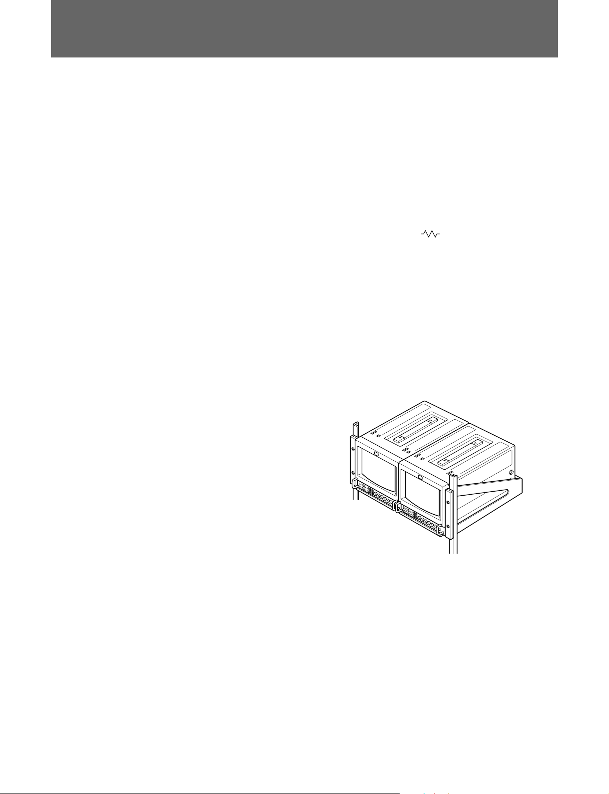
By using an MB-520 mounting bracket (not supplied),
the monitor can be mounted in an EIA standard 19inch rack. For details on mounting, see the instruction
manual of the MB-520.
Multiple input signals
In addition to the composite video signals and the Y/C
signals, analog RGB signals and component signals
can be input.
External sync input
When the EXT SYNC button is pressed, the monitor
can be operated on the sync signal fed through an
external sync connector.
Blue only picture
Black and white apparent picture consisting from only
the blue signal will be displayed. This facilitates the
“chroma” and “phase” adjustment, and the observation
of the video noise.
16:9 selector
The monitor can display the 16:9 signal with the
correct ratio of width and height, compressing the
picture vertically.
..........................................................................................................................................................................................................
1) SDI: Serial Digit Interface
2) An NTSC4.43 signal is used for playing back NTSC-recorded video cassettes with a video tape recorder/player especially
designed for use with this system.
3) Trinitron is a trademark of Sony Corporation.
2 (GB)
Page 25
Location and Function of Parts and Controls
Front
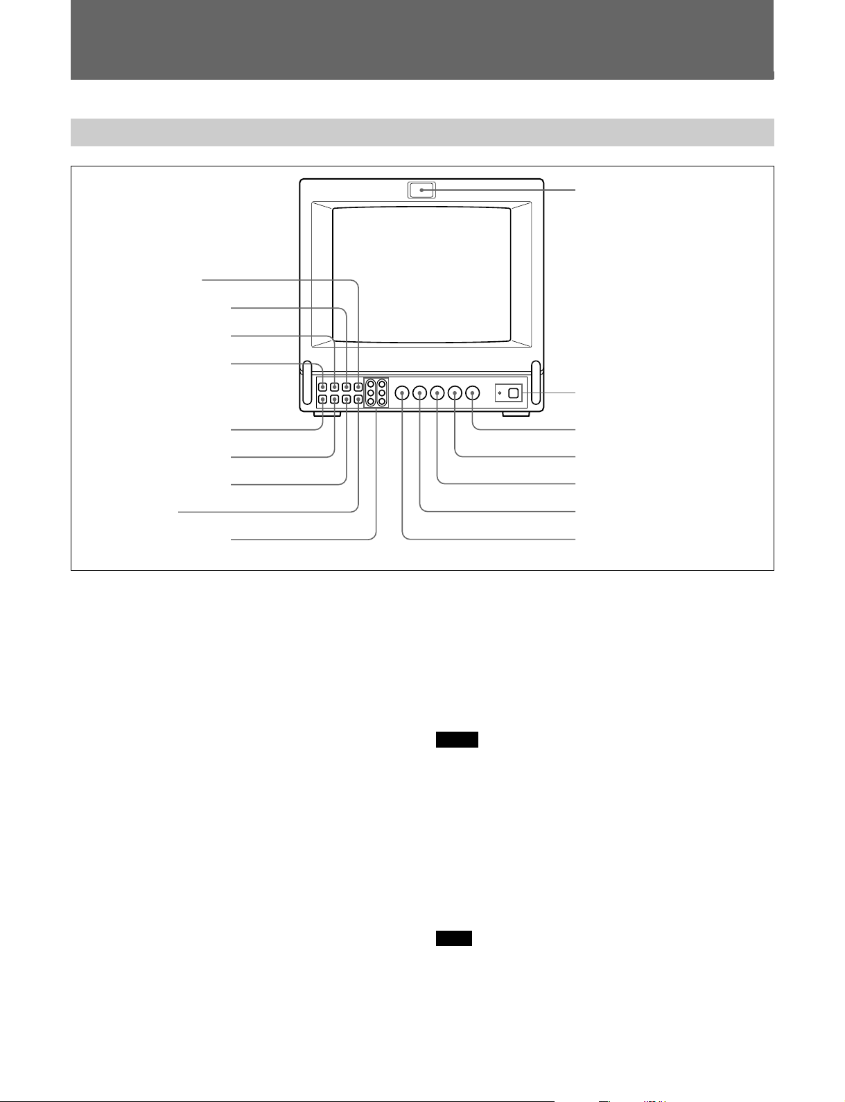
1 Tally lamp
8 DEGAUSS button
9 SYNC INT/EXT (sync
internal/external) selector
0 LINE/RGB input selector
qa A/B, SDI/RGB input
selector
2 POWER switch and indicator
qs BLUE ONLY selector
qd UNDER SCAN selector
qf H/V DELAY selector
qg 16:9 selector
qh R/G/B BIAS and GAIN
adjustment controls
1 Tally lamp
This indicator lights up. The tally control connection is
needed.
For the pin assignment, see “Specifications” on page 9 (GB).
2 POWER switch and indicator
Depress to turn the monitor on. The indicator will light
up in green.
The POWER indicator also functions as the external
power source indicator. When the power supplied
through the DC 12 V IN jack decreases, the indicator
flashes.
3 CONTR (contrast) control
Turn clockwise to make the contrast stronger and
counterclockwise to make it weaker.
4 PHASE control
This control is effective only for the NTSC and
4.43 color systems. Turn clockwise to make the
NTSC
skin tones greenish and counterclockwise to make
them purplish.
3 CONTR (contrast) control
4 PHASE control
5 CHROMA control
6 BRIGHT (brightness) control
7 APER (aperture) control
6 BRIGHT (brightness) control
Turn clockwise for more brightness and
counterclockwise for less.
7 APER (aperture) control
Turn clockwise for more sharpness and
counterclockwise for less.
Notes
•The PHASE control has no effect on the PAL system,
SECAM system, analog RGB signals, analog
component signals and digital component signals.
•The CHROMA and APER control have no effect on
the analog RGB signals.
8 DEGAUSS button
Press this button momentarily. The screen will be
demagnetized.
Note
If you press the DEGAUSS button again too soon, the
color shades may be uneven.
5 CHROMA control
Turn clockwise to make the color intensity stronger
and counterclockwise to make it weaker.
3 (GB)
Page 26

Location and Function of Parts and Controls
9 SYNC INT/EXT (sync internal/external) selector
Keep this button released (INT) to operate the monitor
on the sync signal from the displayed composite video
signal.
Depress this button (EXT) to operate the monitor on an
external sync signal fed through the EXT SYNC
connector on the rear panel.
When the digital component signal is selected, the
monitor is operated on the internal sync signal.
0 LINE/RGB input selector
This button selects the input signal to be monitored.
Depress this button (RGB) for a signal fed through the
COMPONENT SDI connectors or the RGB/
COMPONENT connectors. Keep this button released
(LINE) for a signal fed through the LINE A or LINE B
connectors.
qa A/B, SDI/RGB input selector
When the LINE/RGB input selector is set to LINE,
keep this button released (A) for a signal fed through
the LINE A connectors. Depress this button (B) for a
signal fed through the LINE B connectors.
When the LINE/RGB input selector button is set to
RGB,
this button selects the digital signal or the component
signal fed through the RGB input connectors on the
rear panel. Keep this button released (SDI) for the
digital signal. Depress this button (RGB) for the
component signal or the analog RGB signal.
When this button is depressed, the signal is selected by
setting the RGB/Y R-Y B-Y selector on the rear panel.
qs BLUE ONLY selector
Depress this button to turn off the red and green
signals. A blue signal is displayed as an apparent
monochrome picture on the screen. This facilitates
“chroma” and “phase” control adjustments and the
observation of video noise.
Note
The PHASE control adjustment is effective only for
NTSC system.
qd UNDER SCAN selector
Depress this button for underscanning. The display
size is reduced by approximately 3% so that four
corners of the picture are visible.
qf H/V DELAY selector
Depress this button to observe the horizontal and
vertical sync signals at the same time. The horizontal
sync signal is displayed in the left quarter of the
screen; the vertical sync signal is displayed near the
center of the screen.
qg 16:9 selector
Press this button to monitor the signals of 16:9 picture.
Pressing the UNDER SCAN selector qd in 16:9 mode
displays the whole 16:9 picture up to the four corners.
qh R/G/B BIAS and GAIN adjustment controls
Used for white balance fine adjustment.
BIAS and GAIN controls are provided for the R (red),
G (green) and B (blue) screens.
BIAS: Adjust the color temperature and brightness of
the screen at the lowlight.
GAIN: Adjust the color temperature and brightness of
the screen at the highlight.
To adjust them, use a screwdriver with a diameter of
3
2 mm (
/32 inch).
4 (GB)
Page 27
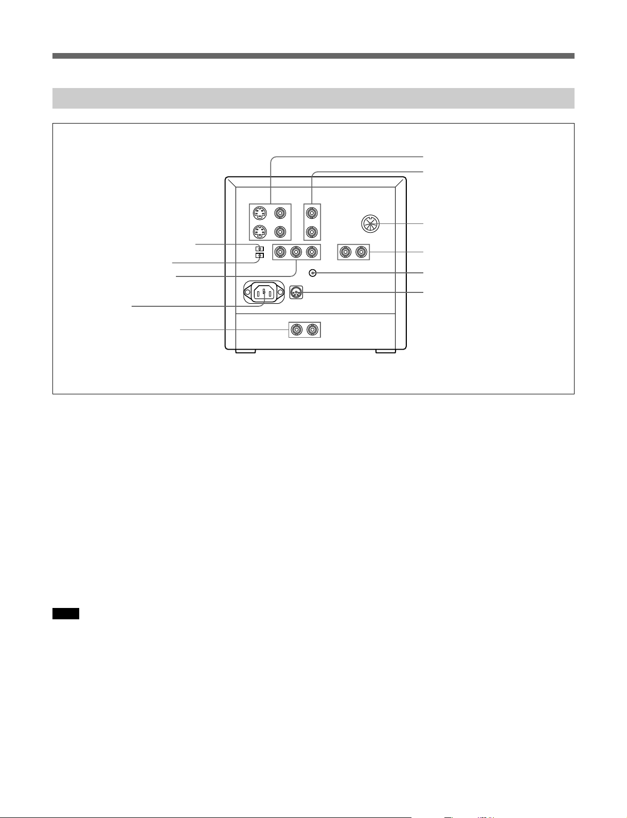
Rear
qj LINE A IN/OUT connectors
qk LINE B IN/OUT connectors
ql REMOTE connector (8-pin mini DIN)
wd COMPONENT LEVEL selector
wf RGB/Y R-Y B-Y selector
wg RGB/COMPONENT input
connectors (BNC)
wh AC IN socket
wj COMPONENT SDI IN/OUT
connectors (BNC)
qj LINE A IN/OUT connectors
To monitor the signal fed through these connectors,
keep the LINE/RGB input selector and the A/B, SDI/
RGB input selector released (LINE and A).
Y/C IN (4-pin mini DIN): Connect to the Y/C output
of a video camera, VCR or other video equipment.
Y/C OUT (4-pin mini DIN): Loop-through output of
the Y/C IN connector. Connect to the Y/C input of
a VTR or another monitor.
VIDEO IN (BNC): Connect to the video output of a
video camera, VTR or other video equipment.
VIDEO OUT (BNC): Loop-through output of the
VIDEO IN connector. Connect to the video input
of a VTR or another monitor.
Note
When a plug is connected to the Y/C IN connector, the
VIDEO IN connector is automatically disconnected.
qk LINE B IN/OUT connectors
To monitor the signal fed through these connectors,
keep the LINE/RGB selector released (LINE) and
depress the A/B, SDI/RGB input selector on the front
panel (B).
w; EXT SYNC (external sync)
connectors (BNC)
wa V HOLD (vertical hold) control
ws DC 12V IN jack (XLR, 4 pin)
VIDEO IN (BNC): Connect to the video output of a
video camera, VTR or other video equipment.
VIDEO OUT (BNC): Loop-through output of the
VIDEO IN connector. Connect to the video input
of a VTR or another monitor.
ql REMOTE connector (8-pin mini DIN)
Turning the tally lamp on or off and the input setting
are remotely controlled by connecting another
equipment to this connector.
For the pin assignment of this connector, see
“Specifications” on page 9 (GB).
w; EXT SYNC (external sync) IN/OUT connectors
(BNC)
To use these connectors, depress the SYNC INT/EXT
button on the front panel (EXT).
IN: When this monitor operates on an external sync
signal, connect the reference signal from a sync
generator to this connector. In this case, depress
the SYNC INT/EXT selector (EXT) on the front
panel.
OUT: Loop-through output of the EXT SYCN IN
connector. Connect to the external sync input of
video equipment to be synchronized with this
monitor.
5 (GB)
Page 28
Location and Function of Parts and Controls
wa V HOLD (vertical hold) control
Turn to stabilize the picture if it rolls vertically.
After the picture is stabilized, display another signals
and adjust this again so that the picture is stabilized
even when another signal is selected.
ws DC 12V IN jack (XLR, 4 pin)
Connect the DC 12 V power source to operate this
monitor.
wd COMPONENT LEVEL selector
Select the component level from among two modes.
N10/SMPTE: for 100/0/100/0 signal
BETA 0 : for 100/0/75/0 signal
wf RGB/Y R-Y B-Y selector
RGB: Set to this position to input the analog RGB
signal.
Y R-Y B-Y: Set to this position to input the
component signal.
wg RGB/COMPONENT input connectors (BNC)
To monitor a signal fed through these connectors,
depress the LINE/RGB input selector on the front
panel (RGB) and the A/B, SDI/RGB input button
(RGB). When the SYNC INT/EXT selector on the
front panel is released (INT), the monitor operates on
the sync signal from the G/Y channel.
•To monitor the analog RGB signal
Connect to the analog RGB signal outputs of a
video camera. Depress the A/B, SDI/RGB input
selector on the front panel (RGB).
Set the RGB/Y R-Y B-Y selector wf on the rear
panel to RGB.
•To monitor the component signal
Connect to the Y/R-Y/B-Y component signal
outputs of a Sony BetaCam video camera. Depress
the A/B, SDI/RGB input selector on the front
panel (Y R-Y B-Y). Set the RGB/Y R-Y B-Y
selector wf on the rear panel to Y R-Y B-Y.
wh AC IN socket
Connect the supplied AC power cord to this socket.
wj COMPONENT SDI IN/OUT connectors (BNC)
Depress the LINE/RGB input button (RGB) and
release the A/B SDI/RGB input button (SDI) on the
front panel.
IN: Inputs SMPTE 259M/CCIR 656-III 4:2:2 serial
digital signals from Digital BETACAM VTRs,
etc.
OUT: Outputs the digital signal of the equipment
connected to the COMPONENT SDI IN
connector (Active through).
We recommend to connect the following cable to
this connectors.
Coaxial cable:5C-2V (Max. 200 m, 656 feet)
Fujikura America Inc., Fujikura
Europe Ltd (FEL) or the equivalent
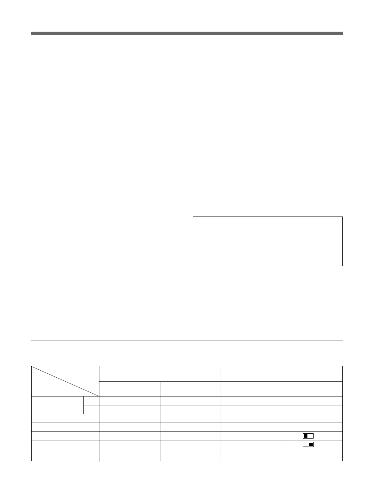
Relationships between the selectors, connectors and the input signal
The input signal is changed by the selectors and connectors on the front and rear panels as listed below.
Selectors and
connectors
Input signal A/B, SDI/RGB input LINE/RGB input Input connector RGB/Y R-Y B-Y
COMPOSITE
Y/C A 4 LINE 4 LINE A (Y/C) —
COMPONENT SDI SDI 4 RGB $ COMPONENT SDI —
ANALOG RGB RGB $ RGB $ RGB/COMPONENT RGB
COMPONENT
(Y R-Y B-Y)
selector qa selector 0 selector wf
AA 4 LINE 4 LINE A (VIDEO) —
BB $ LINE 4 LINE B —
RGB $ RGB $ RGB/COMPONENT R-Y
Front panel Rear panel
6 (GB)
Y
B-Y
Page 29
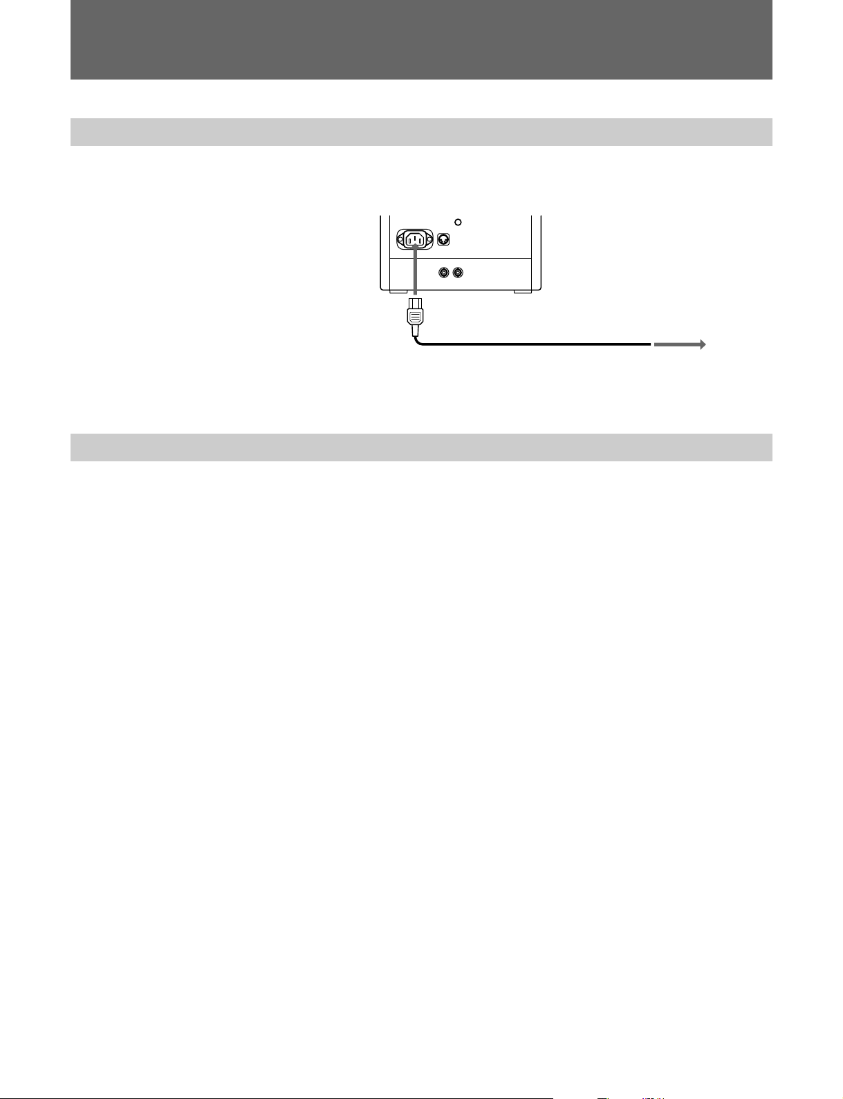
Power Sources
Using House Current
Using DC 12V IN jack
Connect the supplied AC power cord to the AC IN socket on the rear panel
and to a wall outlet.
to AC IN
to a wall outlet
When the AC power cord is plugged into the AC IN socket, the DC power
connected to the DC 12 V IN jack is automatically disconnected.
12V direct current is supplied through DC 12 V IN jack.
7 (GB)
Page 30

Specifications
Specifications
Video signal
Color system NTSC, PAL, SECAM, NTSC4.43
Resolution 450 TV lines
Aperture correction
–4.0 dB to +6.0 dB (at 3.0 MHz)
Frequency response
6.0 MHz (–3.0 dB)
Synchronization AFC time constant 1.0 msec.
Picture performance
Normal scan 6% over scan of CRT effective
screen area
Underscan 3% underscan of CRT effective
screen area
Linearity Less than 2.0%
Convergence Central area: 0.43 mm (typical)
Peripheral area: 0.53 mm (typical)
Raster size stability
H: 1.0%, V: 1.5%
High voltage regulation
3.0%
Color temperature D65
Inputs
COMPONENT SDI IN: BNC connector
Serial digital (270M bits/s)
SMPTE 259M/CCIR 656-III
Y/C IN: 4-pin mini DIN connector
See the pin assignment on page 9 (GB).
VIDEO IN: BNC connector
1 Vp-p, ± 6 dB, sync negative
R/R-Y, G/Y, B/B-Y: BNC connector
R, G, B channels: 0.7 Vp-p,
± 6 dB
Sync on green: 0.3 Vp-p,
negative, 75 ohms terminated
R-Y, Y, B-Y channels: 0.7 Vp-p,
±6 dB (Standard color bar signal
of 100% chrominance)
EXT SYNC IN: BNC connector
Composite sync 4 Vp-p, ±6 dB,
negative
Loop-through outputs
COMPONENT SDI OUT: BNC connector
Active through output
Serial digital (270M bits/s)
SMPTE 259M/CCIR 656-III
Y/C OUT: 4-pin mini DIN connector (75 ohms
automatic termination)
VIDEO OUT: BNC connector (75 ohms automatic
termination)
EXT SYNC OUT: BNC connector (75 ohms automatic
termination)
REMOTE input
REMOTE: 8-pin mini DIN connector
See the pin assignment on page 9 (GB).
General
Power consumption
BVM-8045QD:
48W max. at AC operation
44W at DC operation
BVM-9045D:
45W at AC operation
42W at DC operation
Power requirements
BVM-8045QD:
120 V AC, 50/60Hz
12 V DC with the AC-550
AC Adaptor (not supplied), etc.
BVM-9045D
100 to 240 V AC, 50/60 Hz
12 V DC with the AC-550CE
AC Adaptor (not supplied), etc.
Peak inrush current (BVM-9045D)
Hot switching inrush current, measured in
accordance with European
standard EN55103-1: 70A
(230V)
Operating conditions
Temperature 0 to +35°C (32 to 95°F)
Humidity 0 to 90% (no condensation)
Pressure 700 to 1060 hPa
8 (GB)
Page 31
Transport and storage conditions
Temperature –10 to +40°C
Humidity 0 to 90%
Pressure 700 to 1060 hPa
Dimensions Approx. 217 × 217 × 352.5 mm (w/
5
h/d) (8
/8 × 8 5/8 × 14 inches)
(not incl. projecting parts and
controls)
Mass Approx. 8.5 kg (18 lb 12 oz) (not
incl. battery packs)
Accessory supplied
AC power cord (1)
Cable with an 8-pin connector (1)
Operation Manual (1)
Tally plate (1)
AC plug holders (1)
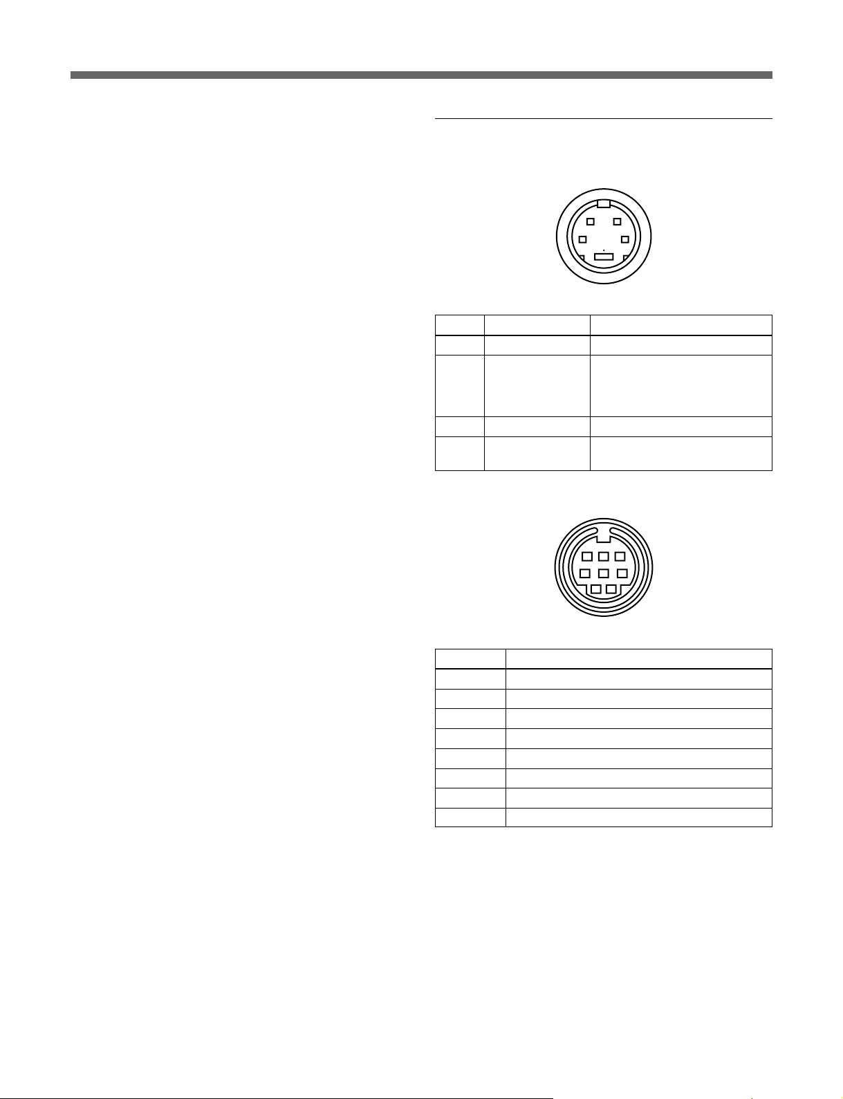
Pin Assignment
Y/C IN connector (4-pin mini DIN)
12
43
Pin No. Signal Description
1 Y-input 1 Vp-p, sync negative, 75 ohms
2 CHROMA 286 mVp-p (NTSC)
sub-carrier-input 300 mVp-p (PAL), burst
Delay time between Y and C:
within 0 ±100 nsec., 75 ohms
3 GND for Y-input GND
4 GND for
CHROMA-input
REMOTE connector (8-pin mini DIN)
GND
678
3
45
12
Pin No. Signal
14 : 3/16 : 9
2 H/V delay
3 GND
4 INT/EXT SYNC
5 Tally
6 Underscan/normal scan
7 A/B or SDI/LINE
8 LINE/RGB
For remote control, connect the pin of the desired
function to pin 3 (GND).
Design and specifications are subject to change
without notice.
9 (GB)
Page 32

BVM-8045QD
BVM-9045QD
BVM-9045D
(J/UC/AEP,
3-865-374-04(1)
和, 英
Printed in Japan
)
Sony Corporation
B&P Company
2002.07.13
1998
 Loading...