

Page 1

EDITING CONTROL UNIT
BVE-700A
INSTALLATION MANUAL
1st Edition (Revised 1)
Serial No. 10001 and Higher
Page 2

! WARNING
This manual is intended for qualified service personnel only.
To reduce the risk of electric shock, fire or injury, do not perform any servicing other than that
contained in the operating instructions unless you are qualified to do so. Refer all servicing to
qualified service personnel.
! WARNUNG
Die Anleitung ist nur für qualifiziertes Fachpersonal bestimmt.
Alle Wartungsarbeiten dürfen nur von qualifiziertem Fachpersonal ausgeführt werden. Um die
Gefahr eines elektrischen Schlages, Feuergefahr und Verletzungen zu vermeiden, sind bei
Wartungsarbeiten strikt die Angaben in der Anleitung zu befolgen. Andere als die angegeben
Wartungsarbeiten dürfen nur von Personen ausgeführt werden, die eine spezielle Befähigung
dazu besitzen.
! AVERTISSEMENT
Ce manual est destiné uniquement aux personnes compétentes en charge de l’entretien. Afin
de réduire les risques de décharge électrique, d’incendie ou de blessure n’effectuer que les
réparations indiquées dans le mode d’emploi à moins d’être qualifié pour en effectuer d’autres.
Pour toute réparation faire appel à une personne compétente uniquement.
Attention-when the product is installed in Rack:
1. Prevention against overloading of branch circuit
When this product is installed in a rack and is
supplied power from an outlet on the rack, please
make sure that the rack does not overload the supply
circuit.
2. Providing protective earth
When this product is installed in a rack and is
supplied power from an outlet on the rack, please
confirm that the outlet is provided with a suitable
protective earth connection.
3. Internal air ambient temperature of the rack
When this product is installed in a rack, please make
sure that the internal air ambient temperature of the
rack is within the specified limit of this product.
4. Prevention against achieving hazardous
condition due to uneven mechanical loading
When this product is installed in a rack, please make
sure that the rack does not achieve hazardous
condition due to uneven mechanical loading.
5. Install the equipment while taking the operating
temperature of the equipment into consideration
For the operating temperature of the equipment, refer
to the specifications of the Operation Manual.
6. When performing the installation, keep the
following space away from walls in order to
obtain proper exhaust and radiation of heat.
Front, Left : 10 cm (4 inches) or more
BVE-700A
Page 3

Table of Contents
Manual Structure
Purpose of this manual ........................................................... 2 (E)
Related manuals .....................................................................2 (E)
Contents .................................................................................. 2 (E)
Trademarks ............................................................................. 2 (E)
1. Installation
1-1. Operating Environment ........................................... 1-1 (E)
1-2. Power Supply ........................................................... 1-1 (E)
1-3. Installation Space ..................................................... 1-2 (E)
1-4. Matching Connectors and Cables ............................ 1-4 (E)
1-5. Input/Output Signals of Connectors ........................ 1-5 (E)
1-6. Function of Switch and LED on Board ................... 1-7 (E)
1-7. Rack Mounting ........................................................ 1-9 (E)
1-8. Installing the BKE-701A ....................................... 1-10 (E)
2. Service Overview
2-1. Removing/Reinstalling Front Panel ......................... 2-1 (E)
2-2. Cleaning ................................................................... 2-1 (E)
2-2-1. Filter ............................................................... 2-1 (E)
2-2-2. Fan .................................................................. 2-1 (E)
2-3. Data Backup Capacitor ............................................ 2-2 (E)
BVE-700A
1 (E)
Page 4

Purpose of this manual
Related manuals
Manual Structure
This manual is the installation manual of Editing Control Unit BVE-700A.
This manual is intended for use by trained system and service engineers, and
describes the information on installing the BVE-700A.
Beside this Installation Manual, the following manuals are available for the unit.
..
. User’s Guide (Supplied with BVE-700A)
..
This manual describes the application and operation of the unit.
..
. Operation Manual (Supplied with BVE-700A)
..
This manual describes the overview, system connection examples, and specifications of the unit.
..
. BKE-701A Installation Manual (Supplied with BKE-701A)
..
This manual describes the information related to the installation of the unit.
Contents
..
. BVE-700A/BKE-701A Maintenance Manual (Available on request)
..
This manual describes the information that premise the service of BVE-700A/
BKE-701A based on components replaced.
..
. “Semiconductor Pin Assignments” CD-ROM (Available on request)
..
This “Semiconductor Pin Assignments” CD-ROM allows you to search for
semiconductors used in B&P Company equipment.
The maintenance manual contains a complete list of semiconductors and their ID
Nos., and thus should be used together with the CD-ROM.
Part number: 9-968-546-XX
This manual is organized by following sections.
Section 1 Installation
This section describes the operating environment, power supply, installation space,
installation of optional board, rack mounting, connectors, input and output signals of
connectors, switch settings on board and LED description.
Section 2 Service Overview
This section describes the cleaning and the capacitor for backing up the data.
Trademarks
2 (E)
Trademarks and registered trademarks used in this manual are follows.
. Ethernet is a registered trademark of Xerox Corporation.
BVE-700A
Page 5
Section 1
For customers in the U.S.A. and Canada
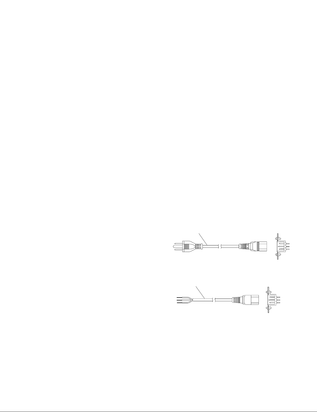
1 Power cord, 125 V 10 A (2.4 m) : ! 1-557-377-11
AC inlet
1
Installation
1-1. Operating Environment
Operating guaranteed temperature : +5 dC to +40 dC
Performnace guaranteed temperature : +10 dC to +35 dC
Operating humidity : 10 % to 90 %
(relative humidity)
Storage temperature : _20 dC to +60 dC
Mass : Processor unit 12 kg
(with BKE-701A
installed)
Control panel 4.5 kg
Prohibited locations
. Areas where the unit will be exposed to direct sunlight or
any other strong lights.
. Dusty areas
. Areas where it is subject to vibration.
. Areas with strong electric or magnetic fields.
. Areas near heat sources.
. Areas where is subjected to electricity noise.
. Areas where is subjected to static electricity noise.
Ventilation
The inside of the BVE-700A is air-cooled by a fan (on left
side).
The power supply can be damaged if the exhaust vent (left
side panel) and air intake (front panel) are blocked or the
fan is stopped.
Therefore, leave a blank space of more than 10 cm in the
front and left side of the BVE-700A.
2. Recommended Power Cord
The power cord is not supplied with the BVE-700A.
To get a power cord, please contact your local Sony Sales
Office/Service Center.
w
. Use the approved Power Cord (3-core mains lead)/
Appliance Connector/Plug with earthing-contacts that
conforms to the safety regulations of each country if
applicable.
. Use the Power Cord (3-core mains lead)/Appliance
Connector/Plug conforming to the proper ratings (Voltage, Ampere).
If you have questions on the use of the above Power Cord/
Appliance Connector/Plug, please contact your local Sony
Sales Office/Service Center.
w
. Never use an injured power cord.
. Plugging the power cord in the AC inlet, push as far as it
will go.
1-2. Power Supply
1. Power specifications
A switching regulator is used for the power supply of this
unit. The voltage within the range of 100 V to 240 V can
be used without changing the supply voltage.
Power requirements : AC 100 to 240 V ± 10 %
50/60 Hz
Current consumption : Maximum AC100 V ; 1 A
Maximum AC240 V ; 0.5 A
(with all optional boards installed)
n
As the inrush current at turn-on is the maximum 35 A (at
100 V/85 A (at 240 V), the capacity of the AC power must
be commensurate in it.
If the capacity of the AC power is not the adequately large,
the breaker of the AC power at the supply side will operate
or the unit will abnormally operate.
BVE-700A
For customers in the all European countries
1 Power cord, 250 V 10 A (2.4 m) : ! 1-782-929-22
1
AC inlet
1-1 (E)
Page 6
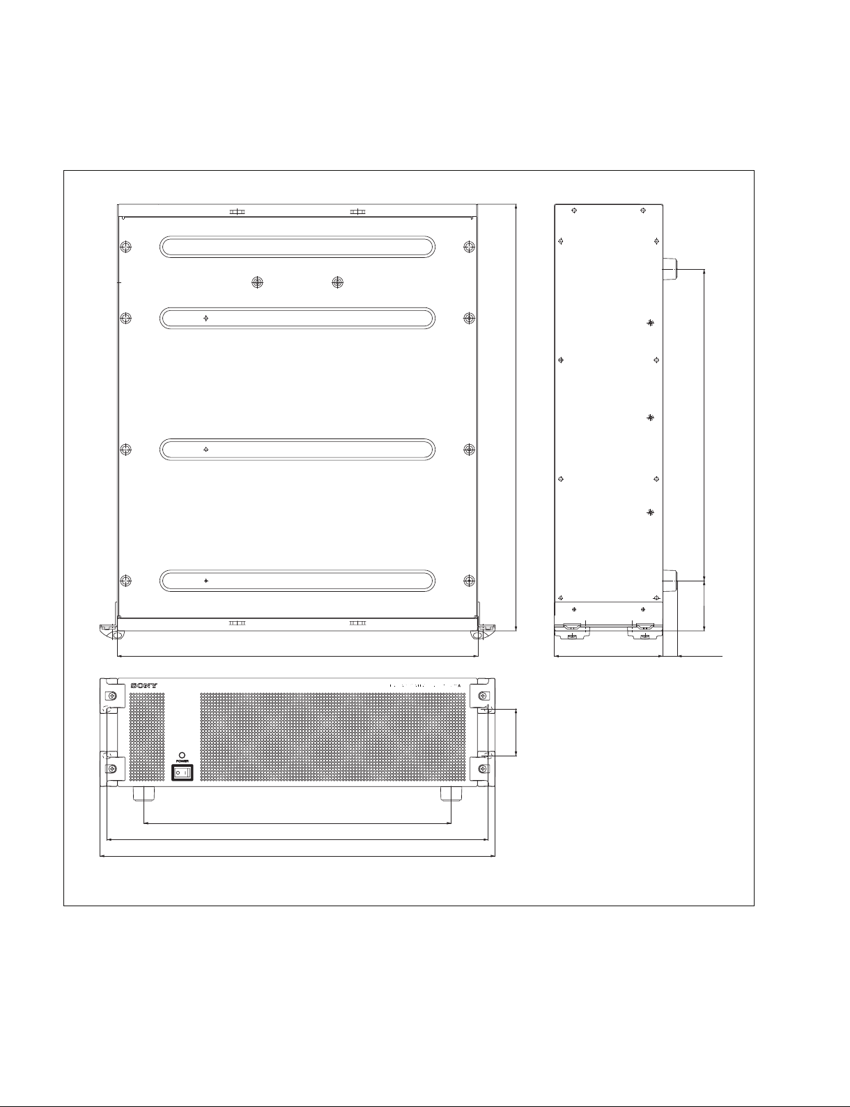
1-3. Installation Space
Processor unit
520
440
375
465
482
57.2
132.4
61 380
17.5
Unit : mm
1-2 (E)
BVE-700A
Page 7
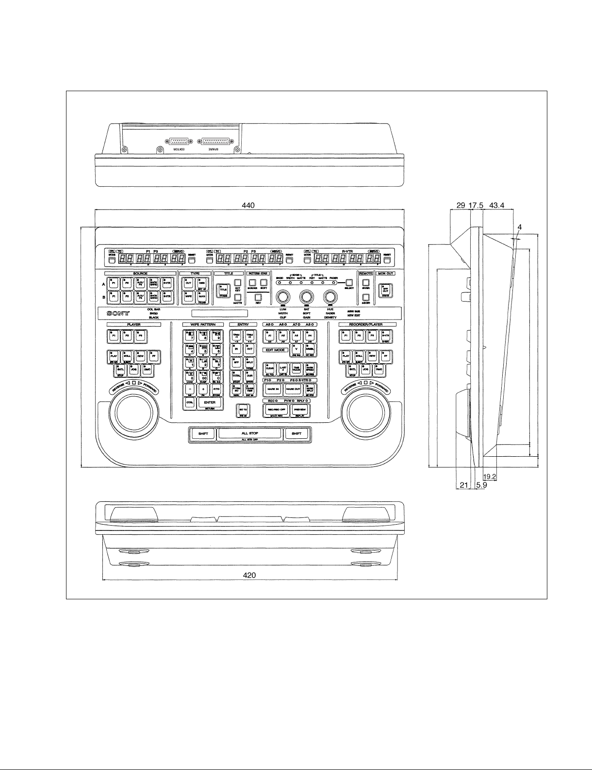
Control panel unit
340
315.5
281
277.2
16.9
Unit : mm
315
15
BVE-700A
1-3 (E)
Page 8

1-4. Matching Connectors and Cables
Use the following connectors, cables, or equivalents when connecting cables to the unit.
Panel indication Connector name Matching connector and cable
Name Sony part No.
Processor unit
PLAYER-1 D-sub 9-pin, Female D-sub 9-pin, Male
PLAYER-2 Connector 9-pin, Male 1-560-651-00
PLAYER-3 Junction Shell 9-pin 1-561-749-00
RECORDER
MIXER
SWER
Processor unit
EDL D-sub 9-pin, Male D-sub 9-pin, Female
Connector 9-pin, Female 1-563-815-21
Junction Shell 9-pin 1-561-749-00
Processor unit
GPI D-sub 15-pin, Female D-sub 15-pin, Male
Connector 15-pin, Male 1-564-600-11
Junction Shell 15-pin 1-563-376-11
Processor unit
SDI IN BNC, 75 Z BNC, 75 Z
SDI OUT 5C-FB coaxial cable
Processor unit
REF VIDEO BNC, 75 Z BNC, 75 Z
Belden 8281 coaxial cable
Processor unit/Control panel unit
PANEL D-sub 15-pin, Female D-sub 15-pin, Male
Connector 15-pin, Male 1-564-600-11
Junction Shell 15-pin 1-563-376-11
Processor unit
NETWORK RJ-45 modular jack
*1 : To use plugs, the following crimp contacts are required.
AWG #18 to #22 : 1-566-493-21
AWG #22 to #24 : 1-564-774-11
AWG #24 to #30 : 1-564-775-11
*2 : Conforms to the IEEE 802.3 Ethernet 10BASE-T/100BASE-TX standards.
*2
__
*1
*1
*1
1-4 (E)
BVE-700A
Page 9
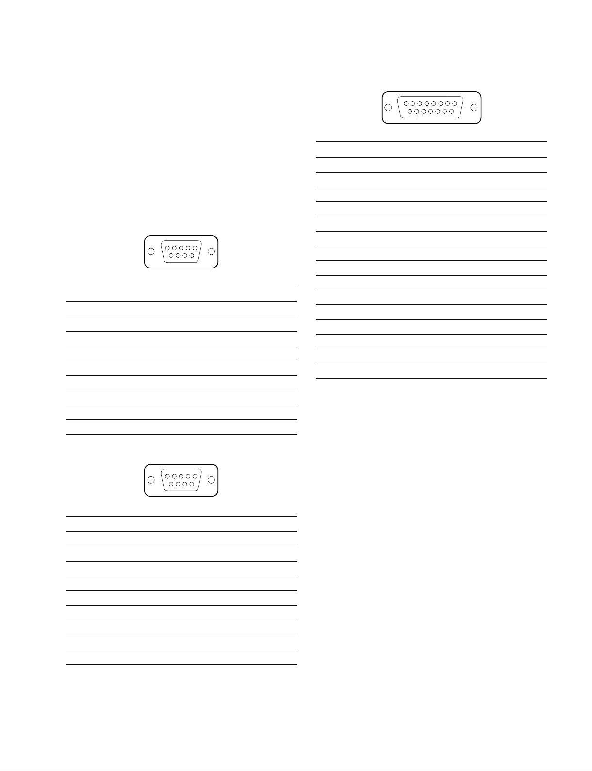
1-5. Input/Output Signals of Connectors
GPI : D-sub 15-pin, Female
The input/output signals of the connectors at the rear panel
are as follows.
. Processor unit
PLAYER-1
PLAYER-2
PLAYER-3
RECORDER
MIXER
SWER : RS-422A (D-sub 9-pin, Female)
5
_ EXT VIEW _
Pin No. Signal Function
1 GND Ground
2RX_ Received data (_)
3TX+ Transmitted data (+)
4 GND Ground
5 _ No Connection
6 GND Ground
7 RX+ Received data (+)
8TX_ Transmitted data (_)
9 _ No Connection
1
69
8
15
_ EXT VIEW _
Pin No. Signal Function
1 GND Ground
2 OUT-1A Relay output-1A
3 OUT-2A Relay output-2A
4 OUT-3 (TTL) Open collector output-3
5 OUT-4 (TTL) Open collector output-4
6 IN-1 (TTL) Input-1
7 IN-3 (TTL) Input-3
8 GND Ground
9 OUT-1B Relay output-1B
10 OUT-2B Relay output-2B
11 _ No Connection
12 _ No Connection
13 GND Ground
14 IN-2 (TTL) Input-2
15 IN-4 (TTL) Input-4
1
9
EDL : RS-232C (D-sub 9-pin, Male)
1
_ EXT VIEW _
Pin No. Signal Function
1 _ No Connection
2 RXD Received data
3 TXD Transmitted data
4 _ No Connection
5 GND Ground
6 _ No Connection
7 RTS (Not used at present)
8 CTS (Not used at present)
9 _ No Connection
5
96
BVE-700A
1-5 (E)
Page 10
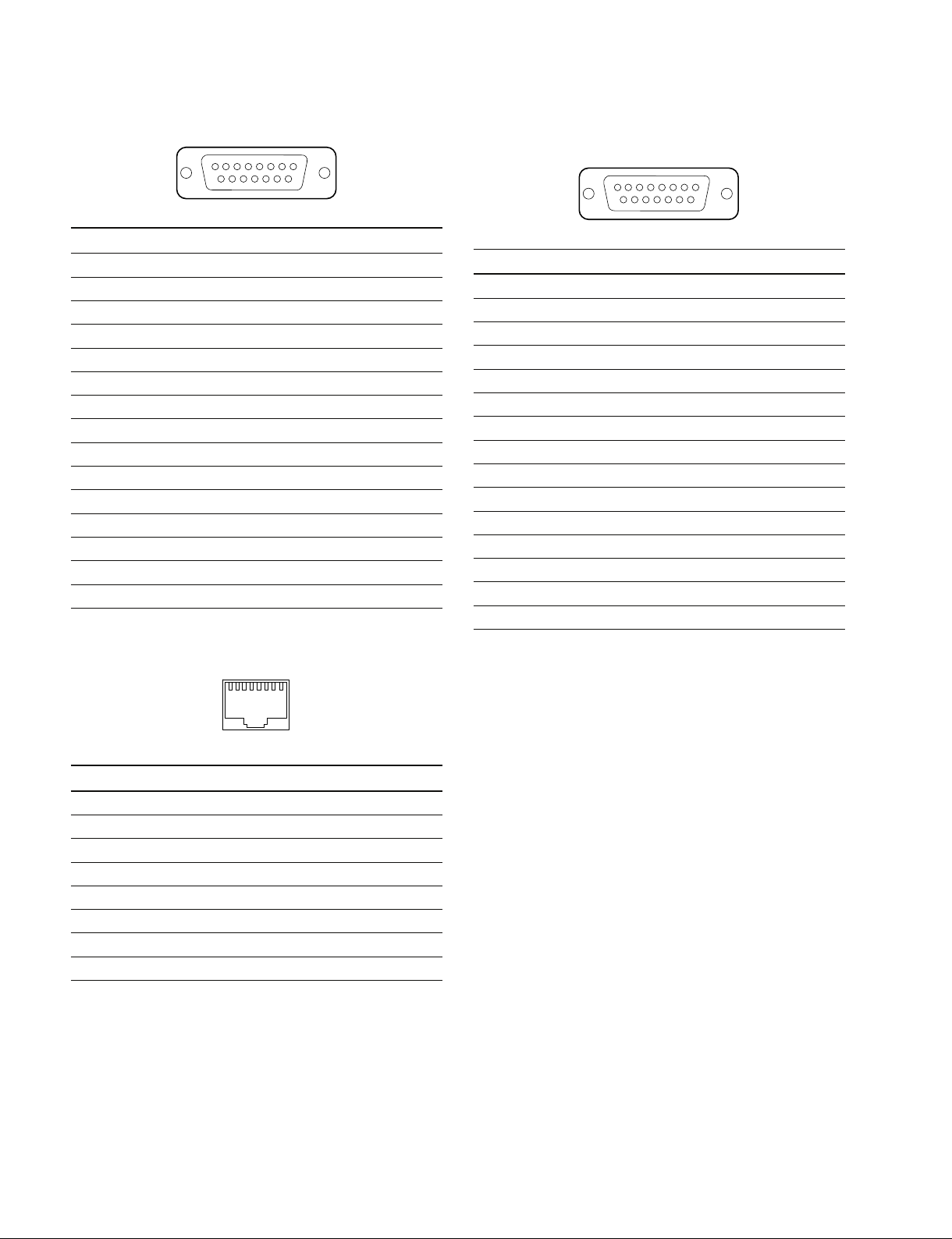
PANEL : D-sub 15-pin, Female
8
15
_ EXT VIEW _
Pin No. Signal Function
1 GND Ground
2RX_ Received data (_)
3TX+ Transmitted data (+)
4 GND Ground
5 _ No Connection
6 12 V Panel Power Supply
7 12 V Panel Power Supply
8 12 V Panel Power Supply
9 _ No Connection
10 RX+ Received data (+)
11 TX_ Transmitted data (_)
12 GND Ground
13 GND Ground
14 GND Ground
15 GND Ground
1
9
. Control panel unit
EDITOR : D-sub 15-pin, Female
8
15
_ EXT VIEW _
Pin No. Signal Function
1 GND Ground
2RX_ Received data (_)
3TX+ Transmitted data (+)
4 GND Ground
5 _ No Connection
6 12 V Panel Power Supply
7 12 V Panel Power Supply
8 12 V Panel Power Supply
9 _ No Connection
10 RX+ Received data (+)
11 TX_ Transmitted data (_)
12 GND Ground
13 GND Ground
14 GND Ground
15 GND Ground
1
9
NETWORK : 10BASE-T/100BASE-TX (8-pin, Modular jack)
1
_ EXT VIEW _
Pin No. Signal Function
1TX+ Transmitted data (+)
2TX_ Transmitted data (_)
3RX+ Received data (+)
4 _ No Connection
5 _ No Connection
6RX_ Received data (_)
7 _ No Connection
8 _ No Connection
8
1-6 (E)
BVE-700A
Page 11
OPEN
1
234
5
6
78
Factory setting
( indicates the knob position.)
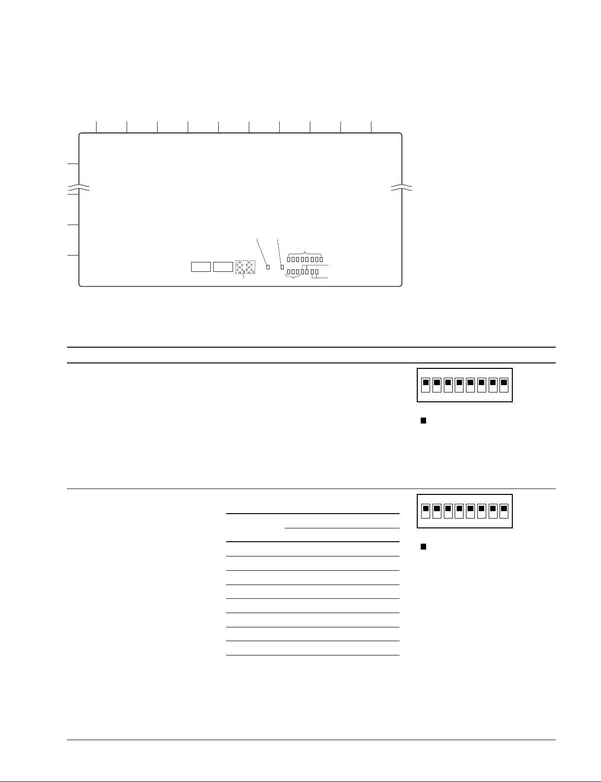
1-6. Function of Switch and LED on Board
OPEN
1
234
5
6
78
Factory setting
( indicates the knob position.)
CA-67 board
A
B
F
1234567891011
G
H
S900 S901
D900-D915
D1702D1700
D930-D937
D940-D942
D1000, D1001
D1502, D1500
Switches
n
Do not change the setting of the “Factory use” switches.
Ref. No. Address Name Function
S900 (H-7) Mode select Sets the operation mode when starting up.
S901 (H-6) Mode select Sets the operation mode.
switch (1) S900-1 : Sets the operation mode.
OPEN : Normal mode
CLOSE : Installation mode
S900-2 : Sets the operation mode.
OPEN : Normal mode
CLOSE : Diagnostic mode
S900-3 : Factory use
S900-4 : Factory use
S900-5 : Factory use
S900-6 : Factory use
S900-7 : Factory use
S900-8 : Factory use
switch (2) S901-1 to S901-5 : Sets the Video Format.
Video Format S901
-1 -2 -3 -4 -5
1125/59.94 OFF OFF OFF OFF OFF
1125/29.97 PsF OFF OFF OFF OFF ON
525/59.94 OFF OFF OFF ON OFF
1125/50 OFF ON ON OFF OFF
1125/25 PsF OFF ON ON OFF ON
625/50 OFF ON ON ON OFF
1125/24 PsF ON OFF ON OFF ON
1125/23.98 PsF ON OFF OFF OFF ON
OFF : OPEN
ON : CLOSE (Push the switch to the DOWN position)
Any switch setup other than the these shown on
the above table is invalid.
S901-6 : Factory use
S901-7 : Setup status
OPEN : Normal operation
CLOSE : The machine starts up with the setup of USER SETUP DATA1 state.
Side A (component side)
m
. Reference inputs B.B and Try Sync
are detected automatically.
. For 1125/59.94 and 1125/50, Ref
Lock is applied to both B.B and Try
Sync reference inputs.
. The BKE-701A switcher board does
not support the SD format.
BVE-700A
1-7 (E)
Page 12

LEDs
Ref. No. Adress Name Function Normal state
D900 to (H-6) _ 7SEG LED 00
D915 Error status indication.
Normal: Displays 00.
When an error occurs: Displays an error code.
(See Maintenance Manual for details.)
D930 (H-4) SW_ACT Status indication of SWER on the rear panel. Lights up
D931 (H-4) MIX_ACT Status indication of MIXER on the rear panel. Lights up
D932 (H-4) P1_ACT Status indication of PLAYER-1 on the rear panel. Lights up
D933 (H-4) P2_ACT Status indication of PLAYER-2 on the rear panel. Lights up
D934 (H-4) P3_ACT Status indication of PLAYER-3 on the rear panel. Lights up
D935 (H-3) REC_ACT Status indication of RECORDER on the rear panel. Lights up
D936 (H-3) PNL_ACT Status indication of PANEL on the rear panel. Lights up
D937 (H-3) EDL_ACT Status indication of EDL on the rear panel. Lights off
D940 (H-4) 3.3 V 3.3 V power supply status indication. Lights up
D941 (H-4) 5 V 5 V power supply status indication. Lights up
D942 (H-4) 12 V 12 V power supply status indication. Lights up
D1000 (H-4) REF_EXT Lights up in green when a signal is input to REF Lights up
D1001 (H-4) PLL_LOCK Lights up in green when the reference signal is Lights up
D1500 (H-3) ETHER_100 Lights up in green when the mode of NETWORK Lights off
D1502 (H-3) ETHER_ACT Lights up in green when communication is Lights off
D1700 (H-5) TEMP Blinks in green when the temperature in Lights off
D1702 (H-4) FAN Lights up in green when the temperature in Lights off
FAST the BVE-700A turns 45 °C or higher.
Lights up in green when the SWER communication
system can be operated correctly at startup.
Lights up in green when the MIXER communication
system can be operated correctly at startup.
Lights up in green when the PLAYER-1 communication system can be operated correctly at startup.
Lights up in green when the PLAYER-2 communication system can be operated correctly at startup.
Lights up in green when the PLAYER-3 communication system can be operated correctly at startup.
Lights up in green when the RECORDER communication system can be operated correctly at startup.
Lights up in green when the PANEL communication
system can be operated correctly at startup.
Lights up in green when sending data.
Lights up in green when 3.3 V power is supplied.
Lights off at error.
Lights up in green when 5 V power is supplied.
Lights off at error.
Lights up in green when 12 V power is supplied.
Lights off at error.
VIDEO IN on the rear panel and is correctly
recognized.
locked.
is set to 100 Mbps base.
established through NETWORK on the rear (when network is not
panel. connected)
the BVE-700A turns 85 °C or higher.
At the same time, TEMP ERROR is displayed
on the scratchpad on the control panel.
1-8 (E)
BVE-700A
Page 13
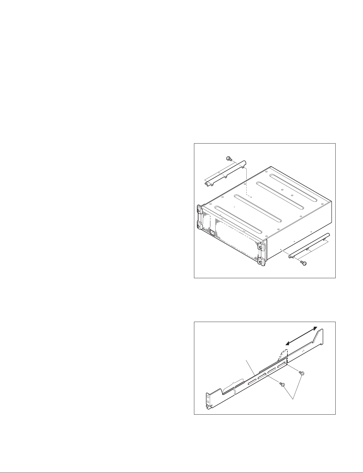
1-7. Rack Mounting
B4 x 6
B4 x 6
The BVE-700A is mounted in the 19-inch standard rack.
To mount the BVE-700A in the rack, use the specified rack
mount kit and follow the procedure described below.
Specified rack mount kit : RMM-10
n
If a rack mount kit other than the specified one is used, the
unit may not be mounted in the 19-inch standard rack.
Parts of the RMM-10
. Rack tools 2 pcs
. Right rack mount adapter 1 pc
. Left rack mount adapter 1 pc
. Rack tool attaching screws 6 pcs
(B4 x 6 : 7-682-560-09)
. Rack tool attaching screws 6 pcs
(B4 x 10 : 7-682-560-10)
1. Precautions for rack mounting
w
. To prevent the rack from falling or moving, fix the rack
on a flat and steady floor using bolt or others.
If the rack falls due to the weight of the equipment, it
may cause death or injury.
. Be sure to use the specified rack mount kit.
If not, injury may result and the equipment may fall due
to insufficient strength.
. After rack mounting, be sure to tighten the screws on the
rack angle and fix the unit in the rack.
If the screws on the rack angle are not tightened, the unit
may slip from the rack and fall, causing injury.
c
When mounting the unit in the rack, note the following:
. Be sure to mount in the rack with two persons or more.
. Be careful not to catch your fingers or hands in the rack
mount rail or others.
. Mount in the rack in a stable position.
2. Rack mounting procedure
This section describes the rack mounting procedure using
the RMM-10 rack mount kit.
n
Tighten the screws to the following torque.
Tightening torque : 120 x 10_2 N.m {12.2 kgf.cm}
1. Attach the rack tool to the side of the equipment using
the specified six screws.
n
Use B4 x 6 screws.
2. Loosen the screws on the rear of the right and left
adapters and adjust the length of the adapter according
to the depth of the rack.
(The illustration below shows the left adapter.)
Adapter
n
If several units are mounted in a rack, it is recommended to
install a ventilation fan to prevent temperature rise inside
the rack.
BVE-700A
Portion of
the rail
B4 x 6
n
Maximum depth of adapter : 750 mm
Minimum depth of adapter : 595 mm
1-9 (E)
Page 14
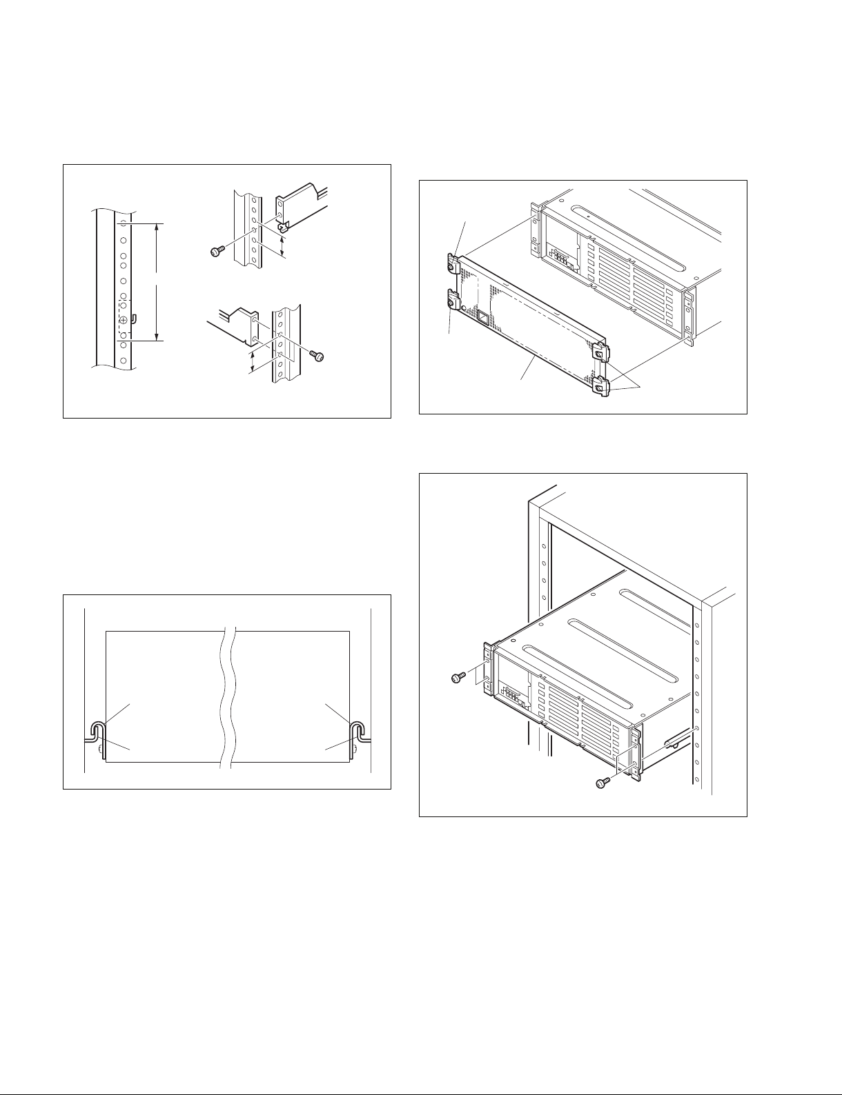
3. Attach the right and left adapters to the rack completely using the specified six screws.
(The illustration below shows the left adapter.)
6. Turn off the main power of this unit and disconnect the
plug from the outlet.
7. Fully loosen the four screws (with drop-safe) and
remove the front panel.
B4 x 10
(with drop-safe)
B4 x 10
3U
31.75
31.75
B4 x 10
Unit : mm
4. Tighten the screws (B4 x 6 : two screws each on the
right and left) for adjusting the length of the adapter
completely (the screws that were loosened in step 2).
5. Align the groove of the rack tool at the side of the
equipment with the rail, and slide the equipment to the
rear.
n
The rack tools are hooked on the rails as shown below.
B4 x 10
(with drop-safe)
Front panel
B4 x 10
(with drop-safe)
8. Fix the rack angle in the rack using the specified
screws.
1-10 (E)
Rack tool
Rail Rail
Rack tool
B5 x 12
B5 x 12
9. Attach the front panel to the equipment.
1-8. Installing the BKE-701A
For the installation procedure, refer to “4. Installing the
BKE-701A” of the Installation Manual supplied with the
BKE-701A.
BVE-700A
Page 15
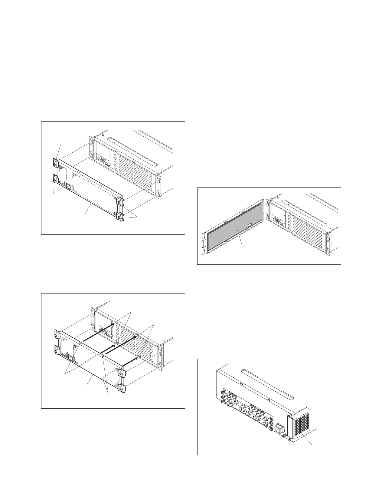
Section 2
Service Overview
2-1. Removing/Reinstalling Front Panel
Removal
1. Turn off the main powers of the processor and disconnect the AC power cords from the wall outlet.
2. Tighten the four screws (with drop-safe) and remove
the front panel.
B4 x 10
(with drop-safe)
B4 x 10
(with drop-safe)
Front panel
B4 x 10
(with drop-safe)
2-2. Cleaning
2-2-1. Filter
The filter on the rear of the front panel can easily accumulate the dust. Be sure to remove dust by cleaning as
follows.
1. Remove the front panel. (Refer to Section 2-1.)
2. Remove the dust accumulated on the filter with a
vacuum cleaner.
n
Cleaning the filter by washing in water is recommended when there is a heavy accumulation of dust.
Be sure to dry the filter completely after it has been
washed.
Reinstallation
Insert the front panel securely into the chassis and tighten
the four screws (with drop-safe).
n
To install the front panel, fit the protrusions of the chassis
into the grooves in the front panel.
Protrusions
Protrusions
Grooves
Front panel
Grooves
Filter
2-2-2. Fan
Processor is air-cooled by a fan (on side).
If dust has accumulated in the intake of the fan, air is
prevented from flowing smoothly and this may result in a
temperature rise inside the machine. This may have an
adverse effect on performance and the life of the machine.
Cleaning of the fan every month is recommended.
Contact your local Sony Sales Office/Service Center for
information on cleaning the fan.
BVE-700A
Fan
2-1 (E)
Page 16

2-3. Data Backup Capacitor
A large capacitor is installed on the CA-67 board in order
to retain the various data in the BVE-700A machine.
Leave the main power of the BVE-700A turned on for
about four hours or longer in order to charge this capacitor.
The data is retained for four to five days when the capacitor is fully charged under normal operating temperature
and humidity. However, this period may vary depending
on the storage environment. Be sure to save necessary data
in an external media.
2-2 (E)
BVE-700A
Page 17

The material contained in this manual consists of
information that is the property of Sony Corporation.
Sony Corporation expressly prohibits the duplication of
any portion of this manual or the use thereof for any
purpose other than the operation or maintenance of the
equipment described in this manual without the express
written permission of Sony Corporation.
Le matériel contenu dans ce manuel consiste en
informations qui sont la propriété de Sony Corporation.
Sony Corporation interdit formellement la copie de
quelque partie que ce soit de ce manuel ou son emploi
pour tout autre but que des opérations ou entretiens de
l’équipement à moins d’une permission écrite de Sony
Corporation.
Das in dieser Anleitung enthaltene Material besteht aus
Informationen, die Eigentum der Sony Corporation sind.
Die Sony Corporation untersagt ausdrücklich die
Vervielfältigung jeglicher Teile dieser Anleitung oder den
Gebrauch derselben für irgendeinen anderen Zweck als
die Bedienung oder Wartung der in dieser Anleitung
beschriebenen Ausrüstung ohne ausdrückliche
schriftliche Erlaubnis der Sony Corporation.
BVE-700A
Page 18

BVE-700A (SY) J, E
3-991-224-02
Printed in Japan
Sony Corporation 2007. 9 16
©2005
 Loading...