

Sony Bravia XBR-75X910C, BraviaXBR-65X900C, Bravia XBR-55X900C Reference Manual
Television
Reference Guide
US
Téléviseur
Manuel de référence
Sony Customer Support
U.S.A.:
http://www.sony.com/tvsupport
Canada:
http://www.sony.ca/support
United States Canada
1.800.222.SONY 1.877.899.SONY
Please Do Not Return the Product to
the Store
FR
XBR-75X910C / 65X900C / 55X900C
Service à la clientèle Sony
Canada :
http://support.sony.ca/fr
États-Unis :
http://www.sony.com/tvsupport
Canada États-Unis
1.877.899.SONY 1.800.222.SONY
Ne retournez pas le produit au magasin
Table of Contents
IMPORTANT NOTICE . . . . . . . . . . . . . . . . 2
Safety information . . . . . . . . . . . . . . . . . 3
Precautions . . . . . . . . . . . . . . . . . . . . . . . 6
Parts and Controls . . . . . . . . . . . . . . . .8
Controls and Indicators . . . . . . . . . . . . . 8
Inputs and Outputs . . . . . . . . . . . . . . . . 9
Using Remote Control . . . . . . . . . . . . 11
Remote Control Parts Description. . . . 11
Using the Touchpad Remote
Control. . . . . . . . . . . . . . . . . . . . . . . . . . 13
Launching the Touchpad Remote
Control Introduction/Tutorial. . . . . . . . 13
Attaching the Table-Top Stand
(Alternative) . . . . . . . . . . . . . . . . . . . .14
Connecting the TV . . . . . . . . . . . . . . .16
Showing a Set Top Box with
COMPONENT connection. . . . . . . . . . . 16
Connecting MHL Device. . . . . . . . . . . . 17
Showing HD BRAVIA® Sync™ Basic
Connection . . . . . . . . . . . . . . . . . . . . . . 18
Showing HD Basic Connection with
Home Theater System . . . . . . . . . . . . . 19
Showing PC Connection with SD
VCR/DVD . . . . . . . . . . . . . . . . . . . . . . . . 20
Installing the TV to the Wall . . . . . . . 21
Using the supplied Wall-Mount
Bracket. . . . . . . . . . . . . . . . . . . . . . . . . . 21
Using an optional Wall-Mount
Bracket. . . . . . . . . . . . . . . . . . . . . . . . . . 27
Installing the TV against a wall or
enclosed area. . . . . . . . . . . . . . . . . . .29
Troubleshooting. . . . . . . . . . . . . . . . 30
Troubles and Solutions . . . . . . . . . . . .30
Specifications . . . . . . . . . . . . . . . . . . . 31
Introduction
Thank you for choosing this Sony product.
Before operating the TV, please read this manual
horoughly and retain it for future reference.
t
Note
• Images and illustrations used in Startup Guide and this
manual are for reference only and may differ from actual
product appearance.
The 75 class has a 74.5 inch
(189.3 cm) viewable image size,
t
he 65 class has a 64.5 inch
(163.9 cm) viewable image size
and the 55 cla
ss has a 54.6 inch
(138.8 cm) viewable image size
(measured diagonally).
Location of the identification label
Labels for the Model No. and Power Supply rating are
located on the rear of the TV.
IMPORTANT NOTICE
Owner’s Record
The model and serial numbers are located at the side
and rear of the TV. Record these numbers in the spaces
provided below. Refer to them whenever you call upon
your Sony dealer regarding this TV.
Model Name
Serial No.
CAUTION
To prevent electric shock and blade exposure, do not use
this AC plug with an extension cord, receptacle or other
outlet unless the blades can be fully inserted.
• Operate the TV only on 110-240 V AC (U.S.A./Canada 120 V
)
AC
• Some people may experience discomfort (such as eye
rain, fatigue, or nausea) while watching 3D video
st
images or playing stereoscopic 3D games. Sony
recommends that all viewers take regular breaks while
watching 3D video images or playing stereoscopic 3D
games. The length and frequency of necessary breaks will
vary from person to person. You must decide what works
best. If you experience any discomfort, you should stop
watching the 3D video images or playing stereoscopic 3D
games until the discomfort ends; consult a doctor if you
believe necessary. You should also review (i) the
instruction manual of any other device or media used
with this television and (ii) our website
(http://www.sony.com/tvsupport) for the latest
ormation. The vision of young children (especially
inf
those under six years old) is still under development.
Consult your doctor (such as a pediatrician or eye doctor)
before allowing young children to watch 3D video images
or play stereoscopic 3D games. Adults should supervise
young children to ensure they follow the
recommendations listed above.
• Do not use, store, or leave the 3D Glasses or battery near
ire, or in places with a high temperature, e.g., in direct
a f
sunlight, or in sun-heated cars.
US
2
Safety information
U-shaped Bar
U-shaped Bar
Declaration of Conformity
Trad e Nam e: SO NY
Model: XBR-75X910C/XBR-65X900C/XBR-55X900C
Responsible Party: Sony Electronics Inc.
Address: 16530 Via Esprillo,
San Diego, CA 92127 U.S.A.
Telephone Number: 858-942-2230
This device complies with part 15 of the FCC rules.
ation is subject to the following two conditions:
Oper
(1) This device may not cause harmful interference, and
2) this d evice must accept any interference received,
(
including interference that may cause undesired
operation.
FCC Related Information
This equipment has been tested and found to comply with
the limits for a Class B digital device, pursuant to Part 15 of
the FCC Rules. These limits are designed to provide
reasonable protection against harmful interference in a
residential installation. This equipment generates, uses and
can radiate radio frequency energy and, if not installed and
used in accordance with the instructions, may cause
harmful interference to radio communications. However,
there is no guarantee that interference will not occur in a
particular installation. If this equipment does cause harmful
interference to radio or television reception, which can be
determined by turning the equipment off and on, the user
is encouraged to try to correct the interference by one or
more of the following measures:
• Reorient or relocate the receiving antenna.
• Increase the separation between the equipment and
ceiver.
re
• Connect the equipment into an outlet on a circuit
erent from that to which the receiver is connected.
diff
• Consult the dealer or an experienc
for help.
Pursuant to FCC regulations, you are cautioned that any
hanges or modifications not expressly approved in this
c
manual could void your authority to operate this
equipment.
ed radio/TV technician
Note
This television includes a QAM demodulator which should
allow you to receive unscrambled digital cable television
programming via subscription service to a cable service
provider. Availability of digital cable television
programming in your area depends on the type of
programming and signal provided by your cable service
provider.
WALL-MOUNT BRACKET
Below information shows the correct handling of the WallMount Bracket. Be sure to read this information thoroughly
and use the Wall-Mount Bracket correctly.
To Customers:
Be sure to observe the following precautions for safety to
event a serious injury through fire, electric shock, the
pr
product toppling over, or the product dropping.
• Be sure to subcontract the installation to licensed
ontractors and keep small children away during
c
installation.
• Be sure to subcontract moving or dismounting of the TV
licensed contractors.
to
• Do not remove screws, etc., after mounting the TV.
• Do not make alterations to the parts of the Wall-Mount
acket.
Br
• Do not mount any equipment other than the specified
oduct.
pr
• Do not apply any load other than the TV on the Wall-
unt Bracket.
Mo
• Do not lean on or hang from the TV.
• Do not handle the TV with excessive force during cleaning
maintenance.
or
To Sony Dealers and Contractors:
The following instructions are for Sony dealers and
c
ontractors only. Be sure to read safety precautions
described below and pay special attention to safety during
the installation, maintenance and checking of this product.
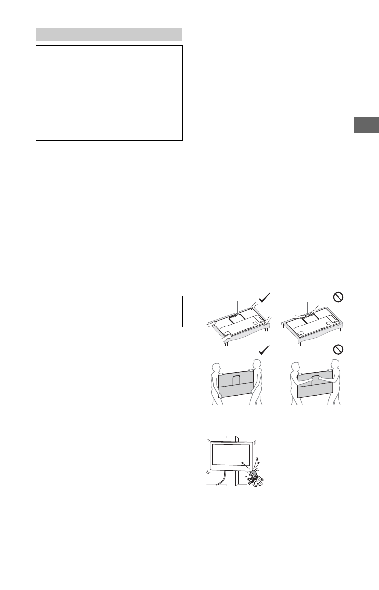
• When handling or mounting the TV set, hold it on the
des. Do not lift the TV by the U-shaped Bar.
si
US
Safety and Regulatory
This device complies with Industry Canada licence-exempt
RSS standard(s). Operation is subject to the following two
conditions: (1) this device may not cause interference, and
(2) this device must accept any interference, including
interference that may cause undesired operation of the
device.
To prevent radio interference to the licensed service, this
e is intended to be operated indoors and away from
devic
windows to provide maximum shielding. Equipment (or its
transmit antenna) that is installed outdoors is subject to
licensing.
Only use Wireless LAN indoors when using it with IEEE
2.11a (5 GHz).
80
This equipment complies with FCC/IC radiation exposure
limits set forth for uncontrolled equipment and meets the
FCC radio frequency (RF) Exposure Guidelines in
Supplement C to OET65 and RSS-102 of the IC radio
frequency (RF) Exposure rules. This equipment has very low
levels of RF energy that it deemed to comply without
maximum permissive exposure evaluation (MPE). But it is
desirable that it should be installed and operated with at
least 20 cm and more between the radiator and person’s
body (excluding extremities: hands, wrists, feet and
ankles).
This device and its antenna(s) must not be co-located or
operating with any other antenna or transmitter except
Grant condition.
• Do not install the Wall-Mount Bracket on wall surfaces
e the corners or the sides of the TV are protruding
wher
away from the wall surface.
• Do not install the TV over or under an air-conditioner.
US
3
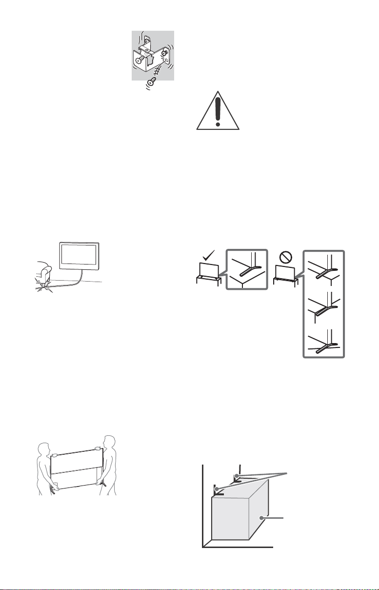
• Be sure to install the Wall-Mount
Angle brace
(not supplied)
Stand
Bracket securely to the wall
following the instructions in this
instruction manual. If any of the
screws are loose or fall out, the
Wall-Mount Bracket may fall and
cause injury or property damage.
• Be sure to use the screws supplied
ith the Wall-Mount Bracket when
w
attaching the Wall-Mount Bracket
to the TV set. The supplied screws
are designed as indicated by
illustration when measured from the attaching surface of
the Wall-Mount Bracket.
The diameter and length of the screws differ depending
all-Mount Bracket model.
on the W
Use of screws other than those supplied may result in
ernal damage to the TV set or cause it to fall, etc.
int
See page 21 (Using the supplied Wall-Mount Bracket).
See page 27 (Using an optional Wall-Mount Bracket).
• Be sure to assemble the bracket properly following the
ructed procedure explained in this instruction manual.
inst
• Be sure to tighten the screws securely in the designated
sition.
po
• Be careful not to subject the TV to shock during
tion.
installa
• Be sure to install the TV on a wall that is both
pendicular and flat.
per
• After proper installation of the TV, secure the cables
operly.
pr
• Do not allow the AC power cord or the connecting cables
ched as the internal conductors may become
to be pin
exposed and cause a short circuit or an electrical break.
Before setting up your TV
Some TV models are packaged with a detached Table-Top
Stand so you can mount your TV to a wall right away. See
page 21 (Installing the TV to the Wall) if you want to mount
the TV to a wall. If you are not mounting the TV to a wall,
ed to attach the Table-Top Stand. You will need a
you will ne
Phillips screwdriver (not supplied) and the supplied screws
omplete the task. Look for the supplied Table-Top Stand
to c
instruction leaflet.
Be sure to consider the following while setting up your TV:
• Disconnect all cables when carrying the TV.
• Carry the TV with the adequate number of people; larger
e TVs require two or more people.
siz
• To avoid slipping and causing personal injury, do not step
V protection bag when unpacking the TV set.
on the T
• Pay attention so that a child does n
Table-Top Stand installation.
• Correct hand placement while carrying the TV is very
portant for safety and to avoid damage.
im
ot approach during the
• Avoid moving the TV from a c
Sudden room temperature changes may cause moisture
condensation. This may cause the TV to show poor
picture and/or poor color. Should this occur, allow
moisture to evaporate completely before powering the TV
on.
old area to a warm area.
Securing the TV
Sony strongly recommends taking
measures to prevent the TV from
toppling over.
Unsecured TVs may topple and result
operty damage, serious bodily
in pr
injury or even death.
Preventing the TV from Toppling
• Secure the TV to a wall and/or stand.
• Do not allow children to play or climb on furniture and TV
ts.
se
• Avoid placing or hanging items on the TV.
• Never install the TV on:
ippery, unstable and/or uneven surfaces.
sl
rniture that can easily be used as steps, such as a
fu
chest of drawers.
• Install the TV where it cannot be pulled, pushed, or
ed over.
knock
• Install the TV so that the T
protrudes out from the TV stand (not supplied). If the
Table-Top Stand protrudes out from the TV stand, it may
cause TV set to topple over, fall down, and cause personal
injury or damage to the TV.
• Route all AC power cords and connecting cables so that
e not accessible to curious children.
they ar
V’ s Tab le-To p Stan d do es n ot
Recommended Measures to Secure the
TV
Consider the following measures when securing your TV to
a Stand (not supplied).
1 Secure the Stand for the TV.
Make sure the Stand can adequately support the weight
the TV. Use two angle braces (not supplied) to secure
of
the stand. For each angle brace use the appropriate
hardware to:
• Attach one side of the angle brace to the wall stud.
• Attach the other side to the Stand.
• Ensure your TV has adequate ventilation, see page 29.
• For best picture quality, do not expose the screen to direct
ination or sunlight.
illum
• Avoid installing the TV in a room with reflective wall and
aterials.
floor m
US
4
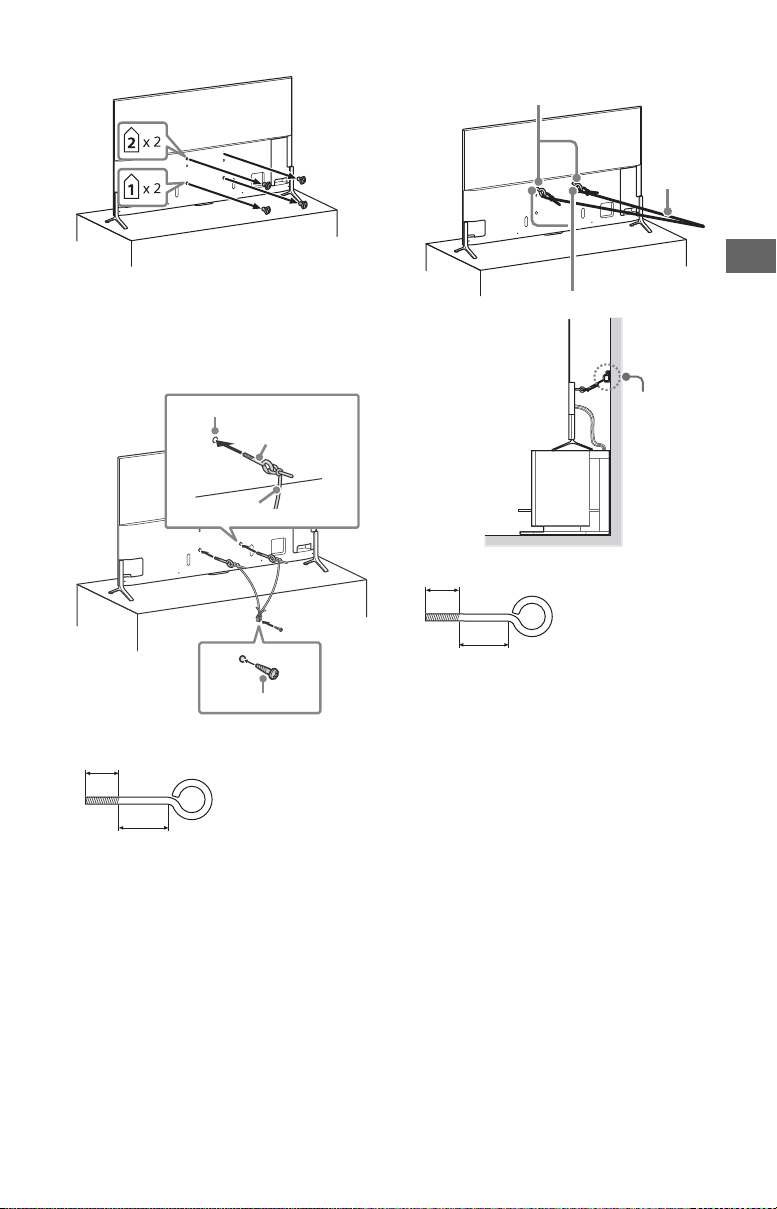
2 Remove the screws from the rear of the TV.
Screw hole on the rear cover
M6 eye bolt
(not supplied)
Rope or chain (not supplied)
Screw (not supplied)
8-12 mm
18 mm or more
M6 eye bolts (not supplied)
Screw holes
Rope or
chain (not
supplied)
Wall-anchor
(not supplied)
8-12 mm
18 mm or more
3 Secure the TV to the Stand.
Use the optional hardware listed as follows (not
supplied):
M6 eye bolt (screwed into the TV’s rear cover)
•
• A screw or similar (attach it to the Stand)
• Rope or chain (strong enough to support the weight of
the TV). Make sure that there is no excess slack in the
rope or chain.
4 Anchor the TV to the wall by using bolts, wall anchor and
chain (or rope).
Please see below illustration for M6 eye bolt length.
US
The length of the M6 eye bolt differs depending on the
ope or chain diameter. Please see below illustration.
r
Note
• Your TV is shipped with screws attached to the rear of the
TV depending on the TV model. (They are fastened in the
screw holes for wall mounting.) Be sure to remove the
upper two screws prior to anchoring the TV to a wall.
• Securing the TV to the stand without securing the TV and
stand to the wall provides minimum protection
the
against the TV toppling over. For further protection, be
sure to follow the three measures recommended.
5
US
Precautions
How to care for your BRAVIA TV
Safety is very important. Please read and follow the safety
documentation (Safety Booklet) separately provided.
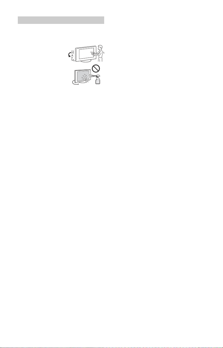
Unplug the TV and other
onnected equipment from
c
the wall outlet before you
begin cleaning your TV.
• W ipe the LCD screen gently
th a soft cloth.
wi
• Stubborn stains may be
emoved with a cloth
r
slightly moistened with a
solution of mild soap and
warm water.
• If using a chemically
etreated cloth, please follow the instruction provided
pr
on the package.
• Never spray water or detergent directly on the TV set. It
ay drip to the bottom of the screen or exterior parts and
m
enter the TV set, and may cause damage to the TV set.
• Never use strong solvents such as a thinner, alcohol or
or cleaning.
benzine f
• Do not plug in the TV into the wall outlet until the
ure from cleaning has evaporated.
moist
• Do not touch the TV if your hand is covered in any
ical substance such as hand cream or sunblock.
chem
The TV should also be placed on a stable surface to prevent
from toppling over (see page 4). If you have young
it
children or pets at home, check regularly to ensure the TV is
rely fastened.
secu
WALL-MOUNT BRACKET
• If you use the TV installed on the Wall-Mount Bracket for a
long time, the wall behind or above the TV may become
discolored or the wallpaper may come unglued,
depending on the material of the wall.
• If the Wall-Mount Bracket is removed after installing it on
he wall, the screw holes remain.
t
• Do not use the Wall-Mount Bracket in a place where it is
ted to mechanical vibration.
subjec
US
6
The BRAVIA® 4K TV Experience
Thank you for choosing Sony! Your new BRAVIA® TV
opens the door to the “4K TV Experience.” This
document will help you get the most out of your TV.
Please take a moment to register your TV at:
U.S.A.: h ttp://productreg istratio n.sony.com
Canada: http://www.sony.ca/registration
Four Steps to a 4K TV Experience
Set, Source, Sound, and Setup.
1 Set
Now that you have made the best selection in LED
cklit LCD TV technology, be sure to remove all of the
ba
accessories from the packaging before setting up your
TV.
2 Source
To experience the stunning detail of your BR
you need access to HD programming.
• Upgrade your signal or content source to high-
efinition (4K) by contacting your HD service provider.
d
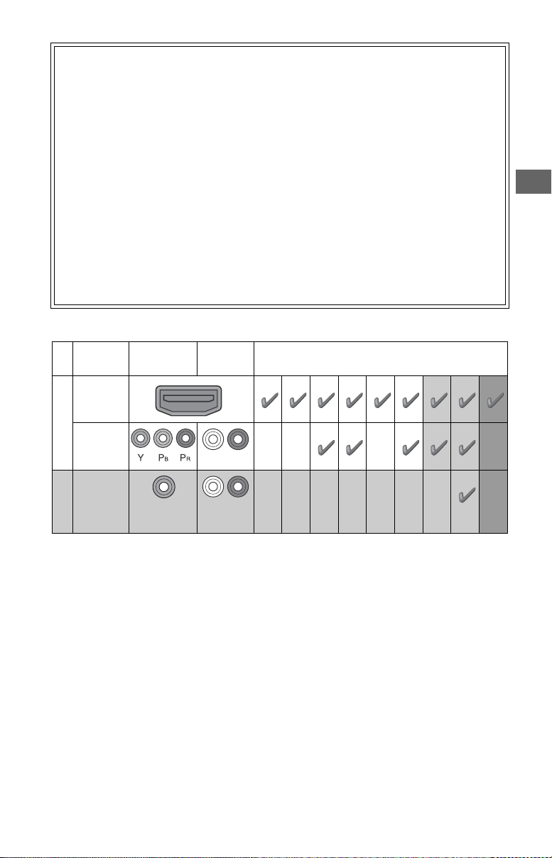
This TV displays all video input signals in a r
The following chart shows the high-definition (HD) and standard-definition (SD) video formats supported by your BRAVIA TV
inputs.
INPUT VIDEO AUDIO
AVIA TV,
esolution of 3,840 dots × 2,160 lines.
• Bring the astonishing resolution of your Sony 4K Ultra
H
D TV to life with Sony 4 K Ultra HD Media Player. (The
availability depends on region)
• Receive over-the-air HD broadcasts with an HD-
lity antenna connected directly to the back of your
qua
TV.
p://www.antennaweb.org for more
Visit htt
information on antenna selection and setup.
• Discover the wealth of entertainment now available
uper-high resolution Blu-ray Disc™ player and
on s
other Sony HD equipment.
3 Sound
Complete the high-definition experience with a BR
Sync™ surround sound system or A/V receiver from
Sony.
4 Setup
Install your TV and connect your sources. See page 16
for sample connection diagrams. To help assure the
est quality for your 4K experience, use Sony HDMI
high
(High-Definition Multimedia Interface) cables.
To learn more about 4K TV, visit:
U.S.A.: http://www.sony.com/HDTV
Canada: http://www.sony.ca/hdtv
4K*11080/
24p/30p
SUPPORTED FORMATS
1080p*11080i
720/
24p/30p
720p*1480p 480i PC*
AVIA
HDMI
4K/
HD
COMPONENT
Audio L/R
US
2
VIDEO
SD
*1 For details of supported formats, refer to the “Specifications” in this manual.
*2
For supported PC formats refer to the Help Guide.
Composite
video
connection
Audio L/R
US
7
Parts and Controls
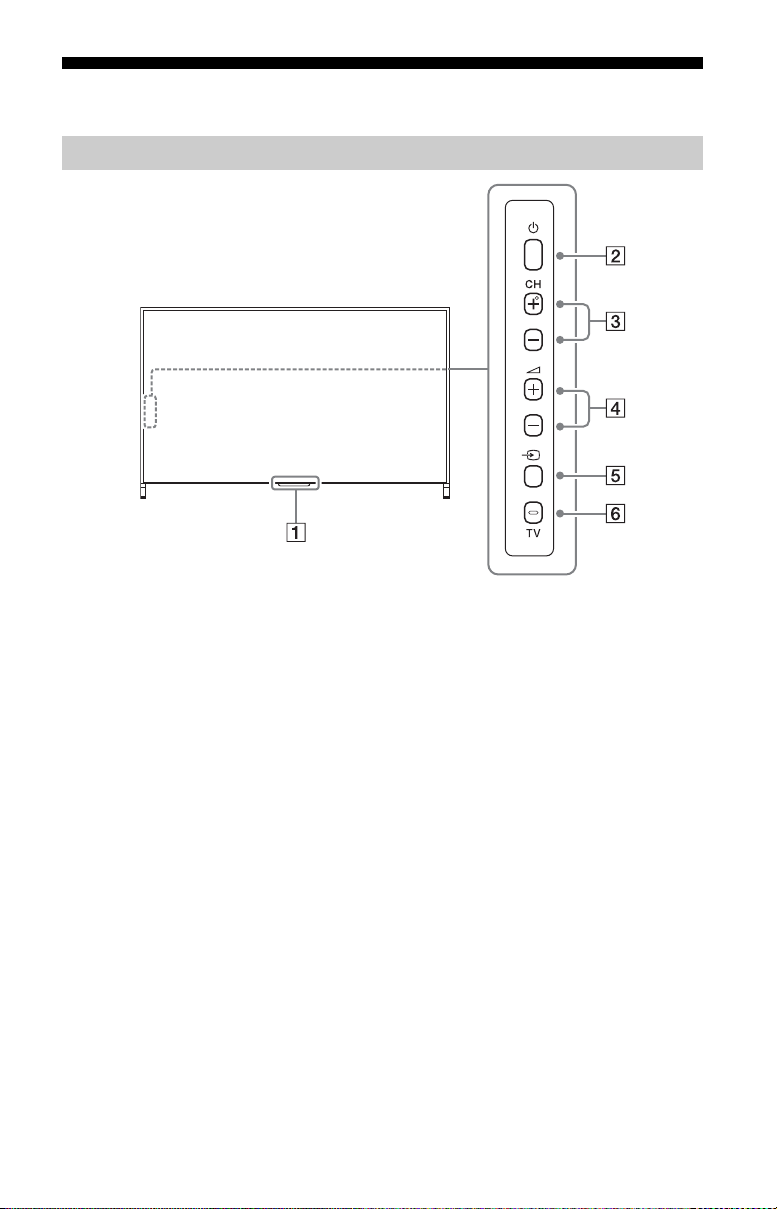
Controls and Indicators
Remote Control sensor* / Light
sensor*
/ Illumination LED / 3D Sync
Transmitter (XBR-75 X910C only)*
The illumination LED lights up or blinks
according to the status of the TV.
•White
When turning on the TV/picture off
mode/software update, etc.
•Cyan
When connecting with a mobile
device wirelessly.
•Amber
Timer is set.
(Power)
CH +/- (Channel)
+/- (Volume)
(Input select)
Display and select the input source.
US
8
TV
Switch to a TV channel or input from
other applications.
* Do not place anything near the sensor.
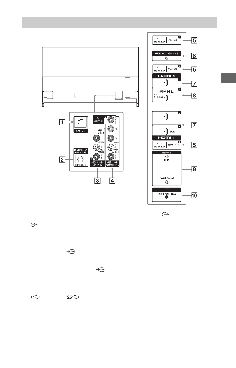
Inputs and Outputs
US
LAN
DIGITAL AUDIO OUT (OPTICAL)
/ VIDEO IN 1
For a composite connection*.
VIDEO IN 2, /
COMPONENT IN
• For a composite connection:
Use VIDEO IN, and (L/R) of /
COMPONENT IN*.
• For a component connection:
Use Y, PB, PR, and (L/R).
(USB 1/2), (USB 3)
• Connecting a large USB device may
interfere with other connected
devices beside it.
• When connecting a large USB device,
connect to the USB 1 jack.
AUDIO OUT /
• To listen to the TV's sound through
the connected equipment, press
HOME. Select [Settings] [Sound]
[Headphone/Audio out] and then
select the desired item.
HDMI IN 1/3/4
• If connecting a digital audio system
that is compatible with Audio Return
Channel (ARC) technology, use HDMI
IN 4. If not, an additional connection
with DIGITAL AUDIO OUT (OPTICAL) is
necessary.
HDMI IN 2/MHL
• You can connect your MHL (Mobile
High-definition Link) device using an
HD quality MHL cable.
US
9

REMOTE IR IN
REMOTE Serial Control
• These jacks are for receiving the
external control signal. Enables
extended control of the TV using
RS232C via the IR IN and Serial Control
jacks.
IR IN : connect to the IR out terminal
of the home controller.
Serial Control : connect to the RS232C
terminal of the home controller.
• Take care to not connect to
headphones or an external audio
system.
• If [RS232C control] is set to [On],
[BRAVIA Sync settings] is not
available.
CABLE/ANTENNA
Connect to your cable or antenna.
* When connecting mono equipment, connect to
the L (MONO) audio jack.
10
US
Using Remote Control
Ȫ
ȩ
ȫ
Ȭ
ȭ
Ȯ
ȯ
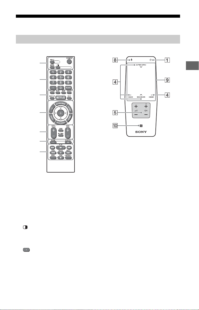
IR (infrared) Remote Control Touchpad Remote Control
Remote Control Parts Description
US
INPUT
Display and select the input source.
POWER/
Turn on or turn off the TV (standby
mode).
SYNC MENU
Display the BRAVIA Sync Menu.
(Twin picture/PIP)*1*
Display two pictures simultaneously.
2
Number buttons
Use with the 0-9 buttons to select
digital channels.
PIC OFF*
Turn the picture off, while sound
remains on.
2
Color buttons
Execute correspondent function at that
time.
DISPLAY
Display information about the channel/
program/input you are viewing.
NETFLIX
Access the “NETFLIX” online service.
HELP
Display Help Menu.
US
11
ACTION MENU
Display a list of contextual functions.
You can also display it by slide down
your finger from ACTION MENU on the
Touchpad Remote Control.
TV
Switch to a TV channel or input from
other applications.
1
GUIDE*
Display the digital program guide.
BACK
Return to previous screen.
HOME
Display the TV Home Menu.
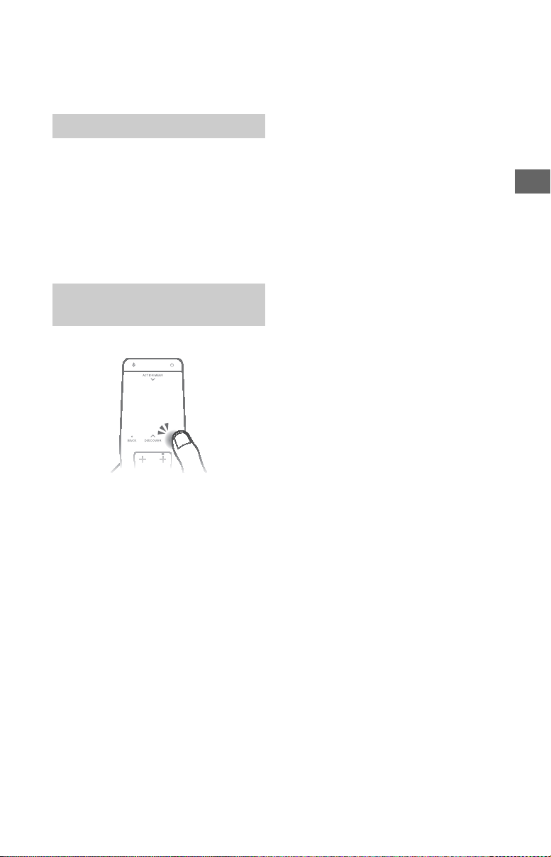
DISCOVER
Bring up the Content Bar to search for
content.
You can also launch Content Bar by
slide up your finger from DISCOVER on
the Touchpad Remote Control.
//// (Item select/Enter)
VOL +/– (Volume)
Adjust the volume.
JUMP
Jump back and forth between two
channels or inputs. The TV alternates
between the current channel or input
and the last channel or input that was
selected.
MUTING
Mute the sound. Press again to restore
the sound.
CH +/– (Channel)
Select the channel.
AUDIO
Change the language for the program
currently being viewed.
CC/SUBTITLE
Turn subtitles on or off (when the
feature is available).
//////
Operate media contents on TV and
connected BRAVIA Sync-compatible
device.
WIDE
Change the screen format.
FOOTBALL
Turn Live Football Mode on or off (when
the feature is available).
(Microphone)
Use Voice Function. (e.g., Search various
content by voice.)
To uchp ad
Operate the TV with the touchpad.
(NFC)
Touch the device (e.g. some models of
Xperia) corresponding to the One-touch
mirroring function, then its screen is
displayed on the TV.
*1 The location, availability and function of
remote control button may vary depending on
your country/region/TV model.
*2 Twin Picture/PIC OFF function will be available
from July 2015. You will receive Twin Picture/
PIC OFF function automatically as a network
software upgrade. Make sure your TV is
connected to the Internet. If you do not have a
network connection, you will be able to
download the software from the Sony support
website using your PC. For details on how to
upgrade, please visit the Sony support
website.
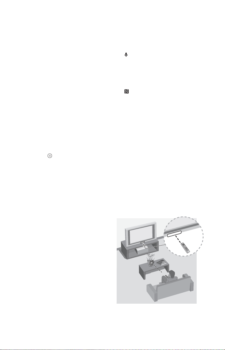
Guidelines for IR Remote Control
• Point your remote control directly at
the IR sensor located on your TV.
• Make sure that no objects are blocking
e path between the remote control
th
and the IR sensor on your TV.
• Fluorescent lamps can interfere with
our remote control; try turning off the
y
fluorescent lamps.
US
12
• If you are having problems with the
remote control, reinsert or replace your
batteries and make sure that they are
correctly inserted.
Using the Touchpad Remote Control
Touchpad Remote Control can only be used
after pairing with the TV.
To pair, follow the pairing screen
truction.
ins
Pairing screen can be displayed by pressing
the button on the TV for 5 seconds, or
select [Settings] - [Touchpad Remote
Control settings] - [Pair Touchpad Remote
Control].
Launching the Touchpad Remote Control Introduction/Tutorial
1 Press HOME.
US
2 Select [Settings] - [Touchpad
Remote Control settings] - [Start
Introduction/Tutorial].
US
13
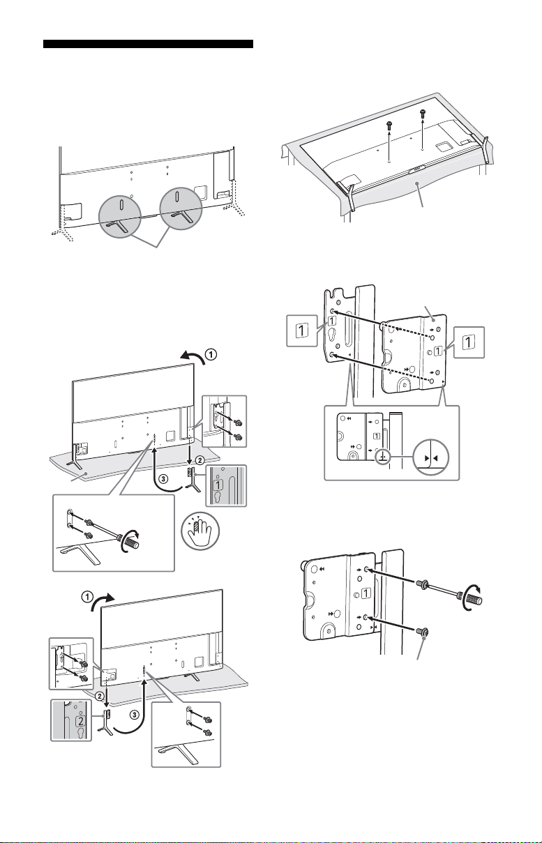
Attaching the Table-Top
Middle position
Thick cushion
1
1.5 N∙m/1,5 N∙m
{15 kgf∙cm}
2
Soft cloth
Stand plate
M5 × 10
1.5 N∙m/1,5 N∙m
{15 kgf∙cm}
Stand (Alternative)
You can change the Table-Top Stand from
the edge to the middle position by referring
to the instructions below.
Note
• Two or more people are needed to carry out this
installation.
• Be careful not to pinch the finger during
installa
tion.
XBR-75X910C/65X900C
XBR-55X900C
1 Remove the lower screws, and then
one of the Table-Top Stand.
2 Attach the stand plate (supplied
with the TV) to the detached TableTop S t a nd.
14
US
3 Fix the stand plate to the Table-Top
Stand with screws (M5×10) (supplied
with the TV).
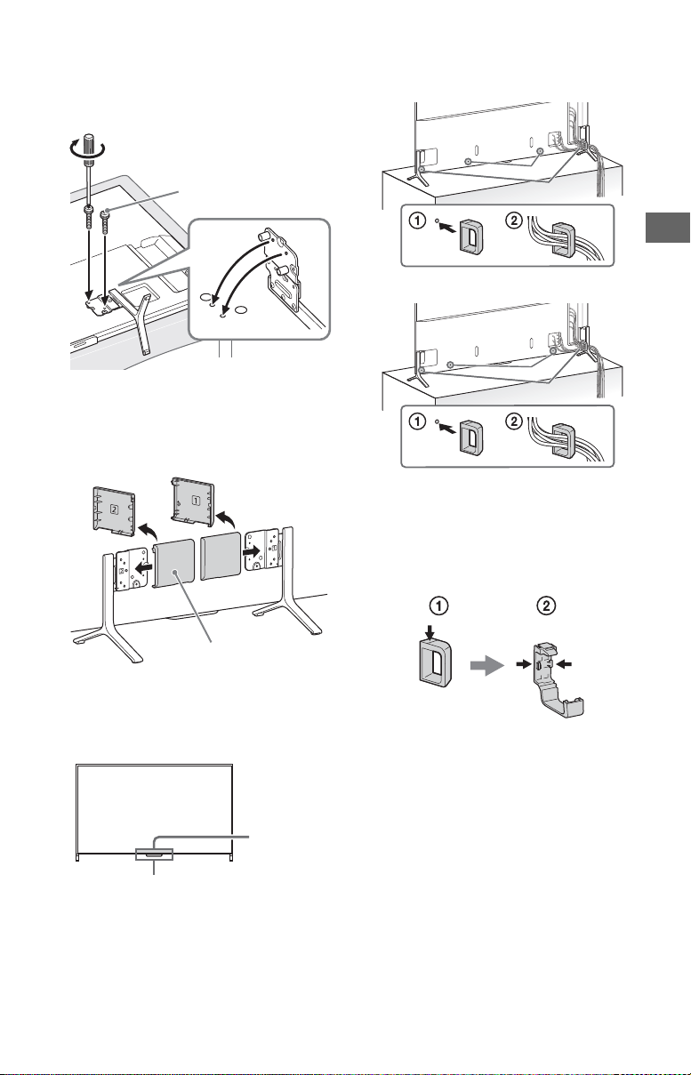
4 Attach the Table-Top Stand with
M6 × 32
1.5 N∙m/1,5 N∙m
{15 kgf∙cm}
Stand cover
IR Sensor
3D Sync
Tran smi tte r
(XBR75X910C
only)
*
2
*
1
*
2
*
1
stand plate to the middle position,
and fix with screws (M6×32)
(supplied with the TV.)
5 Take the same procedure for the
other side of the Table-Top Stand.
6 Attach stand covers (supplied with
the TV.)
To bu ndl e the cables
XBR-75X910C/65X900C
XBR-55X900C
*1 Location of cable clamper when the Table-Top
Stand is attached to middle position.
*2 Location of cable clamper when the Table-Top
Stand is attached to edge position.
Note
• To detach the cable clamper from the TV, press
the top of the clamper , then pinch as
illustrated.
US
Note
• Two or more people are needed to carry out this
installation.
• Ensure that there are no objects in front of the
TV
.
US
15
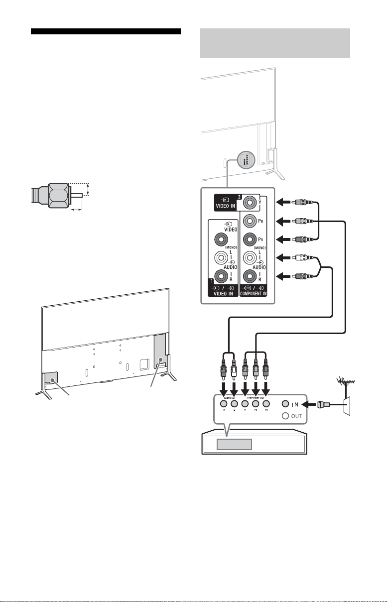
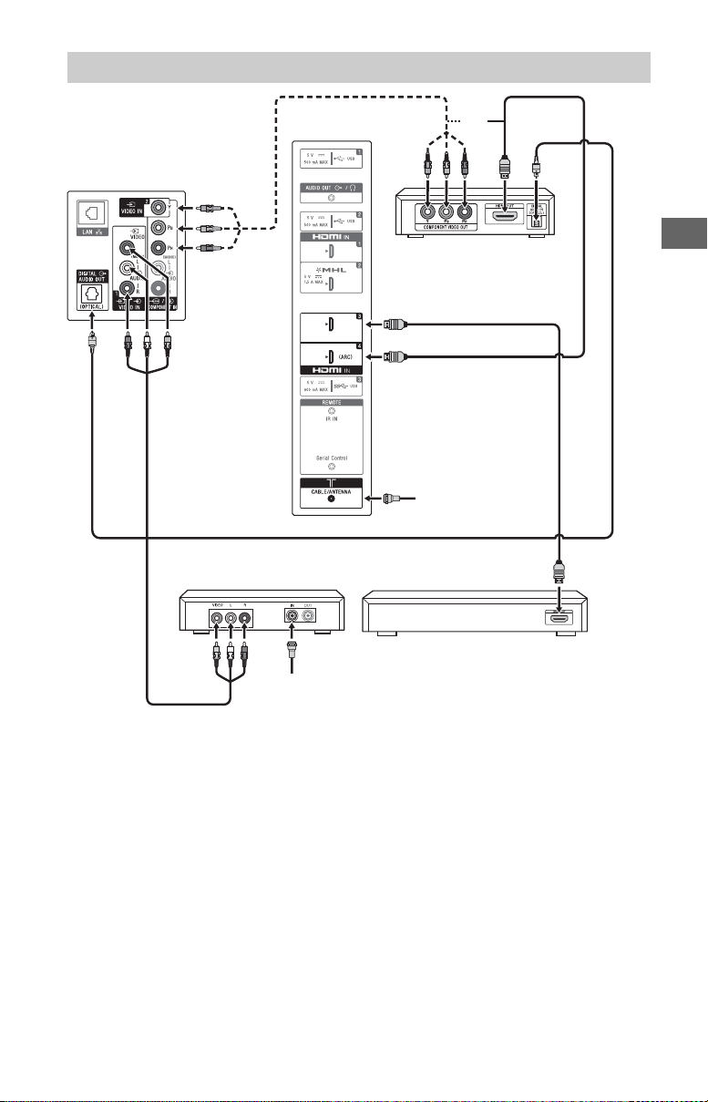
Connecting the TV
(Reference drawing for an F type plug)
1.5 mm max.
7 mm max.
Ter m ina l cover (lef t)
Terminal cover (right)
Set Top Box
For more information on connections, refer
to the Help Guide.
Note
• When connecting the cable to the Cable/
Antenna, input finger tighten only, over
tightening the connection can damage the TV.
• For the FMP-X1, connect it to the HDMI IN 2 jack
only (The av
• To select an input device connected to the TV,
pr
ess INPUT.
Recommendation for an F type plug
Projection of the inner wire from the
connection part must be less than 1.5 mm.
To attach the terminal cover
After connecting cables, attach the terminal
cover.
ailability depends on region).
Showing a Set Top Box with COMPONENT connection
US
16

Connecting MHL Device
Use authorized MHL CABLE
with MHL logo (not supplied)
MHL device
The TV simultaneously charges the MHL-compatible connected device while playing photo/
music/video files. You can use the TV remote control to control the connected MHLcompatible device.
Note
• If [Charge MHL during power off] is set to [On], you can continue charging the MHL-compatible device
even when the TV is in standby mode.
• Use authorized MHL 3 CABLE with MHL logo for 4K smartphone or mobile devices.
US
US
17
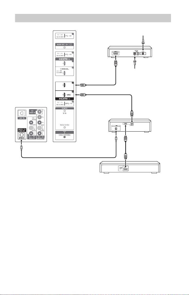
Showing HD BRAVIA® Sync™ Basic Connection
*1Side Panel
*
1
Blu-ray Disc
HD Cable Box or
HD Satellite Receiver
*
1
A/V Receiver
SAT (Dish)
Cable/Antenna
*
2
Optical Connection
*
1
Rear of TV
*1Signifies a BRAVIA Sync capable device.
*2The optical connection is only needed for A/V receivers that do not support ARC (Audio
Return Channel).
Set the speaker settings to audio out, press HOME, then select [Settings] [Sound]
[Speakers] [Audio system].
Set the HDMI CEC settings on the TV and AV receiver to allow for system audio control for
ARC connections.
US
18
Showing HD Basic Connection with Home Theater System
Cable/Antenna
Blu-ray Disc/DVD
SD Cable Box or
SD Satellite Receiver
Cable/SAT (Dish)
Home Theater System
*Optical Connection
Rear of TV
Side Panel
or
US
* The optical connection is only needed for home theater system that do not support ARC
(Audio Return Channel) when connecting with HDMI.
Set the speaker settings to audio out, press HOME, then select [Settings] [Sound]
[Speakers] [Audio system].
Set the HDMI CEC settings on the TV and AV receiver to allow for system audio control for
ARC connections.
US
19
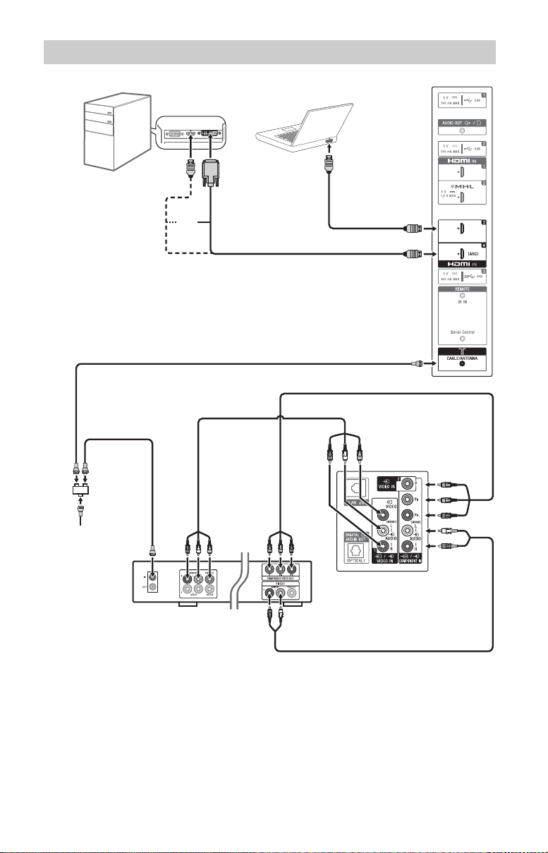
Showing PC Connection with SD VCR/DVD
Rear of TV
PC
DVD
VCR
Splitter
Cable/Antenna
VCR/DVD
Combo
*DVI
or
Side Panel
Notebook PC
* DVI does not support audio signals. Connect the audio output of the PC to the PC speakers
or an A/V receiver to listen to sound from the PC.
20
US
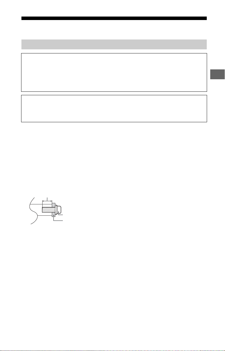
Installing the TV to the Wall
Wall-Mount Bracket
Screw (M6)
8 mm - 12 mm
Using the supplied Wall-Mount Bracket
To C ustomers
Sufficient expertise is required for installing this product. Be sure to subcontract the
installation to Sony dealers or licensed contractors and pay special attention to safety
during the installation. Sony is not liable for any damages or injury caused by mishandling
or improper installation, or installing any other than the specified product. Your Statutory
Rights (if any) are not affected.
To Sony Dealers and Contractors
Sufficient expertise is required for installing this product. Be sure to read this instruction
manual thoroughly to do the installation work safely. Sony is not liable for any damages or
injury caused by mishandling or improper installation.
Your TV can be mounted on a wall using a Wall-Mount Bracket (supplied with the TV) out of
the box as packaged.
Prepare the TV for the Wall-Mount Bracket before making cable connections.
For product protection and safety reasons, Sony strongly recommends that installation of
your TV on the wall be performed by qualified professionals. Do not attempt to install it
yourself.
Follow the instruction guide provided with the Wall-Mount Bracket for your model. Sufficient
expertise is required in installing this TV, especially to determine the strength of the wall for
withstanding the TV’s weight.
The length of the screw for Wall-Mount Bracket differs depending on the Wall-Mount Bracket
thickness. Please see below illustration.
US
Note
• Read the supplied Safety Booklet for additional safety information.
• See page 3 (Safety Information) and page 6 (Precautions) on WALL-MOUNT BRACKET before carrying out
Wall-Mount Bracket installation.
• When attaching the Table-Top Stand again, be sure t
original holes on the rear of the TV.
o fasten the screws (previously removed) to the
US
21
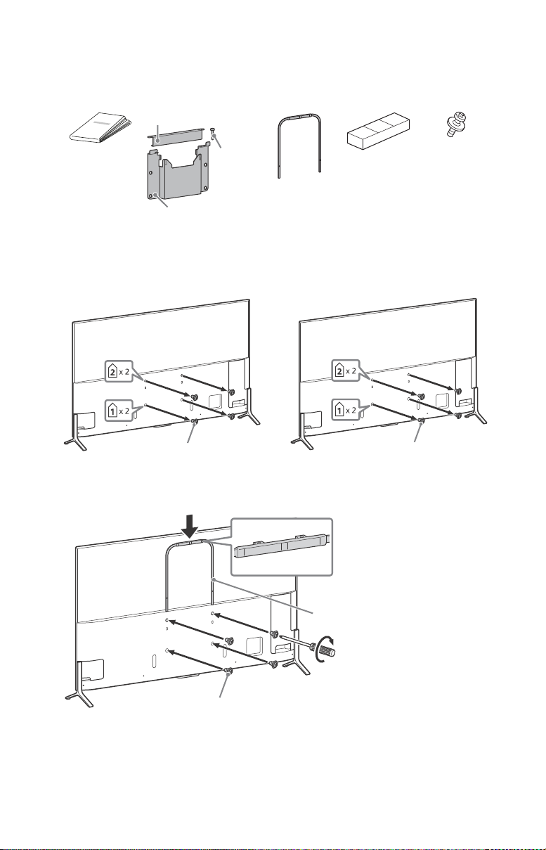
1 Prepare necessary items.
A Paper
Tem pl ate
H Wall-Mount
Bracket
J U-shaped Bar K Cushion
Lock plate
Lock pin
Wall-Mount Bracket
L M6 × 20
XBR-75X910C
(4)
M6 × 12
XBR-75X900C
XBR-65/55X900C
M6 × 16
M6 × 20 L
U-shaped Bar J
1.5 N∙m/1,5 N∙m
{15 kgf∙cm}
XBR-75X900C
Wall-Mount Bracket accessories (supplied)
Screws for Wall-Mount Bracket (8 mm in diameter, not supplied) (4)
2 Remove the screws from the rear of the TV.
3 Attach the U-shaped Bar J (supplied with the TV) to the rear of the TV.
US
22
 Loading...