

Page 1

DIGITAL VIDEOCASSETTE RECORDER
DVW-A500/1
DVW-A500P/1
DVW-500/1
DVW-500P/1
CONTROL PANEL
BKDW-515
ANALOG COMPOSITE DECODER BOARD
BKDW-505/506
AUDIO PROGRAM PLAY BOARD
BKDW-507
PARALLEL (50P) INTERFACE KIT
BKDW-509
CONTROL PANEL
BKDW-514
OPERATION MANUAL
1st Edition (Revised 3)
Serial No. 50001 and Higher (DVW-A500/1)
Serial No. 50001 and Higher (DVW-A500P/1)
Serial No. 50001 and Higher (DVW-500/1)
[English]
Serial No. 50001 and Higher (DVW-500P/1)
Serial No. 10001 and Higher (BKDW-515)
Page 2

WARNING
To prevent fire or shock hazard, do not
expose the unit to rain or moisture.
To avoid electrical shock, do not open the
cobinet. Refer servicing to qualified
personnel only.
For the customers in the United Kingdom
WARNING
THIS APPARATUS MUST BE EARTHED
IMPORTANT
The wires in this mains lead are coloured in accordance
with the following code:
Green-and-yellow: Earth
Blue: Neutral
Brown: Live
As the colours of the wires in the mains lead of this
apparatus may not correspond with the coloured markings
identifying the terminals in your plug, proceed as follows:
The wire which is coloured green-and-yellow must be
connected to the terminal in the plug which is marked by
the letter E or by the safety earth symbol Y or coloured
green or green-and-yellow.
The wire which is coloured blue must be connected to the
terminal which is marked with the letter N or coloured
black.
The wire which is coloured brown must be connected to
the terminal which is marked with the letter L or coloured
red.
For the customers in U.S.A.
This symbol is intended to alert the
user to the presence of uninsulated
“dangerous voltage” within the
product’s enclosure that may be of
sufficient magnitude to constitute a risk
of electric shock to persons.
This symbol is intended to alert the
user to the presence of important
operating and maintenance (servicing)
instructions in the literature
accompanying the appliance.
For the customers in Europe (For BKDW-515)
This product with the CE marking complies with the EMC
Directive (89/336/EEC) issued by the Commission of the
European Community.
Compliance with this directive implies conformity to the
following European standards:
• EN55103-1: Electromagnetic Interference (Emission)
• EN55103-2: Electromagnetic Susceptibility (Immunity)
This product is intended for use in the following
Electromagnetic Environment:
E4 (controlled EMC environment, ex. TV studio).
This equipment has been tested and found to comply with
the limits for a Class A digital device, pursuant to Part 15 of
the FCC Rules. These limits are designed to provide
reasonable protection against harmful interference when the
equipment is operated in a commercial environment. This
equipment generates, uses, and can radiate radio frequency
energy and, if not installed and used in accordance with the
instruction manual, may cause harmful interference to radio
communications. Operation of this equipment in a
residential area is likely to cause harmful interference in
which case the user will be required to correct the
interference at his or her own expense.
You are cautioned that any changes or modifications not
expressly approved in this manual could void your authority
to operate this equipment.
The shielded interface cable recommended in this manual
must be used with this equipment in order to comply with
the limits for a digital device pursuant to Subpart B of Part
15 of FCC Rules.
WARNING: Using this unit at a voltage other than 120 V
may require the use of a different line cord or attachment
plug, or both. To reduce the risk of fire or electric shock,
refer servicing to qualified service personnel.
Page 3

Table of Contents
Table of Contents
Chapter 1
Overview
Chapter 2
Locations and Functions
of Parts and Controls
Chapter 3
Setting Up the VTR
1-1 Features ........................................................................................... 1-1
1-1-1 Features of the DVW-A500/1, A500P/1, 500/1 and 500P/1.. 1-1
1-1-2 Features of the BKDW-515 ................................................... 1-3
1-2 Optional Accessories ...................................................................... 1-5
2-1 Control Panel .................................................................................. 2-1
2-1-1 Upper Control Panel............................................................... 2-2
2-1-2 Lower Control Panel (Menu Operations Section).................. 2-5
2-1-3 Lower Control Panel (Editing Operations Section) ............... 2-7
2-1-4 Lower Control Panel (Tape Transport Section)..................... 2-9
2-1-5 Lower Control Panel (Search Operations Section).............. 2-11
2-2 System Set-Up Panel .................................................................... 2-13
2-3 Connector Panel ........................................................................... 2-14
3-1 Connecting External Equipment .................................................. 3-1
3-1-1 Making Digital Connections .................................................. 3-1
3-1-2 Making Analog Connections ................................................. 3-2
3-2 Reference Signals for Video Output and Servo System.............. 3-3
3-2-1 External Sync Signal for the Internal Reference Video Signal
Generator................................................................................ 3-3
3-2-2 Reference Signal for the Servo System.................................. 3-4
3-2-3 Reference Signals Connections.............................................. 3-5
3-3 Handling Cassettes ......................................................................... 3-7
3-3-1 Recommended Cassettes........................................................ 3-7
3-3-2 Inserting and Ejecting Cassettes ............................................ 3-7
3-3-3 Preventing Accidental Erasure............................................... 3-8
Chapter 4
Menu Settings
(Continued)
4-1 Registering and Storing Menu Settings........................................ 4-1
4-1-1 Menu Configuration............................................................... 4-1
4-1-2 Changing Menu Settings........................................................ 4-2
4-1-3 Registering Items to the PF1/2 Menus................................... 4-3
4-1-4 VTR Memory Bank Function ................................................ 4-4
4-1-5 IC Memory Card Function..................................................... 4-6
4-1-6 Adding Titles to the Data..................................................... 4-11
4-1-7 Details on VTR Memory Bank and IC Memory Card
Functions.............................................................................. 4-12
4-1-8 IC Memory Card Data Compatibility Among
the DVW-A500/1 and DVW-500/1 Series VTRs................ 4-12
4-2 HOME Menu ................................................................................ 4-13
4-2-1 Setting the Preread Function (PRE READ) ......................... 4-14
4-2-2 Simultaneous Playback During Recording (CONFI)........... 4-14
4-2-3 Selecting the Edit Mode and Edit Channel
(ASSEMBLE to INS CUE).................................................. 4-14
4-2-4 Setting Record Inhibit Mode (REC INH) ............................ 4-15
4-2-5 Selecting the Monitor Mode (PB/EE).................................. 4-15
4-2-6 Outputting Still-Pictures (FREEZE) .................................... 4-15
4-2-7 Selecting the Capstan Servo Lock Mode (CAP LOCK)...... 4-16
Table of Contents 1
Page 4

Table of Contents
Table of Contents
Chapter 4
Menu Settings
4-2-8 Setting the Preroll Time (P-ROLL TIME)........................... 4-16
4-2-9 Selecting DMC Playback (DMC) ........................................ 4-17
4-2-10 Selecting Program Playback (P.PLAY).............................. 4-17
4-2-11 Recalling Edit Points (LAST EDIT)................................... 4-17
4-3 TC Menu ....................................................................................... 4-18
4-3-1 Setting the Time Data (TIMER SEL/RESET/SET/HOLD) 4-19
4-3-2 Setting the Time Code Reader (TC SEL) ............................ 4-21
4-3-3 Setting the Time Code Generator
(TCG SOURCE/MODE) ..................................................... 4-21
4-3-4 Selecting the Time Code Running Mode (RUN MODE).... 4-22
4-3-5 Selecting the Drop Frame Mode (DF/NDF) (DVW-A500/1 and
500/1 only) ........................................................................... 4-22
4-3-6 Recording VITC (VITC)...................................................... 4-23
4-3-7 Selecting CTL Display Mode (TAPE TIMER) ................... 4-23
4-3-8 ID Preset (ID PRESET) ....................................................... 4-23
4-3-9 Superimposition of Character Information
(CHARA SUPER/H-POS/V-POS) ...................................... 4-23
4-3-10 Setting the VITC Insertion Line (VITC POS-1/POS-2)..... 4-26
4-4 CUE Menu .................................................................................... 4-27
4-4-1 Selecting a Multi-Cue Mode................................................ 4-28
4-4-2 Registering Cue Points......................................................... 4-28
4-4-3 Erasing Cue Point Data........................................................ 4-30
4-4-4 Prerolling to a Cue Point...................................................... 4-31
4-4-5 Changing a Cue Point Into an Edit Point............................. 4-32
4-4-6 Backspace Editing................................................................ 4-32
4-5 PF1 Menu (Factory Settings)....................................................... 4-33
4-5-1 Selecting the Input Video Signal
(VIDEO IN) ......................................................................... 4-34
4-5-2 Selecting the Reference Signal
(OUT REF) .......................................................................... 4-34
4-5-3 Switching the Control of the Digital Video Processor
(PROC CONTRL)................................................................ 4-34
4-5-4 Adjusting the Output Video Signal
(VIDEO GAIN to SYSTEM SC)......................................... 4-34
4-6 PF2 Menu (Factory Settings)....................................................... 4-36
4-6-1 Selecting the Audio Input Signal
(A-IN ALL to A-IN CH4).................................................... 4-37
4-6-2 Setting the Dolby NR System
(DOLBY NR) (DVW-A500/1 Series Only) ........................ 4-37
4-6-3 Setting Emphasis (EMPHASIS) .......................................... 4-37
4-6-4 Selecting the Monitor Output Signal
(MON-L SEL/MON-R SEL) ............................................... 4-37
4-7 SET UP Menu ............................................................................... 4-38
4-7-1 VTR SETUP Menu .............................................................. 4-40
4-7-2 PANEL SETUP Menu ......................................................... 4-42
2 Table of Contents
Page 5

Table of Contents
Chapter 5
Recording/Playback
Chapter 6
Editing
5-1 Preparing for Recording................................................................ 5-1
5-1-1 Setting Switches and Menus .................................................. 5-1
5-1-2 Selecting Audio Signals......................................................... 5-2
5-1-3 Adjusting the Audio Recording Level ................................... 5-3
5-1-4 Monitoring Simultaneous Playback of Video and Audio Signals
Being Recorded.................................................................... 5-4
5-1-5 Recording Analog Audio ....................................................... 5-4
5-2 Recording ........................................................................................ 5-5
5-3 Preparing for Playback.................................................................. 5-6
5-3-1 Setting Switches and Menus .................................................. 5-6
5-3-2 Adjusting the Audio Playback Level ..................................... 5-6
5-4 Playback .......................................................................................... 5-7
5-4-1 Normal-Speed Playback......................................................... 5-7
5-4-2 Variable Speed Playback in Jog/Shuttle/Variable Modes...... 5-8
5-4-3 Capstan Override Playback.................................................. 5-10
5-4-4 DMC Playback..................................................................... 5-10
5-4-5 Program Playback ................................................................ 5-13
6-1 Basic Automatic Editing ................................................................ 6-1
6-1-1 Overview of Automatic Editing............................................. 6-1
6-1-2 Setting Switches and Menus .................................................. 6-2
6-1-3 Selecting the Edit Mode......................................................... 6-3
6-1-4 Setting Edit Points.................................................................. 6-3
6-1-5 Confirming Edit Points .......................................................... 6-7
6-1-6 Cuing Up and Prerolling ........................................................ 6-7
6-1-7 Previewing ............................................................................. 6-8
6-1-8 Modifying Edit Points............................................................ 6-9
6-1-9 Performing Automatic Editing............................................. 6-11
6-2 Advanced Automatic Editing ...................................................... 6-14
6-2-1 Performing DMC Editing..................................................... 6-14
6-2-2 Performing Quick Editing.................................................... 6-16
6-2-3 Performing Consecutive Editing.......................................... 6-17
6-2-4 Performing Preread Editing ................................................. 6-18
6-3 Manual Editing ............................................................................. 6-19
Chapter 7
Maintenance
7-1 Head Cleaning ................................................................................ 7-1
7-2 Moisture Condensation.................................................................. 7-2
Table of Contents 3
Page 6

Table of Contents
Table of Contents
Appendix
Specifications......................................................................................... A-1
Glossary ................................................................................................. A-5
Menu List .............................................................................................. A-7
Items Related to the Hours Meter (Hs) ........................................... A-7
Items Related to VTR Operations (000s) ........................................ A-8
Items Related to Operation Panels (100s) ..................................... A-10
Items Related to Remote Interface (200s)..................................... A-14
Items Related to Editing (300s)..................................................... A-15
Items Related to Prerolling (400s)................................................. A-19
Items Related to Recording Protection (500s) .............................. A-20
Items Related to the Time Code Generator (600s)........................ A-21
Items Related to the Video Control (700s).................................... A-24
Items Related to the Audio Control (800s) ................................... A-31
Items Related to Digital Process (900s) ........................................ A-34
Items Set by Switches on Models DVW-A500, A500P, 500,
and 500P (Ks)...................................................................... A-37
Index ........................................................................................................I-1
Function Button List (Factory Settings)................................. Last page
4 Table of Contents
Page 7

1-1 Features
Chapter 1 Overview
1-1-1 Features of the DVW-A500/1, A500P/1, 500/1 and 500P/1
The DVW-A500/1, A500P/1, 500/1, and 500P/1
Digital Videocassette Recorders adopt the Digital
Betacam format, and are differentiated as follows:
•The DVW-A500/1 and DVW-A500P/1 are capable of
playing back analog Betacam and Betacam SP format
cassette tapes.
•The DVW-500/1 and DVW-500P/1 are not
compatible with either the analog Betacam or
Betacam SP formats.
The DVW-A500/1 and 500/1 can be used in the NTSC
color system while the DVW-A500P/1 and 500P/1 can
be used in the PAL color system, though they both
adopt a component format.
Digital Betacam Format
The DVW-A500/1 series and DVW-500/1 series adopt
the newly developed Digital Betacam format as an
extension of the Betacam/Betacam SP format. The
Digital Betacam format makes the most of the
available recording area to achieve high-quality digital
recording, while maintaining analog Betacam tape
playback compatibility. The following have been
developed for this purpose:
•Coefficient recording system
•Powerful error correction system
•High-quality precision heads and drum with DT
(Dynamic Tracking) heads
•New auto tracking system
Together, these allow 120 minutes or more of
recording time on half-inch Digital Betacam (L-size)
cassettes the same size as those for conventional
Betacam and Betacam SP.
Overview of digial signal processing
Digital video signal processing is based on the 4:2:2
component digital D-1 format and CCIR 601 standard
quantization. In addition, the data rate is compressed
with the coefficient recording system. Digital audio
signals are processed in full bits conforming to the
AES/EBU format.
®
analog component signals and composite signals (with
the BKDW-505/506) are digitized into CCIR 601
standard parallel data.
Audio data from the AES/EBU digital interface or A/D
converted data from analog input can be selected for
recording.
Bit rate reduction encoder
Video data are suppressed to about half by a newly
developed coefficient recording system, whose key
processes include field shuffling, blocking, DCT
(Discrete Cosine Transform), quantizing, and variable
length coding.
ECC encoder
The outer ECC (Error Correction Code) is added to the
compressed video and audio data, followed by the
inner ECC, ID data, and sync data. The ReedSolomon code is employed in this error correction
system.
Channel coding
Video and audio data with the ECC added are recorded
in the form of serial data. The Digital Betacam format
adopts a scrambled NRZI channel coding system that
is superior in off-track and noise characteristics.
Playback signal processing
The playback digital data are equalized by auto EQ
circuits and error-corrected by powerful inner and
outer ECC, which can correct most data disturbed by
noise and dropouts in the reproduced signal. Data that
cannot be corrected further are compensated by error
concealment circuits.
Output interface
Component video data are converted into serial data
and multiplexed with audio data, then output in the
serial digital interface format.
For analog output, component video data are D/A
converted into an analog component signal, while they
are encoded into composite digital, then D/A
converted into analog composite signal.
For audio outputs, the AES/EBU digital interface and
D/A converted analog audio are available.
Chapter 1 Overview
Input interface
The component serial digital interface, conforming to
SMPTE 259M/EBU T.3267/CCIR 656-III standards,
handles component video signals and 4-channel digital
audio signals with a single BNC coaxial cable. Both
Chapter 1 Overview 1-1
Page 8

1-1 Features
Chapter 1 Overview
Advanced Recording and Playback
Functions
High-quality digital recording
The DVW-A500/1 series and DVW-500/1 series adopt
component digital video and a four-channel, 20-bit
digital audio recording system using an AES/EBU
format with a wide dynamic range. A digital signal
processing system that includes an advanced error
correction and concealment system that are unique to
digital Betacam provides superb video and audio
quality, while the adjusting and setting of a built-in
digital video processor ensures the output of precise
and stable video signals.
Playback compatibility with analog Betacam
and Betacam SP (DVW-A500/1 series only)
The DVW-A500/1 series provide playback capability
with tapes recorded on the Betacam SP VTRs, so that
Betacam users can upgrade to a digital environment
while enjoying continued access to the enormous
analog Betacam archives.
Noiseless playback with DT heads
Using the playback DT heads, you can perform
noiseless playback at 54 speeds ranging from –1 to +3
times normal speed, including still-picture playback.
Noiseless playback is also supported in the case of
both digital and analog Betacam playback.
Video and audio confidence heads
Video and audio confidence heads enable you to play
back video and audio signals on channels 1 to 4 while
recording, to check the quality of the recording.
Internal time code generator and reader
The internal time code generator allows you to record
LTC/VITC time codes and user bits together with
video and audio signals. Time codes and user bits are
read by the internal time code reader during playback.
Computer servo system
Computer-controlled servo motors provide direct drive
for the drum, capstan, and two reels, enabling quick
and accurate tape access.
Capstan override function
You can adjust the playback speed by ±15% to ensure
synchronization between, for example, two VTRs
playing back the same program.
Independent level controls
The recording and playback levels of each of the four
audio channels can be set indepenently during
monitoring of audio level meters.
Features for Ease of Operation
Compact, lightweight, low power consumption
The VTR is small and light enough to be used in
outside broadcast vans or in EFP (Electronic Field
Production) assignments.
Remote control operation
The VTR has a serial RS-422A 9-pin connector to
allow control of the VTR by an external control unit
through RS-422A communications.
The VTR also comes with 9-pin REMOTE1-IN(9P)
and OUT(9P) connectors to support bridge connection
of multiple DVW-A500/1 or DVW-500/1 series units
or other VTRs equipped with 9-pin remote connectors
for simultaneous operations.
Furthermore, by using the optional BKDW-509
Parallel (50-pin) Interface Kit, you can control the
VTR from an external control unit with a parallel
interface.
Digital hours meter
Three different hour displays and one cycle count
display are supported, showing total elapsed time since
the VTR was turned on, total drum revolution time,
total tape running time and total number of threadings
and unthreadings.
Self-diagnosis
When enabled through the maintenance menu, any
malfunction causes the VTR to perform self-diagnosis,
after which it displays the relevant error code in the
display.
Easy-to-maintain plug-in boards
The VTR uses plug-in circuit boards to simplify
servicing and inspection.
Mountable in standard 19-inch rack
The unit can be mounted in an EIA-standard 19-inch
rack.
For rack mounting, refer to the Installation Manual.
1-2 Chapter 1 Overview
Page 9

1-1-2 Features of the BKDW-515
The BKDW-515 Control Panel provides six menu
screens corresponding to the six operation modes to
allow fast and easy adjustment of necessary settings, as
well as the ability to store menu settings to a memory
card for later recall.
Menu-driven operations for a variety of
purposes
Six types of menus appear on the BKDW-515’s 90 ×
72 mm (35/8 inches × 27/8 inches) display, and are set
using the 10 /function buttons to the left and at the
bottom of the display.
•Use the PANEL SETUP menu to set control panel
operations, such as the keyboard sound output.
Chapter 1 Overview
MAINTENANCE menu
Use this menu to access the maintenance functions in
conjunction with a video monitor.
For details, refer to the Installation and Maintenance
Manual.
A full complement of storage/recall
functions
These functions allow you to store and recall menu
settings in either the VTR’s internal memory banks or
IC memory cards by title.
HOME menu
Use this menu to make the basic settings for recording,
playback, and editing operations, and to select
channels to be edited during insert editing.
TC menu
Use this menu to make time code settings.
CUE menu
Use this menu to set up to 100 cue points. In page
mode, 10 cue points per page can be set on a total of
10 pages.
PF1/PF2 (Personal Function) menus
Use these menus to register up to 40 of the most
frequently used items from the other menus (up to ten
items each can be registered to PF1, ALT+PF1, PF2
and ALT+PF2). You can display the registerable items
by pressing the [F4] (PF1&2 ASSIGN) button in the
SET UP menu.
SET UP menu
•Use the VTR BANK menu to memorize menu
settings of up to 8 pages.
•Use the MEMORY CARD menu to store current
settings of the VTR and up to 8 pages of the contents
of the VTR memory bank to an IC memory card.
•Use the scrollable PF1&2 ASSIGN menu to display
the items that can be registered in the PF1/PF2
menus, and to select and register the most frequently
used menu items.
•Use the scrollable VTR SETUP menu to display the
items necessary for making initial settings, and to
directly change settings without registering them to
the function buttons for each menu.
VTR memory banks
These memory banks allow you to store up to eight
pages of VTR settings in addition to the current VTR
settings. Factory settings are also stored here, allowing
the VTR to be reset to these values at any time.
IC memory cards
Each IC memory card can hold the current VTR
settings as well as up to eight pages of settings. A
single IC memory card thus allows you to store and
recall the entire contents of the VTR memory banks.
Title function
This function allows you to add titles when storing data
to the VTR memory bank or IC memory card, thus
facilitating data retrieval and management.
A full range of editing functions
You can connect two DVW-A500/1 or DVW-500/1
series units to enable automatic or manual editing in
either assemble or insert mode. The VTR also features
a full range of editing functions, including preview,
review, preroll, and the setting or changing of edit
points.
Quick access to edit points
The following methods are provided for the setting of
edit points:
•Multi-cuing for up to 100 edit points
•Search dial with shuttle and jog functions
•Direct input through numeric buttons
Chapter 1 Overview 1-3
Page 10

1-1 Features
Chapter 1 Overview
DMC (Dynamic Motion Control) editing
®
Using the DT
(Dynamic Tracking ) heads, you can
play back a section of an edit at speeds between –1 and
+3 times normal speed, and store the speed variation in
memory for later use in automatic editing.
Split editing
In insert mode, you can set audio and video edit points
separately.
Preread editing
You can perform preread editing using video or digital
audio signals recorded on the tape as the edit source
for insert editing.
A variety of audio editing modes
You can select cut-in editing, cross-fade editing, and
fade in/out editing for the audio signals.
Display of duration between edit points
After edit point data have been set, you can display the
duration between any two IN, OUT, AUDIO IN, or
AUDIO OUT points by simultaneously pressing two
buttons corresponding to those edit points.
Digital time counter
The time counter display shows CTL and time codes
1)
(LTC/VITC
), or user bits data to enable the precise
setting of edit points.
..........................................................................................................................................................................................................
1) LTC (Longitudinal Time Code)
Time code recorded on a longitudinal track
VITC (Vertical Interval Time Code)
Time code recorded on a video track during
the vertical blanking interval
1-4 Chapter 1 Overview
Page 11

1-2 Optional Accessories
The following accessories can be used with the DVWA500/1 series and DVW-500/1 series:
BKDW-505 (for NTSC video format)/BKDW506 (for PAL video format) Analog Composite
Decoder Board
Converts in-coming analog composite video signals to
digital signals. Allows bridge connection with other
components.
BKDW-507 Audio Program Play Board
Enables the output of audio signals that retain their
original pitch during program playback. Also
stabilizes pictures during program playback.
BKDW-509 Parallel (50-pin) Interface Kit
Allows you to remotely control the DVW-A500/1
series or DVW-500/1 series from an external control
unit with a parallel interface.
BKDW-514 Control Panel
When attached in place of the BKDW-515, this
control panel makes the VTR equivalent to the DVWA500 series or DVW-500 series in function and
capability.
Note
The BKDW-515 and the control panel of the DVWA500/1 or DVW-500/1 series cannot be installed in
the BKDW-511 Control Panel Case.
References
In addition to this Operation Manual, the following
manuals are available:
•Installation and Maintenance Manual (supplied with
the DVW-A500/1 series, DVW-500/1 series or the
BKDW-515)
Provides information necessary for users to maintain
the control panel.
•Installation Manual (supplied with the DVW-A500/1
series or DVW-500/1 series)
Provides information necessary to install the VTR
and its peripherals.
•Manitenance Manual Part 1 (supplied with the DVWA500/1 series or DVW-500/1 series)
Provides information necessary for users to maintain
the VTR.
•Maintenance Manual Part 2 (available on request)
Provides additional information to fully maintain the
DVW-A500/1 series, DVW-500/1 series and the
BKDW-515. Contains details on electrical
adjustments, circuit diagrams, and other items.
Chapter 1 Overview
Chapter 1 Overview 1-5
Page 12

Chapter 1 Overview
1-1 Features
1-6 Chapter 1 Overview
Page 13

2-1 Control Panel
Chapter 2 Locations and Functions of Parts and Controls
The control panel consists of the following sections:
•Upper control panel
•Lower control panel: menu operations section, IC
Upper control panel
Lower control panel
memory card insertion slot, editing operations
section, tape transport section and search operations
section
Chapter 2 Locations and Functions of Parts and Controls
Menu operations section
Editing operations section
IC memory card
insertion slot
Control panel
Search operations section
Tape transport section
Chapter 2 Locations and Functions of Parts and Controls 2-1
Page 14

2-1 Control Panel
2-1-1 Upper Control Panel
1DISPLAY FULL/FINE button
2PHONES jack
Chapter 2 Locations and Functions of Parts and Controls
3POWER switch
4PHONES level control
5 PB level
controls
6REC level controls
7Audio level meters
8Indicator window
9MONITOR SELECT button
!ºINPUT SELECT button
!¡AUDIO INPUT/MONITOR SELECT buttons
!™VIDEO INPUT SELECT buttons
!£REMOTE buttons and RS-232C indicator
Upper control panel
1 DISPLAY FULL/FINE button
Changes the display range of the audio level meters.
FULL: Display range is –60 to 0 dB (peak level = 0
dB) or –40 to +20 dB (peak level = +20 dB).
Use 806. LEVEL METER SCALE in the VTR
SETUP menu to select the range.
FINE: Displays the audio level in 0.25 dB
increments. The center LED lights up in each
meter as a signal level reference. When the level
exceeds the maximum display value, the top LED
lights up. When the level falls below the
minimum display value, the bottom LED lights
up.
2 PHONES jack
Connects stereo headphones with 8 Ω impedance for
audio monitoring during recording, playback, and
editing. Adjust the headphone output level with the
PHONES level control.
3 POWER switch
Turns on the power. When the power is turned on, the
audio level meters and menu display in the lower
control panel light up.
2-2 Chapter 2 Locations and Functions of Parts and Controls
Page 15

4 PHONES level control
Adjusts the output level to the PHONES jack.
You can enable this control to simultaneously adjust
the output level to the MONITOR OUTPUT
connectors on the connector panel.
For details, refer to “5-1-2 Selecting Audio Signals” on
page 5-2.
5 PB (playback) level controls
Adjust the level of the audio output for channels 1 to 4
and the cue channel.
Pull out the controls during playback to adjust the
audio output for each channel. Push in again for
factory-set levels (+4 dB output for a signal recorded
at a reference level of 0 dB). When pushed in, the
controls cannot adjust the audio output level.
6 REC (recording) level controls
Adjust the recording level for channels 1 to 4 and the
cue channel.
Pull out the controls to adjust the recording level for
1)
each channel in E-E mode
. Push in again for the
factory-set recording level (0 dB reference level for an
input of +4 dB). When pushed in, the controls cannot
adjust the recording level.
7 Audio level meters
Indicate the recording level in recording or E-E mode
or the playback level in playback or CONFI mode.
The display range can be changed by pressing the
DISPLAY FULL/FINE button. The reference level is
factory set at –20 dB, and the peak level at 0 dB.
8 Indicator window
The following indicators light up to indicate the VTR’s
status.
Indicators and corresponding VTR status
Indicator Status
DOLBY NR
(DVW-A500/1
series only)
KEY INHIBIT Lights up when the [F1] (KEYINH) button
CHANNEL
CONDITION
DIGITAL Lights up when a Digital Betacam
LTC Lights up when the VTR is recording LTC
VITC Lights up when the VTR is reading VITC
Lights up when the Dolby NR circuit is
activated.
in the PANEL SETUP menu is set to on.
Indicates the playback signal condition.
Green: Playback signal is good.
Yellow: Playback signal is less than
good, but still reproducible.
Red: Playback signal is poor. Head
cleaning or internal inspection is
necessary if the indicator lights up
continuously.
cassette is inserted, and turns off when
an analog Betacam cassette is inserted.
signals or reading LTC signals during
playback. Also lights up in E-E mode if
you press the REC button while the [F6]
(TCG SOURCE) button in the TC menu
set to ext, allowing you to verify that the
VTR is locked to an external time code.
signals during playback, or when the VTR
is in recording or E-E mode and the video
input signal contains VITC signals. Also
lights up when the [F10] (VITC) button in
the TC menu is set to on and the VITC
signals contained in the video signal are
normal.
9 MONITOR SELECT button
Selects the audio signal to be output at the MONITOR
OUTPUT L/R connector(s). Press to light the button
up, then press the AUDIO INPUT/MONITOR
SELECT button(s) to specify which channel(s) are to
be monitored at the MONITOR OUTPUT L or R
connector. If you specify more than one channel to the
same MONITOR OUTPUT connector, a mixed audio
signal is output from that connector. This specification
can also be done as a menu operation.
Chapter 2 Locations and Functions of Parts and Controls
For details, refer to “4-6-4 Selecting the Monitor Output
Signal (MON-L SEL/MON-R SEL)” on page 4-37.
..........................................................................................................................................................................................................
1) E-E mode
An abbreviation for Electric-to-Electric mode. In this
mode, video or audio input signals are passed and output
only through the VTR’s internal circuitry, and not
through the magnetic conversion system comprising tape
and heads.
Chapter 2 Locations and Functions of Parts and Controls 2-3
Page 16

2-1 Control Panel
!º INPUT SELECT button
Selects the audio input signal. Press to light the button
up, then press one of the AUDIO INPUT/MONITOR
SELECT buttons to select the type and the channel of
the audio signal.
SIF (CH-1 to CH-4): Selects signal input to the
Chapter 2 Locations and Functions of Parts and Controls
SERIAL V/A INPUT connector.
AES/EBU (CH-1 to CH-4): Selects signal input to
the AUDIO INPUT (AES/EBU) connectors.
ANALOG (CH-1 to CH-4): Selects signal input to
the ANALOG AUDIO INPUT connectors.
If you select the SERIAL V/A INPUT or AUDIO
INPUT (AES/EBU) connectors when there is no
incoming signal, the INPUT SELECT button flashes.
This specification can also be done as a menu
operation.
For details, refer to “4-6-1 Selecting the Audio Input Signal
(A-IN ALL to A-IN CH4)” on page 4-37.
!¡ AUDIO INPUT/MONITOR SELECT buttons
Select the audio input signal when the INPUT
SELECT button lights up, or the audio signal to be
monitored when the MONITOR SELECT button lights
up.
!£ REMOTE buttons and RS-232C indicator
Press these buttons to select external equipment to be
used to remotely control the VTR.
1(9P): Press to select the unit connected to the
REMOTE1-IN(9P)/OUT(9P) connectors. The
button lights up.
2(50P): Press to select the unit connected to the
REMOTE PARALLEL I/O(50P) connector (with
optional BKDW-509). The button lights up.
RS-232C indicator: Lights up when the VTR is
communicating with the external equipment
connected to the RS-232C connector.
Note
When the VTR is being controlled by external
equipment connected to the REMOTE1-IN(9P) or
REMOTE PARALLEL I/O(50P) connector, all tape
transport buttons and edit operation buttons are
disabled, except the STOP and EJECT buttons. You
may also specify the disabling or enabling of all
buttons by setting 006. LOCAL FUNCTION
ENABLE in the VTR SETUP menu.
!™ VIDEO INPUT SELECT buttons
Press one of the following buttons to select the video
input signal.
If you select a connector which has no incoming
signal, the button flashes.
SIF: Selects the serial digital video signal input to
the SERIAL V/A INPUT connector.
COMPONENT (Y-R, B): Selects the analog
component video signal input to the
COMPONENT VIDEO INPUT connectors.
COMPOSITE: Selects the analog composite video
signal input to the COMPOSITE VIDEO INPUT
connector.
Note
To input analog composite video signal, you must
install the optional BKDW-505 (for NTSC video
format)/BKDW-506 (for PAL video format) Analog
Composite Decoder Board.
2-4 Chapter 2 Locations and Functions of Parts and Controls
Page 17

2-1-2 Lower Control Panel (Menu Operations Section)
1Menu display
3MEMORY CARD indicator
2Menu buttons
4ACCESS button
Chapter 2 Locations and Functions of Parts and Controls
7ALT button
8MAINTENANCE switch
9ALARM indicator
5IC memory card insertion slot
6Function buttons
Lower control panel (menu operations section)
Chapter 2 Locations and Functions of Parts and Controls 2-5
Page 18

2-1 Control Panel
1 Menu display
Menus selected by pressing the menu buttons appear
here.
Each menu shows the functions assigned to each
function button ([F1] to [F10]) and information
necessary for making settings, such as time codes.
Chapter 2 Locations and Functions of Parts and Controls
2 Menu buttons
Press to activate the respective menu.
HOME button: Activates the HOME menu.
Settings for basic or editing operations are made
in the HOME menu.
TC button: Activates the TC (time code) menu. In
the TC menu, you can switch between LTC and
VITC and between DF and NDF (DVW-A500/1
and DVW-500/1 only), and make settings for time
code displays on an external monitor.
CUE button: Activates the CUE menu. In the CUE
menu, you can register 10 cue points per page for
a total of 100 cue points.
PF1 button: Activates the PF (Personal Function) 1
menu. In the PF1 menu, you can register
frequently used settings in other menus. Settings
for video input/output signals are factory set.
PF2 button: Activates the PF (Personal Function) 2
menu. In the PF2 menu, you can register
frequently used settings in other menus. Settings
for audio input/output signals are factory set.
SET UP button: Activates the SET UP menu. Use
the SET UP menu to restore settings to the VTR
memory banks or IC memory card, register
functions to the PF1/2 menus, and set items in the
VTR SETUP menu.
5 IC memory card insertion slot
Insert IC memory cards here. VTR settings can be
stored on cards and used to configure the VTR and
control panel at a later date, thus reducing the time
required for set up.
Press the button beside the insertion slot to eject the IC
memory card.
6 Function buttons
Activate the functions for the respective function
buttons in each menu.
7 ALT (alternative) button
Press to change the functions of the current menu.
Press again to return to the original functions.
8 MAINTENANCE switch
Activates the MAINTENANCE menu.
To operate this switch, push it in using the tip of a pen
or some other pointed object while holding down the
SFT button.
9 ALARM indicator
Lights up when the communication between the VTR
and the control panel is abnormal.
For details, refer to “Chapter 4 Menu Settings” on page 4-
1.
3 MEMORY CARD indicator
Lights up when the IC memory card is inserted.
4 ACCESS button
Press this button to directly activate the MEMORY
CARD menu. Flashes when the control panel is
accessing the IC memory card.
Note
Do not eject the IC memory card while the ACCESS
button lights up as this may damage the contents of the
memory card.
2-6 Chapter 2 Locations and Functions of Parts and Controls
Page 19

2-1-3 Lower Control Panel (Editing Operations Section)
!ºNumeric buttons and +/– buttons
!¡SFT button
!™RCL button
!£CLR button
!¢SET button
Chapter 2 Locations and Functions of Parts and Controls
!∞AUDIO IN/OUT buttons
!§IN/OUT buttons
!¶ENTRY button
!•Cursor control buttons
@£PREREAD indicator
@™PLAYER/RECORDER buttons
@¡REVIEW button
@ºAUTO EDIT button
!ªPREVIEW button
Lower control panel (editing operations section)
Chapter 2 Locations and Functions of Parts and Controls 2-7
Page 20

2-1 Control Panel
!º Numeric buttons and +/– buttons
Press to input time data or edit points data at the cursor
position in menu display. Press buttons 0 to 5 while
holding down the SFT button to input A to F
(hexadecimal figures) for user bits. Use the +/–
buttons to increase or decrease settings.
Chapter 2 Locations and Functions of Parts and Controls
!¡ SFT (shift) button
Press buttons 0 to 5 while holding down this button to
input A to F (hexadecimal figures) for user bits.
Use also in combination with other buttons to perform
other operations.
!™ RCL (recall) button
Press to call up a previously entered value.
!£ CLR (clear) button
Press to clear a value.
!¢ SET button
Press to enter a value.
!∞ AUDIO IN/OUT buttons
Press to set AUDIO IN and OUT points during insert
mode. Press either AUDIO IN or OUT button while
holding down the ENTRY button to set an audio edit
point.
!§ IN/OUT buttons
Press to set an IN or OUT point during editing. Press
either button while holding down the ENTRY button
to set an edit point.
!¶ ENTRY button
Press to enter an edit or cue point.
While holding down this button, press either the
AUDIO IN or OUT button, or the IN or OUT button.
!• Cursor control buttons
Press to move the cursor in the menu display. Move
the cursor as required to enter a value using the
numeric buttons, or to change a menu setting.
!ª PREVIEW button
Press to view the results of an edit on a monitor
connected to the recorder VTR without actually
recording the edit. During previewing, the tape moves,
but actual editing is not carried out. If no IN point has
been set when you press this button, the current tape
position is set as the IN point at the start of the
preview.
@º AUTO EDIT (automatic editing) button
Press to do automatic editing after you have set the
edit points. If no IN point has been set when you press
this button, the current tape position is set as the IN
point at the start of automatic editing.
@¡ REVIEW button
Press to review results of an edit (a section between
one IN point and one OUT point) on a monitor
connected to the recorder.
@™ PLAYER/RECORDER buttons
Select which VTR is to be controlled by this VTR’s
control panel during editing when this VTR is used as
a recorder and an external VTR connected to the
REMOTE1-IN(9P)/OUT(9P) connectors as a player.
PLAYER: The tape transport buttons and editing
operation buttons on the control panel control the
external player VTR.
RECORDER: The tape transport buttons and
editing operation buttons on the control panel
control the recorder VTR (this VTR).
The PLAYER/RECORDER buttons have no effect
when using this VTR alone.
@£ PREREAD indicator
Lights up during preread mode.
For details on prereading, refer to “6-2-4 Performing
Preread Editing” on page 6-18.
2-8 Chapter 2 Locations and Functions of Parts and Controls
Page 21

2-1-4 Lower Control Panel (Tape Transport Section)
@¢PREROLL button
@ªSTOP button
@∞EJECT button
@§STANDBY button
@¶EDIT button
Chapter 2 Locations and Functions of Parts and Controls
@•SERVO indicator
#ºPLAY button
#¡REC button
#™REC INHIBIT indicator
Lower control panel (tape transport section)
@¢ PREROLL button
Press to position the tape to the preroll point (a
position factory set to five seconds before the IN
point).
Press this button while holding down the IN, OUT,
AUDIO IN or AUDIO OUT button to cue up the tape
at the edit point of the respective button.
For details on changing the preroll time, refer to “4-2-8
Setting the Preroll Time (P-ROLL TIME)” on page 4-16.
@∞ EJECT button
Press to eject the cassette. When the button is pressed,
the tape is automatically unthreaded and the cassette is
ejected in a few seconds. Resets the display when
CTL codes appear in the menu display in the lower
control panel.
Chapter 2 Locations and Functions of Parts and Controls 2-9
Page 22

2-1 Control Panel
@§ STANDBY button
Press this button in other than standby mode to make it
light up and place the VTR in standby mode. The
head drum rotates in standby mode, thereby shortening
the time required for the tape to start.
Press this button while in standby mode to turn the
Chapter 2 Locations and Functions of Parts and Controls
button off and cancel standby mode. The head drum
stops rotating and the tape tension is released. If the
VTR remains in standby mode for more than eight
minutes (factory setting), standby mode is
automatically canceled in order to safeguard the tape.
@¶ EDIT button
Press this button while holding down the PLAY button
to start manual editing.
Press this button while the VTR is in stop mode to
monitor the signal selected in the HOME menu in E-E
mode. To cancel E-E mode and stop the tape, press
the STOP button.
Hold down this button while the VTR is playing back,
searching for an edit point, fast-forwarding or
rewinding to monitor the video signal in E-E mode.
@• SERVO indicator
Lights up when the drum servo and capstan servo are
locked.
@ª STOP button
Stops the tape (stop mode).
When PB is selected with the ALT button and [F2]
(PB/EE) button in the HOME menu, a still picture is
output when you press this button. In stop mode, the
head drum continues rotating and the tape is wound
around the head drum.
When you insert the cassette, the VTR automatically
enters stop mode.
The STOP button flashes when the [F2] (OUT REF)
button in the PF1 menu is set to input but there is no
video input signal, when the [F2] (OUT REF) button in
the PF1 menu is set to ref but there is no external
reference video signal, or when the input signal is out
of phase with the external reference video signal. If
you want, you can set 105. REFERENCE SYSTEM
ALARM in the VTR SETUP menu so that the STOP
button will not flash under the above conditions.
#º PLAY button
Starts playback.
Press this button while holding down the REC button
to start recording, or while holding down the EDIT
button to start manual editing.
Pressing this button during recording or manual editing
changes the VTR to playback mode.
#¡ REC button
Press this button while holding down the PLAY button
to start recording.
Hold down this button while the VTR is playing back,
searching for an edit point, fast-forwarding or
rewinding to monitor the video and audio signals in EE mode.
Press the STOP button during monitoring to return to
the video and audio monitored before you pressed the
REC button.
#™ REC INHIBIT indicator
Lights up or goes off, depending on the setting of the
ALT button and [F1] (REC INH) button in the HOME
menu and the state of the record-protect plug on the
cassette.
Status of the REC INHIBIT indicator
Setting of the ALT
and [F1] (REC INH)
buttons in the
HOME menu
all, crash, video,
audio
off Disabled Lit
a) By setting 107. REC INHIBIT LAMP FLASHING in the
VTR SETUP menu, you can change the setting so that the
indicator flashes here.
State of the recordprotect plug on the
cassette
Disabled/enabled Lit
REC INHIBIT
indicator
UnlitEnabled
a)
Recording, editing, and selection of assemble and
insert modes are possible only when the indicator is
unlit.
2-10 Chapter 2 Locations and Functions of Parts and Controls
Page 23

2-1-5 Lower Control Panel (Search Operations Section)
#£ VAR button
#¢ JOG button
#∞ SHUTTLE button
Chapter 2 Locations and Functions of Parts and Controls
Lower control panel (search operations section)
#£ VAR button
Press to select variable speed playback mode for
noiseless playback in a maximum range of –1 to +3
times normal playback speed, in 54 steps. The
playback exceeding this speed range is not possible. In
this mode, the VAR button lights up, and the search
dial clicks at the positions for still-picture and normal
playback speed.
#¢ JOG button
Press to select jog mode. In this mode, the button
lights up and playback at –1 to +1 or –3 to +3 times
normal playback speed is possible (selectable in the
VTR SETUP menu). The playback speed corresponds
to the rotational speed of the dial. In this mode, the
search dial does not click.
#§ Search dial
#∞ SHUTTLE button
Press to enter shuttle mode. In this mode, the button
lights and playback at –50 to +50 times normal
playback speed is possible when using Digital
Betacam tape, or at –35 to +35 (DVW-A500/1 only) or
–42 to +42 (DVW-A500P/1 only) times normal
playback speed when using analog Betacam tape. The
playback speed corresponds to the angle of rotation of
the dial. In this mode, the search dial clicks at the
positions for 0 (still-picture), –10 and +10 times
normal playback speed.
Chapter 2 Locations and Functions of Parts and Controls 2-11
Page 24

2-1 Control Panel
#§ Search dial
Rotate to search for edit points. Rotate the dial
clockwise for forward playback (the z indicator lights
up) or counterclockwise for reverse playback (the Z
indicator lights up). The p indicator lights up while
the VTR is in stop mode.
Chapter 2 Locations and Functions of Parts and Controls
Press the dial to toggle the VTR between shuttle and
jog modes.
Shuttle mode: The playback speed corresponds to
the angle of rotation of the dial (–50 to +50 times
normal speed when playing back a Digital
Betacam tape, and –35 to +35 (DVW-A500/1
only) or –42 to +42 (DVW-A500P/1 only) times
normal speed when playing back an analog
Betacam tape). The dial clicks at the positions
corresponding to 0 (still-picture), –10 and +10
times normal playback speed.
Jog mode: The playback speed, which corresponds
to the rotational speed of the dial, ranges from –1
to +1 or –3 to +3 times normal playback speed
(selectable in VTR SETUP menu). The dial does
not click.
Variable speed playback mode: Noiseless playback
at –1 times normal speed when the dial is rotated
fully counterclockwise, and +3 times normal
speed when rotated clockwise. The dial clicks at
the positions of still-picture and normal playback
speed.
Capstan override mode: Rotating the dial while
holding down the PLAY button changes the
playback speed by up to ±15%.
After turning the power on, always set the search dial
at the center position (where the p indicator lights up).
2-12 Chapter 2 Locations and Functions of Parts and Controls
Page 25

2-2 System Set-Up Panel
Lift the lower control panel up to its horizontal
position to access the system set-up panel.
Chapter 2 Locations and Functions of Parts and Controls
Lower control panel
Accessing the system set-up panel
CONTROL PANEL switch
System set-up panel
CONTROL PANEL switch
Selects which control panel controls this VTR.
INT: Control is by the control panel attached to this
VTR.
EXT: Control is by the optional BKDW-514
connected to the CONTROL PANEL connector.
The switch is factory-set to INT.
Chapter 2 Locations and Functions of Parts and Controls 2-13
Page 26

2-3 Connector Panel
2-3 Connector Panel
1 COMPOSITE VIDEO OUTPUT
connectors
2 COMPONENT VIDEO INPUT
connectors
3 COMPOSITE VIDEO INPUT connectors
Chapter 2 Locations and Functions of Parts and Controls
and 75Ω termination switch
4 REF.VIDEO INPUT connectors and
75Ω termination switch
5BREAKER button
6AC IN connector
7 COMPONENT VIDEO
OUTPUT connectors
8 SERIAL V/A OUTPUT connectors
9 SERIAL V/A INPUT connectors
0 AUDIO INPUT (AES/EBU)
connectors
!¡ AUDIO INPUT LEVEL/600Ω
termination switches
!™ ANALOG AUDIO INPUT
connectors
!£ ANALOG AUDIO OUTPUT
connectors
!¢ CONTROL PANEL connector
!∞ REMOTE1-IN/OUT(9P) connectors
!§ MONITOR OUTPUT connectors
!¶ VIDEO CONTROL
connector
!• RS-232C connector
!ª PARALLEL I/O(50P) connector
@º AUDIO OUTPUT (AES/EBU)
connectors
@¡ TIME CODE OUT connector
@™ TIME CODE IN connector
Connector panel
2-14 Chapter 2 Locations and Functions of Parts and Controls
Page 27

1 COMPOSITE VIDEO OUTPUT connectors
(BNC)
Output analog composite video signals. The signal
output to connector 3(SUPER) contains superimposed
characters for time data or menu settings when on is
selected with the ALT button and [F6] (CHARA
SUPER) button in the TC menu.
2 COMPONENT VIDEO INPUT connectors
(BNC)
Accept analog component video signals (Y/R-Y/B-Y).
3 COMPOSITE VIDEO INPUT connectors
(BNC) and 75Ω termination switch (with
optional BKDW-505 for DVW-A500/1 and 500/
1, or BKDW-506 for DVW-A500P/1 and 500P/1)
Accepts analog composite video signal.
Set the 75Ω termination switch to OFF when this VTR
is bridge-connected. Otherwise, set it to ON.
4 REF.VIDEO INPUT connectors (BNC) and 75Ω
termination switch
One of these connectors accepts a reference video
signal. Use a video signal with chroma burst (BVS) or
a black and white video signal (VS) as a reference
video signal.
When making a bridge connection with a loop-through
output, set the 75Ω termination switch to OFF.
Otherwise, set it to ON.
5 BREAKER button
Disconnects the primary circuit of the AC power
transformer should an excessive current be detected.
6 AC IN connector
Connects to an AC outlet using the power cord
supplied with the VTR.
9 SERIAL V/A (video/audio) INPUT connectors
(BNC)
The left connector accepts serial digital video/audio
signals. When the VTR is powered on, the right
connector serves as an active loop-through output to
allow a bridge connection.
0 AUDIO INPUT (AES/EBU) connectors
(XLR-3-31)
Accept up to two lines (four channels: channels 1/2
and channels 3/4) of AES/EBU format digital audio
signals.
!¡ AUDIO INPUT LEVEL/600Ω termination
switches
Set according to the audio input level of each channel
input to the ANALOG AUDIO INPUT connectors and
the audio input impedance.
LOW with OFF:
Audio input level: –60 dBu (microphone input)
Audio input impedance: High (about 20 kΩ)
HIGH with OFF:
Audio input level: +4 dBu (line input)
Audio input impedance: High (about 20 kΩ)
HIGH with ON:
Audio input level: +4 dBm (line input)
Audio impedance: 600 Ω
!™ ANALOG AUDIO INPUT connectors
(XLR-3-32)
Accept up to five analog audio signal lines (channels 1
to 4 and cue).
!£ ANALOG AUDIO OUTPUT connectors
(XLR-3-31)
Output up to five analog audio signal lines (channels 1
to 4 and cue).
Chapter 2 Locations and Functions of Parts and Controls
7 COMPONENT VIDEO OUTPUT connectors
(BNC)
Output analog component video signals (Y/R-Y/B-Y).
8 SERIAL V/A (video/audio) OUTPUT connectors
(BNC)
Output up to four (1 to 4) serial digital video/audio
signal lines. The signal output to connector 4(SUPER)
contains superimposed characters for time data or
menu settings when on is selected with the ALT button
and [F6] (CHARA SUPER) button in the TC menu.
!¢ CONTROL PANEL connector (15-pin)
Connects the control panel through the 15-pin cable
supplied with the optional BKDW-510 Control Panel
Extension Kit when using the control panel as a remote
controller.
Chapter 2 Locations and Functions of Parts and Controls 2-15
Page 28

2-3 Connector Panel
!∞ REMOTE1-IN/OUT (9P) connectors
(D-sub 9-pin)
Connect to another DVW-500/1 or 500P/1 VTR or D1, D-2, or Betacam VTR through a 9-pin remote
control cable. Used when you edit using two VTRs
and the BVE-900/910/2000/9000/9100 Editing Control
Chapter 2 Locations and Functions of Parts and Controls
Unit. The REMOTE1-IN and OUT connectors can be
used to make a bridge connection.
!§ MONITOR OUTPUT connectors (XLR-3-31)
Output signals for audio monitoring. These connectors
output two signal lines: L and R. Select the signals to
be output with the MONITOR SELECT buttons and
the AUDIO INPUT/MONITOR SELECT buttons on
the upper control panel. Through an initial setting, you
can enable the adjustment of the volume level with the
PHONES level control.
For details, refer to “5-1-2 Selecting Audio Signals”on page
5-2.
!¶ VIDEO CONTROL connector (D-sub 15-pin)
Connects to the optional BVR-50/50P TBC Remote
Controller to enable remote control of the internal
digital video processor. Before connecting the remote
controller, turn off the power to the VTR.
@¡ TIME CODE OUT connector (XLR-3-31)
Outputs one of the following time codes according to
the VTR operation mode.
In playback mode: Playback time code
In recording mode: Time code generated by the
internal time code generator, or time code input to
the TIME CODE IN connector.
@™ TIME CODE IN connector (XLR-3-32)
Accepts an external time code for recording to tape.
Connect to the time code output connector of the
external equipment.
!• RS-232C connector (D-sub 25-pin)
Receives or transmits RS-232C remote control signals
and/or VTR status data from/to external equipment.
When this connector is being used for communication,
the RS-232C indicator on the upper control panel
lights up.
!ª PARALLEL I/O(50P) connector (D-sub 50-pin,
with optional BKDW-509)
Inputs an external remote control signal.
For details, refer to the Installation Manual.
@º AUDIO OUTPUT (AES/EBU) connectors
(XLR-3-32)
Output a maximum of two lines (four channels:
channels 1/2 and 3/4) of AES/EBU format digital
audio signals.
2-16 Chapter 2 Locations and Functions of Parts and Controls
Page 29

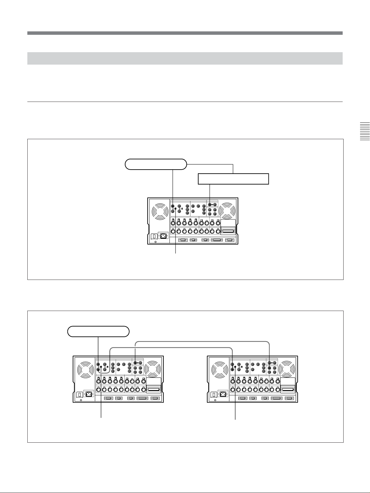
3-1 Connecting External Equipment
3-1-1 Making Digital Connections
Chapter 3 Setting Up the VTR
The diagram below shows how to connect this VTR to
another DVW-A500/1 series or 500/1 series VTR used
as a player and to a DVR-2100/2100P D-1 Component
DVW-A500/1 or DVW-500/1 series, or BVW-D75 series (player)
Input
COMPONENT or
COMPOSITE
VIDEO OUTPUT
DVW-A500/1 or DVW-500/1
series VTR
Digital VTR used as a recorder.
Chapter 3 Setting Up the VTR
SERIAL V/A OUTPUT
BNC cable
REMOTE1-IN
SERIAL V/A INPUT
SERIAL V/A OUTPUT
9-pin remote cable
BNC cable
BNC cable
Video monitor
BNC cable
REMOTE1-IN
9-pin remote cable
Output
Making digital connections
REMOTE1-OUT
REMOTE1
DVR-2100/2100P (recorder)
BNC cable
SERIAL V/A
INPUT
Chapter 3 Setting Up the VTR 3-1
Page 30

3-1 Connecting External Equipment
3-1-2 Making Analog Connections
The diagram below shows how to make connections
for analog video and audio signals from a Betacam/
Betacam SP VTR, 1-inch VTR, or D-2 VTR.
Chapter 3 Setting Up the VTR
REMOTE (9P)
ANALOG AUDIO
OUTPUT CH-1 to 4
Set the 75Ω
termination
9-pin remote cable
switch to OFF
when making a
bridge
connection for
an analog
composite video
signal.
Otherwise, set it
to ON.
DVR-28/20 D-2 VTR or
BVH-3000 1-inch VTR etc.
(player)
ANALOG VIDEO
OUTPUT
COMPOSITE VIDEO INPUT
(with BKDW-505/506)
REMOTE (9P)
COMPONENT
VIDEO
OUTPUT
COMPONENT VIDEO INPUT
ANALOG AUDIO INPUT CH-1 to 4
BVW-75/70/65/60 series
Betacam SP VTR (player)
COMPONENT or
COMPOSITE VIDEO OUTPUT
AUDIO
OUTPUT CH-1
to 4
Set the analog audio input level and impedance
using the AUDIO INPUT LEVEL/600Ω termination
switches as follows:
For line input with a 600Ω termination: HIGH with
ON
For high-impedance line input: HIGH with OFF
For high-impedance microphone input: LOW with
OFF
3-2 Chapter 3 Setting Up the VTR
Making analog connections
BNC cable
BNC cable
BNC cable
Video monitor
Page 31

3-2 Reference Signals for Video Output and Servo System
This section describes how reference signals for the
video output and servo system are selected.
generator is supplied as a reference signal for the video
output signals and servo circuits.
The output from the internal reference video signal
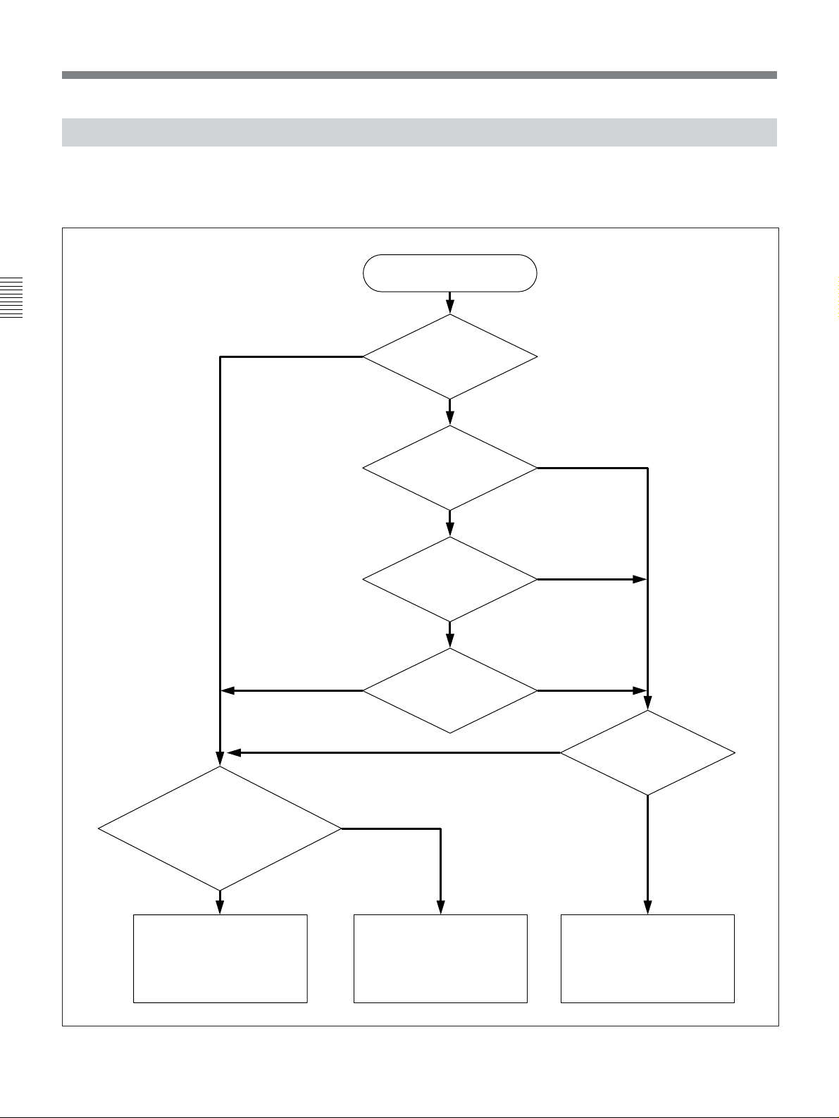
3-2-1 External Sync Signal for the Internal Reference Video Signal Generator
The internal reference video signal generator
synchronizes with either the input reference video
signal or a video input signal. Which of the two
signals is used for synchronization depends on the
signal input conditions and the setting of the [F2]
(OUT REF) button in the PF1 menu, as shown in the
following flow chart.
Start
Setting of the
[F6] (TCG SOURCE)
button in the TC
menu?
int
ext
Chapter 3 Setting Up the VTR
Is a signal being
input to the connector
selected by either the
VIDEO INPUT SELECT button or
the [F1] (VIDEO IN) button
in the PF1 menu?
Yes
The video signal input through the
connector, and selected by either the
VIDEO INPUT SELECT button or the
[F1] (VIDEO IN) button in the PF1
menu, is used for synchronization.
Automatic selection of external sync signal for the internal reference video signal generator
input
No
The reference video signal input
through one of the REF.VIDEO
INPUT connectors is used for
synchronization.
Setting of the
[F2] (OUT REF)
button in the
PF1 menu?
Is a signal
being input to one of the
REF.VIDEO INPUT
connectors?
Yes
ref
No
The internal reference video
signal generator is not
synchronized with any signal
(internal free-run).
Chapter 3 Setting Up the VTR 3-3
Page 32
3-2 Reference Signals for Video Output and Servo System
3-2-2 Reference Signal for the Servo System
The VTR automatically selects either the video input
signal or the output from the internal reference video
signal generator as the reference signal for the servo
Chapter 3 Setting Up the VTR
ext
system. Which of the two signals is selected depends
on the operational status of the VTR, as shown in the
following flow chart.
Start
Setting of the [F6]
(TCG SOURCE) button
in the TC menu?
int
Setting of the [F2]
(OUT REF) button in
the PF1 menu?
ref
Is the VTR
in edit mode?
input
Yes
Is a signal being input
to the connector selected by
either the VIDEO INPUT
SELECT button or the [F1]
(VIDEO IN) button in
the PF1 menu?
Yes
The servo locks with the
reference video signal being
input to either of the
REF.VIDEO INPUT connectors.
Automatic selection of reference signal for the servo system
No
No
No
The servo locks with the internal
reference video signal
generator.
Is the VTR in
recording mode?
Yes
No
Is a signal being
input to the video input
connector selected?
The servo locks with the video
input signal selected by either
the VIDEO INPUT SELECT
button or the [F1] (VIDEO IN)
button in the PF1 menu.
Yes
3-4 Chapter 3 Setting Up the VTR
Page 33
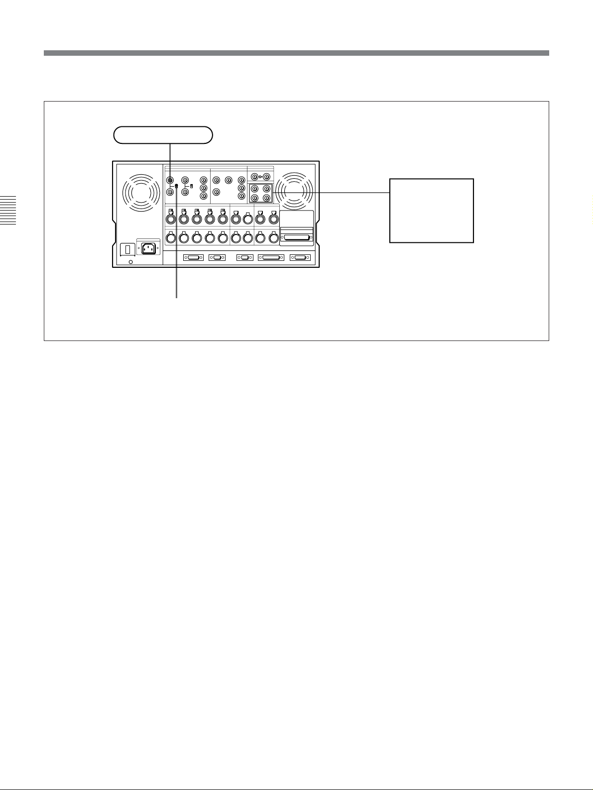
3-2-3 Reference Signals Connections
Make the reference signal connections as follows,
according to your recording or playback requirements.
Reference signal connections
For recording signals from a switcher or
signal generator
Reference signal
Chapter 3 Setting Up the VTR
Switcher or signal generator
REF.VIDEO INPUT
For recording signals from a switcher or signal generator
For recording signals from a VTR
Reference signal
REF.VIDEO INPUT
75Ω termination switch: ON
SERIAL V/A INPUT
SERIAL V/A INPUT
SERIAL V/A
OUTPUT
DVW-A500/1 series or DVW-500/1 series
(recorder)
75Ω termination switch: OFF
DVW-A510/510 series
(player)
75Ω termination switch: ON
For recording signals from a VTR
Chapter 3 Setting Up the VTR 3-5
Page 34
3-2 Reference Signals for Video Output and Servo System
For playback
Reference signal
REF.VIDEO INPUT
Chapter 3 Setting Up the VTR
75Ω termination switch: ON
For playback
SERIAL V/A
OUTPUT 1/2/3/
4(SUPER)
Serial monitor
3-6 Chapter 3 Setting Up the VTR
Page 35
3-3 Handling Cassettes
3-3-1 Recommended Cassettes
For the DVW-A500/1 series
You can use 1/2-inch Digital Betacam video cassettes
for both recording and playback, and 1/2-inch
Betacam/Betacam SP video cassettes for playback
only.
For the DVW-500/1 series
You can use 1/2-inch Digital Betacam video cassettes
only.
Digital Betacam cassettes
S-size cassettes
L-size cassettes
Betacam/Betacam SP cassettes
S-size
cassettes
L-size
cassettes
BCT-5MA/10MA/
20M
BCT-5MLA/
10MLA/20MLA/
30ML
90ML
BCT-D6/D12/D22/D32/D40
BCT-D34L/D64L/D94L/D124L
Oxide tapeMetal tape
BCT-5G/10G/20G/30G
A/30MA
BCT-5GL/10GL/20GL/
30GL/60GL/90GL
A/60MLA/
A
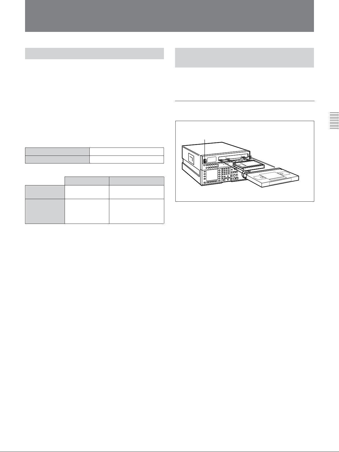
3-3-2 Inserting and Ejecting Cassettes
Always turn on the VTR before attempting to insert or
eject cassettes.
Inserting a cassette
Chapter 3 Setting Up the VTR
1
2
S-size cassette
L-size cassette
Inserting a cassette
1 Set the POWER switch to ON.
Storage of cassettes
Store your cassettes at room temperature and normal
humidity.
2 Before inserting a cassette, check the following
points:
•There is no slack in the tape.
•An error message does not appear in the menu
display.
•The window of the cassette is facing up.
If there is any slack in the tape, refer to “Removing
slack in the tape” on next page.
When inserting an S-size cassette, make sure it is
aligned with the marks on the cassette insertion
slot.
The cassette is loaded automatically, and the tape is
wound around the drum. The head-drum starts to
rotate, the tape stops, and the STANDBY and
STOP buttons light up.
When a Betacam/Betacam SP video cassette is
loaded into a DVW-A500/1 series VTR, the
DIGITAL indicator goes off.
When a Betacam/Betacam SP video cassette is
loaded into a DVW-500/1 series VTR, the cassette
is automatically ejected.
Chapter 3 Setting Up the VTR 3-7
Page 36

3-3 Handling Cassettes
Removing slack in the tape
Press one of the reels in slightly, then carefully rotate it
in the direction of the arrow until it stops.
Chapter 3 Setting Up the VTR
Preventing double cassette inserting
When a cassette is loaded, an orange lock-out bar
appears in the cassette insertion slot to prevent users
from attempting to load another cassette.
3-3-3 Preventing Accidental Erasure
To prevent accidental erasure of material recorded on a
tape, push in the record-protect plug.
L-size cassette
S-size cassette
Removing slack in the tape
Push in the record-protect plug. To restore the tape for
recording, return the plug to its original position.
Preventing accidental erasure
Ejecting the cassette
Press the EJECT button.
The tape is unthreaded and the cassette is
automatically ejected. This operation takes a few
seconds.
When a cassette with this plug pushed in is inserted
into the VTR, the REC INHIBIT indicator on the
lower control panel lights up and recording will not
start, even if you press the REC button.
To restore the tape for recording, return the plug to its
original position.
3-8 Chapter 3 Setting Up the VTR
Page 37

4-1 Registering and Storing Menu Settings
Chapter 4 Menu Settings
The operating conditions of the VTR are set by the
menu operation section on the lower control panel.
Menu items are divided among six different menus
(HOME, TC, CUE, PF1, PF2, SET UP).
Of these menus, the PF1/PF2 (Personal Function)
menus can be used to register frequently used menu
items from the other menus, allowing faster setting of
VTR operating conditions. Eight VTR memory banks
are provided for storing up to eight sets of menu
settings. The contents of the eight VTR memory
banks can, in turn, be stored on an IC memory card for
later recall.
4-1-1 Menu Configuration
In addition to the six main menus, the VTR has two
supplementary menus containing items not contained
in the main menus.
PF1&2 ASSIGN menu
This menu contains items that can be registered to the
PF1/2 menus.
Press the [F4] (PF1&2 ASSIGN) button in the SET UP
menu to display this menu.
For details on registering items in the PF1&2 ASSIGN
menu to the PF1/2 menus, refer to “4-1-3 Registering Items
to the PF1/2 Menus” on page 4-3.
Chapter 4 Menu Settings
VTR SETUP menu
This menu contains items that specify the initial
operating conditions of the VTR. You can change
these settings directly without registering the items to
the PF1/2 menus.
Press the [F6] (VTR SETUP) button in the SET UP
menu to display this menu.
For details on setting operating conditions of the VTR, refer
to “4-7-1 VTR SETUP Menu” on page 4-40.
The menu configuration of the VTR is shown in the
figure below,
HOME menu
TC menu
PF1 menu
PF2 menu
CUE menu
SET UP menu
[F4] (PF1&2 ASSIGN) button
[F6] (VTR SETUP) button
Registration
Menu configuration
PF1&2
ASSIGN menu
VTR SETUP
menu
¿
•All items in the HOME, TC, and CUE menus can be
duplicated and registered to the PF1/2 menus.
•Most items in the VTR SETUP menu can be
registered to the PF1/2 menus.
Chapter 4 Menu Settings 4-1
Page 38

4-1 Registering and Storing Menu Settings
To activate the HOME, TC, CUE, PF1, PF2, or SET
UP menu, press the respective menu button.
Menu items are assigned to function buttons ([F1] to
[F10]) in each menu. When two items are registered to
the same function button, you can display the second
item by pressing the ALT button.
The example below describes the procedure for
changing the setting of capstan servo lock mode
specified by the ALT button and [F5] (CAP LOCK)
button in the HOME menu.
Chapter 4 Menu Settings
4-1-2 Changing Menu Settings
1
23
Changing menu settings
2 Press the ALT button.
The second page of the HOME menu appears in
the display.
NR
DOLBY
RECINH
off
LOCK
TCR PLÅY NDF 4FD F1
PB/EE
PB/EE
ÅIN 00:00:00:00 ÅOUT 00:00:00:00
IN 00:00:00:00 OUT 00:00:00:00
FREEZE
P-ROLL
CÅP
LOCK
2FD
CH.COND
DIGITÅL
GREEN
01Ó04µ58ß00
ÅLT+HOME
BÅSEBÅLL EDIT SET
ƒ
DMC P-PLÅY
TIME
5S
LÅST
EDIT
To return to the first page
Press the ALT button again.
3 Press the [F5] (CAP LOCK) button to change the
capstan servo lock mode setting.
Each press of the button changes the setting.
Changing menu settings using the cursor
control buttons
1 Press the HOME button.
The first page of the HOME menu appears in the
display.
NR
CH.COND
DIGITÅL
DOLBY
PRE
REÅD
off
LOCK
TCR PLÅY 4FD F1
CONFI
off
ÅIN 00:00:00:00 ÅOUT 00:00:00:00
ÅSSEM-
IN 00:00:00:00 OUT 00:00:00:00
BLE
off
INS
TC
off
INS
VIDEO
Å-CH1
off
GREEN
01Ó04µ58ß00
INS
INS
Å-CH2
off
Å-CH3
off
HOME
BÅSEBÅLL EDIT SET
ƒ
INS
INS
INS
Å-CH4
off
CUE
off
off
You may also use the cursor control buttons to select
menu items and change menu settings by moving the
on-screen cursor.
For settings which cannot be made by the function
buttons alone, the following icons appear in the
bottom-right of the menu to indicate the use of the
cursor control buttons:
: All cursor control buttons
: Cursor control buttons for horizontal
direction
: Cursor control buttons for vertical direction
In addition to operations using the cursor control
buttons, some menus allow you to change a value by
using the +/– buttons.
4-2 Chapter 4 Menu Settings
Page 39

4-1-3 Registering Items to the PF1/2 Menus
You can register up to 40 items to the PF (Personal
Function) 1/2 menus, including items that are
displayed when the ALT button is pressed. The
registration of items from different menus to the PF1/2
menus eliminates the need for changing menus in
order to change a given VTR operating condition.
For details on the factory-set PF1/2 menus, refer to “4-5
PF1 Menu (Factory Settings)” on page 4-33 and “4-6 PF2
Menu (Factory Settings)”on page 4-36.
PF1
ÅLT+PF1 SETUP MENU
ÅLT+
F6KEY SETUP ITEM-610
PF1
1:710 605:TCG REGEN
REGEN
2:110 606:TC OUT SIG.
Selected function
button
Item currently
registered to the
button
MODE
3:201 607:BINÅRY GP
as&in
PF2
4:203 608:PHÅSE CORR.
5: 609:TCG CF FLÅG
6:610 610:REGEN MODE
7: 611:TC RGN SRC
ÅLT+
8:703 701:EE DELÅY
PF2
9:704 703:BLÅNK LINE
10: 704:DEC MODE
SET
BLÅNK
PÅSTE CANCEL
To cancel a currently registered item
Press the [F6] (SET BLANK) button.
SÅVE/
EXIT
Registering items to the PF1/2 menus
23 4,5
6 8
Registering items to the PF1/2 menus
1
1 Press the SET UP button.
The SET UP menu appears in the display.
2 Press the [F4] (PF1&2 ASSIGN) button.
The PF1&2 ASSIGN menu appears in the display.
3 Press the [F1] (PF1), [F2] (ALT+PF1), [F3] (PF2)
or [F4] (ALT+PF2) button to select the PF menu
where you wish to register an item.
The selected PF menu appears and the items
currently registered to the menu appear at the left
of the display.
5 Press the F button to move the cursor (z) to the
PF1&2 ASSIGN menu, then press the G or g
button to move the cursor to the menu item to be
registered to the function button.
To scroll the menu faster
Press the G or g button while holding down the
SFT button.
PF1
ÅLT+PF1 SETUP MENU
ÅLT+
F6KEY SETUP ITEM-610
PF1
1:710 605:TCG REGEN
REGEN
2:110 606:TC OUT SIG.
MODE
3:201 607:BINÅRY GP
as&in
PF2
4:203 608:PHÅSE CORR.
5: 609:TCG CF FLÅG
6:610 610:REGEN MODE
7: 611:TC RGN SRC
ÅLT+
8:703 701:EE DELÅY
PF2
9:704 703:BLÅNK LINE
10: 704:DEC MODE
SET
PÅSTE CANCEL
BLÅNK
SÅVE/
EXIT
Item to be
registered to the
function button
6 Press the [F7] (PASTE) button to register the item.
The new item is registered to the function button.
7 Repeat Steps 3 to 6 to register more items.
To cancel the registration of all new items
Press the [F9] (CANCEL) button.
Chapter 4 Menu Settings
4 Press the G or g button to move the cursor (z) to
the function button where the item is to be
registered.
The selected function button is highlighted and the
currently registered item appears.
8 Press the [F10] (SAVE/EXIT) button to save the
newly registered items.
The registration is completed and the SET UP
menu appears in the display again.
Chapter 4 Menu Settings 4-3
Page 40

4-1 Registering and Storing Menu Settings
Eight VTR memory banks are provided for storing up
to eight sets of menu settings including items
registered to the PF1/2 menus with titles.
The contents of all eight VTR memory banks can be
stored on an IC memory card.
Chapter 4 Menu Settings
For details on IC memory card use, refer to “4-1-5 IC
Memory Card Function” on page 4-6.
For details on adding titles to the contents of the VTR
memory bank, refer to “4-1-6 Adding Titles to the Data” on
page 4-11.
4-1-4 VTR Memory Bank Function
Current menu settings in the
VTR (CURRENT SETUP).
These settings are stored in
addition to the VTR memory
banks when the power is
turned off.
Storing/recalling
IC memory card (SETUP
BANK 0 to 8). The card
stores setting data in same
way as the VTR memory
banks. These contents can
be later called up in the
VTR.
VTR memory bank function
VTR memory banks (SETUP
BANK1 to 8 and [F]). SETUP
BANK[F] contains the factoryset menu settings. By calling
up SETUP BANK [F], you can
restore all menu items to their
factory settings.
Storing/recalling
Storing/recalling
Storing the current VTR menu settings to
a VTR memory bank
4
6,7
CLR button
153
2
Storing the current VTR menu settings to a VTR memory bank
1 Press the SET UP button.
The SET UP menu appears in the display.
2 Press the [F1] (VTR BANK) button.
The VTR BANK menu appears in the display.
VTR BÅNK VTR BÅNK
CURRENT SETUP SETUP BÅNK1
2
3
4 FOOTBÅLL12
5 (PRESET)
6
7 (PRESET)
8
ƒ (PRESET)
EDIT
TITLE
ç
DIREC-
VTR BÅNK
TCR 00:00:00:00
1
COPY EXIT
TION
<<
3 Press the [F8] (DIRECTION) button to select >>.
Note
The contents of SETUP BANK[F] cannot be changed.
4-4 Chapter 4 Menu Settings
4 Press the f button to move the cursor (z) to
CURRENT SETUP[C], then press the [F6] (EDIT
TITLE) button to add a title to the current menu
settings of the VTR.
For details, refer to “4-1-6 Adding Titles to the Data”
on page 4-11.
5 Press the F button to move the cursor (z) to
SETUP BANK, then press the G or g button to
move the cursor to the number of the VTR
memory bank to be used for saving the current
menu settings.
Page 41

6 Press the [F9] (COPY) button.
A message asking you to confirm the operation
appears in the display.
To cancel the storage operation
Press the CLR button.
1 Press the SET UP button.
The SET UP menu appears in the display.
2 Press the [F1] (VTR BANK) button.
The VTR BANK menu appears in the display.
7 Press the [F9] (COPY) button while holding down
the SFT button.
The current menu settings are stored to the VTR
memory bank.
To add or change a title for VTR settings
after storing them to the VTR memory bank
Move the cursor (z) to the number of the VTR
where the settings are stored, then press the [F6]
(EDIT TITLE) button.
BÅCK
SPÅCE
EDIT TITLE
B
6789:;<=>?@Å BCDEFGHIJKLM
SET
LETTER
SÅVE/
CÅNCELSPÅCE
EXIT
8 Press the [F10] (EXIT) button.
The SET UP menu appears again.
Recalling menu settings from a VTR
memory bank
VTR BÅNK VTR BÅNK
CURRENT SETUP SETUP BÅNK1
1
2
3
4 FOOTBÅLL12
5 (PRESET)
6
7 (PRESET)
8
ƒ (PRESET)
EDIT
TITLE
DIREC-
VTR BÅNK
TCR 00:00:00:00
COPY EXIT
TION
<<
3 Press the [F8] (DIRECTION) button and select <<.
4 Press the G or g button to move the cursor (z) to
the number of the VTR memory bank to be
recalled.
5 Press the [F9] (COPY) button.
A message asking you to confirm the operation
appears in the display.
To cancel the recalling operation
Press the CLR button.
6 Press the [F9] (COPY) button while holding down
the SFT button.
The menu settings are recalled from the selected
VTR memory bank.
When the recalling process has been completed,
the title of the VTR bank appears under
CURRENT SETUP in the display.
Chapter 4 Menu Settings
2
5,6
7
143
Recalling menu settings from a VTR memory bank
VTR BÅNK VTR BÅNK
CURRENT SETUP SETUP BÅNK1
FOOTBÅLL12 1
2
3
4 FOOTBÅLL12
5 (PRESET)
6
7 (PRESET)
8
ƒ (PRESET)
EDIT
TITLE
DIREC-
VTR BÅNK
TCR 00:00:00:00
COPY EXIT
TION
<<
Chapter 4 Menu Settings 4-5
(Continued)
Page 42
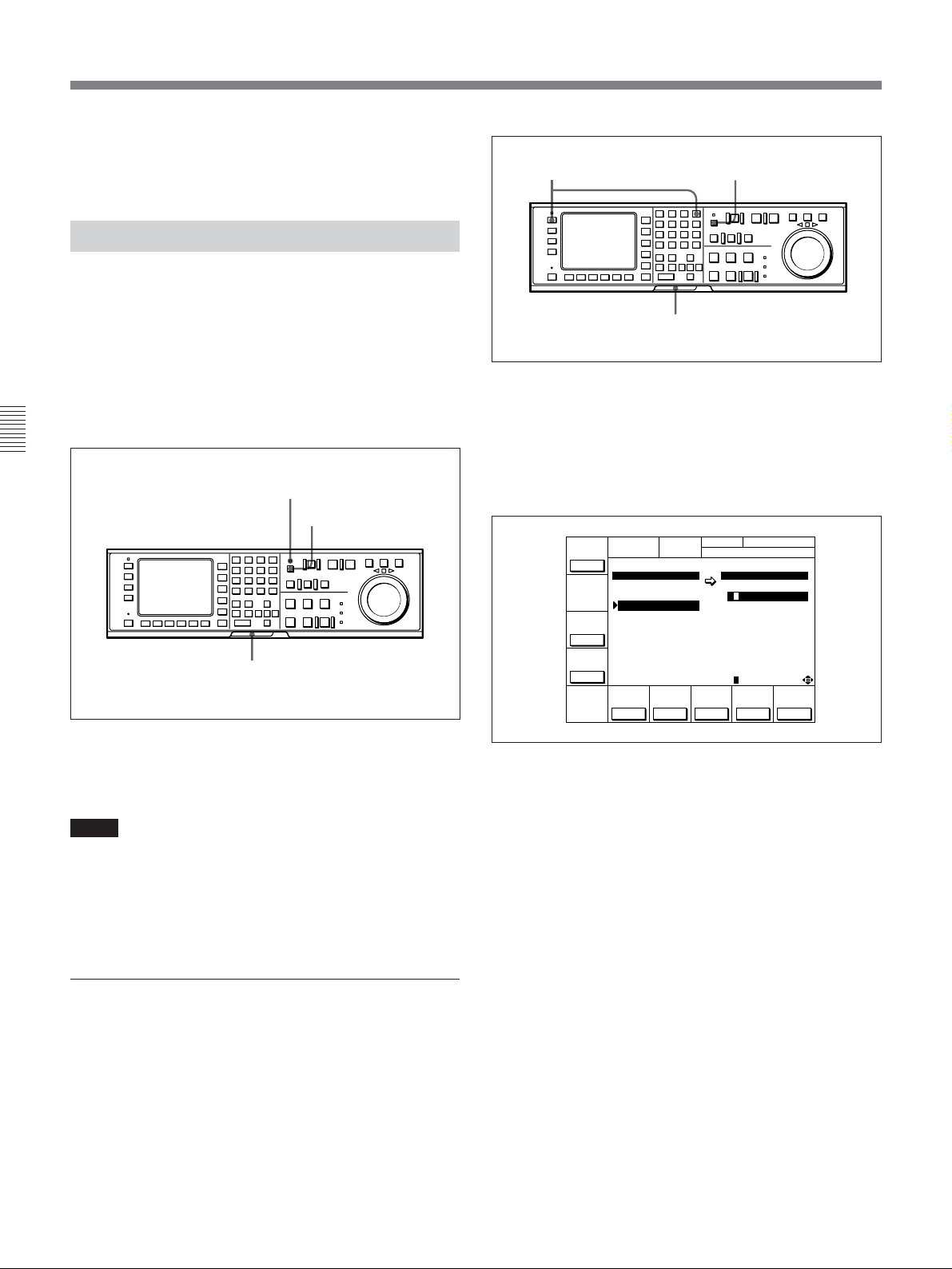
4-1 Registering and Storing Menu Settings
7 Press the [F10] (EXIT) button.
The SET UP menu appears again.
4-1-5 IC Memory Card Function
You can store menu settings in the VTR memory
banks and cue point data to an IC memory card for
later recalling.
The MEMORY CARD indicator lights up when you
insert an IC memory card.
You can then access the MEMORY CARD menu
directly from other menus (HOME/TC/CUE/PF1/PF2)
by pressing the ACCESS button.
1 Insert the IC memory card.
3,4,5 2
1
Formatting an IC memory card
The MEMORY CARD indicator lights up.
Chapter 4 Menu Settings
To eject the IC memory card
Press the button to the right of the insertion slot.
Notes
•Insert the IC memory card fully until it clicks.
•The ACCESS button flashes while the VTR is
writing to or reading from an IC memory card. Do
not eject the IC memory card while the indicator is
flashing.
Formatting an IC memory card
MEMORY CARD indicator
ACCESS button
IC Memory card insertion slot
IC memory card function
2 Press the ACCESS button.
MEMORY CARD menu appears in the display.
FORMÅT
CÅRD
MEMORY CÅRD VTR BÅNK
SETUP BÅNK1 CURRENT SETUP
0 ç BÅSEBÅLL
BÅSEBÅLL 1 1
(PRESET) 2 2
SHOW
(PRESET) 3 3 FOOTBÅLL12
SETUP
4 4 (PRESET)
5 5
6 6 (PRESET)
SHOW
(PRESET) 7 7
CUESET
8 8
EDIT
TITLE
...
SELECT
DIREC-
ÅLL
MEMORY CÅRD
BÅSEBÅLL EDIT
TCR 00:00:00:00
ƒ (PRESET)
COPY EXIT
TION
>>
...
3 Press the [F1] (FORMAT CARD) button.
A message asking you to confirm the operation
appears in the display.
4 Press the [F1] (FORMAT CARD) button while
holding down the SFT button.
A message asking you to confirm the operation
appears in the display again.
5 Press the [F1] (FORMAT CARD) button while
holding down the SFT button.
The VTR starts formatting the card.
The supplied IC memory card or other IC memory
cards must be formatted before you can use them.
4-6 Chapter 4 Menu Settings
To cancel formatting
Press the CLR button while the confirmation
message appears in the display.
Page 43

Storing the contents of the VTR memory
banks to an IC memory card
7,8
2
6
Storing the contents of the VTR memory banks to an IC memory card
91 4,53
5 Press the F button to move the cursor (z) to the
VTR side, then press the G or g button to move
the cursor to the number of the VTR memory bank
to be stored.
FORMÅT
CÅRD
MEMORY CÅRD VTR BÅNK
SETUP BÅNK4 SETUP BANK3
0 ç BÅSEBÅLL
BÅSEBÅLL 1 1
(PRESET) 2 2
SHOW
(PRESET) 3
SETUP
4 4 (PRESET)
5 5
6 6 (PRESET)
SHOW
(PRESET) 7 7
CUESET
8 8
EDIT
TITLE
...
SELECT
DIREC-
ÅLL
MEMORY CÅRD
BÅSEBÅLL EDIT
TCR 00:00:00:00
3 FOOTBÅLL12
ƒ (PRESET)
COPY EXIT
TION
<<
...
VTR memory
bank number
1 Press the SET UP button.
The SET UP menu appears in the display.
2 Press the [F2] (MEMORY CARD) button.
The MEMORY CARD menu appears in the
display.
You can access the MEMORY CARD menu
directly by pressing the ACCESS button.
FORMÅT
CÅRD
MEMORY CÅRD VTR BÅNK
SETUP BÅNK1 CURRENT SETUP
0 ç BÅSEBÅLL
BÅSEBÅLL 1 1
(PRESET) 2 2
SHOW
(PRESET) 3 3 FOOTBÅLL12
SETUP
4 4 (PRESET)
5 5
6 6 (PRESET)
SHOW
(PRESET) 7 7
CUESET
8 8
EDIT
TITLE
...
SELECT
DIREC-
ÅLL
MEMORY CÅRD
BÅSEBÅLL EDIT
TCR 00:00:00:00
ƒ (PRESET)
COPY EXIT
TION
>>
...
3 Press the [F8] (DIRECTION) button and select <<.
4 Press the G or g button to move the cursor (z) to
the number of the VTR memory bank in the IC
memory card where the data are to be stored.
Bank number in
the IC memory card
FORMÅT
CÅRD
MEMORY CÅRD VTR BÅNK
SETUP BÅNK4 CURRENT SETUP
0 ç BÅSEBÅLL
BÅSEBÅLL 1 1
(PRESET) 2 2
SHOW
(PRESET) 3 3 FOOTBÅLL12
SETUP
4 4 (PRESET)
5 5
6 6 (PRESET)
SHOW
(PRESET) 7 7
CUESET
8 8
EDIT
TITLE
...
SELECT
ÅLL
DIREC-
MEMORY CÅRD
BÅSEBÅLL EDIT
TCR 00:00:00:00
ƒ (PRESET)
COPY EXIT
TION
<<
...
To store the current VTR menu settings
only
Move the cursor (z) to the [C] (CURRENT
SETUP) position.
To store all VTR memory banks
Press the [F7] (SELECT ALL) button.
6 To change the title of the bank, press the [F6]
(EDIT TITLE) button.
For details, refer to “4-1-6 Adding Titles to the
Data”on page 4-11.
7 Press the [F9] (COPY) button.
A message asking you to confirm the operation
appears in the display.
8 Press the [F9] (COPY) button while holding down
the SFT button.
The control panel stores the specified VTR
memory bank to the IC memory card.
After the storage is complete, the title of the VTR
memory bank appears under the MEMORY CARD
indication.
FORMÅT
CÅRD
MEMORY CÅRD VTR BÅNK
SETUP BÅNK4 SETUP BANK3
0 ç BÅSEBÅLL
BÅSEBÅLL 1 1
(PRESET) 2 2
SHOW
(PRESET) 3
SETUP
FOOTBÅLL12 4 4 (PRESET)
5 5
6 6 (PRESET)
SHOW
(PRESET) 7 7
CUESET
8 8
EDIT
TITLE
...
SELECT
DIREC-
ÅLL
MEMORY CÅRD
BÅSEBÅLL EDIT
TCR 00:00:00:00
3 FOOTBÅLL12
ƒ (PRESET)
COPY EXIT
TION
<<
...
Chapter 4 Menu Settings
(Continued)
Chapter 4 Menu Settings 4-7
Page 44

4-1 Registering and Storing Menu Settings
9 Press the [F10] (EXIT) button.
Storing cue point lists to an IC memory
card
You can store up to 8 pages of cue point lists to an IC
memory card along with titles.
Chapter 4 Menu Settings
1 Press the SET UP button.
2 Press the [F2] (MEMORY CARD) button.
The SET UP menu or the menu displayed before
you pressed the ACCESS button appears again.
6,7
23
91 54
8
Storing cue point lists to an IC memory card
The SET UP menu appears in the display.
The MEMORY CARD menu appears in the
display.
You can access MEMORY CARD menu directly
by pressing the ACCESS button.
FORMÅT
CÅRD
MEMORY CÅRD VTR BÅNK
SETUP BÅNK1 CURRENT SETUP
0 ç BÅSEBÅLL
BÅSEBÅLL 1 1
(PRESET) 2 2
SHOW
(PRESET) 3 3 FOOTBÅLL12
SETUP
4 4 (PRESET)
5 5
6 6 (PRESET)
SHOW
(PRESET) 7 7
CUESET
8 8
EDIT
TITLE
...
SELECT
ÅLL
DIREC-
MEMORY CÅRD
BÅSEBÅLL EDIT
TCR 00:00:00:00
ƒ (PRESET)
COPY EXIT
TION
>>
...
3 Press the [F4] (SHOW CUESET) button.
The display for storing cue point lists appears.
FORMÅT
CÅRD
MEMORY CÅRD VTR BÅNK
CUE POINT SET1 CURRENT CUESET
0 ç BÅSEBÅLL
(Blank) 1
(Blank) 2
SHOW
(Blank) 3
SETUP
4
5
6
SHOW
7
CUESET
(Blank) 8
EDIT
TITLE
SELECT
ÅLL
DIREC-
MEMORY CÅRD
BÅSEBÅLL EDIT
TCR 00:00:00:00
(Blank)
ƒ
COPY EXIT
TION
>>
...
To return to the SET UP menu
Press the [F3] (SHOW SETUP) button.
4 Press the [F8] (DIRECTION) button to select <<.
5 Press the G or g button to move the cursor (z) to
the number of the memory bank in the IC memory
card where you want to store the cue point list.
Bank number in
the IC memory card
FORMÅT
CÅRD
MEMORY CÅRD VTR BÅNK
CUE POINT SET1 CURRENT CUESET
0 ç BÅSEBÅLL
(Blank) 1
(Blank) 2
SHOW
(Blank) 3
SETUP
4
5
6
SHOW
7
CUESET
(Blank) 8
EDIT
TITLE
SELECT
ÅLL
DIREC-
MEMORY CÅRD
BÅSEBÅLL EDIT
TCR 00:00:00:00
(Blank)
ƒ
COPY EXIT
TION
>>
...
6 Press the [F9] (COPY) button.
A message asking you to confirm the operation
appears in the display.
7 Press the [F9] (COPY) button while holding down
the SFT button.
The VTR stores the cue point list to the IC memory
card.
4-8 Chapter 4 Menu Settings
Page 45

8 Press the [F6] (EDIT TITLE) button to add a title
to the cue point list.
For details, refer to “4-1-6 Adding Titles to the
Data”on page 4-11.
9 Press the [F10] (EXIT) button.
The SET UP menu or the menu displayed before
you pressed the ACCESS button appears again.
Recalling the contents of an IC memory
card
The contents stored in an IC memory card can be
recalled to the current VTR bank or VTR memory
bank.
7,8
2
4 Press the G or g button to move the cursor (z) to
the number of the memory bank in the IC memory
card whose contents are to be recalled.
Bank number in
the IC memory card
FORMÅT
CÅRD
MEMORY CÅRD VTR BÅNK
SETUP BÅNK1 CURRENT SETUP
0 ç BÅSEBÅLL
BÅSEBÅLL 1 1
(PRESET) 2 2
SHOW
(PRESET) 3 3 FOOTBÅLL12
SETUP
4 4 (PRESET)
5 5
6 6 (PRESET)
SHOW
(PRESET) 7 7
CUESET
8 8
EDIT
TITLE
...
SELECT
DIREC-
ÅLL
MEMORY CÅRD
BÅSEBÅLL EDIT
TCR 00:00:00:00
ƒ (PRESET)
COPY EXIT
TION
>>
...
5 To change the title of the memory bank, press the
[F6] (EDIT TITLE) button.
You can also change a title after recalling its
respective contents from the memory bank.
For details, refer to“4-1-6 Adding Titles to the Data”on
page 4-11.
Chapter 4 Menu Settings
91 4,63
5
Recalling the contents of an IC memory card
1 Press the SET UP button.
The SET UP menu appears in the display.
2 Press the [F2] (MEMORY CARD) button.
The MEMORY CARD menu appears in the
display.
You can access MEMORY CARD menu directly
by pressing the ACCESS button.
FORMÅT
CÅRD
MEMORY CÅRD VTR BÅNK
SETUP BÅNK1 CURRENT SETUP
0 ç BÅSEBÅLL
BÅSEBÅLL 1 1
(PRESET) 2 2
SHOW
(PRESET) 3 3 FOOTBÅLL12
SETUP
4 4 (PRESET)
5 5
6 6 (PRESET)
SHOW
(PRESET) 7 7
CUESET
8 8
EDIT
TITLE
...
SELECT
DIREC-
ÅLL
MEMORY CÅRD
BÅSEBÅLL EDIT
TCR 00:00:00:00
ƒ (PRESET)
COPY EXIT
TION
>>
...
6 Press the F button to move the cursor (z) to the
VTR side, then press the G or g button to move
the cursor to the VTR memory bank number where
the recalled data are to be stored.
FORMÅT
CÅRD
MEMORY CÅRD VTR BÅNK
SETUP BÅNK1 SETUP BÅNK 7
0 ç BÅSEBÅLL
BÅSEBÅLL 1 1
(PRESET) 2 2
SHOW
(PRESET) 3 3 FOOTBÅLL12
SETUP
4 4 (PRESET)
5 5
6 6 (PRESET)
SHOW
(PRESET) 7 7
CUESET
8 8
EDIT
TITLE
...
SELECT
DIREC-
ÅLL
MEMORY CÅRD
BÅSEBÅLL EDIT
TCR 00:00:00:00
ƒ (PRESET)
COPY EXIT
TION
...
VTR memory
bank number
To change the current VTR menu settings
Move the cursor (z) to [C] (CURRENT SETUP).
To replace all VTR memory bank contents
with IC memory card data
Press the [F7] (SELECT ALL) button.
7 Press the [F9] (COPY) button.
A message asking you to confirm the operation
appears in the display.
3 Press the [F8] (DIRECTION) button to select >>.
(Continued)
Chapter 4 Menu Settings 4-9
Page 46
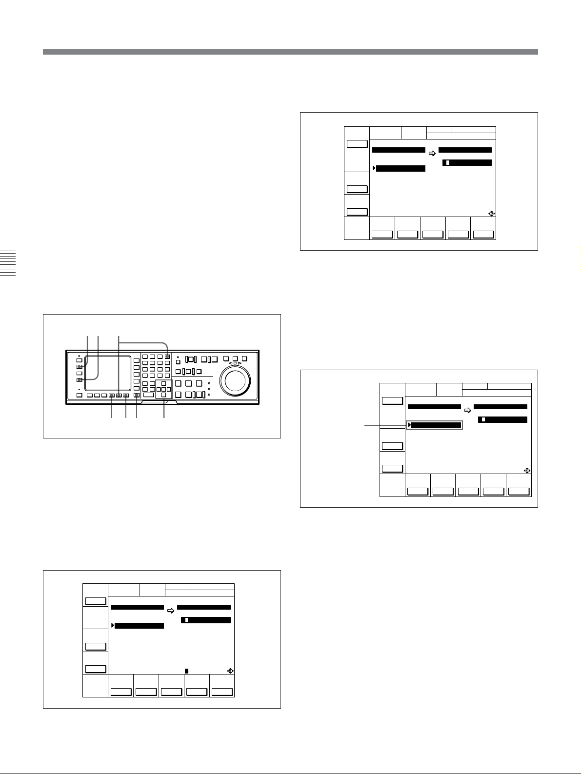
4-1 Registering and Storing Menu Settings
8 Press the [F9] (COPY) button while holding down
9 Press the [F10] (EXIT) button.
Recalling a cue point list in an IC memory
card
Chapter 4 Menu Settings
Recalling a cue point list in an IC memory card
replaces the current VTR cue point list with the
recalled data.
the SFT button.
The VTR recalls the contents of the memory card.
After the recalling process is complete, the title of
the memory bank of the memory card appears
under the VTR indication.
The SET UP menu or the menu displayed before
you pressed the ACCESS button appears again.
6,7
23
3 Press the [F4] (SHOW CUESET) button.
The menu for storing cue point lists appears.
FORMÅT
CÅRD
MEMORY CÅRD VTR BÅNK
SETUP BÅNK1 CURRENT CUESET
0 ç BÅSEBÅLL
SHOW
SETUP
SHOW
CUESET
EDIT
BÅSEBÅLL 1
(PRESET) 2
(PRESET) 3
4
5
6
(PRESET) 7
8
TITLE
...
SELECT
DIREC-
ÅLL
MEMORY CÅRD
BÅSEBÅLL EDIT
TCR 00:00:00:00
COPY EXIT
TION
>>
...
To return to the SET UP menu
Press the [F3] (SHOW SETUP) button again.
4 Press the [F8] (DIRECTION) button to select >>.
5 Press the G or g button to move the cursor (z) to
the number of the memory bank in the IC memory
card.
81 54
Recalling a cue point list in an IC memory card
1 Press the SET UP button.
The SET UP menu appears in the display.
2 Press the [F2] (MEMORY CARD) button.
The MEMORY CARD menu appears in the
display.
You can access MEMORY CARD menu directly
by pressing the ACCESS button.
FORMÅT
CÅRD
MEMORY CÅRD VTR BÅNK
SETUP BÅNK1 CURRENT SETUP
0 ç BÅSEBÅLL
BÅSEBÅLL 1 1
(PRESET) 2 2
SHOW
(PRESET) 3 3 FOOTBÅLL12
SETUP
4 4 (PRESET)
5 5
6 6 (PRESET)
SHOW
(PRESET) 7 7
CUESET
8 8
EDIT
TITLE
...
SELECT
ÅLL
DIREC-
MEMORY CÅRD
BÅSEBÅLL EDIT
TCR 00:00:00:00
ƒ (PRESET)
COPY EXIT
TION
>>
...
Bank number of
the IC memory card
FORMÅT
CÅRD
MEMORY CÅRD VTR BÅNK
SETUP BÅNK1 CURRENT CUESET
0 ç BÅSEBÅLL
SHOW
SETUP
SHOW
CUESET
EDIT
BÅSEBÅLL 1
(PRESET) 2
(PRESET) 3
4
5
6
(PRESET) 7
8
TITLE
...
SELECT
DIREC-
ÅLL
MEMORY CÅRD
BÅSEBÅLL EDIT
TCR 00:00:00:00
COPY EXIT
TION
>>
...
6 Press the [F9] (COPY) button.
A message asking you to confirm the operation
appears in the display.
7 Press the [F9] (COPY) button while holding down
the SFT button.
The VTR recalls the cue point list in the IC
memory card.
After the recalling process is completed, the name
of the cue point list appears under the CURRENT
CUESET indication.
4-10 Chapter 4 Menu Settings
Page 47

8 Press the [F10] (EXIT) button.
The SET UP menu or the menu displayed before
you pressed the ACCESS button appears again.
4-1-6 Adding Titles to the Data
When storing data to a memory bank in an IC memory
card or the VTR, you can add a title to the data to
make data management easier.
2
5 1,34
Adding titles to the data
1 Move the cursor (z) to CURRENT SETUP[C] or
the number of the memory bank in the IC memory
card.
3 Press the f or F button to select a letter.
BÅCK
SPÅCE
EDIT TITLE
B
6789:;<=>?@ÅB CDEFGHIJKLM
SET
LETTER
SÅVE/
CÅNCELSPÅCE
EXIT
4 Press the [F7] (SET LETTER) button .
The selected letter is entered.
BÅCK
SPÅCE
EDIT TITLE
6789:;<=>?@ÅB CDEFGHIJKLM
SET
LETTER
SÅVE/
CÅNCELSPÅCE
EXIT
Chapter 4 Menu Settings
2 Press the[F6](EDIT TITLE) button to display the
EDIT TITLE widnow.
BÅCK
SPÅCE
EDIT TITLE
B
6789:;<=>?@Å BCDEFGHIJKLM
SET
LETTER
SÅVE/
CÅNCELSPÅCE
EXIT
5 Repeat Steps 3 and 4 to enter more characters.
To enter a space
Press the [F5] (SPACE) button.
If you enter a wrong character
Press the [F6] (BACK SPACE) to go back, then
reenter a character.
To cancel the procedure to start again
Press [F9] (CANCEL) button, then reenter a
character.
6 Press the [F10] (SAVE/EXIT) button.
The entered title is set and the menu displayed
before you pressed the EDIT TITLE button
appears again.
Chapter 4 Menu Settings 4-11
Page 48

4-1 Registering and Storing Menu Settings
Most setting of most items can be stored to a VTR
memory bank or an IC memory card, with the
exception of the settings described below:
Data that can be stored to/recalled from a VTR
memory bank or IC memory card
•Settings of items in the VTR SETUP menu (with the
exceptions listed below)
•Contents of the PF1/2 menus
•VTR memory bank titles
Chapter 4 Menu Settings
Data that cannot be stored to a VTR memory
bank or an IC memory card
Settings of the following items in the VTR SETUP
menu are not stored to memory:
•603. ID CODE
•Items related to the hours meter (H01 to H14)
Current settings are always maintained for these items.
4-1-7 Details on VTR Memory Bank and IC Memory Card Functions
•Settings for items that exist only on VTR A and have
been assigned to the PF1/2 menus are not read, and
the respective function buttons do not appear in menu
display on the BKDW-515 attached to VTR B.
4-1-8 IC Memory Card Data
Compatibility Among the DVWA500/1 and DVW-500/1 Series
VTRs
IC memory card data recorded on one DVW-A500/1
series or 500/1 series VTR (VTR A) can be read into
the VTR memory banks of another DVW-A500/1
series or DVW-500/1 series VTR (VTR B) and
equipped with the BKDW-515. If both VTRs are
identical in model and optional accessories, the entire
IC memory card contents are read and applied as is. If
the VTRs differ either in model or optional
accessories, the following will occur:
•Settings for those items that are common to both
VTR A and VTR B are read (i.e, items that are
common to most VTRs and unaffected by series or
configuration differences).
•Settings that exist on VTR B but not on VTR A
remain unchanged.
For example, if VTR A is a DVW-500/1 and VTR B
is a DVW-A500/1, the analog Betacam playback
settings on VTR B are not changed by data input
from the IC memory card.
•Settings for items that exist only on VTR A are not
read.
4-12 Chapter 4 Menu Settings
Page 49

4-2 HOME Menu
The HOME menu sets the basic VTR operation
conditions for recording, playback, and editing.
The HOME, TC, PF1 and PF2 menus show
information that includes the VTR operation mode,
time code of the current position, and time code type,
etc.
Channel condition Signal format of the playback tape
NR
CH.COND
GREEN
01Ó04µ58ß00
INS
INS
INS
Å-CH2
off
Å-CH3
off
off
HOME menu display
Operation mode
DOLBY
PRE
KEY-INH
REÅD
off
LOCK
TCR PLÅY 4FD F1
CONFI
off
ÅIN 00:00:00:00 ÅOUT 00:00:00:00
ÅSSEM-
IN 00:00:00:00 OUT 00:00:00:00
BLE
off
INS
TC
off
INS
VIDEO
Å-CH1
off
To activate the HOME menu
Press the HOME button.
To change the HOME menu page
Press the ALT button.
DIGITÅL
HOME
BÅSEBÅLL EDIT SET
ƒ
INS
off
INS
CUE
off
Å-CH4
Name of the displayed menu
Title of the current VTR SETUP menu
Capstan lock mode
Chapter 4 Menu Settings
For details on time codes, refer to “4-3 TC Menu” on page
4-18.
HOME menu
Button
[F1]
[F2] CONFI
[F3]
[F4] INS TC
[F5] INS VIDEO
[F6] INS A-CH1
[F7]
[F8] INS A-CH3
[F9] INS A-CH4
[F10] INS CUE
ALT/[F1] REC INH Selects the REC INH (record inhibit) mode. off, [all, crash, video, audio]
ALT/[F2] PB/EE Selects the monitor mode. PB/EE, PB
ALT/[F3] FREEZE Selects the still-picture function setting. on, off
ALT/[F5] CAP LOCK
ALT/[F6]
ALT/[F7]
ALT/[F8]
ALT/[F10] LAST EDIT Restores the last edit point set.
Indication Function Settings
PRE READ
Selects the PRE READ function setting. off, [video, audio, a/v]
Selects the simultaneous playback setting. on, off
ASSEMBLE
Selects the edit mode and edit channel.
on, off
INS A-CH2
Selects CAP LOCK (capstan servo lock) mode.
2FD, 4FD, 8FD (DVW-A500P/1 and
500P/1 only)
P-ROLL TIME Sets the preroll time.
DMC
P-PLAY
Selects DMC playback.
Selects program playback.
0 to 30 s
Chapter 4 Menu Settings 4-13
Page 50

4-2 HOME Menu
4-2-1 Setting the Preread Function (PRE READ)
To perform prereading during insert edit mode, press
the [F1] (PRE READ) button while holding down the
SFT button.
Each press of the [F1] (PRE READ) button selects off,
video, audio or a/v. Select video, audio, a/v through
319. PREREAD SELECT in the VTR SETUP menu.
off: The preread function is disabled.
video: Video signals are preread.
audio: Audio signals are preread.
a/v: Both video and audio signals are preread.
Chapter 4 Menu Settings
[F1] button SFT button
You can use the preread function to perform prepread
editing.
For details, refer to “6-2-4 Performing Preread Editing” on
page 6-18.
Setting the preread function
4-2-3 Selecting the Edit Mode and Edit Channel (ASSEMBLE to INS CUE)
Selects assemble or insert edit mode.
Selecting assemble edit mode
After setting the [F4] (INS TC) to [F10] (INS CUE)
buttons to off, set the [F3] (ASSEMBLE) button to on.
Selecting the insert edit mode
Set the [F3] (ASSEMBLE) button to off and select the
required insert channel by pressing the [F4] (INS TC)
button to [F10] (INS CUE) button.
Selecting the insert channel
[F4] (INS TC) button: Time Code
[F5] (INS VIDEO) button: Video signal
[F6] (INS A-CH1) button: Digital audio signal
(channel 1)
[F7] (INS A-CH2) button: Digital audio signal
(channel 2)
[F8] (INS A-CH3) button: Digital audio signal
(channel 3)
[F9] (INS A-CH4) button: Digital audio signal
(channel 4)
[F10] (INS CUE) button: Analog cue channel
4-2-2 Simultaneous Playback During Recording (CONFI)
To monitor the video and audio signals during
recording by simultaneous playback, set the [F2]
(CONFI) button to on.
The VTR’s confidence heads also allow you to play
back the section of a tape before and after the edit
portion during editing.
The CONFI function is set through 316.
CONFIDENCE PB MODE in the VTR SETUP menu.
4-14 Chapter 4 Menu Settings
For details on editing procedures, refer to “Chapter 6
Editing” on page 6-1.
Page 51

4-2-4 Setting Record Inhibit Mode (REC INH)
Press the ALT button, then the [F1] (REC INH) button
to set the record inhibit mode of the VTR.
Each press of the [F1] (REC INH) button selects off,
all, crash, video, or audio.
Select all, crash, video, or audio through 310. REC
INHIBIT in the VTR SETUP menu.
off: Recording is enabled (the REC INHIBIT
indicator is off).
all: Recording is disabled (the REC INHIBIT
indicator lights up).
crash: Normal recording is disabled (the REC
INHIBIT indicator lights up), but recording in
assemble or insert edit mode is possible.
video Recording of video and CTL signals is
disabled.
audio: Recording of audio and CTL signals is
disabled.
If you attempt to an operation that is prohibited by the
record inhibit mode, the REC INHIBIT indicator
flashes as a warning.
Note
Either setting can be specified during analog Betacam
playback on the DVW-A500/1 series; in actual
operation, however, only PB (playback) signals are
output.
4-2-6 Outputting Still-Pictures (FREEZE)
To output a still-picture, select on (manual still) by
pressing the ALT button, then press the [F3]
(FREEZE) button.
A still-picture shows the video data being played back
right before the pressing of the button. Make the field
or frame selection through 903. FREEZE MODE in
the VTR SETUP menu.
To maintain the still-picture
Set 904. FREEZE CONTROL FROM KEY PANEL in
the VTR SETUP menu to latch.
A still-picture output is maintained until you select off
by pressing the [F3] (FREEZE) button.
To temporarily output a still-picture
Set 904. FREEZE CONTROL FROM KEY PANEL in
the VTR SETUP menu to momentary. A still-picture
is output as long as you hold down the [F3] (FREEZE)
button.
Chapter 4 Menu Settings
REC INHIBIT indicator
Setting record inhibit mode (REC INH)
4-2-5 Selecting the Monitor Mode (PB/EE)
Press the ALT button, then the [F2] (PB/EE) button to
select the video/audio signals to be output in fastforward, rewind, stop, or standby mode.
PB/EE: Outputs input signals.
PB: Always outputs PB signals.
Auto-freeze function
To automatically output a still-picture when channel
conditions have deteriorated during the playback, set
905. AUTO FREEZE CONTROL in the VTR SETUP
menu to MODE1 or MODE2.
dis: The auto-freeze function is disabled.
MODE1: The auto-freeze function is enabled, but is
automatically cancelled when channel conditions
have recovered enough for normal playback.
MODE2: The auto-freeze function is enabled, but is
automatically cancelled when you stop playback
with the STOP button, then start playback again.
Stop-freeze function
To automatically output a still-picture when the VTR
is changed to stop mode, set 906. STOP FREEZE
CONTROL in the VTR SETUP menu to enable.
Chapter 4 Menu Settings 4-15
Page 52
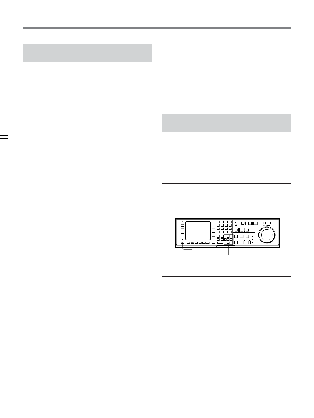
4-2 HOME Menu
4-2-7 Selecting the Capstan Servo Lock Mode (CAP LOCK)
Press the ALT button, then the [F5] (CAP LOCK)
button to select the capstan servo lock mode when you
edit or play a tape with decoded component signals
(i.e., a tape with composite input data recorded on a
Digital Betacam VTR or Betacam/Betacam SP VTR).
DVW-A500/1 and 500/1 only
2FD: The capstan servo is locked every 2 fields.
Since color framing is disabled, phase shifting (Hshifting) of output video signals does not occur
during playback. This is the normal setting for
Chapter 4 Menu Settings
editing or playback of component signals.
To enhance the frequency characteristics, Hshifting of the video output on the basis of the
decoding information on the tape may also be
performed by setting 712. VIDEO PROCESS ON
CAP LOCK 2 FIELD in the VTR SETUP menu.
4FD: The capstan servo is locked to the color frame
every 4 fields. The VTR maintains the phase of
the video output signals even after repeated
stopping and restarting of playback.
Use this setting if you require continuity in video
phase at edit points during editing or playback of
composite signals, or when you perform AB
rolling.
8FD: The capstan servo is locked to the color frame
every 8 fields. The VTR maintains the phase of
the video output signals even after repeated
stopping and restarting of playback.
Use this setting if you require continuity in video
phase at edit points during editing or playback of
composite signals, or when you perform AB
rolling.
4-2-8 Setting the Preroll Time (P-ROLL TIME)
Set the preroll time by pressing the ALT button, then
press the [F6] (P-ROLL TIME) button.
You can set a preroll time of 0 to 30 seconds in 1second units. During editing on this VTR, a preroll
time of 5 seconds or more is recommended.
Setting the preroll time
DVW-A500P/1 and 500P/1 only
2FD: The capstan servo is locked every 2 fields.
Since color framing is disabled, phase shifting (Hshifting) of output video signals does not occur
during playback. This is the normal setting for
editing or playback of component signals.
To enhance the frequency characteristics, Hshifting of the video output on the basis of the
decoding information on the tape may also be
performed by setting 712. VIDEO PROCESS ON
CAP LOCK 2 FIELD in the VTR SETUP menu.
4FD: The capstan servo is locked every 4 fields.
This is the normal setting for editing of
component signals with quick servo lock.
To enhance the frequency characteristics, Hshifting of the video output on the basis of the
decoding information on the tape may also be
performed by setting 712. VIDEO PROCESS ON
CAP LOCK 2 FIELD in the VTR SETUP menu.
1,3
Setting the preroll time
2
1 Press the ALT button, then the [F6] (P-ROLL
TIME) button.
A data entry window appears.
2 Change the setting with the G or g button.
You may also use the + or – button.
3 Press the [F6] (P-ROLL TIME) button.
The data entry window disappears.
4-16 Chapter 4 Menu Settings
Page 53

4-2-9 Selecting DMC Playback (DMC)
4-2-11 Recalling Edit Points (LAST EDIT)
In DMC (Dynamic Motion Control) playback mode,
the VTR plays back a tape segment at a specified
variable speed of –1 to +3 times normal playback
speed, memorizes the speed, then plays the segment
back at a later time at the memorized speed.
DMC playback is useful during on-the-spot telecasts of
sporting events for immediate playback and broadcast
of highlight scenes for which starting and ending
points have been set during recording.
For detail on the procedure for DMC playback, refer to “54-4 DMC Playback” on page 5-10.
During tape editing using two DVW-A500/1 series or
500/1 series VTRs, you can use DMC playback to
control the playback speed of the player VTR for
editing at variable speeds (DMC editing).
For details on DMC editing, refer to “6-2-1 Performing
DMC Editing” on page 6-14.
Selecting DMC playback
While editing, you can recall the last edit points by
pressing the ALT button, then the [F10] (LAST EDIT)
button.
The edit points appear in the display.
DOLBY
NR
CH.COND
DIGITÅL
HOME
BÅSEBÅLL EDIT SET
ƒ
INS
INS
off
INS
CUE
off
Å-CH4
off
Edit points
PRE
REÅD
off
LOCK
TCR PLÅY 4FD F1
CONFI
off
ÅIN 00:00:00:00 ÅOUT 00:00:00:00
ÅSSEM-
IN 00:00:00:00 OUT 00:00:00:00
BLE
off
INS
TC
off
INS
VIDEO
Å-CH1
off
Recalling edit points (LAST EDIT)
GREEN
01Ó04µ58ß00
INS
INS
Å-CH2
off
Å-CH3
off
Chapter 4 Menu Settings
Set 111. PROGRAM PLAY in the VTR SETUP Menu
to disable.
The ALT/[F8] (P-PLAY) button in the display
disappears (only one of either playing modes can be
specified at any time).
4-2-10 Selecting Program
Playback (P-PLAY)
In program playback mode, you can play a tape at a
previously specified speed.
For details on program playback, refer to “5-4-5 Program
Playback” on page 5-13.
Selecting program playback
Set 111. PROGRAM PLAY in the VTR SETUP menu
to enable.
A data entry window appears, and the ALT/[F7]
(DMC) button in the display disappears (only one of
either playing modes can be specified at any time).
Chapter 4 Menu Settings 4-17
Page 54
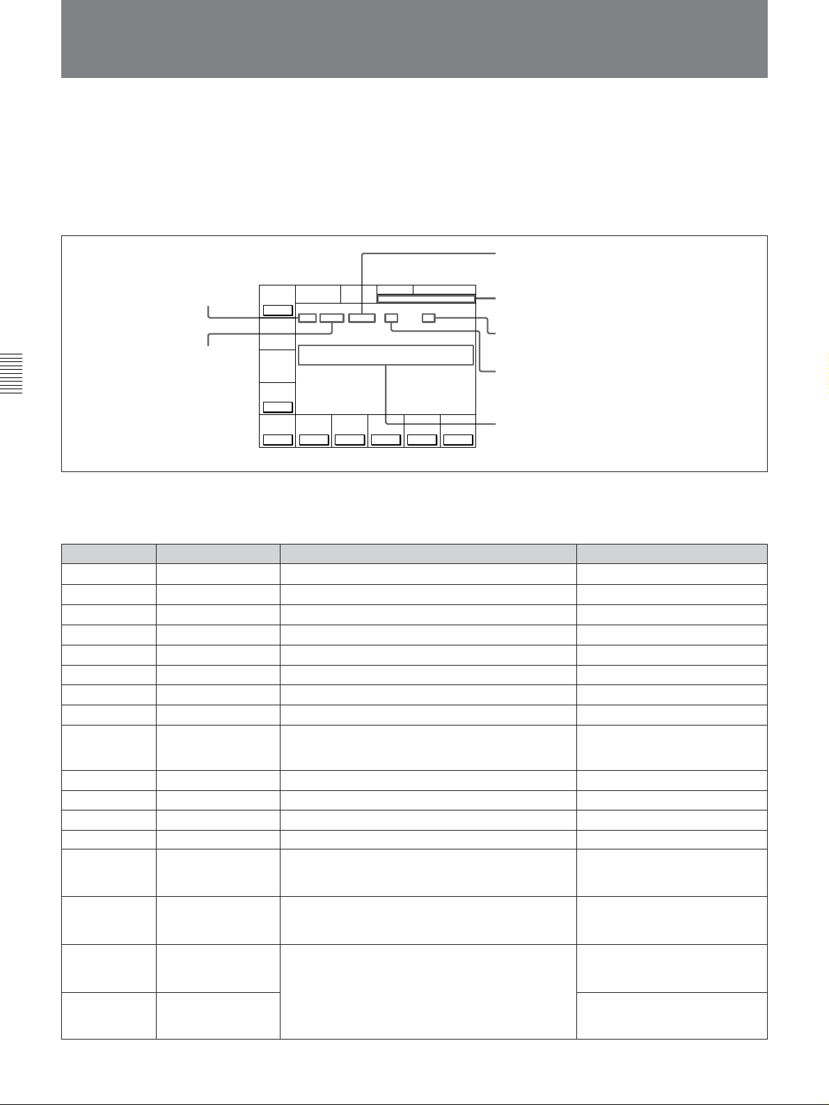
4-3 TC Menu
4-3 TC Menu
The TC menu allows you to set time code-related
items through a single menu.
The HOME, TC, PF1 and PF2 menus show
information that includes the VTR operation mode,
time code of the current position, and the time code
type, etc.
TCR: Time data type
(CTL/TCR/UBR/TCG/UBG/DUR)
VITC: Time code type (LTC/VITC)
Chapter 4 Menu Settings
For details on operation modes, refer to “4-2 HOME
Menu” on page 4-13.
Button
[F1]
[F2]
[F3]
[F4]
[F5]
[F6]
[F7]
[F8]
[F9]
[F10]
ALT/[F1]
ALT/[F2]
ALT/[F6]
ALT/[F7] CHARA H-POS Changes the superimposition position (horizontal).
ALT/[F8] CHARA V-POS Changes the superimposition position (vertical).
ALT/[F9] VITC POS-1
ALT/[F10] VITC POS-2
Indication
TIMER SEL
TIMER RESET
TIMER SET
TIMER HOLD
TC SEL
TCG SOURCE
TCG MODE
RUN MODE
DF/NDF (DVW-
A500/1 and 500/1
only)
VITC
TAPE TIMER
ID PRESET
CHARA SUPER
To activate the TC menu
Press the TC button.
To change the TC menu page
Press the ALT button.
INTRP (interpolation): This appears when time
code cannot be read correctly and correction
DOLBY
NR
CH.COND
TIMER
SEL
TC
LOCK
TCR VITC INTRP DF 4FD F1
TIMER
RESET
01Ó04µ58ß00
ÅIN 00:00:00:00 ÅOUT 00:00:00:00
TIMER
IN 00:00:00:00 OUT 00:00:00:00
SET
TIMER
HOLD
off
TC
TCG
SEL
SOURCE
VITC
int
Information shown in the HOME, TC, PF1 and PF2 menus
GREEN
TCG
MODE
prst
DIGITÅL TC
RUN
DF/NDFDFVITC
MODE
rec
ƒ
on
TC menu
Function
Selects time data type.
Resets the time counter.
Sets the time data.
Holds the time counter.
Sets the time code reader.
Selects the internal/external time code generator.
Sets the time code generator.
Selects the running mode of the time code.
Selects drop frame mode.
Specifies recording of VITC.
Selects the CTL display mode.
Specifies ID preset.
Specifies superimposition of character information.
Specifies the VITC insertion line.
has been performed.
Data entry window
F1: Field number (F1/F2)
DF: This appears when drop frame mode data is
being recorded or played (DVW-A500/1 and
500/1 only).
AIN: Time data for an AUDIO IN point
AOUT: Time data for an AUDIO OUT point
IN: Time data for an IN point
OUT: Time data for an OUT point
Settings
CTL, TC, UBIT
on, off
VITC, AUTO, LTC
int, ext
regen, prst
free, rec
DF, NDF
on, off
+/–12H, 24H
on, off
on, off
0 to 24 (DVW-A500/1 and 500/1)
0 to 22 (DVW-A500P/1 and
500P/1)
0 to 6A (DVW-A500/1 and 500/1)
0 to 81 (DVW-A500P/1 and
500P/1)
12 to 20 (DVW-A500/1 and 500/1)
(9 to 22 (DVW-A500P/1 and
500P/1)
12 to 20 (DVW-A500/1 and 500/1)
(9 to 22 (DVW-A500P/1 and
500P/1)
4-18 Chapter 4 Menu Settings
Page 55
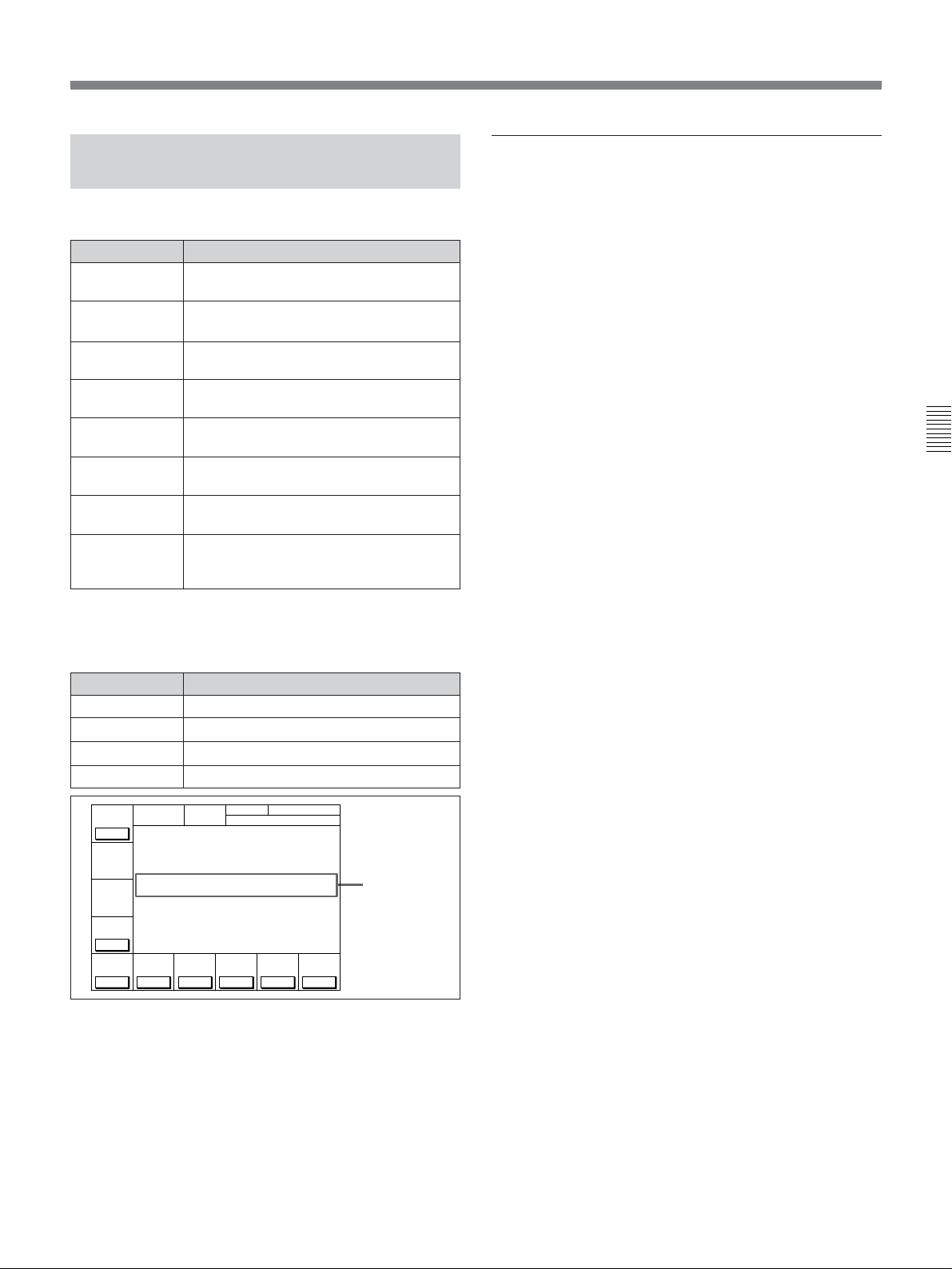
4-3-1 Setting the Time Data (TIMER SEL/RESET/SET/HOLD)
The display shows the following types of time data:
Indication Time data type
TCR LTC
The LTC
reader during playback.
TCR VITC The VITC1) value read by the time code
reader during playback.
TCG
The value generated by the time code
generator during recording.
CTL The number of CTL signals
during recording/playing.
UBR LTC The user bits
code reader (LTC) during playback.
UBR VITC The user bits value read by the time code
reader (VITC) during playback.
UBG
The user bits value generated by the time
code generator during recording.
DUR
Appears whenever a duration between
any two edit points (IN, OUT, AUDIO IN
or AUDIO OUT points) is displayed.
1)
value read by the time code
2)
on the tape
3)
value read by the time
Selecting the time data display
Press the [F1] (TIMER SEL) button repeatedly to
select the desired time data display.
CTL: Counts the CTL signals on the playback tape
or the CTL signals being recorded on the tape, and
displays the tape running time in hours, minutes,
seconds, and frames.
TC: Displays the value read by the time code reader
or the value generated by the time code generator.
To switch between VITC and LTC, press the [F5]
(TC SEL) button.
UBIT: Displays user bits data inserted in time code
being played back, or the user bits data inserted in
time code being recorded. To switch between
VITC and LTC, press the [F5] (TC SEL) button.
Chapter 4 Menu Settings
Time data for IN, OUT, AUDIO IN and AUDIO OUT
points are also displayed.
Indication Time data type
IN Time data for an IN point.
OUT Time data for an OUT point.
AUDIO IN
AUDIO OUT Time data for an AUDIO OUT point.
DOLBY
TIMER
SEL
TC
LOCK
TCR VITC PLAY DF 4FD F1
TIMER
RESET
ÅIN 00:00:00:00 ÅOUT 00:00:00:00
TIMER
IN 00:00:00:00 OUT 00:00:00:00
SET
TIMER
HOLD
off
TC
SEL
SOURCE
VITC
..........................................................................................................................................................................................................
1) LTC and VITC
LTC cannot be read when the tape speed is very slow or
is changed suddenly. VITC, on the other hand, can be
read more accurately than LTC when the VTR is stopped
or the tape speed is very low. VITC, however, cannot be
read when the tape speed is very fast.
Time data for an AUDIO IN point.
NR
CH.COND
DIGITÅL TC
GREEN
01Ó04µ58ß00
ƒ
TCG
TCG
RUN
int
MODE
prst
MODE
rec
DF/NDFDFVITC
on
Time data for
edit points
2) CTL signals
CTL (control) signals are pulse signals that are recorded
horizontally in each frame.
3) User bits
Comprising a part of the time code, user bits record
supplementary information and consist of an eight-digit
number or hexadecimal A to F.
Chapter 4 Menu Settings 4-19
Page 56

4-3 TC Menu
Setting time code
Before starting the procedure below for setting time
data, set the [F6] (TCG SOURCE) button to int, the
[F7] (TCG MODE) button to prst, and the [F10]
(VITC) button to on. When not recording VITC, set
the [F10] (VITC) button to off.
Note
Set the [F8] (RUN MODE) button to rec before setting
the time data for recording. When you select rec, time
data advances from a set value only during recording.
When you select free, time code advances in real time
after the initial value has been set.
Chapter 4 Menu Settings
1342
To cancel entered value
Press the CLR button.
3 Press the SET button to set the entered
value.
If you pressed the + or – button, then entered a
value, the result of calculation appears in the
display.
SET is displayed.
NR
DOLBY
TIMER
SEL
TC
LOCK
TCR VITC PLÅY 4FD F1
TIMER
RESET
ÅIN 00:00:00:00 ÅOUT 00:00:00:00
TIMER
IN 00:00:00:00 OUT 00:00:00:00
SET
TIMER
HOLD
off
TC
SEL
SOURCE
VITC
CH.COND
DIGITÅL
GREEN
TC
SET 01 00 30 00
01Ó 04µ 58ß 00ƒ
TCG
TCG
RUN
int
MODE
prst
MODE
rec
DF/NDFDFVITC
on
4 Press the [F3] (TIMER SET) button.
The input value is set as the time code and appears
in the time data display section.
Setting time code
1 Press the [F1] (TIMER SEL) button to select the
TC (time code) to be set.
2 Enter the new setting in the data entry window
with the numeric buttons.
For example, to enter 01H00M30S00F, press 1, 0,
0, 3, 0, 0, 0. (The leading 0 is not required. When
the entered value is less than eight digits, the
leading digit(s) is (are) set to 0 when you press the
SET button.)
DOLBY
NR
CH.COND
DIGITÅL
TIMER
SEL
TC
LOCK
TCR VITC PLÅY 4FD F1
TIMER
RESET
ÅIN 00:00:00:00 ÅOUT 00:00:00:00
TIMER
IN 00:00:00:00 OUT 00:00:00:00
SET
TIMER
HOLD
off
TC
SEL
SOURCE
VITC
GREEN
01Ó04µ58ß00
TCG
TCG
MODE
int
prst
TC
01 00 30 00
ƒ
RUN
DF/NDFDFVITC
MODE
rec
on
Data entry
window
DOLBY
NR
CH.COND
DIGITÅL
TIMER
SEL
TC
LOCK
TCR VITC PLÅY 4FD F1
TIMER
RESET
ÅIN 00:00:00:00 ÅOUT 00:00:00:00
TIMER
IN 00:00:00:00 OUT 00:00:00:00
SET
TIMER
HOLD
off
TC
SEL
SOURCE
VITC
GREEN
01Ó00µ30ß00
TCG
TCG
MODE
int
MODE
prst
TC
01 00 30 00
ƒ
RUN
DF/NDFDFVITC
rec
on
Notes
•Time code from an external time code generator
cannot be set.
•Time code cannot be set when the internal time code
generator is locked to external time codes or time
codes read by the time code reader.
4-20 Chapter 4 Menu Settings
Page 57

Resetting time data
Press the [F2] (TIMER RESET) button.
The internal time code generator is reset according to
the setting of the [F1] (TIMER SEL) button.
4 When the target time arrives, press the [F3]
(TIMER SET) button.
The time code generator starts operating from the
specified time.
Resetting CTL data
The time data display becomes 00H00M00S00F and
all edit points are erased.
Resetting TC or UBIT data
The internal time code generator is reset and the time
data display becomes 00H00M00S00F (TC) or 00 00
00 00 (UBIT). Edit points are not affected.
Notes
•Time data read by the time code reader cannot be
reset.
•Time data cannot be reset when the internal time code
generator is locked to external time codes or time
codes read by the time code reader.
Setting the user bit value
1 Press the ALT button, then select off by pressing
the [F2] (ID PRESET) button.
2 Press the ALT button again, then select UBIT by
pressing the [F1] (TIMER SEL) button.
3 Enter the desired user bit value in hexadecimal
notation using the numeric buttons.
(Press the 0 to 5 buttons while holding down the
SFT button to enter the letters A to F.)
4 Press the [F3] (TIMER SET) button.
4-3-2 Setting the Time Code Reader (TC SEL)
Press the [F5] (TC SEL) button to select the time code
to be read by the time code reader during playback.
VITC: Reads VITC.
AUTO: Reads VITC when the playback speed is +/
–1/2 times normal speed or less, and LTC when it
is greater than +/–1/2 times normal speed.
LTC: Reads LTC.
Depending on the time code recorded on a tape, VITC
or LTC appears on the display.
Time codes that are read by the time code reader or
played back are output from the TIME CODE OUT
connector.
4-3-3 Setting the Time Code Generator (TCG SOURCE/MODE)
There are two ways to record time codes on the VTR.
One way is to record the output of the VTR’s internal
time code generator. The other is to directly record
time codes that are input from an external time code
generator.
The output from the internal time code generator can
either be set to a specified initial value, or
synchronized with an external time code generator.
Chapter 4 Menu Settings
Recording the current time
1 Select df by pressing the [F9] (DF/NDF) button
(DVW-A500/1 and 500/1 only).
2 Select free by pressing the [F8] (RUN MODE)
button.
3 Enter the target time with the numeric buttons
while verifying the data in the data entry window.
Selecting the time code generator
Press the [F6] (TCG SOURCE) button repeatedly to
select the time code generator.
int: Selects the time code generated by the internal
time code generator.
ext: Selects an external time code input to the TIME
CODE IN connector, or synchronizes the internal
time code generator to an external time code
generator.
Chapter 4 Menu Settings 4-21
Page 58

4-3 TC Menu
Synchronizing the internal time code
generator to an external time code
Make these settings to synchronize the internal time
code generators of multiple VTRs, or to record the
playback time code signal of an external VTR without
waveform attenuation.
1 To synchronize the internal time code generator
to external LTC
Connect the TIME CODE IN connector to an
external time code generator or the time code
output connector of an external VTR.
To synchronize the internal time code generator
Chapter 4 Menu Settings
to VITC of the input video signals
Select the input video signals by pressing the [F1]
(VIDEO IN) button in the PF1 menu.
2 Set the following function buttons as shown below:
[F6] (TCG SOURCE) button: To ext.
[F7] (TCG MODE) button: To regen (regenerate).
[F10] (VITC) button: To on when recording
VITC.
[F5] (TC SEL) button: To LTC when
synchronizing to LTC. Set to VITC when
synchronizing to VITC.
[F6] (TCG
SOURCE) button
ext
ext
int
[F7] (TCG
MODE) button
prst
regen
prst
Settings
Directly records an
external time code.
Records the time code
of the internal time
code generator in
synchronization with
an external time code.
Records the time
codes of the internal
time code generator
from a set value.
To check the running of the internal time code
generator
Press the STOP button to stop the VTR, then press the
REC button.
4-3-4 Selecting the Time Code Running Mode (RUN MODE)
Press the [F8] (RUN MODE) button to select the time
code running mode.
free: The time code advances when the power is on
regardless of the VTR’s operation mode.
rec: The time code advances only during recording.
When the settings have been completed, the
internal time code generator starts operating in
synchronization with the external time code
generator.
The following table shows the conditions specified by
the various settings of the [F6] (TCG SOURCE) and
[F7] (TCG MODE) buttons.
4-3-5 Selecting the Drop Frame Mode (DF/NDF) (DVW-A500/1 and 500/1 only)
Press the [F9] (DF/NDF) button to select the running
mode for the CTL counter and the time code generator.
DF: Drop frame mode
NDF: Non-drop frame mode
Note
1)
(DF is displayed.)
2)
(NDF is displayed.)
When the [F7] (TCG MODE) button is set to regen,
the drop frame mode is inoperative since the time code
generator is synchronized to the playback time code.
..........................................................................................................................................................................................................
1) Drop frame mode
In order to compensate for differences between time
code values from the time code generator and the actual
time, the drop frame mode causes the time code
generator to omit the first two frames (frame 00 and 01)
in each minute except the tenth.
2) Non-drop frame mode
A mode of advancing the time code in such a way that
the difference in frame values between real time and the
time code is neglected. Using this mode produces a
difference of approximately 86 seconds per day between
real time and the time code.
4-22 Chapter 4 Menu Settings
Page 59

4-3-6 Recording VITC (VITC)
Press the [F10] (VITC) button to specify the recording
of VITC.
on: Records VITC generated by the internal time
code generator.
off: Does not record VITC. However, records VITC
inserted in the video input signal.
For details on the VITC insertion line, refer to “4-3-10
Setting the VITC Insertion Line (VITC POS-1/POS-2)” on
page 4-26.
4-3-9 Superimposition of Character Information (CHARA SUPER/H-POS/V-POS)
When you select on by pressing the ALT button and
then the [F6] (CHARA SUPER) button, time data and
operation mode are indicated as character data
superimposed onto the signals output from the
SERIAL V/A OUTPUT 4(SUPER) and VIDEO
OUTPUT COMPOSITE 3(SUPER) connectors.
Contents of superimposed data
4-3-7 Selecting CTL Display Mode (TAPE TIMER)
Press the ALT button, then the [F1] (TAPE TIMER)
button to select a 12-hour or 24-hour clock for the
CTL display.
+/–12H: 12-hour clock
24H: 24-hour clock
4-3-8 ID Preset (ID PRESET)
The presetting of the ID code in non-volatile memory
as user bits data allows you to recall and record it
during later recording sessions.
Press the ALT button, then the [F2] (ID PRESET)
button to select the ID code recording mode.
on: Records the preset ID code as user bits data.
off: Records the user bits set through the control
panel.
1 Types of time data
Time data
2 Drop frame mark of the time
code reader (DVW-A500/1
and 500/1 only)
3 Drop frame mark of the time
code generator (DVW-A500/1
and 500/1 only)
T CR. 2 3 : 59 .40.18
SRHUTTLESTI LL
5 Control VTR
indication
Contents of superimposed data
Chapter 4 Menu Settings
4 Field mark of the
VITC data
*
6 Operation mode
To preset ID code, reset 603. ID CODE PRESET in
the VTR SETUP menu.
Note
The example above shows the factory-set contents of
data.
You can display different time data on the second line
by changing the setting of 005. DISPLAY
INFORMATION SELECT in the VTR SETUP menu.
Chapter 4 Menu Settings 4-23
Page 60
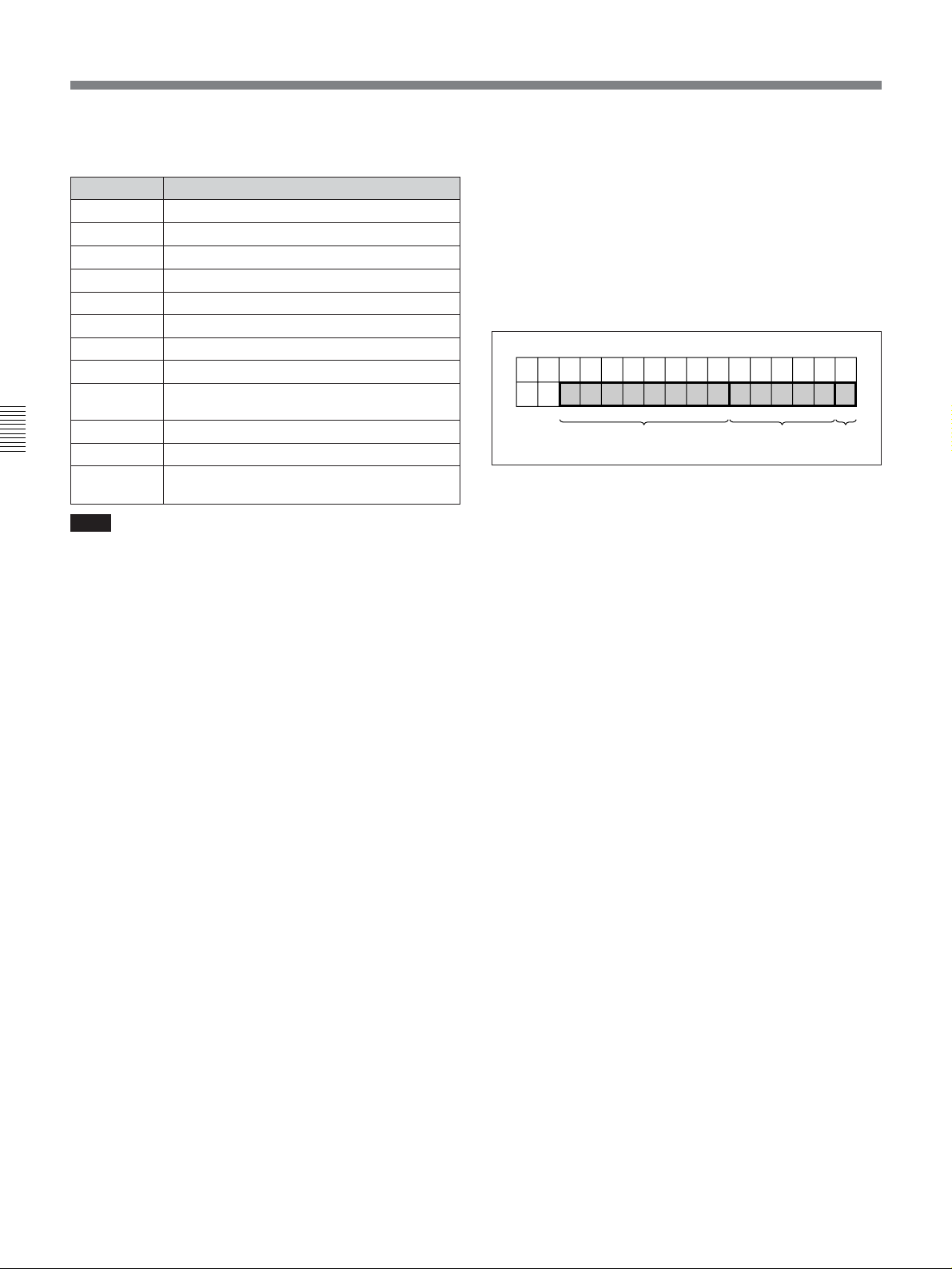
4-3 TC Menu
1Types of time data
Indication Time data
CTL
TCR Time data of the LTC reader
UBR User bits data of the LTC reader
TCR. The time data of the VITC reader
UBR. User bits data of the VITC reader
TCG. Time data of the time code generator
UBG User bits data of the time code generator
IN IN point or starting point of the DMC memory
OUT
AI AUDIO IN point
Chapter 4 Menu Settings
AO
DUR
Note
When a time data or user bits reading error has
occurred, an asterisk (“*”) is displayed where the error
has occurred. For example, “T*R”, “U*R”, “T*R.”, or
“U*R.”.
CTL counter data
OUT point or the ending point of the DMC
memory
AUDIO OUT point
Duration between two points edit (IN, OUT,
AUDIO IN, or AUDIO OUT) points
6 Operation mode
This display is divided into three blocks (A, B, and C),
as shown in the following figure.
Block A: Operation mode
Block B: Servo lock condition or tape speed
Block C: Edit segment during automatic editing, or a
p mark indicating tape speed memorization for
recording/playback in DMC mode
ABC
Operation mode
2 Drop frame mark of the time code reader
(DVW-A500/1 and 500/1 only)
“•”: Drop frame mode (factory-setting)
“:”: Non-drop frame mode
3 Drop frame mark of the time code generator
(DVW-A500/1 and 500/1 only)
“•”: Drop frame mode (factory-setting)
“:”: Non-drop frame mode
4 Field mark of the VITC data
“ ” (blank): Fields 1 and 3 are displayed.
“*”: Fields 2 and 4 are displayed.
5 Control VTR indication
When editing using two VTRs, this indication tells you
which VTR is being controlled by the control panel.
This indication does not appear when two VTRs are
not being used.
R: The VTR control panel controls the recorder VTR
(the RECORDER button on the control panel
lights up).
P: The VTR control panel controls the player VTR
(the PLAYER button on the control panel lights
up).
4-24 Chapter 4 Menu Settings
Page 61

Operation mode display configuration
Block A
TAPE UNTHREAD
Indication
Block B
No cassette is loaded.
Operation mode
STANDBY OFF Standby off mode
T.RELEASE Tension release mode
STOP Stop mode
F.FWD Fast-forward mode
REW Rewind mode
PAUSE Pause mode
PREROLL Preroll mode
PLAY Playback mode (servo unlock)
PLAY LOCK Playback mode (servo lock)
PLAY Deviation (%) from normal
Capstan override mode or program play mode
playback speed
REC Recording mode (servo unlock)
REC LOCK Recording mode (servo lock)
EDIT Edit mode (servo unlock)
EDIT LOCK Edit mode (servo lock)
JOG STILL Still-picture in jog mode
JOG Jog in normal direction (z indicator lights up.)
FWD
JOG REV Jog in reverse direction (Z indicator lights up.)
SHUTTLE (speed) Shuttle mode
VAR (speed) Variable mode
DMC (speed
D-PREV (speed
D-EDIT (speed
a)
) DMC playback mode
a)
) Preview mode during DMC editing
a)
) DMC edit mode
DMC-SPD (speed) During initial speed setting in DMC mode
PLY-SPD Deviation (%) from normal
Tape speed setting for program play
playback speed
PREVIEW Preview mode
AUTO EDIT Automatic edit mode
REVIEW Review mode
Chapter 4 Menu Settings
a) Initial speed or memorized speed
Chapter 4 Menu Settings 4-25
Page 62

4-3 TC Menu
Changing the superimposition position
DVW-A500/1 and 500/1 only
The superimposition position can be moved up to 37
increments (hexadecimal 00 to 24) in the horizontal
direction and up to 106 increments (hexadecimal 00 to
6A) in the vertical direction.
DVW-A500P/1 and 500P/1 only
The superimposition position can be moved up to 35
increments (hexadecimal 00 to 22) in the horizontal
direction and up to 129 increments (hexadecimal 00 to
81) in the vertical direction.
Chapter 4 Menu Settings
1,3
2
4-3-10 Setting the VITC Insertion Line (VITC POS-1/POS-2)
VITC signals can be inserted at two positions between
the 12th line and 20th line (DVW-A500/1 and 500/1)
or between the 9th line and 22nd line (DVW-A500P/1
and 500P/1).
1,3
Setting the VITC insertion line (VITC POS-1/POS-2)
2
1 Press the ALT button, then the [F9] (VITC POS-1)
button.
A data entry window appears.
Changing the superimposition position
1 Press the ALT button and then the [F7] (CHARA
H-POS) button to move the superimposition
position in the horizontal direction, or the [F8]
(CHARA V-POS) button to move it in the vertical
direction.
A data entry window appears.
2 Press the G or g button to change the value.
You can also use the + or – button.
3 Press the [F7] (CHARA H-POS) or [F8] (CHARA
V-POS) button.
The data setting is completed and the data entry
window disappears.
Switching to another menu also completes the data
setting.
2 Press the G or g button to change the value.
You can also use the +or – button.
3 Press the [F9] (VITC POS-1) button.
The data setting is completed and the data entry
window disappears.
Switching to another menu also completes the data
setting.
To place VITC on another position, repeat the
procedure above, pressing the [F10] (VITC POS-2)
button in Steps 1 and 3 instead of the [F9] (VITC
POS-1) button.
4-26 Chapter 4 Menu Settings
Page 63

4-4 CUE Menu
The BKDW-515 allows you to register up to 100 cue
points (0 to 99), and to manage cue points in groups of
10 (per page).
Cue point settings, deletions, and page settings are
done through the CUE menu.
PREV
PÅGE
[I ÅM CUE TITLE ]
NEXT
PÅGE: 0
PÅGE
1
2
3
Page number indication
CUE
P-ROLL
4
5
6
7
8
9
PÅGE
CUE menu display
For details on storing cue point data, refer to “4-1-5 IC
Memory Card Function” on page 4-6.
To activate the CUE menu
Press the CUE button.
CUE
TCR 00:00:00:00
10 00:00:00:00
11 00:00:00:00
12 00:00:00:00
13 00:00:00:00
14 00:00:00:00
15 00:00:00:00
16 00:00:00:00
17 00:00:00:00
18 00:00:00:00
19 00:00:00:00
CUENUM
SET
SET
Data entry window
Title
Cue point indication
Chapter 4 Menu Settings
Button Indication Function
[F1]
[F2]
[F5]
[F8]
[F9]
ALT/[F8]
ALT/[F9]
PREV PAGE Shows the previous page.
NEXT PAGE Shows the next page.
CUE P-ROLL Specifies the preroll time to a cue point.
PAGE SET
Specifies the page number.
CUENUM SET Specifies the cue number.
PAGE MODE Selects PAGE mode.
EXTEND MODE Selects EXTEND mode.
CUE menu
Settings
0 to 30 s
Chapter 4 Menu Settings 4-27
Page 64

4-4 CUE Menu
4-4-1 Selecting a Multi-Cue Mode
The BKDW-515 has the following two multi-cue
modes.
PAGE mode
Press the ALT button, then the [F8] (PAGE MODE)
button.
In PAGE mode, cue point data can be accessed by
page number, thus speeding up cue point registration
and cuing operations.
Display
Chapter 4 Menu Settings
Cue points are displayed in groups of 10, number 0 to
9, 10 to 19, etc. Each display is a page.
Selecting a page
There are the three following ways to select a page:
•Press the [F1] (PREV PAGE) button.
The previous page is shown.
•Press the [F2] (NEXT PAGE) button.
The next page is shown.
•Enter the desired page number with the numeric
button, then press the [F8] (PAGE SET) button.
If you enter 1, for example, page one appears,
containing cue point numbers 10 to 19.
4-4-2 Registering Cue Points
There are two ways to register cue points: (1) by direct
registration of the tape address where the ENTRY
button is pressed, and (2) by the entry of cue point data
with the numeric buttons.
Registering cue points by pressing the
ENTRY button
2
1
Registering cue points by pressing the ENTRY button
5
3
4
1 Press the ALT button, then the [F8] (PAGE
MODE) button or the [F9] (EXTEND MODE)
button.
EXTEND mode
Press the ALT button, then the [F9] (EXTEND
MODE) button.
In EXTEND mode, you can do operations that cannot
be done in page units, such as the consecutive
registration of more than 10 cue points.
Display
The screen displays a list of 100 consecutive cue
points which can be scrolled. Press the G or g button
to scroll the list. Page columns are not displayed.
To quickly scroll a list
Press the G or g button while holding down the SFT
button.
2 If you selected PAGE mode, press the ALT button,
then the [F1] (PREV PAGE) button or [F2] (NEXT
PAGE) button (or use the numeric buttons to enter
the page number in the data entry window, then
press the ALT button again, then the [F8] (PAGE
SET) button).
3 Press the G or g button to move the cursor (z) to
the cue number to be registered.
PREV
PÅGE
[I ÅM CUE TITLE ]
NEXT
PÅGE: 0
PÅGE
CUE
P-ROLL
1
2
3
4
5
6
7
8
9
PÅGE
10 00:00:00:00
11 00:00:00:00
12 00:00:00:00
13 00:00:00:00
14 00:00:00:00
15 00:00:00:00
16 00:00:00:00
17 00:00:00:00
18 00:00:00:00
19 00:00:00:00
CUE
TCR 00:00:00:00
CUENUM
SET
SET
4-28 Chapter 4 Menu Settings
Page 65

To select the cue number directly by
numeric buttons
Enter the cue number in the data entry window
with the numeric buttons, then press the [F9]
(CUENUM SET) button.
4 Press the JOG or VAR button, then rotate the
search dial to find the position where you want to
register the cue point.
5 Press the ENTRY button at the selected position.
The current tape address of the position where the
button is pressed is registered as a cue point.
Press the ENTRY button repeatedly to register the
cue point repeatedly. The cue number will
automatically increment by one each time.
Registering cue points by the numeric
buttons
24
1
Registering cue points by the numeric buttons
5
3
Chapter 4 Menu Settings
PREV
PÅGE
[I ÅM CUE TITLE ]
NEXT
PÅGE: 0
PÅGE
CUE
P-ROLL
1
2
3
4
5
6
7
8
9
PÅGE
10 00:00:00:00
11 00:00:00:00
12 00:00:00:00
13 00:00:00:00
14 00:00:00:00
15 00:00:00:00
16 00:00:00:00
17 00:00:00:00
18 00:00:00:00
19 00:00:00:00
CUE
TCR 01:00:30:00
CUENUM
SET
SET
Note
In PAGE mode, each time you press the ENTRY
button to register a cue point more than once, the cue
number automatically increments on the page. For
example, after registering cue point No. 19 on page 1,
the next cue point is registered to cue point No.10. In
EXTEND mode, if you press the ENTRY button after
registering, for example, cue point No.99, the next cue
point is registered to cue point No.99 again.
1 Press the ALT button, then the [F8] (PAGE
MODE) button or the [F9] (EXTEND MODE)
button.
2 If you selected PAGE mode, press the ALT button,
then the [F1] (PREV PAGE) button or [F2] (NEXT
PAGE) button (or use the numeric buttons to enter
the page number in the data entry window, then
press the [F8] (PAGE SET) button).
3 Press the G or g button to move the cursor (z) to
the cue number to be registered.
PREV
PÅGE
[I ÅM CUE TITLE ]
NEXT
PÅGE: 0
PÅGE
CUE
P-ROLL
1
2
3
4
5
6
7
8
9
PÅGE
10 00:00:00:00
11 00:00:00:00
12 00:00:00:00
13 00:00:00:00
14 00:00:00:00
15 00:00:00:00
16 00:00:00:00
17 00:00:00:00
18 00:00:00:00
19 00:00:00:00
CUE
TCR 00:00:00:00
CUENUM
SET
SET
To select the cue number directly by the
numeric buttons
Enter the cue number in the data entry window
with the numeric buttons, then press the [F9]
(CUENUM SET) button.
Chapter 4 Menu Settings 4-29
Page 66

4-4 CUE Menu
4 Enter the cue point data in the data entry window
with the numeric buttons, then press the SET
button.
For example, to enter 01:30:00:00, press 1, 3, 0, 0,
0, 0, 0. (The leading 0 is not required. When the
entered value is less than eight digits, the leading
digit(s) is (are) set to 0 when you press the SET
button.)
PREV
PÅGE
NEXT
PÅGE
Chapter 4 Menu Settings
CUE
P-ROLL
To modify current cue point data
Press the + or – button, enter the value to be added
or subtracted, then press the SET button. The
computation is performed and the results appear in
the data entry window.
5 Press the ENTRY button to set the entered data.
The data are registered in the cue point data
indication.
[I ÅM CUE TITLE ]
PÅGE: 0
1
2
3
4
5
6
7
8
9
PÅGE
10 00:00:00:00
11 00:00:00:00
12 00:00:00:00
13 00:00:00:00
14 00:00:00:00
15 00:00:00:00
16 00:00:00:00
17 00:00:00:00
18 00:00:00:00
19 00:00:00:00
CUE
SET 01 00 30 00
TCR 00:00:00:00
CUENUM
SET
SET
4-4-3 Erasing Cue Point Data
To erase any cue point data, blank out the data entry
window, then do the cue point registration procedure.
2
Entered data
1
Erasing cue point data
5
4
3
1 Press the ALT button, then the [F8] (PAGE
MODE) button or the [F9] (EXTEND MODE)
button.
2 If you selected PAGE mode, press the ALT button,
then the [F1] (PREV PAGE) button or [F2] (NEXT
PAGE) button (or use the numeric buttons to enter
the page number in the data entry window, then
press the [F8] (PAGE SET) button).
3 Press the G or g button to move the cursor (z) to
the cue number to be erased.
PREV
PÅGE
[I ÅM CUE TITLE ]
NEXT
PÅGE: 0
PÅGE
1
2
3
4
5
6
7
8
9
CUE
P-ROLL
PÅGE
4-30 Chapter 4 Menu Settings
CUE
TCR 00:00:00:00
10 00:00:00:00
11 01:00:30:00
12 00:00:00:00
13 00:00:00:00
14 00:00:00:00
15 00:00:00:00
16 00:00:00:00
17 00:00:00:00
18 00:00:00:00
19 00:00:00:00
CUENUM
SET
SET
PREV
PÅGE
[I ÅM CUE TITLE ]
NEXT
PÅGE: 0
PÅGE
1
2
3
4
5
6
7
8
9
CUE
P-ROLL
PÅGE
10 00:00:00:00
11 01:00:30:00
12 00:00:00:00
13 00:00:00:00
14 00:00:00:00
15 00:00:00:00
16 00:00:00:00
17 00:00:00:00
18 00:00:00:00
19 00:00:00:00
CUE
TCR 00:00:00:00
CUENUM
SET
SET
To select the cue number directly by
the numeric buttons
Enter the cue number in the data entry window
with the numeric buttons, then press the [F9]
(CUENUM SET) button.
Page 67

4 Press the CLR button then the SET button.
“SET” appears in a blank data entry window.
4-4-4 Prerolling to a Cue Point
PREV
PÅGE
[I ÅM CUE TITLE ]
NEXT
PÅGE: 0
PÅGE
CUE
P-ROLL
1
2
3
4
5
6
7
8
9
PÅGE
10 00:00:00:00
11 00:00:00:00
12 00:00:00:00
13 00:00:00:00
14 00:00:00:00
15 00:00:00:00
16 00:00:00:00
17 00:00:00:00
18 00:00:00:00
19 00:00:00:00
CUE
SET
TCR 00:00:00:00
CUENUM
SET
SET
Data entry
window
5 Press the ENTRY button.
Data for the specified cue number are erased and
the data column becomes blank.
PREV
PÅGE
[I ÅM CUE TITLE ]
NEXT
PÅGE: 0
PÅGE
CUE
P-ROLL
1
2
3
4
5
6
7
8
9
PÅGE
10 00:00:00:00
11
12 00:00:00:00
13 00:00:00:00
14 00:00:00:00
15 00:00:00:00
16 00:00:00:00
17 00:00:00:00
18 00:00:00:00
19 00:00:00:00
To erase all cue point data
Press the CLR button while holding down the SFT
button. A message asking you to confirm the
operation appears in the display. In EXTEND
mode, press the CLR button while holding down
the SFT button again to erase all data for cue
points No. 0 to No. 99. In PAGE mode, press the
CLR button while holding down the SFT button
again to erase data for the cue points on the current
page.
CUE
TCR 00:00:00:00
CUENUM
SET
SET
Erased cue point
Set the [F5] (CUE P-ROLL) button to specify the
preroll time to a cue point.
You can set a preroll time of 0 to 30 seconds in 1second units.
Prerolling to a cue point
2
1
Prerolling to a cue point
34
1 Press the ALT button, then the [F8] (PAGE
MODE) button or the [F9] (EXTEND MODE)
button.
2 If you selected PAGE mode, press the ALT button,
then the [F1] (PREV PAGE) button or [F2] (NEXT
PAGE) button (or use the numeric buttons to enter
the page number in the data entry window, then
press the [F8] (PAGE SET) button).
3 Press the G or g button to move the cursor (z) to
the cue number.
To select the cue number directly by the
numeric buttons
Enter the cue number in the data entry window
with the numeric buttons, then press the [F9]
(CUENUM SET) button.
Chapter 4 Menu Settings
4 Press the PREROLL button.
Chapter 4 Menu Settings 4-31
Page 68

4-4 CUE Menu
4-4-5 Changing a Cue Point Into an Edit Point
Follow the procedure below to change any cue point
into an edit point.
To change an edit point into an IN point
Press the SET button while hoding down the IN
button.
To change an edit point into an OUT point
Press the SET button while holding down the OUT
button.
Chapter 4 Menu Settings
To change an edit point into an AUDIO IN
point
Press the SET button while holding down the AUDIO
IN button.
To change an edit point into an AUDIO OUT
point
Press the SET button while holding down the AUDIO
OUT button.
4-4-6 Backspace Editing
You can perform backspace editing with the CUE
menu. In backspace editing, assemble editing is
performed from the recording end point. Since the
data specifying recording end point are cleared when
you eject the tape, after inserting a tape, you must
record for at least one minute or so on the tape before
you can do backspace editing. After recording, the
present end of the recorded position becomes the
recording end point. When you press the AUTO
EDIT button afterwards, the VTR automatically
prerolls a few seconds before the recording end point
and starts assemble editing. If no data for the
recording end point exist, backspace editing is not
performed.
AUDIO IN button
IN button
OUT button
AUDIO OUT button
SET button
4-32 Chapter 4 Menu Settings
Page 69

4-5 PF1 Menu (Factory Settings)
Chapter 4 Menu Settings
The PF (Personal Function) 1 menu is used to register
frequently used menu items.
When shipped from the factory, the PF1 menu contains
the adjustment menu for video signals. If you later use
the PF1 menu to register items from other menus, you
can restore the PF1 menu to its original factory settings
by recalling SETUP BANK [F] from the VTR memory
banks.
DOLBY
NR
VIDEO
IN
sif
OUT
REF
ref
PROC
CONTRL
rmt
VIDEO
GÅIN
prst
CHROMÅ
GÅIN
prst
CH.COND DIGITÅL PF1
LOCK
TCR PLÅY 4FD F1
00Ó00µ00ß00
ÅIN --:--:--:-- ÅOUT --:--:--:- IN --:--:--:-- OUT --:--:--:--
SETUP
Y/C
LEVEL
DELÅY
prst
prst
For details on registration methods, refer to “4-1-3
Registering Items to the PF1/2 Menus” on page 4-3, and on
restoring factory-set menu items, refer to “4-1-4 VTR
Memory Bank Function” on page 4-4.
To activate the PF1 menu screen
Press the PF1 button.
ƒ
CHROMÅ
SYSTEM
SYNC
prst
SYSTEM
SC
prst
PHÅSE
prst
Chapter 4 Menu Settings
PF1 menu display
PF1 menu (factory settings)
Button Indication Settings
[F1] Selects the input video signal. sif, cmpst, y-r/b
[F2]
[F3] Switches the control of the digital video processor. menu, local, rmt
[F4] Adjusts the output level of the video output signal.
[F5] Adjusts the chroma output level. prst, 0 to B50H
[F6] Adjusts the setup level. prst, 0 to 220H
VIDEO IN
OUT REF
PROC CONTRL
VIDEO GAIN
CHROMA GAIN
SETUP LEVEL (DVW-
Function
Selects the reference signal for output. ref, input
prst, 0 to B50H
A500/1 and 500/1 only)
BLACK LEVEL (DVW-
Adjusts the black level.
prst, 0 to 220H
A500P/1 and 500P/1 only)
[F7]
Y/C DELAY(DVW-A500/1
Adjusts the Y/C delay during analog Betacam playback. prst, 0 to FFFH
series only)
[F8] Adjusts the chroma phase. prst, 0 to FFHCHROMA PHASE
[F9]
SYSTEM SYNC
Adjusts the system sync phase. prst, 0 to FFH
[F10] Adjusts the system sub-carrier phase. prst, 0 to 3FFHSYSTEM SC
Chapter 4 Menu Settings 4-33
Page 70

4-5 PF1 Menu (Factory Settings)
Press the [F1] (VIDEO IN) button repeatedly to select
the video signal to input.
Chapter 4 Menu Settings
Press the [F2] (OUT REF) button to select the signal to
be used as the reference signal for VTR operations.
4-5-1 Selecting the Input Video Signal (VIDEO IN)
sif: Serial digital video signal input to the SERIAL V/
A INPUT connector
cmpst: Analog composite video signal input to the
COMPOSITE VIDEO INPUT connector
y-r/b: Analog component video signal input to the
COMPONENT VIDEO INPUT connectors
4-5-2 Selecting the Reference Signal (OUT REF)
ref: The signal input to the REF.VIDEO INPUT
connector is used as the reference signal for
playback and audio recording. Digital audio and
video input signals must synchronize with this
reference signal during recording.
input: The video input signal is used as the reference
signal for VTR operations. The [F1] (VIDEO IN)
button switches the video input signal.
Note
Changing the PROC CONTRL setting during playback
may cause a momentary interruption in the sound
output.
4-5-4 Adjusting the Output Video Signal (VIDEO GAIN to SYSTEM SC)
Adjusting the output video signal
Follow the procedure below to adjust the output video
signal.
1,3
1,3
2
4-5-3 Switching the Control of the Digital Video Processor (PROC CONTRL)
Press the [F3] (PROC CONTRL) button to select the
method for operating the internal digital video
processor.
menu: Select this setting when adjusting the settings
of the internal digital video processor through the
PF1 menu or items 715 to 721 of the VTR SETUP
menu.
local: Select this setting when controlling the
internal digital processor from the control panel of
the VTR.
rmt: Select this setting when using the optional
BVR-50 Remote Controller to remotely control
the internal digital video processor.
For details on items 715 to 721 of the VTR SETUP menu,
refer to Menu List on page A-28.
Adjusting the output video signal
1 Press the function button ([F4] to [F10]) whose
setting you wish to set.
The setting display section lights up.
2 Change the numerical value by pressing the G or
g button (or + or – button).
To change the value quickly, press the buttons
while holding down the SFT button.
To set the preset value
Press the center cursor button.
PRST appears over the respective function button.
3 Press the function button after adjusting the
numerical value.
4-34 Chapter 4 Menu Settings
Page 71

Adjusting the output level
Make this adjustment with the [F4] (VIDEO GAIN)
button.
prst: Selects the standard setting.
Numerical value: 0 to B50H
Adjustable range: –3 to +3 (dB)
The range of the numerical value may be adjusted
through 714. VIDEO ADJUST RANGE of the VTR
SETUP menu. The range is ±3 dB when controlling
the VTR from a device (such as a BVR-50) connected
to the VIDEO CONTROL connector in the connector
panel.
Adjusting the chroma output level
Make this adjustment with the [F5] (CHROMA GAIN)
button.
prst: Selects the standard setting.
Numerical value: 0 to B50H
Adjustable range: –3 to +3 (dB)
The range of the numerical value may be adjusted
through 716. CHROMA GAIN of the VTR SETUP
menu. The range is ±3 dB when controlling the VTR
from a device (such as a BVR-50) connected to the
VIDEO CONTROL connector in the connector panel.
Adjusting the setup level/black level
DVW-A500/1 and 500/1 only
Adjust the setup level with the [F6] (SETUP LEVEL)
button.
prst: Selects the standard setting.
Numerical value: 0 to 220H
Adjustable range: –30 to +30 (IRE)
DVW-A500P/1 and 500P/1 only
Adjust the black level with the [F6] (BLACK LEVEL)
button.
prst: Selects the standard setting.
Numerical value: 0 to 220H
Adjustable range: –210 to +210 (mV)
Adjusting the Y/C delay during analog
Betacam playback (DVW-A500/1 series
only)
Make this adjustment with the [F7] (Y/C DELAY)
button.
prst: Selects the standard setting.
Numerical value: 0 to FFFH
Adjustable range: –100 to +100 (ns)
Adjusting the chroma phase
Set the hue (the relative phase between burst and
chroma) with the [F8] (CHROMA PHASE) button.
prst: Selects the standard setting.
Numerical value: 0 to FFH
Adjustable range: –30 to +30 ( ˚ )
Adjusting the system synchronization
phase
Make this adjustment to match the output phase of the
VTR precisely to that of the reference signal, or to
create special effects as fading, wrapping, and
dissolving through connection with a switcher, and in
conjunction with other VTRs.
The [F9] (SYSTEM SYNC) button sets the sync phase
of the output signal relative to the reference signal
input to the VTR.
prst: Selects the standard setting.
Numerical value: 0 to FFH
Adjustable range: –15 to +15 (µs)
Adjusting the system sub-carrier phase
Make this adjustment to precisely match the output
phase of the VTR relative to the phase of the reference
signal with the level of the sub-carrier phase during
editing using composite signals. This adjustment
keeps the SCH (Sub-Carrier Sync) phase of the output
constant.
The [F10] (SYSTEM SC) button sets the sync and subcarrier phases of the output signal relative to the
reference signal input to the VTR.
prst: Selects the standard setting.
Numerical value: 0 to 3FFH
Adjustable range: –200 to +200 (ns)
Chapter 4 Menu Settings
Chapter 4 Menu Settings 4-35
Page 72

4-6 PF2 Menu (Factory Settings)
4-6 PF2 Menu (Factory Settings)
The PF2 menu is used to register frequently used menu
items.
When shipped from the factory, the PF2 menu contains
the adjustment menu for audio signals. If you later use
the PF2 menu to register items from other menus, you
can restore the PF2 menu to its original factory settings
by recalling SETUP BANK [F] from the VTR memory
banks.
Chapter 4 Menu Settings
For details on registration methods, refer to “4-1-3
Registering Items to the PF1/2 Menus” on page 4-3, and on
restoring factory-set menu items, refer to “4-1-4 VTR
Memory Bank Function” on page 4-4.
To activate the PF2 menu screen
Press the PF2 button.
DOLBY
NR
Å-IN
CH1
sif
Å-IN
CH2
sif
Å-IN
CH3
sif
Å-IN
CH4
sif
CH.COND DIGITÅL PF2
LOCK
TCR PLÅY 4FD F1
00Ó00µ00ß00
ÅIN --:--:--:-- ÅOUT --:--:--:- IN --:--:--:-- OUT --:--:--:--
DOLBY
EMPHÅ-
NR
SIS
on
off
MON-L
SEL
1____
ƒ
MON-R
SEL
1____
PF2 menu display
PF2 menu (factory settings)
Button Function Settings
[F1]
[F2]
[F3]
[F4]
Indication
A-IN CH1
A-IN CH2
A-IN CH3
A-IN CH4
Selects the audio input signal for audio channel 1.
Selects the audio input signal for audio channel 2.
Selects the audio input signal for audio channel 3.
Selects the audio input signal for audio channel 4.
sif, aes/ebu, analg
sif, aes/ebu, analg
sif, aes/ebu, analg
sif, aes/ebu, analg
[F5]
[F6] Sets the Dolby NR
DOLBY NR (DVW-
1)
. on, off
A500/1 series only)
[F7]
[F9]
[F10]
EMPHASIS
MON-L SEL
MON-R SEL
Sets the emphasis.
Selects the monitor output signal for channel L.
Selects the monitor output signal for channel R.
off, on
1, 2, 3, 4, 5
1, 2, 3, 4, 5
..........................................................................................................................................................................................................
1) Dolby NR (Noise Reduction)
Dolby noise reduction manufactured under license from
Dolby Laboratories Licensing Corporation. “DOLBY”
and the double-D symbol a are trademarks of Dolby
Laboratories Licensing Corporation.
4-36 Chapter 4 Menu Settings
Page 73

4-6-1 Selecting the Audio Input Signal (A-IN ALL to A-IN CH4)
Function buttons [F1] (A-IN CH1) to [F4] (A-IN CH4)
select the audio input signal for the various channels.
sif: Selects the audio signal input through the
SERIAL V/A INPUT connector.
aes/ebu: Selects the audio signal input through the
AUDIO INPUT (AES/EBU) connectors.
analg: Selects the audio signal input through the
ANALOG AUDIO INPUT connectors.
4-6-4 Selecting the Monitor
Output Signal (MON-L SEL/MONR SEL)
The [F9] (MON-L SEL) and [F10] (MON-R SEL)
buttons allow you to specify the audio channel to be
output from the left and right MONITOR OUTPUT
connectors, respectively.
1: Audio channel 1
2: Audio channel 2
3: Audio channel 3
4: Audio channel 4
5: Analog cue channel
4-6-2 Setting the Dolby NR System (DOLBY NR) (DVW-A500/ 1 Series Only)
The Dolby NR (noise reduction) C system, which is
used for cue audio tracks, can be turned on or off only
when using an oxide tape. The system automatically
turns on when using a metal tape. Press the [F6]
(DOLBY NR) button to change the DOLBY NR
setting.
on: Select this setting to play an analog Betacam
oxide tape with the Dolby NR system.
off: Select this setting to play an analog Betacam
oxide tape without the Dolby NR system.
4-6-3 Setting Emphasis (EMPHASIS)
To emphasize to a digital audio signal that has been
converted from an analog audio input signal, set the
[F7] (EMPHASIS) button to on.
This setting also allows you to emphasize while
digitizing a playback audio signal from a conventional
Betacam cassette.
When multiple channels are selected for a single
connector, all of the numbers are displayed.
Select the output signal to be monitored as follows:
1 Press the [F9] (MON-L SEL) or [F10] (MON-R
SEL) button. The setting display section lights up.
2 Press numeric buttons 1 to 4 to select audio
channels 1 to 4, or numeric button 5 for the analog
cue channel.
Example: Pressing numeric buttons 1 and 2 selects
audio channels 1 and 2, leaving audio channels 3
and 4, and the analog cue channel off.
“12...” appears in the display.
3 To set the entered audio channels, press the
respective function button ([F9] or [F10]).
Chapter 4 Menu Settings
Chapter 4 Menu Settings 4-37
Page 74

4-7 SET UP Menu
4-7 SET UP Menu
In the SET UP menu, you can store and recall menu
settings to and from the VTR memory banks and IC
memory card, register items to the PF menu, and set
items in the VTR SETUP menu and PANEL SETUP
menu.
For details on storing and recalling data to or from the VTR
memory banks or IC memory card, and registering items to
the PF menus, refer to “4-1 Registering and Storing Menu
Settings” on page 4-1.
Chapter 4 Menu Settings
“$” indicates that more than
one menu page exists.
CH.COND ÅNÅLOG
VTR
BÅNK
MEMORY
CÅRD
PF1&2
ÅSSIGN
PÅNEL
SETUP
VTR BÅNK: Copy data between
[F1]
current setup and 8 banks.
MEMORY CÅRD: Copy data
[F2]
between VTR and memory card.
[F4]
PF1&2 ÅSSIGN: Åssign PF1/PF2
menu function keys.
PÅNEL SETUP: Panel setting
[F5]
[F6]
VTR SETUP: VTR current setup
VTR
SETUP
To activate the SET UP menu
Press the SET UP button.
To change the SET UP menu page
Press the ALT button.
SETUP
current setup name
TCR 00:00:04:10
SETUP MENU
REMOTE
REMOTE
9-PIN
off off
50-PIN
SET UP menu display
SET UP menu
Button
[F1]
[F2]
Indication
VTR BANK
MEMORY CARD
[F4] PF1&2 ASSIGN
[F5]
[F6]
[F8]
PANEL SETUP
VTR SETUP
REMOTE 9-PIN
Function
Refer to “4-1-4 VTR Memory Bank Function” on page 4-4.
Refer to “4-1-5 IC Memory Card Function” on page 4-6.
Refer to “4-1-3 Registering Items to the PF1/2 Menus” on page 4-3.
Refer to “4-7-2 PANEL SETUP Menu” on page 4-42.
Refer to “4-7-1 VTR SETUP Menu” on page 4-40.
Selects remote operation through a device connected to the REMOTE1-
Settings
on, off
IN(9P)/OUT(9P) connectors.
[F9]
REMOTE 50-PIN
Selects remote operation using a device (optional BKDW-509)
on, off
connected to the REMOTE PARALLEL I/O(50P) connector.
ALT/[F9]
ALT/[F10] VIDEO SG on, off
AUDIO SG
Sets the audio test signal.
Sets the video test signal.
on, off
4-38 Chapter 4 Menu Settings
Page 75

Selecting remote operation mode
When operating the VTR with an external device, set
the [F8] (REMOTE 9-PIN) button or [F9] (REMOTE
50-PIN) button to on.
When the [F8] (REMOTE 9-PIN) button is set to
on
You can operate the VTR with a device connected to
the REMOTE1-IN(9P)/OUT(9P) connectors.
When the [F9] (REMOTE 50-PIN) button is set
to on
You can operate the VTR with a device (optional
BKDW-509) connected to the REMOTE PARALLEL
I/O(50P) connector.
Note
When operating the VTR through an external device,
all of the tape operation and editing buttons are
disabled, with the exception of the STOP and EJECT
buttons. You may also set the VTR so that all buttons
are enabled or disabled. Perform this setting through
006. LOCAL FUNCTION ENABLE of the VTR
SETUP menu. You cannot, however, disable the menu
and remote operation mode selection buttons.
Chapter 4 Menu Settings
Setting the test signal
To turn on the internal test signal generator, press the
ALT button, then set the [F9] (AUDIO SG) button to
on, or press the ALT button, then set the [F10]
(VIDEO SG) button to on.
Select the audio test signal through 808. INTERNAL
AUDIO SIGNAL GENERATOR and the video test
signal through 710. INTERNAL VIDEO SIGNAL
GENERATOR in the VTR SETUP menu.
Note
Setting the test signal to OFF in item 710 or 808 in the
VTR SETUP menu turns off the [F9] (AUDIO SG)
button or [F10] (VIDEO SG) button, respectively.
To turn on the test signal generator, select the test
signal on respective item again, turning on the [F9]
(AUDIO SG) button or [F10] (VIDEO SG) button.
Chapter 4 Menu Settings 4-39
Page 76
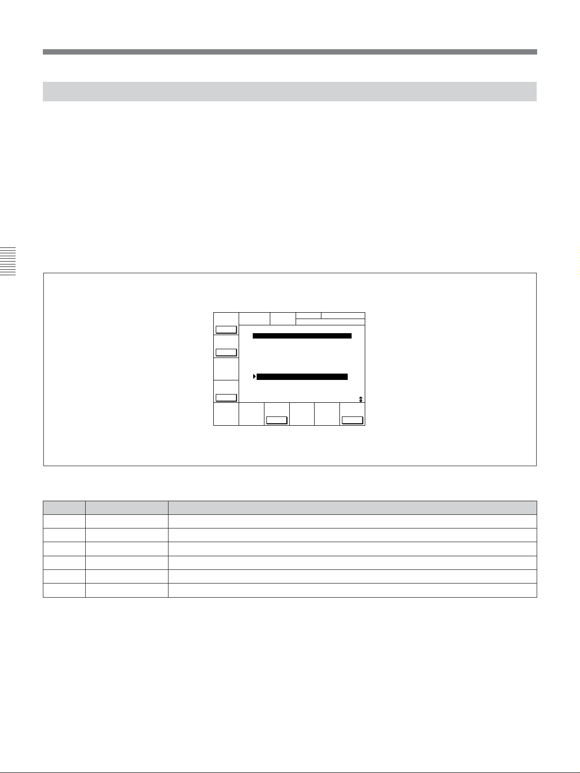
4-7 SET UP Menu
4-7-1 VTR SETUP Menu
All menu items required for setting up the VTR
operating conditions are displayed in the scrollable
VTR SETUP menu.
Items which are frequently used can be registered in
the PF1/2 menus. Those items that can be registered in
a PF menu are displayed in the scrollable PF1&2
ASSIGN menu.
For details on the VTR SETUP menu items, refer to “Menu
List” on page A-7.
For details on registering items to the PF1/2 menus, refer to
“4-1-3 Registering Items to the PF1/2 Menus” on page 4-3.
Chapter 4 Menu Settings
PREV
CÅTEG
NEXT
CÅTEG
MULTI
LOOP
OFF
CURRENT SETUP MENU
603:ID CODE SET - Djs
605:TCG REGEN - TC&UB
606:TC OUT SIG. - Tape
607:BINÅRY GP - 000
608:PHÅSE CORR. - off
609:TCG CF FLÅG - off
610:REGEN MODE - as&in
611:TC RGN SRC - LTC
701:EE DELÅY - as&in
703:BLÅNK LINE
704:DEC MODE
CHÅNGE
DÅTÅ
To activate the VTR SETUP menu
Press the SET UP button, then press the [F6] (VTR
SETUP) button.
VTR SETUP
BÅSEBÅLL EDIT
TCR 00:00:00:00
SÅVE/
EXIT
Button
[F1]
[F2]
[F4]
[F7]
Indication Function
PREV CATEG Move to the beginning of the previous category.
NEXT CATEG Move to the beginning of the next category.
MULTI LOOP Multi-loop
CHANGE DATA Changes the setting.
[F9]
[F10]
SAVE/EXIT Sets the value and exits the VTR SETUP menu.
4-40 Chapter 4 Menu Settings
VTR SETUP menu display
VTR SETUP menu
Page 77
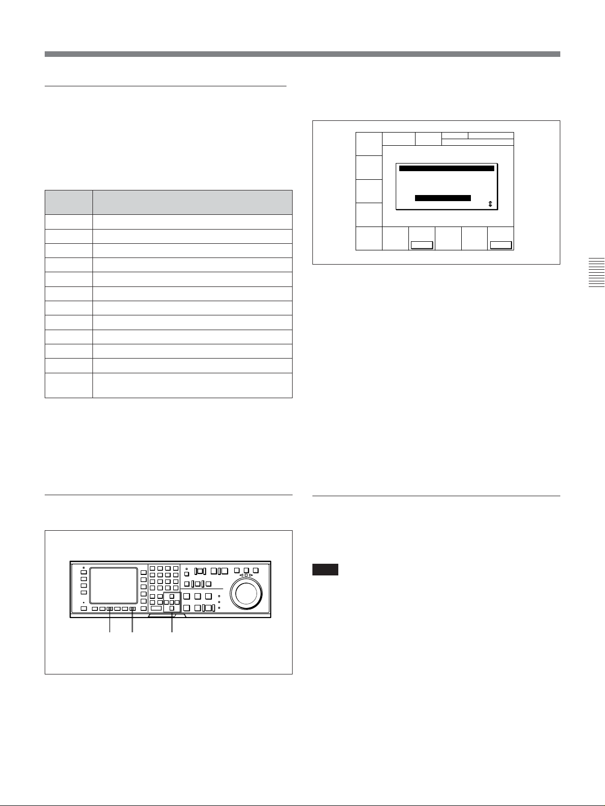
Scrolling items in the VTR SETUP menu
Press the G and g to scroll the items in the VTR
SETUP menu.
To search the menu by category
Items in the VTR SETUP menu are divided into
Menu
number
Hs
000s Items related to VTR operations
100s Items related to operation panels
200s
300s Items related to editing
400s Items related to prerolling
500s Items related to recording protection
600s Items related to the time code generator
700s Items related to the video control
800s Items related to the audio control
900s Items related to digital process
Ks
Category
Items related to the hours meter
Items related to remote interface
Items set by switches on models DVW-A500,
A500P, 500, and 500P
2 Press the [F7] (CHANGE DATA) button.
The window for changing settings appears.
CURRENT SETUP ITEM-610
REGEN ÅUTO MODE
assem & insert
CHÅNGE
DÅTÅ
SÅVE/
EXIT
3 Press the [F7] (CHANGE DATA) button
repeatedly to select the new setting.
When sub-items appear, change the setting as
required with the G or g button, then press the
[F7] (CHANGE DATA) button repeatedly.
4 Press the [F10] (SAVE/EXIT) button.
The new value is set and the window for changing
settings disappears.
Chapter 4 Menu Settings
categories according to type of settings they perform.
Pressing the [F1] (PREV CATEG) button selects the
first item of the previous category.
Pressing the [F2] (NEXT CATEG) button selects the
first item of the next category.
Changing settings
412,3
Changing settings
1 Press the G or g button to move the cursor (z) to
the item to be changed.
5 Repeat Steps 1 to 4 to change more settings.
6 Press the [F10] (SAVE/EXIT) button again.
The new settings are saved and the SETUP menu
display appears again.
To activate the multi-loop function
Press the [F4] (MULTI LOOP) button repeatedly to
select the setting.
Note
The [F4] (MULTI LOOP) button is operative only
when the cursor is positioned on a 700s item (related
to the video control) in the VTR SETUP menu.
The muti-loop function is automatically cancelled
when the control panel exits the VTR SETUP menu.
Chapter 4 Menu Settings 4-41
Page 78

4-7 SET UP Menu
4-7-2 PANEL SETUP Menu
The PANEL SETUP menu is used to set the operation
conditions of the upper and lower control panels.
Chapter 4 Menu Settings
DOLBY NR CH.COND DIGITÅL
KEYINH
off
KEY
BEEP
off
To activate the PANEL SETUP menu
Press the SET UP button, then press the [F5] (PANEL
SETUP) button.
current setup name
PÅNEL SETUP MENU
ÅLÅRM
BEEP
high
TCR 00:00:04:08
SCREEN
SÅVER
10min
PÅNEL SETUP
EXIT
PANEL SETUP menu display
PANEL SETUP menu
Button Indication Function
Settings
[F1] KEYINH Disables all button operations. on, off
[F6] KEY BEEP Sets the keyboard sound. high, low, off
[F7] ALARM BEEP Sets the alarm. high, low, off
[F8] SCREEN SAVER Sets the screen-saver. 3min, 10min, 60min, off
Exits the PANEL SETUP menu.[F10] EXIT
4-42 Chapter 4 Menu Settings
Page 79

Disabling the upper and lower control
panel buttons
Set the [F1] (KEYINH) button to on.
You can select buttons to be disabled through 118.
KEY INHIBIT SWITCH EFFECTIVE AREA in the
VTR SETUP menu.
Setting the keyboard sound
Press the [F6] (KEY BEEP) button repeatedly.
high: The keyboard sound is loud.
low: The keyboard sound is weak.
off: The keyboard sound is off.
Setting the alarm
Press the [F7] (ALARM BEEP) button repeatedly.
high: The alarm sound is loud.
low: The alarm sound is weak.
off: The alarm sound is off.
Chapter 4 Menu Settings
Setting the elapsed time until screensaver activated time
Press the [F8] (SCREEN SAVER) button repeatedly.
3min: The screen-saver goes on 3 minutes after the
last button operation.
10min: The screen-saver goes on 10 minutes after
the last button operation.
60min: The screen-saver goes on 60 minutes after
the last button operation.
off: The screen-saver function is off.
Chapter 4 Menu Settings 4-43
Page 80

4-7 SET UP Menu
Chapter 4 Menu Settings
4-44 Chapter 4 Menu Settings
Page 81

5-1 Preparing for Recording
5-1-1 Setting Switches and Menus
Chapter 5 Recording/Playback
Before recording, set the switches and menus as shown
in the diagram below.
REC level controls: Reference level or
appropriate recording level (page 5-3)
POWER switch: ON
For details, refer to the pages indicated in the parentheses.
AUDIO INPUT/MONITOR SELECT buttons:
Audio channels to be recorded (page 5-2)
VIDEO INPUT SELECT buttons: Input
signals to be recorded
REMOTE buttons: None of these
buttons light up.
Chapter 5 Recording/Playback
Menu settings
[F2] (CONFI) button in the HOME menu: off for normal use.
ALT/[F1] (REC INH) buttons in the HOME menu: off
ALT/[F2] (PB/EE) buttons in the HOME menu: PB/EE
[F1] (TIMER SEL) button in the TC menu: Select the time data to be displayed.
[F6] (TCG SOURCE) button in the TC menu: int or ext (page 4-21)
[F7] (TCG MODE) button in the TC menu: regen or prst (page 4-22)
[F10] (VITC) button in the TC menu: on when recording VITC; off when not recording
Setting switches and menus
Chapter 5 Recording/Playback 5-1
Page 82

5-1 Preparing for Recording
5-1-2 Selecting Audio Signals
This section describes how to select the audio signals
for input and monitoring.
For details on switch and menu settings, refer to “5-1-1
Setting Switches and Menus” on the previous page.
Selecting the audio input signals
Press the AUDIO INPUT/MONITOR SELECT
buttons on the upper control panel as follows to select
the audio input signal and channels.
Chapter 5 Recording/Playback
For details, refer to “4-6 PF2 Menu (Factory Settings)” on
page 4-36.
Selecting audio signals to be monitored
Press the AUDIO INPUT/MONITOR SELECT
buttons on the upper control panel as follows to select
the audio signals output to the PHONES jack and the
MONITOR OUTPUT L and R connectors.
2
1
1
Selecting audio signals to be monitored
2
Selecting the audio input signals
1 Press the INPUT SELECT button so that it lights
up.
The AUDIO INPUT/MONITOR SELECT
button(s) light(s) up to indicate the audio input
signal type and the currently selected audio
channel.
2 Select the signals to be input and the channels by
pressing the following buttons:
•SIF CH-1 to CH-4 buttons: Select audio channels
1 to 4 input through the SERIAL V/A INPUT
connector.
•AES/EBU CH-1 to CH-4: Select audio channels
1 to 4 input through the AUDIO INPUT (AES/
EBU) connectors.
•ANALOG CH-1 to CH-4 and CUE buttons:
Select audio channels 1 to 4 and cue channel
input through the ANALOG AUDIO INPUT
connectors.
1 Press the MONITOR SELECT button so that it
lights up.
The AUDIO INPUT/MONITOR SELECT
button(s) light(s) up to indicate the audio input
signal type and the channel(s) being monitored.
2 Press the button(s) for the audio signal and the
channel(s) to be output to the PHONES jack and
the MONITOR OUTPUT L and/or R connector(s).
This specification can also be done by setting the
[F9] (MON-L SEL) and [F10] (MON-R SEL)
buttons in the PF2 menu.
For details, refer to “4-6 PF2 Menu (Factory Settings)” on
page 4-36.
To adjust the audio output level of the
PHONES jack
Rotate the PHONES level control on the upper control
panel.
This specification can also be done by setting the
[F4]
[F1] (A-IN CH1) to
PF2 menu.
(A-IN CH4) buttons in the
5-2 Chapter 5 Recording/Playback
Page 83

To adjust the audio output level of the
MONITOR OUTPUT connectors
You can make an initial settings to allow the audio
output level of the MONITOR OUTPUT connector to
be adjusted with the PHONES level control on the
upper control panel.
Selecting the display range of the audio
level meters
You can switch the range of audio level meters display
by pressing the DISPLAY FULL/FINE button on the
upper control panel.
For details, refer to “1-9. SWITCH SETTINGS ON THE
CONNECTOR PANEL AND BOARDS” in the Installation
and Maintenance Manual.
5-1-3 Adjusting the Audio Recording Level
Adjusting the recording level
Recording with the reference level
If the REC level controls on the upper control panel
are pushed in, audio signals are recorded at the
reference level (0 dB reference level indicated in the
audio level meters for +4 dBm input).
Recording with the specific recording level
Pull out the REC level controls for the appropriate
channels and rotate them so that the audio level meters
indicate approximately 0 dB for the average audio
signal input level.
FULL mode: The meter range is –60 to 0 dB or –40
to +20 dB.
FINE mode: The meter scale is enlarged, and the
signal level is indicated in 0.25 dB steps, with the
reference marker indicated by a lit LED in the
middle of each meter.
This specification can also be done by setting 806.
LEVEL METER SCALE in the VTR SETUP menu.
Chapter 5 Recording/Playback
DISPLAY FULL/FINE button
Selecting the display range of the audio level meters
REC level controls
Adjusting the recording level
Chapter 5 Recording/Playback 5-3
Page 84

5-1 Preparing for Recording
5-1-4 Monitoring Simultaneous Playback of Video and Audio Signals Being Recorded
Monitoring signals being recorded
To monitor audio and video signals currently being
recorded, press the HOME button, then select on by
pressing the [F2] (CONFI) button.
You can also set the VTR to play back the section of
tape before and after the edit portion with the CONFI
heads during editing.
For details, refer to “4-2-2 Simultaneous Playback During
Recording (CONFI)” on page 4-14.
Chapter 5 Recording/Playback
Monitoring previously recorded video and
audio signals while recording
To monitor previously recorded audio and video
signals while recording (preread function), press the
[F1] (PRE READ) button while holding down the SFT
button in the HOME menu.
5-1-5 Recording Analog Audio
Recording with emphasis
You can emphasize analog audio signals that are
recorded from the ANALOG AUDIO INPUT
connectors. By emphasizing signals during recording,
then de-emphasizing them during playback, high
frequency noise can be suppressed without affecting
the original signal.
To record with emphasis, select on by pressing the [F7]
(EMPHASIS) button in the PF2 menu (factory
setting).
The signals recorded with emphasis are automatically
de-emphasized during playback regardless of the
setting of the [F7] (EMPHASIS) button.
For details, refer to “4-2-1 Setting the Preread Function
(PRE READ)” on page 4-14.
5-4 Chapter 5 Recording/Playback
Page 85

5-2 Recording
To record, follow the procedure below.
1
3
2
Recording
1 Check that the REC INHIBIT indicator is off, then
insert a cassette.
For details on inserting a cassette, refer to “3-3-2
Inserting and Ejecting Cassettes” on page 3-7.
Chapter 5 Recording/Playback
2 Press the PLAY button while holding down the
REC button.
Recording starts and the SERVO indicator lights
up to indicate that the servo is locked.
3 Press the STOP button to stop recording.
If the recording continues to the end of the
tape
The tape automatically rewinds to the beginning and
stops.
Chapter 5 Recording/Playback 5-5
Page 86

5-1 Preparing for Recording
5-3 Preparing for Playback
5-3-1 Setting Switches and Menus
Before starting playback, set the switches and menus
as shown in the diagram below.
For details, refer to the pages indicated in the parentheses.
PB level controls:
Playback level
Chapter 5 Recording/Playback
POWER switch: ON
Menu settings
ALT/[F2] (PB/EE) buttons in the HOME menu: PB
[F1] (TIMER SEL) button in the TC menu: Select the time data to be displayed.
[F6] (TCG SOURCE) button in the TC menu: int
[F7] (TCG MODE) button in the TC menu: Select the time code to be output. (page 4-21)
AUDIO INPUT/MONITOR SELECT buttons:
Audio channels to be monitored (page 5-2)
REMOTE buttons: None of
these buttons light up.
Setting switches and menus
5-3-2 Adjusting the Audio Playback Level
If the PB level controls on the upper control panel are
pushed in, audio signals are output at the factory-set
level (+4 dBm output for signals recorded at the 0 dB
reference level).
For details on changing the factory-set reference output
level, refer to “1-9. SWITCH SETTINGS ON THE
CONNECTOR PANEL AND BOARDS” in the Installation
Manual.
5-6 Chapter 5 Recording/Playback
To adjust the audio playback level
manually
Pull and rotate the PB level control for the
corresponding channel.
PB level controls
To adjust the audio playback level manually
Page 87

5-4 Playback
There are five types of playback:
•Normal-speed playback
•Jog/Shuttle/Variable mode playback
•Capstan override playback
•DMC (Dynamic Motion Control) playback
•Program playback
5-4-1 Normal-Speed Playback
Follow the procedure below to play back at normal
speed.
1
Using Dolby noise reduction (DVW-A500/1
series only)
The VTR is equipped with the Dolby C noise
reduction system for analog Betacam and Betacam SP
playback.
To activate the Dolby C noise reduction system when
playing back an oxide tape, set the [F6] (DOLBY NR)
button in the PF2 menu (factory seting) to on.
During playback of a metal tape, however, the Dolby
C noise reduction system turns on no matter what this
setting is.
Chapter 5 Recording/Playback
3
2
Normal-speed playback
1 Insert a cassette.
For details on inserting a cassette, refer to “3-3-2
Inserting and Ejecting Cassettes” on page 3-7.
2 Press the PLAY button.
Playback starts and the SERVO indicator lights up
to indicate that the servo is locked.
3 Press the STOP button to stop playback.
If playback continues to the end of the tape
The tape automatically rewinds to the beginning and
stops.
Chapter 5 Recording/Playback 5-7
Page 88

5-4 Playback
5-4-2 Variable Speed Playback in Jog/Shuttle/Variable Modes
In Jog/Shuttle/Variable modes, you can change the
playback speed as follows:
Jog mode: The playback speed corresponds to the
rotational speed of the search dial, ranging from
–1 to +1 or –3 to +3 times normal playback speed
(selectable in VTR SETUP menu).
Shuttle mode: The playback speed corresponds to
the angle of rotation of the search dial, ranging
from –50 to +50 times normal speed when
playing back a Digital Betacam tape, and –35 to
+35 (DVW-A500/1 and 500/1 only) or –42 to +42
(DVW-A500P/1 and 500P/1 only) times normal
speed when playing back an analog Betacam tape.
Variable mode: Playback speed is –1 times normal
speed when the search dial is rotated fully
counterclockwise, and +3 times normal speed
Chapter 5 Recording/Playback
when rotated clockwise.
Jog mode playback
Follow the procedure below to play back in jog mode.
2 Rotate the search dial in the desired playback
direction and to the desired angle.
The tape is played back slowly, at a speed
corresponding to the rotational speed of the search
dial. A direction indicator (“ or ”) lights up to
indicate the direction of playback.
3 Stop rotating the search dial to stop jog mode
playback.
The p indicator lights up.
Note
The VTR is factory set so that pressing the search dial
switches the VTR between jog and shuttle modes,
however, you can set the VTR so that this function is
disabled.
For details on switching the search dial functions, refer
to“1-11. SEARCH DIAL MODE SWITCHING” in the
Installation Manual.
Shuttle mode playback
Follow the procedure below to play back in shuttle
mode.
1
1,2,3
Jog mode playback
1 Press the search dial or the JOG button so that the
JOG button lights up.
Pressing the dial toggles the VTR between jog
mode and shuttle mode. Either the JOG or
SHUTTLE button lights up to indicate the current
mode.
The p indicator lights up and the VTR enters stillpicture mode.
1
3
Shuttle mode playback
1,2,3
1 Press the search dial or the SHUTTLE button so
that the SHUTTLE button lights up.
Pressing the dial toggles the VTR between jog
mode and shuttle mode. Either the JOG or
SHUTTLE button lights up to indicate the current
mode.
The p indicator lights up and the VTR enters stillpicture mode.
After turning on the VTR, you should always set
the search dial to its center position. (The p
indicator, however, lights up when the VTR is
turned on, no matter what the position of the search
dial is.)
5-8 Chapter 5 Recording/Playback
Page 89

2 Rotate the search dial in the desired playback
–1
+3
direction and set the angle of rotation as required
to obtain the desired playback speed.
Shuttle mode
Variable mode playback
Follow the procedure below to play back in variable
mode.
1
–50 (–35 for DVW-A500/1
and –42 for DVW-A500P/1
during analog Betacam or
Betacam SP playback)
–50
+50 (+35 for DVW-A500/1
+50
and +42 for DVW-A500P/1
during analog Betacan or
Betacam SP playback)
The tape is played back at a speed that corresponds
to the angle of the search dial. A direction
indicator (“ or ”) lights up to indicate the
direction of playback.
The search dial clicks at the positions for stillpicture and ±10 times normal-speed playback.
The setting of maximum speed of analog Betacam
or Betacam SP playback in shuttle mode can be
done in 102. MAXIMUM TAPE SPEED in the
VTR SETUP menu.
3 Set the search dial to center position for still-
picture, or press the STOP button to stop shuttle
mode playback.
To return to normal-speed playback
Press the PLAY button.
3
Variable mode playback
2,3
1 Press the VAR button so that it lights up.
The p indicator lights up and the VTR enters stillpicture mode.
After turning on the VTR, you should always set
the search dial to its center position. (The p
indicator, however, lights up when the VTR is
turned on, no matter what the position of the search
dial is.)
2 Rotate the search dial in the desired playback
direction and set the angle of rotation as required
to achieve the desired playback speed.
Variable mode
Chapter 5 Recording/Playback
To alternate between normal-speed playback
and shuttle mode playback
After you have set the search dial to the angle that
corresponds to the desired playback speed, pressing
the PLAY button or SHUTTLE button selects normalspeed playback or shuttle mode playback, respectively.
To stop or start shuttle mode playback, press the STOP
button or SHUTTLE button, respectively.
The tape is played back at a speed that corresponds
to the angle of the search dial. A direction
indicator (“ or ”) lights up to indicate the
direction of playback.
The search dial clicks at the positions for stillpicture and normal-speed playback.
(Continued)
Chapter 5 Recording/Playback 5-9
Page 90

5-4 Playback
3 Set the search dial to center position for still-
picture, or press the STOP button to stop variable
mode playback.
To return to normal-speed playback
Press the PLAY button
To alternate between normal-speed playback
and variable mode playback
After you have set the search dial to the angle that
corresponds to the desired playback speed, pressing
the PLAY button or VAR button selects normal-speed
playback or variable mode playback, respectively.
To stop or start variable mode playback, press the
STOP button or VAR button, respectively.
The VTR is factory set to enter jog or shuttle mode
during playback whenever you rotate the search dial.
You can set the VTR through 101. SELECTION FOR
SEARCH DIAL ENABLE in the VTR SETUP menu
so that pressing the JOG, SHUTTLE, or VAR button
Chapter 5 Recording/Playback
and then rotating the search dial activates the
respective mode.
1 Use either method (A) or (B).
(A)Rotate the search dial while holding down the
PLAY button to adjust the playback speed.
The adjustment range is ±15% (in steps of 1%)
of the normal playback speed.
(B)Press the + or – button while holding down the
PLAY button to adjust the playback speed.
While the buttons are pressed, the playback
speed increases or decreases by 8%,
respectively.
During playback at increased or decreased speed,
the SERVO indicator goes off since the servo is
not locked (capstan override).
2 Release the PLAY button after you have finished
adjusting the phase.
The VTR returns to normal-speed playback and the
SERVO indicator lights up.
5-4-4 DMC Playback
5-4-3 Capstan Override Playback
When playing back the same program on two VTRs,
you can adjust the playback phases of the two VTRs so
that they are synchronized.
There are two ways to make this adjustment:
(A) Using the search dial
(B) Using the +/– buttons
Note
When using method (A), change the system setup so
that jog/shuttle mode playback is inhibited even when
rotaing the search dial. Doing so prevents the VTR
from accidentally entering jog/shuttle mode during
capstan override playback. Make this setting through
101. SELECTION FOR SEARCH DIAL ENABLE in
the VTR SETUP menu.
1
(B)
Overview of DMC playback
DMC (Dynamic Motion Control) playback allows you
to vary the playback speed between –1 and +3 times
normal speed for certain sections of the tape, then store
the specified speed in memory for later playback.
For example, during a live broadcast of a sporting
event, you can set the start and end points of important
scenes while recording, and immediately play back
and broadcast those scenes using DMC playback.
Before performing DMC playback
Set 111. PROGRAM PLAY in the VTR SETUP menu
to disable.
1,2
Capstan override playback
5-10 Chapter 5 Recording/Playback
1
(A)
Page 91

Storing playback speeds in memory
Follow the procedure below to store playback speeds
in memory.
351
2647
Storing playback speeds in memory
1 In HOME menu, press the ALT button, then set the
[F7] (DMC) button to on.
2 During playback or recording, press either of the
following buttons together with the ENTRY button
to set start and end points, respectively.
• On-air start point: AUDIO IN button
• Speed variation start point: IN button
• Speed variation end point: OUT button
• On-air end point: AUDIO OUT button
5 Press the PREVIEW button.
The tape is prerolled and played back at normal
speed from the preroll point to the speed variation
start point. The moment the tape passes the speed
variation start point, the MEMORY indicator in the
display starts flashing and the tape is played back
at the initial speed selected in Step 4.
The p indicator appears in the time data display
window, indicating that tape speed memorization
in DMC mode is active.
6 Rotate the search dial to the position for the
desired playback speed.
The speed variation is stored in memory while the
MEMORY indicator is flashing. The moment the
tape passes the speed variation end point, the
MEMORY indicator lights up continuously instead
to indicate that memorization of the playback
speed has completed.
The p indicator then disappears.
Chapter 5 Recording/Playback
7 Press the STOP button to stop the tape.
If the MEMORY indicator lights up before the
tape reaches the speed variation end point
The VTR cannot store any further playback speed
variations. The capacity of the playback speed
memory is 120 seconds.
3 Press the search dial or the SHUTTLE button to
enter shuttle mode.
The SHUTTLE button lights up.
4 Rotate the search dial while holding down the
ALT/[F7] (DMC) button to select the initial
playback speed.
The selected speeds are shown in the time data
display window in the menu display as follows:
Playback speed Display
Normal-speed playback DMC-SPD PLAY
Still-picture playback DMC-SPD STILL
Forward playback at 0.03
times normal speed
Reverse playback at 0.1
times normal speed
While the playback speed is being selected, the
tape does not move. Once the selection has been
made, release the [F7] (DMC) button.
DMC-SPD +0.03
DMC-SPD –0.1
To confirm and change the stored speed
Press the PREVIEW button. The tape is played back
from the speed variation start point to the speed
variation end point at memorized speed. Rotate the
search dial to change the speed as required.
To set the initial speed to normal speed
Press the PLAY button in Step 4.
Notes on the p indicator and the MEMORY
indicator
The p indicator shows that the tape speed
memorization in DMC mode is taking place.
The MEMORY indicator flashes during playback
speed memorization, then lights continuously when
memorization of the playback speed has completed.
Chapter 5 Recording/Playback 5-11
Page 92
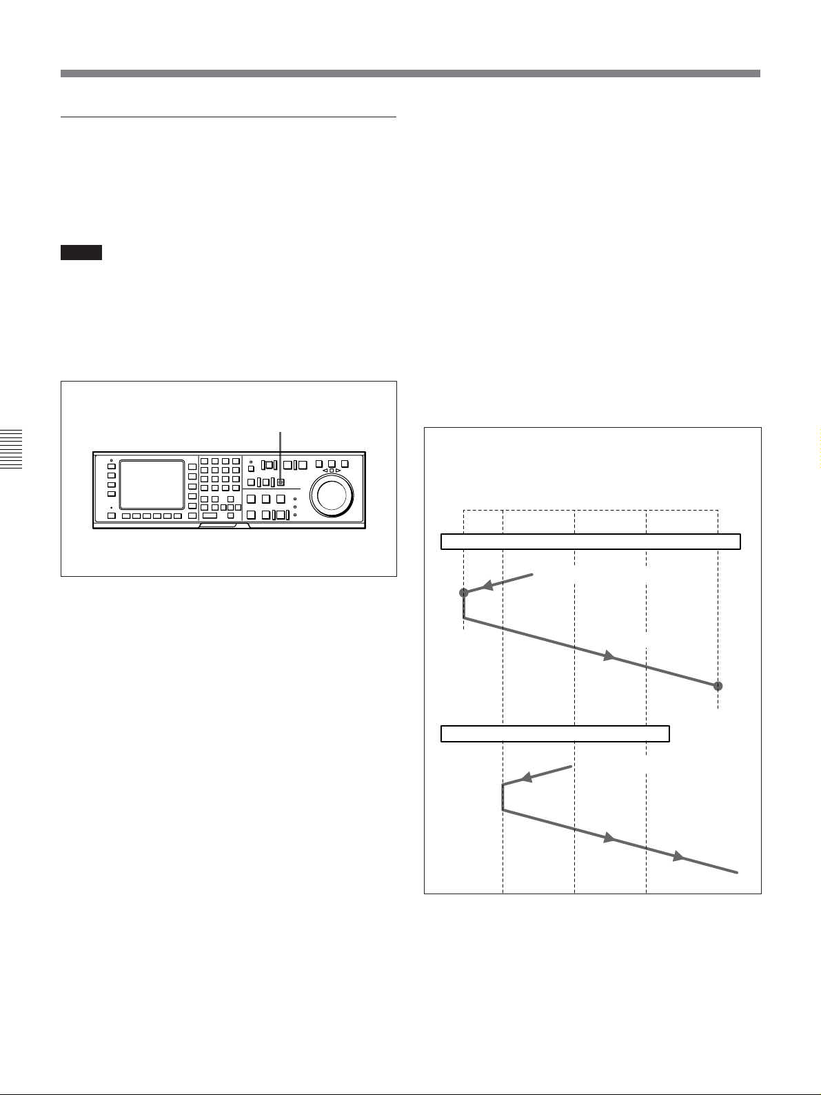
5-4 Playback
Performing DMC playback
There are two methods of starting DMC playback.
•Starting playback at the on-air cue from the on-air
start point
•Starting playback immediately after prerolling
Notes
•To avoid operation errors, we recommend that you
use the VTR alone when performing DMC playback.
•If two VTRs are connected for editing, you can still
perform DMC playback, but only on the recorder
VTR, and only when both the RECORDER and
PLAYER buttons are off.
Chapter 5 Recording/Playback
1,2
To start playback immediately after prerolling
Press the PREVIEW button.
The PREVIEW button lights up. When the tape passes
the speed variation start point, DMC playback starts
and continues at the speed(s) stored in memory. When
the tape passes the speed variation end point, normalspeed playback resumes.
To stop the tape during DMC playback
Press the STOP button.
To exit DMC playback mode
Press the ALT/[F7] (DMC) button while holding down
the CLR button in HOME menu.
During DMC playback, the tape runs as shown in the
diagram below.
On-air
Preroll
start
point
point
$$ $ $ $
Speed
variation
start point
Speed
variation
ending
point
On-air
end
point
Performing DMC playback
To start playback at the on-air cue from the
on-air start point
1 Press the REVIEW button.
The REVIEW button lights up and the tape is cued
up to the on-air start point. After the tape is cued
up, the REVIEW button flashes.
2 Press the REVIEW button again at the moment the
on-air cue is given.
The REVIEW button lights up. When the tape
passes the speed variation start point, DMC
playback starts and continues at the speed(s) stored
in memory. When the tape passes the speed
variation end point, normal-speed playback starts
and the tape stops at the on-air end point.
Starting DMC playback at the on-air cue from the on-air start point
Stop
Press the
REVIEW
button again
at the on-air
cue.
Starting DMC playback immediately after preroll
Press the REVIEW button.
Normalspeed
playback
DMC playback
Press the PREVIEW button.
Normalspeed
playback
DMC
playback
DMC playback
Normalspeed
playback
Stop
Normal-speed
playback
5-12 Chapter 5 Recording/Playback
Page 93

5-4-5 Program Playback
In program playback mode, you can play back a tape at
a previously determined speed. This speed may be set
within a range of normal playback speed ±15% (in
0.1% steps).
Installation of the optional BKDW-507 Audio
Program Play Board allows you to obtain higher
quality audio output during program playback.
Before performing program playback
Set 111. PROGRAM PLAY in the VTR SETUP menu
to enable.
Performing program playback
32
Chapter 5 Recording/Playback
1
1 Press the search dial or the JOG button to light up
the JOG button, press the ALT button, and then
rotate the search dial while holding down the [F8]
(P-PLAY) button to specify the playback speed.
The adjustment range is ±15% normal playback
speed.
2 Press the PLAY button while holding down the
[F8] (P-PLAY) button.
The [F8] (P-PLAY) button lights up, and program
playback starts.
You can change the playback speed during
program playback by rotating the search dial while
holding down the [F8] (P-PLAY) button.
3 Press the STOP button to stop program playback.
Program play mode is canceled.
Note that the playback speed during program play
does not change until you change the playback
speed or you turn the power off. Normal playback
speed resumes when you turn the power off, then
on again.
Chapter 5 Recording/Playback 5-13
Page 94

5-4 Playback
Chapter 5 Recording/Playback
5-14 Chapter 5 Recording/Playback
Page 95

6-1 Basic Automatic Editing
Chapter 6 Editing
6-1-1 Overview of Automatic Editing
Automatic edit modes
The VTR provides the following two modes for
automatic editing:
• Assemble mode
New scenes are added to the end of previously
recorded scenes.
CTL signals, time codes, video and audio signals on
tape in the player are recorded onto tape in the
recorder VTR.
•Insert mode
New scenes are inserted into the middle of previously
recorded scenes. CTL signals on tape in the recorder
VTR are not overwritten. Video, digital audio, cue
audio, and time code signals can be recorded
separately.
Both of these two edit modes support DMC editing.
In insert mode, you can also use split editing.
Interpolation of time codes by the CTL
counter
To use time codes as addresses of edit points, the time
codes must be recorded on the tape in ascending order.
As long as they are in ascending order, time codes do
not have to be continuous.
The CTL counter automatically interpolates data for
editing even if there are breaks in the continuity in the
time codes.
Time codes recorded during automatic editing
During automatic editing, time codes recorded on the
tape always follow immediately after time codes
recorded right before an edit start point, regardless of
the setting of the [F6] (TCG SOURCE) and [F7] (TCG
MODE) buttons of TC menu.
Steps in automatic editing
The sequence of steps that are taken to do automatic
editing with two VTRs is as follows:
Select the edit mode (page 6-3).
.
Set edit points for the recorder and player VTR
(page 6-3).
.
Preview the edit section (page 6-8).
.
Perform the edit (page 6-11).
.
Confirm and modify the edit points
(pages 6-7 and 6-9).
.
Confirm the results of the edit (page 6-13).
Editing precautions
Using an editing control unit
When using an editing control unit to control the VTR,
set the edit delay on the control unit so that CUT-IN
and CUT-OUT commands are sent to the VTR five
frames ahead of the actual edit point.
Video signals output to a monitor
While in E-E mode or when playing back in edit mode,
the V-sync phase of the video output is delayed 6H (on
the DVW-A500/1 and 500/1) or 4H (on the DVWA500P/1 and 500P/1) with respect to the external
reference signal. You can also adjust the V-sync phase
so that it is in sync with the external reference signal
phase, but without affecting the video signal delay.
Change the V-sync phase through 701. SELECTION
OF VIDEO/SYNC DELAY in the VTR SETUP menu.
Chapter 6 Editing
For details on the switch settings necessary for changing the
time codes recorded, refer to “4-3 TC Menu” on page 4-18
and the 600 menus in the VTR SETUP menu.
Chapter 6 Editing 6-1
Page 96

6-1 Basic Automatic Editing
6-1-2 Setting Switches and Menus
Before editing, set the following switches as shown
below.
AUDIO INPUT/MONITOR SELECT buttons or the [F1] (A-IN CH1)
to [F4] (A-IN CH4) buttons in the PF2 menu: input signal
Recorder VTR
POWER switch: ON
VIDEO INPUT SELECT button or the [F1] (VIDEO
IN) button in the PF1 menu: input signal
REC level controls: recording levels
Chapter 6 Editing
[F1] (TIMER SEL) button in the TC menu:
CTL or TC
POWER switch: ON
PB level controls:
playback levels
REMOTE buttons: None of
these buttons light up.
Player VTR
REMOTE buttons: 1(9P) button
lights up.
[F1] (TIMER SEL) button in the TC menu: CTL or TC
6-2 Chapter 6 Editing
Setting switches and menus
Page 97

6-1-3 Selecting the Edit Mode
6-1-4 Setting Edit Points
Select assemble or insert mode.
[F3] (ASSEMBLE) button in the HOME menu
[F4] (INS TC) to [F10] (INS CUE) buttons in the HOME menu
Selecting the edit mode
Press one of the following buttons to select the
respective edit mode:
• Assemble mode: [F3] (ASSEMBLE) button in the
HOME menu
• Insert mode: the appropriate INSERT button in
the HOME menu ([F4] (INS TC), [F5] (INS
VIDEO), [F6] (INS A-CH1), [F7] (INS A-CH2),
[F8] (INS A-CH3), [F9] (INS A-CH4), [F10] (INS
CUE))
This section describes how to set edit points (IN and
OUT points). In insert mode, a technque called split
editing allows you to set edit points separately for
video and audio.
Positioning and setting edit points
To position and set edit points, follow the procedure
below.
1
3
Positioning and setting edit points
2
1 Press the RECORDER or PLAYER button to
select the VTR for which edit points are to be set.
The button lights up.
Chapter 6 Editing
2 Rotate the search dial in jog or shuttle mode to
position the edit point.
For details on jog or shuttle playback, refer to “5-4-2
Variable Speed Playback in Jog/Shuttle/Variable
Modes” on page 5-8.
3 Press the IN (or OUT) button while holding down
the ENTRY button.
The time data for the IN (or OUT) point appears in
the menu display.
4 Repeat Steps 1 to 3 to set the remaining edit
points.
When IN points are set for both the recorder and
player VTRs, the PREVIEW and AUTO EDIT
buttons flash to show that the VTR is ready for
preview or edit.
Chapter 6 Editing 6-3
Page 98

6-1 Basic Automatic Editing
Setting edit points with the numeric buttons
1 Press the RECORDER or PLAYER button to
select the VTR for which edit points are to be set.
The button lights up.
2 Enter the edit point data with the numeric buttons.
For example, to enter 01H00M30S00F, press 1, 0,
0, 3, 0, 0, 0. (The leading 0 is not required. When
the entered value is less than eight digits, the
leading digit(s) are set to 0 when you press the
Chapter 6 Editing
SET button.)
2
CLR button
1
3
Setting edit points with the numeric buttons
3 Press the SET button to set the input data.
SET is
DOLBY
NR
CH.COND
PRE
REÅD
off
LOCK
TCR PLÅY 4FD F1
CONFI
01Ó04µ58ß00
off
ÅIN 00:00:00:00 ÅOUT 00:00:00:00
ÅSSEM-
IN 00:00:00:00 OUT 00:00:00:00
BLE
PLÅYER
off
INS
01Ó04µ58ß00
TC
ÅIN 00:00:00:00 ÅOUT 00:00:00:00
off
IN 00:00:00:00 OUT 00:00:00:00
INS
INS
VIDEO
Å-CH1
off
Å-CH2
off
DIGITÅL
GREEN
SET 01 00 30 00
INS
INS
Å-CH3
off
off
HOME
INS
Å-CH4
off
ƒ
ƒ
INS
CUE
off
displayed.
4 Press the IN (or OUT) button.
The time data for the IN (or OUT) point appears in
the menu display.
Note
If you set four or more points for the recorder and
player VTRs, a message will appear on the menu
display, indicating that editing is impossible. Delete
all unnecessary edit points by pressing the IN (OUT)
button while holding down the CLR button.
DOLBY
NR
CH.COND
PRE
REÅD
off
LOCK
TCR PLÅY 4FD F1
CONFI
01Ó04µ58ß00
off
ÅIN 00:00:00:00 ÅOUT 00:00:00:00
ÅSSEM-
IN 00:00:00:00 OUT 00:00:00:00
BLE
PLÅYER
off
INS
01Ó04µ58ß00
TC
ÅIN 00:00:00:00 ÅOUT 00:00:00:00
off
IN 00:00:00:00 OUT 00:00:00:00
INS
INS
VIDEO
Å-CH1
off
Å-CH2
off
GREEN
INS
off
DIGITÅL HOME
INS
Å-CH3
off
To delete entered data
Press the CLR button.
INS
Å-CH4
off
INS
CUE
off
ƒ
ƒ
Entered data are
displayed.
For details, refer to “Deleting edit points” on page 6-9.
About automatic edit point setting
Editing requires a total of four edit points: IN and
OUT points for both the recorder and player VTRs.
However, as soon as you set three edit points, the VTR
automatically sets the fourth point.
In the figure below, the points enclosed in a box have
been set manually, while the OUT point for the player
VTR has been set automatically.
IN point OUT point
Recorder VTR
Player VTR
$$
44
IN point OUT point
6-4 Chapter 6 Editing
Automatic edit point setting
Whether set manually or automatically, all edit points
can be changed or deleted at any time.
Page 99
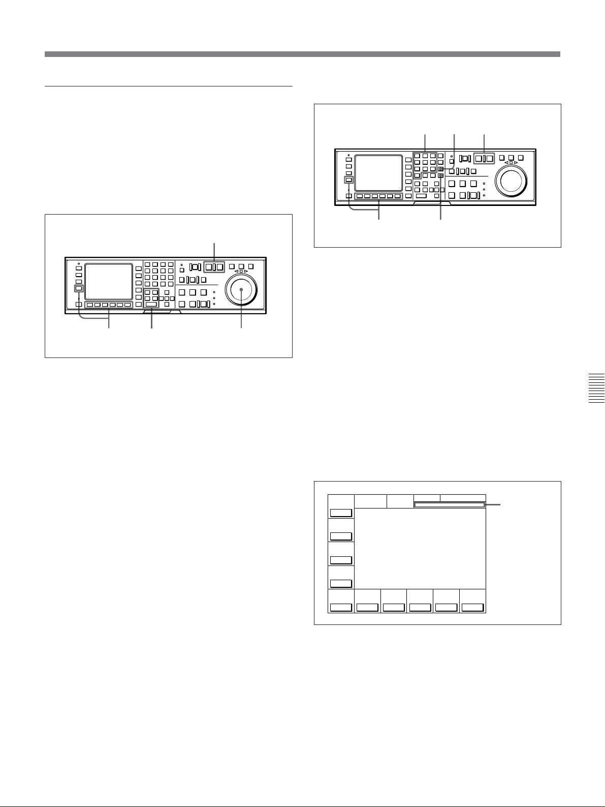
Split editing
Setting edit points with the numeric buttons
Positioning and setting edit points
Split editing allows you to set edit points separatelty
for video and audio. Set audio edit points with the
AUDIO IN/OUT buttons and video edit points with
the IN/OUT buttons.
Split editing, however, can only be done when the
recorder VTR is in insert mode.
2
413
Positioning and setting edit points
1 Press the appropriate INSERT button in HOME
menu ([F4] (INS TC), [F5] (INS VIDEO),
[F6] (INS A-CH1), [F7] (INS A-CH2), [F8] (INS
A-CH3), [F9] (INS A-CH4), [F10] (INS CUE)).
2 Press the RECORDER or PLAYER button to
select the VTR for which edit points are to be set.
The button lights up.
3 To locate the edit points, rotate the search dial in
jog or shuttle mode.
For details on jog/shuttle/variable playback modes,
refer to “5-4-2 Variable Speed Playback in Jog/Shuttle/
Variable Modes” on page 5-8.
4 Press the IN (OUT, AUDIO IN or AUDIO OUT)
button while holding down the ENTRY button.
3
CLR button
1
Setting edit points with the numeric buttons
4
2
1 Press the appropriate INSERT button in HOME
menu ([F4] (INS TC), [F5] (INS VIDEO),
[F6] (INS A-CH1), [F7] (INS A-CH2), [F8] (INS A-
CH3), [F9] (INS A-CH4), [F10] (INS CUE)).
2 Press the RECORDER or PLAYER button to select
the VTR for which edit points are to be set.
The button lights up.
3 Enter the edit point data with the numeric buttons.
For example, to enter 01H00M30S00F, press 1, 0,
0, 3, 0, 0, 0. (The leading 0 is not required. When
the entered value is less than eight digits, the
leading digit(s) are set to 0 when you press the SET
button.)
DOLBY
NR
CH.COND
PRE
REÅD
off
LOCK
TCR PLÅY 4FD F1
CONFI
01Ó04µ58ß00
off
ÅIN 00:00:00:00 ÅOUT 00:00:00:00
ÅSSEM-
IN 00:00:00:00 OUT 00:00:00:00
BLE
PLÅYER
off
INS
01Ó04µ58ß00
TC
ÅIN 00:00:00:00 ÅOUT 00:00:00:00
off
IN 00:00:00:00 OUT 00:00:00:00
INS
INS
VIDEO
Å-CH1
off
Å-CH2
off
GREEN
INS
off
DIGITÅL HOME
INS
Å-CH3
Å-CH4
off
INS
off
INS
CUE
off
Input data
are displayed.
ƒ
ƒ
Chapter 6 Editing
5 Repeat Steps 2 to 4 to set the remaining edit
points.
To delete entered data
Press the CLR button.
(Continued)
Chapter 6 Editing 6-5
Page 100

6-1 Basic Automatic Editing
4 Press the SET button to set the input data.
NR
DOLBY
PRE
REÅD
off
LOCK
TCR PLÅY 4FD F1
CONFI
off
ÅIN 00:00:00:00 ÅOUT 00:00:00:00
ÅSSEM-
IN 00:00:00:00 OUT 00:00:00:00
BLE
PLÅYER
off
INS
TC
ÅIN 00:00:00:00 ÅOUT 00:00:00:00
off
IN 00:00:00:00 OUT 00:00:00:00
INS
VIDEO
Å-CH1
off
CH.COND
DIGITÅL
GREEN
HOME
SET 01 00 30 00
01Ó 04µ 58ß 00ƒ
01Ó 04µ 58ß 00ƒ
INS
INS
INS
INS
off
Å-CH2
off
Å-CH3
off
Å-CH4
off
INS
CUE
off
SET is
displayed.
Recorder VTR
Player VTR
AUDIO
IN point
AUDIO
IN point
Automatic split edit point setting
IN point
$$
44
$$
44
IN point
AUDIO
OUT point
AUDIO
OUT point
OUT point
OUT point
5 Press the IN (OUT, AUDIO IN or AUDIO OUT)
button.
The time data for the IN (OUT, AUDIO IN or
AUDIO OUT) point appears in the menu display.
Note
During split editing, if you set six or more points for
the recorder and player VTRs, the time data for the
edit points flash, indicating that editing is impossible.
Chapter 6 Editing
Delete all unnecessary edit points by pressing the IN,
OUT, AUDIO IN, or AUDIO OUT button while
holding down the CLR button.
For details, refer to “Deleting edit points” on page 6-9.
About automatic split edit point setting
Split editing requires a total of eight edit points: four
edit points for video editing (IN and OUT points for
both the recorder and player VTRs) and four edit
points for audio editing (AUDIO IN and OUT points
for both the recorder and player VTRs). However, as
soon as you set five edit points, the VTR automatically
sets the remaining three points. For example, if you
set three edit points for video (or audio) and two for
audio (or video), the remaining three points are
automatically set, regardless of whether these points
are for the recorder or player.
In the following example, the points enclosed in a box
have been set manually and the AUDIO OUT point for
the recorder VTR, and the AUDIO IN and OUT points
for the player VTR have been set automatically.
Note that whether set manually or automatically, all
edit points can be changed or deleted at any time.
You can select audio cut-in, crossfade, and fade in/out
in edits, as well as their duration, by VTR SETUP
menu.
For details, refer to the menu items in the 300 range in the
VTR SETUP menu.
When the AUDIO IN point is not set for insert
editing of audio only
As long as the AUDIO OUT point is set, the VTR is
ready for preview or editing. If the AUDIO IN point
has not been set, the current tape address is
automatically set as the AUDIO IN point.
Using a VTR without the split editing function
If the player VTR does not support the separate setting
of edit points for video and audio, you can set AUDIO
IN and AUDIO OUT points on the recorder and three
video edit points to enable split editing.
6-6 Chapter 6 Editing
 Loading...