

Page 1

ROUTING SWITCHER
DVS-128
BACKUP CPU BOARD
BKDS-12890
BACKUP POWER SUPPLY UNIT
BKDS-12891
ANALOG AUDIO INPUT BOARD
BKDS-AA10
ANALOG AUDIO OUTPUT BOARD
BKDS-AA11
ANALOG VIEDO INPUT BOARD
BKDS-AV10
ANALOG VIDEO OUTPUT BOARD
BKDS-AV11
AES/EBU INPUT BOARD
BKDS-DA10
AES/EBU OUTPUT BOARD
BKDS-DA11
MAINTENANCE MANUAL Part 1
1st Edition
Page 2

! WARNING
This manual is intended for qualified service personnel only.
To reduce the risk of electric shock, fire or injury, do not perform any servicing other than that
contained in the operating instructions unless you are qualified to do so. Refer all servicing to
qualified service personnel.
! WARNUNG
Die Anleitung ist nur für qualifiziertes Fachpersonal bestimmt.
Alle Wartungsarbeiten dürfen nur von qualifiziertem Fachpersonal ausgeführt werden. Um die
Gefahr eines elektrischen Schlages, Feuergefahr und Verletzungen zu vermeiden, sind bei
Wartungsarbeiten strikt die Angaben in der Anleitung zu befolgen. Andere als die angegeben
Wartungsarbeiten dürfen nur von Personen ausgeführt werden, die eine spezielle Befähigung
dazu besitzen.
! AVERTISSEMENT
Ce manual est destiné uniquement aux personnes compétentes en charge de l’entretien. Afin
de réduire les risques de décharge électrique, d’incendie ou de blessure n’effectuer que les
réparations indiquées dans le mode d’emploi à moins d’être qualifié pour en effectuer d’autres.
Pour toute réparation faire appel à une personne compétente uniquement.
DVS-128 Serial No. 10001 and Higher
BKDS-12890 Serial No. 10001 and Higher
BKDS-12891 Serial No. 10001 and Higher
BKDS-AA10 Serial No. 10001 and Higher
BKDS-AA11 Serial No. 10001 and Higher
BKDS-AV10 Serial No. 10001 and Higher
BKDS-AV11 Serial No. 10001 and Higher
BKDS-DA10 Serial No. 10001 and Higher
BKDS-DA11 Serial No. 10001 and Higher
DVS-128E MMP1
Page 3

CAUTION
Danger of explosion if battery is incorrectly
replaced.
Replace only with the same or equivalent type
recommended by the manufacturer.
Dispose of used batteries according to the
manufacturer’s instructions.
Vorsicht!
Explosionsgefahr bei unsachgemäßem
Austausch der Batterie.
Ersatz nur durch denselben oder einen vom
Hersteller empfohlenen ähnlichen Typ.
Entsorgung gebrauchter Batterien nach Angaben
des Herstellers.
ATTENTION
Attention-when the product is installed in Rack:
1. Prevention against overloading of branch circuit
When this product is installed in a rack and is
supplied power from an outlet on the rack, please
make sure that the rack does not overload the supply
circuit.
2. Providing protective earth
When this product is installed in a rack and is
supplied power from an outlet on the rack, please
confirm that the outlet is provided with a suitable
protective earth connection.
3. Internal air ambient temperature of the rack
When this product is installed in a rack, please make
sure that the internal air ambient temperature of the
rack is within the specified limit of this product.
4. Prevention against achieving hazardous
condition due to uneven mechanical loading
When this product is installed in a rack, please make
sure that the rack does not achieve hazardous
condition due to uneven mechanical loading.
Il y a danger d’explosion s’il y a remplacement
incorrect de la batterie.
Remplacer uniquement avec une batterie du
même type ou d’un type équivalent recommandé
par le constructeur.
Mettre au rebut les batteries usagées
conformément aux instructions du fabricant.
ADVARSEL!
Lithiumbatteri-Eksplosionsfare ved fejlagtig
håndtering.
Udskiftning må kun ske med batteri
af samme fabrikat og type.
Levér det brugte batteri tilbage til leverandøren.
DVS-128E MMP1
1 (P)
Page 4

Page 5

Table of Contents
Manual Structure
Purpose of this manual .............................................................................................. 3
Related manuals......................................................................................................... 3
Contents ..................................................................................................................... 4
Trademarks ................................................................................................................ 4
1. Installation
1-1. Operating Environment ...............................................................................1-1
1-2. Power Supply ..............................................................................................1-1
1-2-1. Power Specifications ..................................................................1-1
1-2-2. Power Cord.................................................................................1-1
1-3. Connectors...................................................................................................1-2
1-4. Input and Output Signals of Connectors .....................................................1-3
1-5. Cross Point Switching Timing ....................................................................1-4
1-5-1. Selection of the Cross Point Switching Timings........................1-4
1-5-2. Audio Clock Signal ....................................................................1-4
1-6. Backup System............................................................................................ 1-5
1-6-1. Redundant Power Supply System ..............................................1-5
1-6-2. Redundant CPU Board ...............................................................1-5
1-7. System Connection......................................................................................1-6
1-7-1. S-BUS Data Link .......................................................................1-6
1-8. External Dimensions ...................................................................................1-9
1-9. Rack Mounting.......................................................................................... 1-10
1-10. Installation of Options............................................................................... 1-14
1-10-1. Installation of Plug-in Boards ..................................................1-14
1-10-2. Analog Audio Input and Output Boards ..................................1-16
1-10-3. Inserting/Pulling Out of Plug-in Boards .................................. 1-23
1-10-4. Installation of Backup Power Supply Unit (BKDS-12891) .....1-27
1-11. Setting the On-Board Switches and Explanation of LEDs .......................1-28
1-11-1. CPU-275 board (DVS-128/BKDS-12890) .............................. 1-28
1-11-2. AAP-1 board (BKDS-AA10) ...................................................1-31
1-11-3. AAP-2 board (BKDS-AA11) ...................................................1-32
1-11-4. LE-206 board (BKDS-AA11) ..................................................1-32
1-11-5. ASW-55 board (BKDS-AA11) ................................................1-33
1-11-6. DAP-19 board (BKDS-DA10) .................................................1-34
1-11-7. DAP-22 board (BKDS-DA11) .................................................1-35
1-11-8. AVP-1 board (BKDS-AV10) ...................................................1-36
1-11-9. AVP-2 board (BKDS-AV11) ...................................................1-37
1-12. Introduction of ISR ...................................................................................1-38
1-12-1. Equipment Connection .............................................................1-38
1-12-2. REMOTE3 Mode Selection .....................................................1-40
DVS-128E MMP1
1
Page 6

2. Service Overview
2-1. Removal/Installation of Front Panel ...........................................................2-1
2-2. Location of Main Parts................................................................................ 2-2
2-3. Replacement of Lithium Battery (CR2025) ................................................2-3
2-4. Data Backup ................................................................................................2-4
2-4-1. Installing BZR-20.......................................................................2-4
2-4-2. Data Backup (Uploading) .......................................................... 2-5
2-4-3. Data Downloading ..................................................................... 2-7
2-5. Spare Parts...................................................................................................2-8
2-6. Notes on Repair Parts.................................................................................. 2-9
3. Replacement of Main Parts
3-1. Replacement of Power Unit ........................................................................ 3-1
3-2. Replacement of Fans ...................................................................................3-2
4. Periodical Maintenance and Inspection
4-1. Periodical Maintenance ...............................................................................4-1
4-2. Cleaning ......................................................................................................4-2
4-2-1. Filters..........................................................................................4-2
4-2-2. Fans ............................................................................................4-2
5. Overall Block Diagram
2
DVS-128E MMP1
Page 7

Purpose of this manual
Related manuals
Manual Structure
This manual is the maintenance manual part1 of routing switcher DVS-128 series.
This manual is intended for use by trained system and service engineers, and
provides the information that is required to install and maintenance information.
Besides this “maintenance manual part 1”, the following manuals are available for
DVS-128 series.
The parts number of each manual is one as of APRIL 1999.
..
. Operation Manual (Supplied with the DVS-128.)
..
This manual describes the outline, system connection example and specifications.
Part No.: 3-867-319-01
..
. Installation Manual (Software) (Supplied with the DVS-128.)
..
This manual describes the software initialization or operation confirmation.
This manual also describes the information on the main component equipment of a
routing switcher system as well as this unit.
Part No.: 3-194-350-02
..
. Maintenance Manual Part 2 (Not supplied with the DVS-128.)
..
This manual describes the information that premises the parts level
service(adjustments, schematic diagrams, board layouts, detailed parts list, etc.). If
this manual is required, please contact your local Sony Sales Office/Service Center.
Part No: 9-968-539-01
..
. Protocol Manual (Not supplied with the DVS-128.)
..
This manual describes the protocol for controlling this unit.
The manuals below are providZed for the protocol that this unit can support.
If this manual is required, please contact your local Sony Sales Office/Service Center.
S-BUS PROTOCOL AND COMMAND SPECIFICATIONS
(S-BUS remote terminal control protocol)
Part No.: 9-977-477-12
ROUTING SWITCHER SYSTEM PROTOCOL AND COMMAND SPECIFICATIONS
(Sony cart protocol)
Part No.: 9-967-261-21
BVS/DVS Series PROTOCOL AND COMMAND SPECIFICATIONS
(Sony production switcher protocol)
Part No.: 9-967-262-21
DVS-128E MMP1
DVS-V3232B/6464B Series TECHNICAL MANUAL
(Sony audio mixer protocol)
Part No.: 9-967-547-11
3
Page 8

Contents
Trademarks
This manual is organized by following sections.
Section 1 Installation
Explains the information that is required to install (environment, external dimensions, initial setting, etc.).
Section 2 Service Overview
Expins fundamental area of the information that is required to service, (removal of
cabinet and locations of main part), replace of flash memory and plug-in board list.
Section 3 Replacement of Main Parts
Explains replacement of the power supply unit and fans.
Section 4 Periodic Maintenance and Inspection
Explains the recommended periodic maintenance and cleaning procedure.
Section 5 Overall Block Diagram
Describes the overall block diagram.
Trademarks and registered trademarks used in this manual are follows.
. MS-DOS is a registered trademark of Microsoft Corporation.
. Windows is a registered trademark of Microsoft Corporation.
. IBM and AT are registered trademarks of International Business Machine, Inc.
4
DVS-128E MMP1
Page 9
Section 1
Installation
1-1. Operating Environment
w
Do not put this unit in a place subject to excessive oil
painting, steam, moisture, or dust. This may cause a fire or
electric shock.
m
. Install the unit in a well ventilated place to prevent a
temperature rise in the unit. Never cover the ventilation
holes of the outer frame.
. Never install the unit near a heat source.
Operating temperature 5 dC to 40 dC
Strorage temperature _20 dC to + 60 dC
Operating humidity 10 % to 90 %
1-2. Power Supply
1-2-1. Power Specifications
Power requirements AC100 to 240 V ±10 %
Power frequency 50/60 Hz
Current drain 100 V AC : 9.4 A (max.)
240 V AC : 3.8 A (max.)
Inrush current Power voltage 100 V IN :40 A
(max.)
Power voltage 240 V IN : 80 A
(max.)
Power supply capacity +6 V DC : 45 A (max.)
_6 V DC : 45 A (max.)
Power consumption 600 VA (max.)
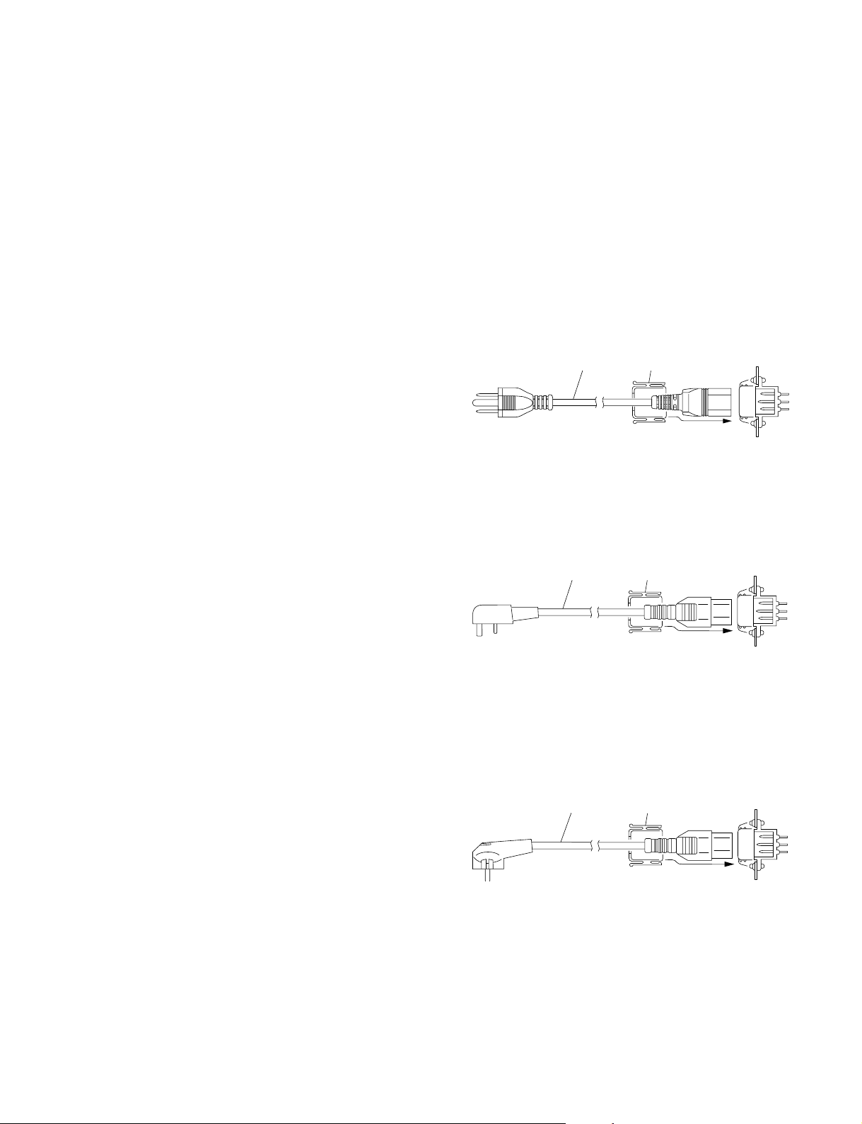
1-2-2. Power Cord
w
The power cords are not supplied with DVS-128. Be sure
to use the power cords that are applicable to the places in
the world.
For the customer in the U.S.A. and Canada
Required Parts
1 Power Cord, 125 V 10 A (2.4 m) : 1-557-377-11
2 Plug Holder B (Black) : 2-990-242-01
1
For the customer in the United Kingdom
Required Parts
DK-2401 (EK)
1 Power Cord, 250 V 10 A (2.4 m)
2 Plug Holder B (Black) : 2-990-242-01
1
For the customer in the all European countries
except the United Kingdom
Required Parts
DK-2401 (AE)
1 Power Cord, 250 V 10 A (2.4 m)
2 Plug Holder B (Black) : 2-990-242-01
2
2
AC inlet
AC inlet
n
The capacity of the AC power must be commensurate with
an inrush current. If the capacity of the AC power is not
adequately large, the breaker of the AC power on the
supply side will operate or the unit will not operate
normally.
DVS-128E MMP1
1
2
AC inlet
n
For the customer outside of the area as shown above,
please contact your local Sony Sales Office/Service
Center.
1-1
Page 10

1-3. Connectors
1-3. Connectors
When connecting cables to each connector on the rear panel at the time of installing, connecting or
servicing, connect the following connectors or their equivalents.
Connector function name on rear panel Connector Sony part No.
(DVS-128)
REMOTE 1 A, B, C BNC, 75 Z_
REMOTE 4
A, B REF. IN
A, B WORD SYNC. IN
(BKDS-AV10)
ANALOG VIDEO INPUT 1 to 32
(BKDS-AV11)
ANALOG VIDEO OUTPUT 1 to 32
ANALOG VIDEO MONITOR OUTPUT
(BKDS-DA10)
DIGITAL AUDIO INPUT 1 to 32
(BKDS-DA11)
DIGITAL AUDIO OUTPUT 1 to 32
DIGITAL AUDIO MONITOR OUTPUT
(DVS-128) D-sub 9-pin, Male
REMOTE 2 A, B Connector 9-pin, Male 1-560-651-00
(BKDS-AA11) Junction Shell 9-pin 1-561-749-00
ANALOG AUDIO MONITOR OUTPUT
(DVS-128) D-sub 9-pin, Female
REMOTE 3 Connector 9-pin, Female 1-563-815-21
(BKDS-AA10) D-sub 25-pin, Male
ANALOG AUDIO INPUT 1 to 8 Connector 25-pin, Male 1-560-904-11
(BKDS-AA11) Junction Shell 25-pin 1-563-377-11
ANALOG AUDIO OUTPUT 1 to 8
(*1) : The analog video outputs of both the channels 1 to 8 and the channels 17 to 24 have the two output channels respectively.
(*2) : The digital audio outputs of both the channels 1 to 8 and the channels 17 to 24 have the two output channels respectively.
(*1)
(*2)
Junction Shell 9-pin 1-561-749-00
1-2
DVS-128E MMP1
Page 11
_ EXT VIEW _
1
5
69
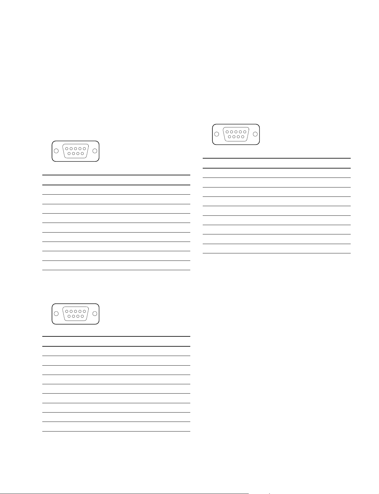
1-4. Input and Output Signals of Connectors
1-4. Input and Output Signals of
Connectors
Input and output signals of the connectors on the rear panel
are shown as follows. Refer to the illustration for the pin
assignment.
1. DVS-128 (CN-1704 board)
REMOTE 2 : RS-422A (D-sub 9-pin Female)
5
_ EXT VIEW _
Pin No. Signal Name
1 FG : Frame ground
2 TX (_) : Transmitted data (_)
3 RX (+) : Received data (+)
4 GND : Common ground
5 _ : Non connect
6 GND : Common ground
7 TX (+) : Transmitted data (+)
8 RX (_) : Received data (_)
9 _ : Non connect
1
69
2. BKDS-AA10 (CNI-3/4 boards)
ANALOG AUDIO INPUT 1 to 8 : 25-pin Female
*1
3. BKDS-AA11 (CNO-3 board)
MONITOR OUT : D-sub 9-pin Female
Pin No. Signal Name
1 MONITOR-L (HOT)
2 MONITOR-L (COLD)
3 FRAME-GND
4 MONITOR-R (HOT)
5 MONITOR-R (COLD)
6 MONITOR-L (GND)
7 _
8 _
9 MONITOR-R (GND)
ANALOG AUDIO OUTPUT 1 to 8 : 25-pin Female
*1
REMOTE 3 : RS-232C (D-sub 9-pin Male)
1
_ EXT VIEW _
Pin No. Signal Name
1 _ : Non connect
2 RX : Received data
3 TX : Transmitted data
4 DTR : Data terminal ready
5 GND : Signal ground
6 DSR : Data set ready
7 RTS : Request to send
8 CTS : Clear to send
9 _ : Non connect
DVS-128E MMP1
5
96
*1 : Refer to Section 1-10-2 for ANALOG AUDIO INPUT/OUTPUT 1 to 8 of
the BKDS-AA10/AA11.
1-3
Page 12

1-5. Cross Point Switching Timing
1-5-1. Selection of the Cross Point Switching Timings
1-5-2. Audio Clock Signal
1-5. Cross Point Switching Timing
1-5-1. Selection of the Cross Point Switching Timings
Cross points of all the audio and video signals are switched at the timing that is synchronized with the
reference input signal. The reference input signal can be selected for each matrix and OUTPUT board.
Using this function, the cross points can be switched at the different timings that are synchronized to the
difference reference input signals in units of circuit board. The desired input reference signal can be
selected by the slide switch on the respective matrix and OUTPUT board. Either position A or B can be
selected.
Relation between the selector switches and the matrix is described as follows.
Model name Board name Switch selection Selection of Remarks
BKDS-AV11 AVP-2 A REF A Switching synchronized with
B REF B Switching synchronized with
BKDS-AA11 AAP-2 A REF A Switching synchronized with
B REF B Switching synchronized with
BKDS-DA11 DAP-22 A REF A Switching synchronized with
B REF B Switching synchronized with
reference signal
REF A.
REF B.
REF A.
REF B.
REF A.
REF B.
n
The REF A signal must be input to the DVS-128 in order to enable the cross point switching locked to the
reference signal.
1-5-2. Audio Clock Signal
The clock signal that is extracted from either input word sync A or input word sync B, is used for audio
signal processing in the DVS-128. When any word sync signals are not input, the DVS-128 operates on
the clock signal that is synchronous with the input reference signal of the video signal.
n
Either REF A or REF B can be selected in each circuit board as the reference signal. It should be noted
that the same reference signal must be selected for both input and output of any audio signal processing
board. (both analog and digital audio processing boards.)
1-4
DVS-128E MMP1
Page 13
1-6-1. Redundant Power Supply System
(
)(
)
1-6-2. Redundant CPU Board
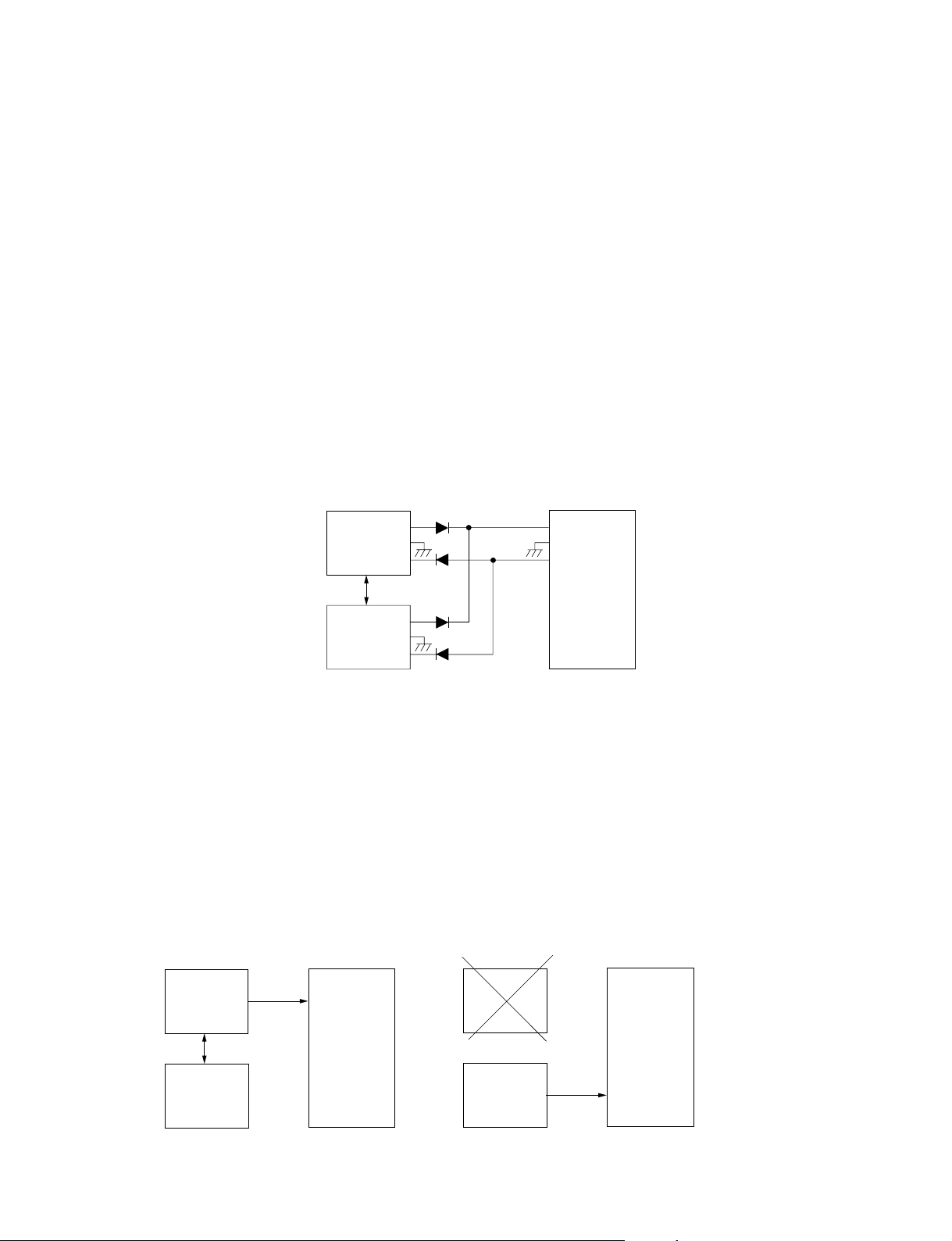
1-6. Backup System
1-6-1. Redundant Power Supply System
The DVS-128 is equipped with the backup power supply unit (BKDS-12891) in addition to the standard
power supply unit. Therefore the power supply system is duplexed, the DVS-128 can realize the high
reliability.
Either of the standard power supply unit and the backup power supply unit can support the full load of the
DVS-128 respectively that assures the stable operation even when either one of the power supply lines
fails, or when either one of the power supply units becomes defective.
DC outputs of the redundant power supply system are connected in the logic-OR connection using diodes
which supplies +5.6 V/_ 5.6 V to the power bus line of the mother board of the DVS-128. The +5.6 V/
_ 5.6 V powers are used in the respective boards where the required power supply voltages are generated
by either series regulator or DC-to-DC converter.
In addition, the redundant power supply system has the unique function (current balancing function) of
sharing the loads after balancing them. This function assures the highly reliable power supply operation
with sufficient margin when compared with the operation on a single power supply unit.
1-6. Backup System
+5.6 V
Power supply
Load balance control
Power supply
(Redundant
power supply
unit A
unit B
unit)
_5.6 V
Mother board
1-6-2. Redundant CPU Board
The DVS-128 can be equipped with the optional backup CPU board (BKDS-12890) in addition to the
CPU board (CPU-275) (called CPU-A hereafter) that is installed in the slot: CPU-A of the DVS-128. The
CPU board can be duplexed by installing the backup CPU board (called CPU-B hereafter) into the slot:
CPU-B of the DVS-128. The CPU-A performs control over the entire system of the DVS-128 in normal
condition.
If the CPU-A fails, the CPU-B backs up the full function of the CPU-A.
If either the CPU-A or CPU-B fails, the power status LED on the front panel turns on in red and an alarm
is triggered in the control terminal. It facilitates preventive maintenance.
DVS-128E MMP1
CPU-A
(Active)
CPU-B
(Stand-by)
Control
During normal operation
Mother board
CPU-A
Error
CPU-B
(Active)
When CPU-A has an error
Control
Mother board
1-5
Page 14

1-7. System Connection
1-7-1. S-BUS Data Link
1-7. System Connection
1-7-1. S-BUS Data Link
The digital routing switcher system is constituted with the S-BUS data link connected using a 75 Z coaxial cable.
The main equipment that constitutes the S-BUS data link is shown in the table below.
Type in S-BUS Model (Function name) Quantity Function/Role
data link
Primary Routing switcher 1 Controls the entire S-BUS data link.
station (P)
Secondary Switcher : 253 (max.) Controls the individual secondary
station (S)
Terminal PC terminal emulator 1 Establishes the various setups of the
* : (P) and (S) indicate the setting of the P/S switch on the CPU board inside the routing switcher.
*
*
DVS-128 (Routing switcher) It can work as a secondary station
DVS-V1616 (Video routing switcher) station.
DVS-V3232M (Video routing switcher) Communicates in accordance with the
DVS-V6464M (Video routing switcher) commands from the primary station.
DVS-A3232 (Audio routing switcher)
DVS-RS1616 (RS-422A remote routing switcher)
DVS-TC3232 (Time code routing switcher)
Remote control unit :
BKS-R3210 (X-Y control unit)
BKS-R3209 (32 button control unit)
BKS-R1607 (Universal control unit)
BKS-R1608 (16 button control unit)
BKS-R3206 (8 destination control unit)
BKS-R3280 (Single status display unit)
BKS-R3281 (Single status display unit)
too.
system.
The errors that have occurred in the
S-BUS line are displayed and
managed by the emulator.
n
Switchers other than DVS-128 can be also set as a primary station.
In this case, some functions are limited.
1-6
DVS-128E MMP1
Page 15
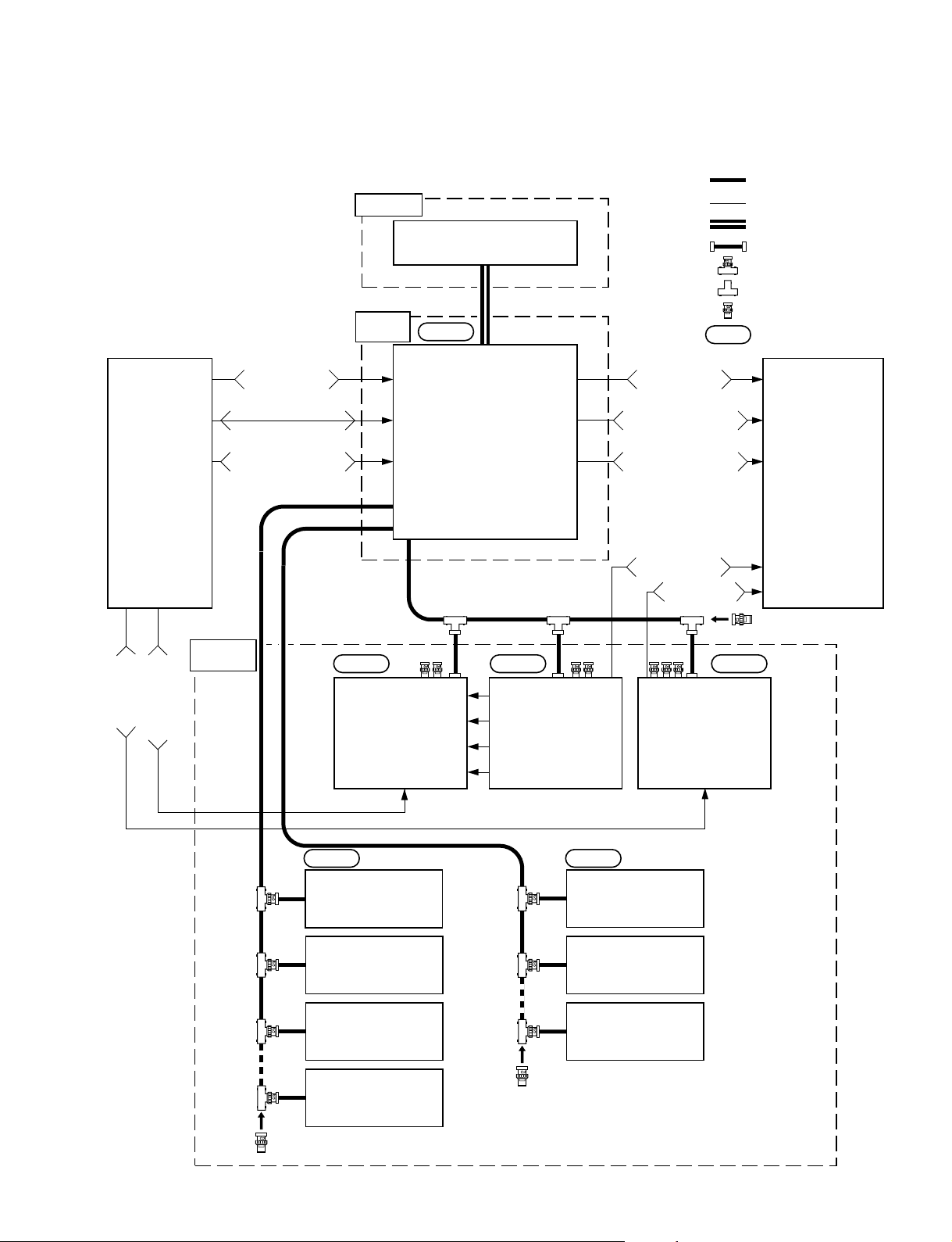
A connection example of the S-BUS data link with the DVS-128 set in a primary station is shown below.
Terminal
Personal computer
Terminal emulator software
Primary
startion
Level 1
REMOTE 3
1-7. System Connection
1-7-1. S-BUS Data Link
: S-BUS
: Signal line
: RS-232C
: 5C-2V coaxial cable
: T bridge (A)
: T bridge (B)
: 75 Z terminator
: Matrix level
Source
VTR
Time code
Digital video
Secondary
station
Analog video
Analog audio
channel 1/2
Analog audio
channel 3/4
REMOTE 1
REMOTE 1
C
B
REMOTE 1
Level 2
Video
routing switcher
DVS-V6464M
(S)
Routing switcher
DVS-128
A
Analog video
Analog audio
channel 1/2
(P)
Level 3 Level 4
Video
routing switcher
DVS-V6464M
(S)
Analog audio
channel 3/4
Digital video
Tyme code
Time code
routing switcher
DVS-TC3232
(S)
Destination VTR
DVS-128E MMP1
Level 1 Level 1
Remote control unit
BKS-R1607
Remote control unit
BKS-R1608
Remote control unit
BKS-R3209
Remote control unit
Remote control unit
BKS-R3206
Remote control unit
BKS-R3280
Remote control unit
BKS-R3281
BKS-R3210
1-7
Page 16
1-7. System Connection
1-7-1. S-BUS Data Link
Note on connection
. For the routing switcher that is used as a primary station, set the P/S switch on the CPU-275 board to
“P”.
. The number of secondary stations that a primary station can control is 253 (maximum).
. The number of secondary stations that can be connected to one S-BUS line is 128 (maximum).
. The cable length of one S-BUS line is 500 m (maximum) (when a 5C-2V cable is used).
. The T-type bridge installed in the last machine of an S-BUS line and the unused REMOTE1 connector
of each switcher are necessarily terminated using a 75 Z terminator.
. Only one REMOTE 1 connector of a routing switcher in a secondary station can be used.
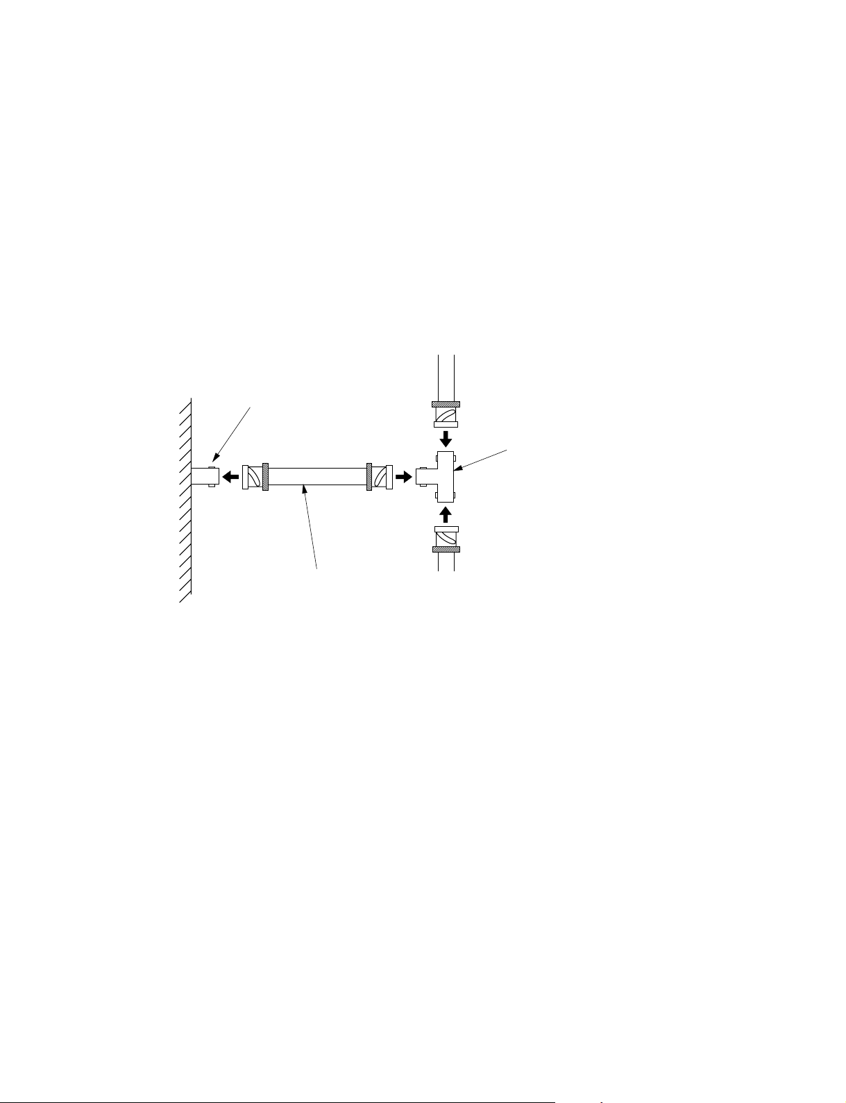
How to use T-type bridge
DVS-128 has a B-type T bridge. During connection, use a coaxial cable of less than 50 cm as shown
below.
REMOTE 1
(BNC Connector, Male)
T Bridge (B)
DVS-128
(Rear panel)
5C-2V coaxial cable
(50 cm or less)
1-8
DVS-128E MMP1
Page 17
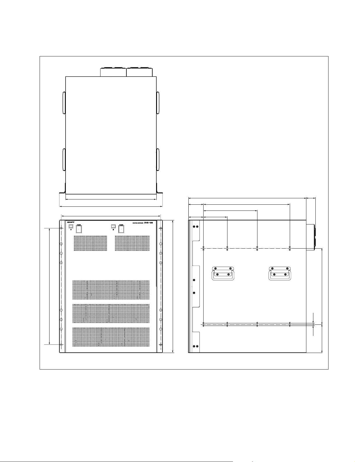
1-8. External Dimensions
Mass : 33 kg
1-8. External Dimensions
545
424
482
465
320 (14U)
70
111.1
250.8
550
403.2
43
355.5
13
132.2
DVS-128E MMP1
Unit : mm
1-9
Page 18

1-9. Rack Mounting
1-9. Rack Mounting
DVS-128 can be mounted in a 19-inch standard rack. Be sure to mount this unit in a rack accurately as
following procedure and notes.
Be sure to use the optional rack mount rail RMM-18DV.
Required Parts
. Rack mount rail RMM-18DV : 2 sets
<Components>
Rail assembly 2 pcs
Bracket 4 pcs
Plate nut (long) 4 pcs
Plate nut (small) 4 pcs
Screw B 4x8 16 pcs
Hexagon socket head cap screw C 4x12 8 pcs
Washer W4 8 pcs
. Screw B 4x8 for attaching the plate nut (long) : 16 pcs
. Screw RK 5x16 for rack-mount : 4 pcs
. Washer for rack-mount : 4 pcs
(Sony part No. : 2-297-913-01)
w
Fix the rack to the floor with bolts to prevent turning over the rack.
c
. Be sure to use the specified rail when rack mounting.
. Be sure to mount in the rack with three-person or more.
. Mount in a rack with a steady posture.
m
. If DVS-128 is mounted in the 19-inch standard rack, it is recommended to install a ventilation fan to
prevent a temperature rise in the rack. Make sure that all the units in the rack should be operated within
the temperature range of 10 dC to 35 dC.
. An installation manual is supplied with the rack mount rail RMM-18DV. However follow the proce-
dures explained on the following page in this maintenance manual. Because the rack mounting procedures of DVS-128 differ somewhat from the procedures explained in RMM-18DV installation manual.
1-10
DVS-128E MMP1
Page 19
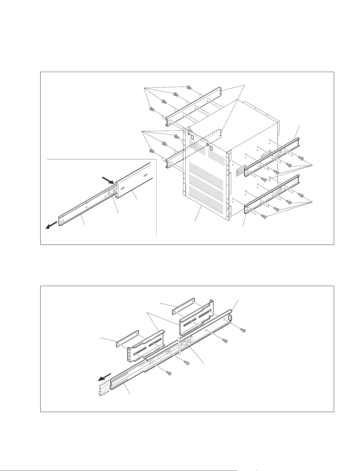
Procedures
1
1. Pull out the inner member while pressing the stopper of the rack mount rail RMM-18DV.
2. Attach the inner members to the unit using the 32 screws supplied with RMM-18DV.
1-9. Rack Mounting
Inner member
B 4x8
B 4x8
Outer member 1
Stopper
Inner members
Inner member
B 4x8
B 4x8
DVS-128
Inner member
3. Attach the brackets and the plate nuts (long) to the outer member 1 temporarily with the preparated
eight screws.
Slide the outer member 2 back-and-forth so that the screw holdes of the outer member 1 can be
seen.
Outer member
B 4x8
B 4x8
Plate nut (long)
Plate nut (long)
Brackets
Outer member 2
B 4x8
Outer member stopper
B 4x8
(Used for fixing the outer member 2.)
DVS-128E MMP1
1-11
Page 20
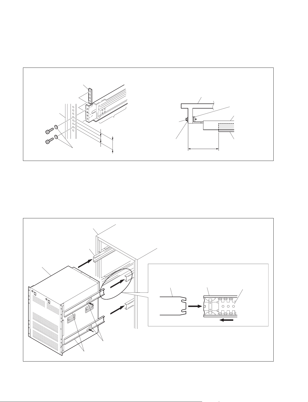
1-9. Rack Mounting
4. Temporarily attach the outer member assemblies to both sides of the rack using the eight screws and
the eight washers supplied with RMM-18DV. Adjust the installation position of the outer member to
meet the specification shown in the figure. After the adjustment, tighten the screws attached temporarily in the step (3).
— TOP VIEW —
Rack
Spec. :
+5
50
_0
Plate nut (small)
Bracket
Outer member 1
C 4x12
Rack
Plate nut (small)
W4
12.7
Outer member
assembly
44.45
C 4x12
W4
c
. Be sure to mount in the rack with three person or more.
. Be careful not to catch your finger or hand in rack nount rail.
5. Install the unit in the rack while releasing the stoppers of the inner member.
6. After confirming that the unit can be moved smoothly, tighten the screws attached temporarily in the
step (4).
Rack
DVS-128
1-12
Outer member 2
Inner members
Stoppers
. When housing the unit, shift the slide bearing as illustrated.
Inner member
Outer member 2
Slide bearing
DVS-128E MMP1
Page 21
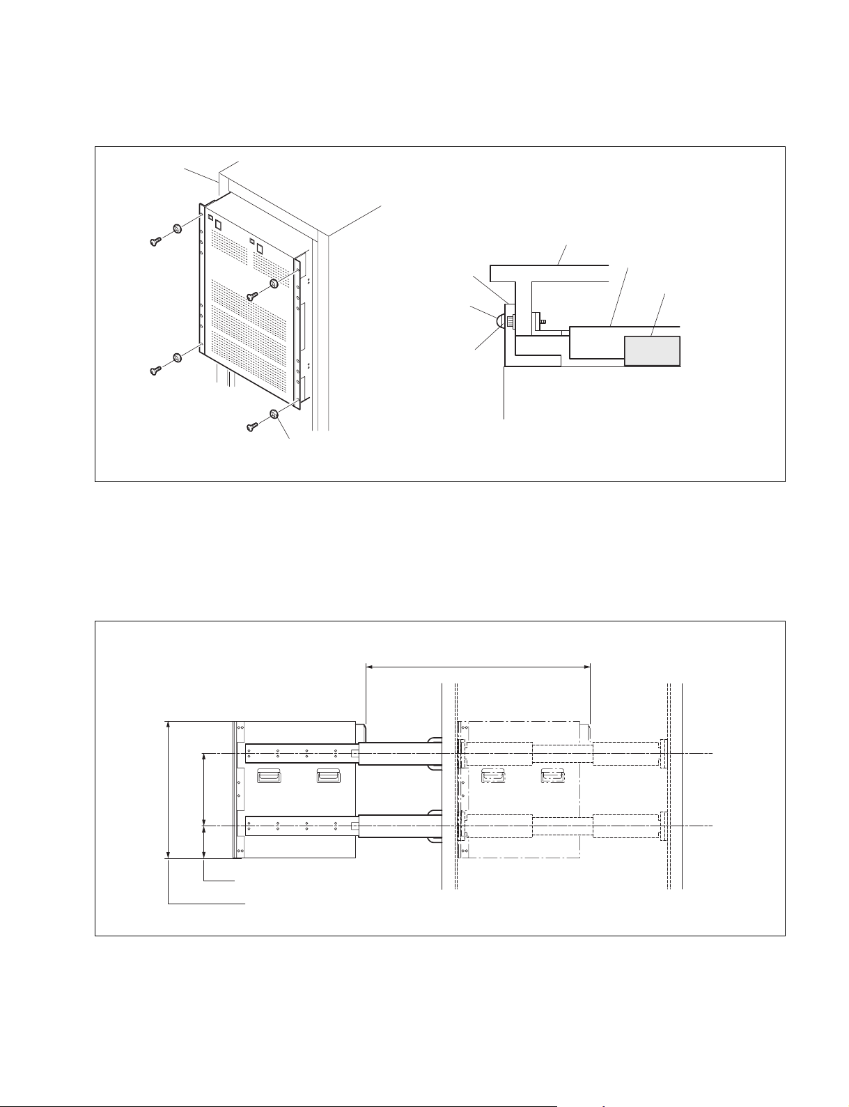
7. After installing the unit in the rack, fix the unit to the rack with the prepared four screws and the four
ornamental washers.
Rack
_ TOP VIEW _
Rack
1-9. Rack Mounting
Rack angle
RK 5x16
Ornamental washer
DVS-128
RK 5x16
Ornamental washer
Bracket
Outer member
c
Be sure to tighten the screws securing the rack angles. If they are not tightened, the DVS-128 slips and
drops off the rack that can result in physical injury. Be sure to tighten the screws after the DVS-128 is
mounted on a rack.
. When DVS-128 is mounted in a rack, the maximum traveling distance is illustrated below.
Maximum moving distance
569
DVS-128E MMP1
620 (14U)
132.2 355.5
Distance to slide rail center
Unit height when mounted in rack
Unit : mm
1-13
Page 22

1-10. Installation of Options
1-10-1. Installation of Plug-in Boards
1-10. Installation of Options
Describes the optional equipment for the DVS-128 series below.
Option Board
BKDS-12890 : Backup CPU board CPU-275
BKDS-12891 : Backup power unit LE-205, PS-539
BKDS-AA10 : Analog audio input board AAP-1, CNI-3/4, CN-1744
BKDS-AV10 : Analog video input board AVP-1, CNI-1/2, CN-1743
BKDS-DA10 : AES/EBU input board DAP-19, CNI-1/2, CN-1743
BKDS-AA11 : Analog audio output board AAP-2, ASW-55, LE-206, CNO-3M/3, JK-66
BKDS-AV11 : Analog video output board AVP-2, CNO-6/7, JK-66
BKDS-DA11 : AES/EBU output board DAP-22, CNO-1/2, JK-66
1-10-1. Installation of Plug-in Boards
DVS-128 series can be used for various systems, and its functions can be extended by selecting the
optional boards. Each plug-in board must be installed in the corresponding slot of DVS-128. Confirm
that all the boards are in the specified slots by referring to the following table.
For the details of how to install the plug-in board, refer to “1-10-3. Inserting/Pulling Out of Plug-in
Boards”.
m
1. Confirm that the connectors on each board are securely connected to the MB-820 board of the main
unit.
2. If the board is installed in an incorrect slot, a system error occurs. Then the system is not properly
activated.
Option Board name Slot (Flont side) Slot (Rear side)
BKDS-12890 CPU-275 CPU-B _
BKDS-AA10 AAP-1 INPUTS [1] to [4] _
CNI-3/4, CN-1744 (CN panel assembly) _ INPUTS [1] to [4]
BKDS-AV10 AVP-1 INPUTS [1] to [4] _
CNI-1/2, CN-1743 (CN panel assembly) _ INPUTS [1] to [4]
BKDS-DA10 DAP-19 INPUTS [1] to [4] _
CNI-1/2, CN-1743 (CN panel assembly) _ INPUTS [1] to [4]
BKDS-AA11 AAP-2, ASW-55, LE-206, JK-66 OUTPUTS [1] to [4] _
CNO-3M/3 (CN panel assembly) _ OUTPUTS [1] to [4]
BKDS-AV11 AVP-2, JK-66 OUTPUTS [1] to [4] _
CNO-6/7 (CN panel assembly) _ OUTPUTS [1] to [4]
BKDS-DA11 DAP-22, JK-66 OUTPUTS [1] to [4] _
CNO-1/2 (CN panel assembly) _ OUTPUTS [1] to [4]
1-14
DVS-128E MMP1
Page 23

INPUTS Slot
1-10. Installation of Options
1-10-1. Installation of Plug-in Boards
BKDS-AA10 BKDS-AV10 BKDS-DA10
OUTPUTS Slot
ASW-55
LE-206
CN-1744
AAP-1
JK-66
CNI-3
CNO-3
CNI-4
CNI-1
CN-1743
AVP-1
CNO-6
JK-66 JK-66
CNI-2
CN-1743
CNI-1
CNI-2
DAP-19
CNO-1
DVS-128E MMP1
AAP-2
BKDS-AA11
CNO-3M
AVP-2
BKDS-AV11
CNO-7
CNO-2
DAP-22
BKDS-DA11
1-15
Page 24

1-10. Installation of Options
1-10-2. Analog Audio Input and Output Boards
1-10-2. Analog Audio Input and Output Boards
BKDS-AA10
1. Channels supported by insertion slot
The supported channels differ from the insertion slot.
The following table shows relation between insertion slot numbers and channels.
Insertion slot No. Channel
INPUTS 1 1 to 32
INPUTS 2 33 to 64
INPUTS 3 65 to 96
INPUTS 4 97 to 128
2. Channels supported by analog audio input connector
The analog audio input connectors can input the 4 channel stereo signal per connector.
The channels that are supported by each connector are as follows.
Connector No. Channel
1 1 to 4 (L, R)
2 5 to 8 (L, R)
3 9 to 12 (L, R)
4 13 to 16 (L, R)
5 17 to 20 (L, R)
6 21 to 24 (L, R)
7 25 to 28 (L, R)
8 29 to 32 (L, R)
1-16
DVS-128E MMP1
Page 25

3. Pin assignment of analog audio input connector
The analog audio input connectors 1 through 8 have the same pin assignment.
The pin assignments of the connector 1 and connector 2 are shown below as an example.
1-10-2. Analog Audio Input and Output Boards
1-10. Installation of Options
<Connector 1>
FRAME GND
13
25
_ EXT VIEW _
Pin No. Signal Name
1 CH 1-L (HOT)
2 CH 1-L (COLD)
3 CH 1-R (GND)
4 CH 2-L (HOT)
5 CH 2-L (COLD)
6 CH 2-R (GND)
7 CH 3-L (HOT)
8 CH 3-L (COLD)
9 CH 3-R (GND)
10 CH 4-L (HOT)
11 CH 4-L (COLD)
12 CH 4-R (GND)
13 FRAME-GND
14 CH 1-L (GND)
15 CH 1-R (HOT)
16 CH 1-R (COLD)
17 CH 2-L (GND)
18 CH 2-R (HOT)
19 CH 2-R (COLD)
20 CH 3-L (GND)
21 CH 3-R (HOT)
22 CH 3-R (COLD)
23 CH 4-L (GND)
24 CH 4-R (HOT)
25 CH 4-R (COLD)
<Connector 2>
CH1-LCH2-LCH3-LCH4-L
1
14
FRAME GND
13
25
CH1-RCH2-RCH3-RCH4-R
_ EXT VIEW _
Pin No. Signal Name
1 CH 5-L (HOT)
2 CH 5-L (COLD)
3 CH 5-R (GND)
4 CH 6-L (HOT)
5 CH 6-L (COLD)
6 CH 6-R (GND)
7 CH 7-L (HOT)
8 CH 7-L (COLD)
9 CH 7-R (GND)
10 CH 8-L (HOT)
11 CH 8-L (COLD)
12 CH 8-R (GND)
13 FRAME-GND
14 CH 5-L (GND)
15 CH 5-R (HOT)
16 CH 5-R (COLD)
17 CH 6-L (GND)
18 CH 6-R (HOT)
19 CH 6-R (COLD)
20 CH 7-L (GND)
21 CH 7-R (HOT)
22 CH 7-R (COLD)
23 CH 8-L (GND)
24 CH 8-R (HOT)
25 CH 8-R (COLD)
CH5-LCH6-LCH7-LCH8-L
1
14
CH5-RCH6-RCH7-RCH8-R
DVS-128E MMP1
1-17
Page 26

1-10. Installation of Options
1-10-2. Analog Audio Input and Output Boards
4. Pin assignment of D-sub cable adapter
The BKDS-AA10 contains the 8 pieces of the D-sub cable adapter that are used for input using the pigtail cable.
The analog audio signal can be input by connecting CN101 on the D-sub cable adapter to the D-sub
connector on the BKDS-AA10 (analog audio input board) and a pigtail cable to CN1 through CN8 on the
D-sub cable adapter.
Pin assignment and connection between pins of the D-sub cable adapter are shown below.
1L
1R 2L 2R
123
12312
CN101
1
14
1
14
1L+
1L_
GND
1R+
1R_
GND
123
3
2R+
2R_
GND
GND
2L+
2L_
25
13
ANALOG
AUDIO
INPUT
D-sub 25 pin
(Female)
25
13
D-sub 25 pin
(Male)
CN1 CN2
3L
123
3L+
3L_
GND
CN5 CN6
3R 4L 4R
12312
3R+
3R_
GND
4L+
CN3 CN4
123
3
4R+
4R_
4L_
GND
CN7 CN8
GND
CN1 through CN8 are the 3P terminal.
1-18
DVS-128E MMP1
Page 27

BKDS-AA11
1. Channels supported by insertion slot
The supported channels differ from the insertion slot.
The following table shows relation between insertion slot numbers and channels.
Insertion slot number Channel
OUTPUTS 1 1 to 32
OUTPUTS 2 33 to 64
OUTPUTS 3 65 to 96
OUTPUTS 4 97 to 128
2. Channels supported by analog audio output connector
The BKDS-AA11 can output the 4 channel stereo signal per connector.
The analog audio output signals that are supported by each connector are as follows.
Connector number Channel
1 1 to 4 (L, R)
2 5 to 8 (L, R)
3 9 to 12 (L, R)
4 13 to 16 (L, R)
5 17 to 20 (L, R)
6 21 to 24 (L, R)
7 25 to 28 (L, R)
8 29 to 32 (L, R)
1-10-2. Analog Audio Input and Output Boards
1-10. Installation of Options
n
The analog audio monitor output connector can output the analog audio signal of the
desired channel among the 32 channels.
DVS-128E MMP1
1-19
Page 28

1-10. Installation of Options
1-10-2. Analog Audio Input and Output Boards
3. Pin assignment of analog audio input connector
The analog audio output connectors 1 through 8 have the same pin assignment.
The pin assignments of the connector 1 and connector 2 are shown below as an example.
<Connector 1>
FRAME GND
13
25
_ EXT VIEW _
Pin No. Signal Name
1 CH 1-L (HOT)
2 CH 1-L (COLD)
3 CH 1-R (GND)
4 CH 2-L (HOT)
5 CH 2-L (COLD)
6 CH 2-R (GND)
7 CH 3-L (HOT)
8 CH 3-L (COLD)
9 CH 3-R (GND)
10 CH 4-L (HOT)
11 CH 4-L (COLD)
12 CH 4-R (GND)
13 FRAME-GND
14 CH 1-L (GND)
15 CH 1-R (HOT)
16 CH 1-R (COLD)
17 CH 2-L (GND)
18 CH 2-R (HOT)
19 CH 2-R (COLD)
20 CH 3-L (GND)
21 CH 3-R (HOT)
22 CH 3-R (COLD)
23 CH 4-L (GND)
24 CH 4-R (HOT)
25 CH 4-R (COLD)
<Connector 2>
CH1-LCH2-LCH3-LCH4-L
1
14
FRAME GND
13
25
CH1-RCH2-RCH3-RCH4-R
_ EXT VIEW _
Pin No. Signal Name
1 CH 5-L (HOT)
2 CH 5-L (COLD)
3 CH 5-R (GND)
4 CH 6-L (HOT)
5 CH 6-L (COLD)
6 CH 6-R (GND)
7 CH 7-L (HOT)
8 CH 7-L (COLD)
9 CH 7-R (GND)
10 CH 8-L (HOT)
11 CH 8-L (COLD)
12 CH 8-R (GND)
13 FRAME-GND
14 CH 5-L (GND)
15 CH 5-R (HOT)
16 CH 5-R (COLD)
17 CH 6-L (GND)
18 CH 6-R (HOT)
19 CH 6-R (COLD)
20 CH 7-L (GND)
21 CH 7-R (HOT)
22 CH 7-R (COLD)
23 CH 8-L (GND)
24 CH 8-R (HOT)
25 CH 8-R (COLD)
CH5-LCH6-LCH7-LCH8-L
1
14
CH5-RCH6-RCH7-RCH8-R
1-20
DVS-128E MMP1
Page 29

1-10-2. Analog Audio Input and Output Boards
4. Pin assignment of D-sub cable adapter
The BKDS-AA11 contains the 8 pieces of the D-sub cable adapter that are used for output using the pigtail cable.
The analog audio signal can be output by connecting CN101 on the D-sub cable adapter to the D-sub
connector on the BKDS-AA11 (analog audio output board) and a pigtail cable to CN1 through CN8 on
the D-sub cable adapter.
Pin assignment and connection between pins of the D-sub cable adapter are shown below.
1L
1R 2L 2R
123
12312
CN101
1
14
1
14
1L+
1L_
GND
1R+
1R_
GND
123
3
2R+
2R_
GND
GND
2L+
2L_
1-10. Installation of Options
25
13
ANALOG
AUDIO
25
13
D-sub 25 pin
(Male)
CN1 CN2
3L
123
3L+
3L_
GND
CN5 CN6
3R 4L 4R
12312
3R+
3R_
GND
4L+
CN3 CN4
123
3
4R+
4R_
4L_
GND
CN7 CN8
GND
OUTPUT
D-sub 25 pin
(Female)
CN1 through CN8 are the 3P terminal.
Hybrid Routing
To implement the hybrid routing ensuring the high quality signal characteristics, the sixteen JK-66 boards
are mounted on each output board of the DVS-128 series.
The JK-66 board is a connection switch board that turns on and off the matrix input (128 input lines) in
each output board. The JK-66 boards are set to ON when the DVS-128 is shipped from the factory.
When setting up both analog audio and analog video system in the DVS-128, the JK-66 boards of the
input channel to which the analog video signal is impressed should be removed from the matrix input
block of the analog audio output board.
When setting up either analog audio or analog video system, it is not required to remove the JK-66
boards.
When installing the DVS-128, remove the JK-66 boards accordance with the desired system configuration in order to prevent occurrence of interference between the different signal formats.
Each of the JK-66 board contains the switches for eight channels as shown below. The sixteen JK-66
boards configure a switch for 128 channels.
The JK-66 boards are located near the connectors (from which connection to the mother board is established) of each output board. The four JK-66 boards are located to the input channels of 1 to 32, 33 to 64,
97 to 128 and 65 to 96 when viewed from the left.
DVS-128E MMP1
1-21
Page 30

1-10. Installation of Options
1-10-2. Analog Audio Input and Output Boards
DVS-128 Signal connection diagram
Various input boards
Slot
INPUTS 1
32
BKDS-xx10
1 to 32ch
32 32 32 32
INPUTS 2
BKDS-xx10
33 to 64ch
32
Slot
32
Slot
INPUTS 3
32
BKDS-xx10
65 to 96ch
32
INPUTS 4
BKDS-xx10
97 to 128ch
32
Slot
32
32323232
32
32
32
32
32
JK-66
JK-66
JK-66
JK-66
JK-66
JK-66
JK-66
JK-66
JK-66
JK-66
JK-66
JK-66
JK-66
JK-66
65 to 96ch
98 to 128ch33 to 64ch1 to 32ch
MATRIX
128 x 32
32
OUTPUT
BKDS-xx11
Slot
OUTPUTS 1
xx:AA/DA/AV
TM-39
x 4
TM-39
x 4
MOTHER BOARD MB-820
TM-39
x 4
TM-39
x 4
JK-66
JK-66
Various output boards
(Same as above)
(Same as above)
(Same as above)
32323232
JK-66 : Connection switches board
TM-39 : Termination resistors board
Slot
OUTPUTS 2
Slot
OUTPUTS 3
Slot
OUTPUTS 4
1-22
DVS-128E MMP1
Page 31

1-10-3. Inserting/Pulling Out of Plug-in Boards
1-10. Installation of Options
1-10-3. Inserting/Pulling Out of Plug-in Boards
c
To avoid shock hazards and/or damage to the mounted circuit boards, be sure to turn off the power switch
before inserting or pulling out the plug-in boards.
Front Panel Side
1. Unscrew the four screws, then remove the front panel.
2. Unscrew the four screws, then remove the two board retainers.
PSW 3
PSW 3x6
Board retainer
x6
PSW 3x6
Board retainer
PSW 3x6
DVS-128E MMP1
1-23
Page 32

1-10. Installation of Options
1-10-3. Inserting/Pulling Out of Plug-in Boards
Installation
1. Insert the plug-in board along the board guide rail while pressing the eject levers to 1 position as
shown in the figure.
2. Connect the plug-in board to the connectors on the mother board by pressing the eject levers in the
direction of the arrow 2.
n
Insert the plug-in board with an equal force for both eject levers.
Eject levers
1
1
2
2
Plug-in board
3. Install the two board retainers in the reverse order of the steps 1 and 2.
Removal
1. Open the eject levers of the plug-in board in the direction of arrow 1.
2. Pull out the plug-in board from the unit.
n
Pull out the plug-in board with an equal force for both eject levers.
MB-820 board
Board guide rail
1-24
DVS-128E MMP1
Page 33

Rear Panel Side
1. Unscrew the two screws (PWH 3x5), then remove the blank panel.
PWH 3x5
Brank panel
1-10-3. Inserting/Pulling Out of Plug-in Boards
1-10. Installation of Options
PWH 3x5
Installation
In the case of BKDS-AA11/AV11/DA11 :
1. Insert the plug-in board vertical along the board guide rail.
In the case of BKDS-AA10/AV10/DA10 :
1. Insert the plug-in board vertical along the board guide rail while pressing the eject levers to 1
position as shown in the figure.
2. Connect the plug-in board to the connectors on the mother board by pressing the eject levers in the
direction of the arrow 2.
PWH 3x5
PWH 3x5
Eject lever
2
Board guide rail
DVS-128E MMP1
Plug-in board
(BKDS-AA11, AV11, DA11)
PWH 3x5
2
Board guide rail
PWH 3x5
Plug-in board
(BKDS-AA10, AV10, DA10)
1-25
Page 34

1-10. Installation of Options
1-10-3. Inserting/Pulling Out of Plug-in Boards
Removal
1. Disconnect the cables that are connected to the plug-in board which you want to remove.
2. Unscrew the two screws (PWH 3x5).
3. In the case of BKDS-AA11/AV11/DA11 :
(1) Pull out the plug-in board while holding the connectors of the board.
PWH 3x5
Board guide rail
Plug-in board
(BKDS-AA11, AV11, DA11)
PWH 3x5
In the case of BKDS-AA10/AV10/DA10 :
(1) Open the eject lever in the direction of the arrow 1.
(2) Pull out the plug-in board from the DVS-128.
PWH 3x5
Eject lever
1
1
1-26
Board guide rail
Plug-in board
(BKDS-AA10, AV10, DA10)
PWH 3x5
DVS-128E MMP1
Page 35

1-10-4. Installation of Backup Power Supply Unit (BKDS-12891)
1-10-4. Installation of Backup Power Supply Unit (BKDS-12891)
w
To avoid shock hazards, be sure to turn off the power switch, then turn off the breaker at the outside of
the DVS-128 or unplug the power cord when installing the BKDS-12891.
1. Turn off the main power of the DVS-128.
2. Remove the front panel. (Refer to section “2-1. Removal/Installation of Front Panel”.)
3. Remove the blank panel of the installation position (as shown below) to which the BKDS-12891 is
going to be installed.
4. Properly insert the BKDS-12891 to the installation position.
5. Fix the BKDS-12891 to the DVS-128 with the four screws that had fixed the blank panel.
6. Turn on the power switches of the BKDS-12891 and the DVS-128.
Blank panel
1-10. Installation of Options
PSW 4x8
PSW 4x8
PSW
4x8
BKDS-12891
PSW 4x8
DVS-128E MMP1
1-27
Page 36

1-11. Setting the On-Board Switches and Explanation of LEDs
1-11-1. CPU-275 board (DVS-128/BKDS-12890)
1-11. Setting the On-Board Switches and
Explanation of LEDs
1-11-1. CPU-275 board (DVS-128/BKDS-12890)
BCDEFGHJ
A
D11
D13
D15
D18
D1
D5
D2
D19
D1 (A-2): ACTIVE LED
The LED turns on when the bus can communicate with
outside. The LED of the board in operation turns on when
the CPU-275 board for backup is installed.
D2 (A-2): RUN LED
The LED turns on when the CPU runs normally.
D5 (A-2): PRIMARY LED
The LED turns on when this board is assigned to a primary
station.
D9 (J-2):
The LED turns on when the PS1 (J1) fuse blows.
D10 (A-1): S-BUS TX LED
The LED turns on for about 0.15 second when data is output
from the REMOTE 1 connector to the S-BUS data link. It
turns on continuously when the DVS-128 is used as the
primary station, and turns on only when it is operated
internally if the DVS-128 is used as the secondary station.
D11 (A-1): S-BUS RX LED
This LED turns on for about 0.15 second when the DVS128 receives data that is addressed to the local station from
the S-BUS data link via the REMOTE 1 connector.
D12 (A-1): MONITOR S-BUS TX LED
The LED turns on for about 0.15 second when data is output
from the REMOTE 4 connector to the MONITOR S-BUS
data link. It turns on continuously when the DVS-128 is used
as the primary station, and turns on only when it is operated
internally if the DVS-128 is used as the secondary station.
D13 (A-1): MONITOR S-BUS RX LED
This LED turns on for about 0.15 second when the DVS128 receives data that is addressed to the local station from
the MONITOR S-BUS data link via the REMOTE 4
connector.
1-28
S1
CN3
CN4
CN5
S5
IC26
S2
S3
S4
D10
D12
D14
D17
++
+5 V LED
++
CN6
COR1
D9
S6
S8
S7
(Side A/component side)
D14 (A-1): 422-A TX LED
This LED turns on for about 0.15 second when data is output
to the RS-422 line of the “A” connector of REMOTE 2.
D15 (A-1): 422-A RX LED
This LED turns on for about 0.15 second when the DVS-
1
128 receives data from the RS-422 line of the “A” connec-
2
tor of REMOTE 2.
3
D17 (A-2): 422-B TX LED
4
This LED turns on for about 0.15 second when data is output
to the RS-422 line of the “B” connector of REMOTE 2.
5
6
D18 (A-2): 422-B RX LED
This LED turns on for about 0.15 second when the DVS-
7
128 receives data from the RS-422 line of the “B” connector of REMOTE 2.
D19 (A-2): ERROR LED
This LED turns when an error occurs. It turns on also at
occasions such as a cross-point error, fan stop, ROM/RAM
error, disconnection of S-BUS line (detected whether the line
is terminated by 75 Z or not) and when the backup CPU or
backup power supply is installed, but not operating.
IC26 (A-4): ERROR No. display on 7-segment LED
The error number is displayed when an abnormality occurs.
The contents of the respective errors are shown in the
following table. When two or more errors occur at the same
time, the error No. of the first error is kept on display.
Error No. Content
00 Normal run
27 The S-BUS line is disconnected. (detected
40 Cross-point error
50 Battery backup error
60 Sync signal error
70 Fan error
80 ROM/RAM error
FF The error display appears temporarily then
whether the line is terminated by 75 Z or not)
Existence/absence detected at the input and
output terminals do not agree.
This error is displayed when the contents of the
backup data cannot be guaranteed.
The reference video signal cannot be detected
even though the sync mode (SYN) is selected by
switch S4-1 on the CPU-275 board.
This indicates that the fan attached to the DVS128 has stopped.
An error occurs when the ROM check-sum and
the RAM writing test are performed immediately
after reset.
The error occurs only once when ROM version
upgrading is performed. However, the CPU-275
board is judged defective if the error display does
not change even when the system is reset.
disappears when the system is reset. The CPU275 board is judged defective if the error display
does not change even when the system is reset.
DVS-128E MMP1
Page 37

1-11. Setting the On-Board Switches and Explanation of LEDs
1-11-1. CPU-275 board (DVS-128/BKDS-12890)
S1 (A-7): TEST rotary switch
This switch is used for adjustment in the factory. Never
change the setting.
0
1
D
C
B
Factory setting
2
3
4
A
8
S2 (A-5): STATION ID setting switch
8-pin DIP switch
This switch is used to set the station address of the DVS128 in the data link when the DVS-128 is connected to the
S-BUS data link using the REMOTE 1 connector.
S4-2: The station address is fixed to “1” when the S/P
switch is set to the “OPEN” position (primary station
position). When the switch S4-2: S/P switch is set to the
“CLOSE” position (secondary station position), set the
station address to any positions other than 0, 1, and 255.
The address must be selected so that the station address is
not duplicated with the address of other secondary stations.
1
1
0
2
(1
Bit
3456
2
4 8 16 32
8
7
64 128)
Setting example
Bit 12345678
Station address
8 00010000
50 01001100
200 00010011
OPEN
S3 (A-6):
8-pin DIP switch
Bit 1: 422/S-BUS switch
This switch selects which of the REMOTE 1 (S-BUS)
command or REMOTE 2 (RS-422) command has priority.
OPEN (upper position): REMOTE 1 (S-BUS) has
priority.
CLOSE (lower position):REMOTE 2 (RS-422) has
priority.
Bit 2: 128/32 switch
This switch selects either 128 bytes or 32 bytes for the SBUS table size that the primary station outputs.
OPEN (upper position): 32 bytes
CLOSE (lower position):128 bytes
Bit 3: TEST switch
This switch is used for adjustment in the factory. Never
change the setting.
Bit 4: REMOTE 1 (S-BUS) baud rate selector switch
This switch is used to select either 312.5 Kbps or
1250 Kbps baud rate for the S-BUS data link that is
connected to REMOTE 1.
When the 1250 Kbps baud rate is selected, other equipment that is connected to the same S-BUS data link must
be set to support the 1250 Kbps baud rate. Also, when the
1250 Kbps baud rate is selected, a 75 Z terminator must be
connected to both ends of the cable. As a result, the cable
disconnection test can no longer be performed, but the
response speed is higher.
OPEN (upper position): 1250 Kbps
CLOSE (lower position): 312.5 Kbps
Bits 5 to 8: Not used.
Use the switches with the default setting CLOSE (lower
position) as shipped from the factory.
12345678
Factory setting ( indicates the switch lever posion.)
DVS-128E MMP1
OPEN
12345678
Factory setting ( indicates the switch lever posion.)
1-29
Page 38

1-11. Setting the On-Board Switches and Explanation of LEDs
1-11-1. CPU-275 board (DVS-128/BKDS-12890)
S4 (A-6):
8-pin DIP switch
Bit 1: SYNC/ASYNC switch
This switch selects whether the input video signals are
switched synchronously or asynchronously with the
reference video signal that is input to the REF IN connector.
The DVS-128 operates asynchronously even if this switch
is set to SYNC, unless the reference video signal is input to
the REF IN connector. In this case, this is detected as an
error.
OPEN (upper position): Asynchronous mode
CLOSE (lower position): Synchronous mode
Bit 2: S/P switch
This switch is used to selects whether the DVS-128
operates as a primary station or a secondary station when it
is connected to the S-BUS data link with the REMOTE 1
connector.
OPEN (upper position): Operates as a primary
station
CLOSE (lower position): Operates as a secondary
station
Bit 3: TERM/ISR switch
This switch selects whether the REMOTE 3 is used in the
terminal mode/data backup mode for setting or in the ISR
mode.
OPEN (upper position): ISR mode
CLOSE (lower position): Terminal mode/data backup
mode for setting
S5 (A-3): RESET switch
This is the hardware reset switch of the CPU-275 board.
When this switch is pressed, the CPU-275 board operates
in the same manner as the main power is turned on.
S6 (G-5): S-BUS local CPU reset switch
This is the reset switch for the S-BUS local CPU of the
CPU-275 board. When this switch is pressed, the S-BUS
local CPU only is reset.
S7 (F-7): Not used.
4-pin DIP switch
Use the switches with the default setting CLOSE (lower
position) as shipped from the factory.
OPEN
1234
Factory setting ( indicates the switch lever posion.)
S8 (G-6): MONITOR S-BUS local CPU reset switch
This is the reset switch for the MONITOR S-BUS local
CPU of the CPU-275 board. When this switch is pressed,
the MONITOR S-BUS local CPU only is reset.
COR1 (C-1): Jumper terminal for connecting a
debugger
This terminal is set in the GHS ON position when a
debugger (GHS) is connected to CN6 for debugging. Set
this terminal in the default position when shipped from the
factory during normal operation.
Bit 4: 38.4/9.6 switch
This switch is used to select whether the RS-232C transfer
speed is 38400 bps or 9600 bps when REMOTE 3 of the
DVS-128 is used in the terminal mode (S4-3 is in the
TERM position).
OPEN (upper position): 9600 bps
CLOSE (lower position): 38400 bps
Bits 5 to 8: Not used.
Use the switches with the default setting CLOSE (lower
position) as shipped from the factory.
OPEN
12345678
Factory setting ( indicates the switch lever posion.)
1-30
GHS ON
Factory setting
CN3 (A-2):
This is a connector for debug monitoring of the S-BUS
local CPU and for program transfer through RS-232C.
CN4 (A-3):
This is a connector for debug monitoring of the S-BUS
local CPU and for program transfer through RS-232C.
CN5 (A-3):
This is an RS-232C for program transfer.
CN6 (C-1):
This is an RS-232C for connecting a debugger (GHS).
DVS-128E MMP1
Page 39

1-11. Setting the On-Board Switches and Explanation of LEDs
1-11-2. AAP-1 board (BKDS-AA10)
1-11-2.AAP-1 board (BKDS-AA10)
D107
1
D198
S65
D108
D119
D120
D131
D132
D143
D144
D155
D156
D167
D168
D181
D169
D189
D190
D29
D30
D31
D32
D61
D62
D63
D64
D93
D94
D95
D96
D28
D50
D88
D89
S1S2S33
S15S9S47
S56
S55
S62
S61
S24
S30
S23
S29
S34
S41
S54
S60
S3
S16
S53
S59
S4
S10
S22
S28
D258D262
S35
S36
S37
S5
S6
2
S48
S42
S11
S12
S43
2
S21
S52
S51
S20
S19
2
S27
S58
S64
S26
S32
2
(Side A/component side)
S38
S44
S50
S57
S7
S13
S49
S63
D192
S8
S14
S18
S25
S39
S45
S17
S31
123456789101112
S40
S46
11
1 Analog audio signal input LED
11
Existence/absence of the analog audio input signal at
A
B
the analog audio signal input terminal is detected. The
LED turns on in green when the signal of _24 dBm
(when the reference input level of +4 dB is input), and
turns off when the input signal is not connected or the
C
D
E
F
G
H
J
input signal has a low level.
D198 (E-12): WORD-SYNC EXIST LED
Existence/absence of the sync reference signal is displayed.
The LED turns on in green when the selected input signal
is input to the AAP-1 board.
D192, D258, D262: IC link breakdown LED
The LED turns on in red when the IC link is broken, and is
turned off normally.
K
L
M
PS1 → D262
PS2 → D258
PS3 → D192
22
2 S1 to S64: Analog audio 600
22
ZZ
Z termination switch
ZZ
These are the 600 Z termination ON/OFF switches of
the input analog signal.
ON: Terminated in 600 Z
OFF: High impedance
OFF ON
Factory setting
( indicates the switch lever posion.)
S65 (E-12): REF SELECT switch
This switch selects the reference signal to which the
internal clock of the board is locked.
A: The internal clock locks to the audio word sync signal
or to the reference signal that is input to “A” on the
rear panel of the DVS-128.
B: The internal clock locks to the audio word sync signal
or to the reference signal that is input to “B” on the
rear panel of the DVS-128.
AB
Factory setting
( indicates the switch lever posion.)
n
The reference sync signal (A/B) that is selected by the
above switch S65, must also be selected by the output
board (S5/ASW-55 board or S1/DAP-22 board). If
different reference sync signals are selected by the input
and output boards individually, the DVS-128 will not work
normally.
DVS-128E MMP1
1-31
Page 40

1-11. Setting the On-Board Switches and Explanation of LEDs
1-11-3. AAP-2 board (BKDS-AA11)
1-11-4. LE-206 board (BKDS-AA11)
1-11-3. AAP-2 board (BKDS-AA11)
13
1415
D999
D998
D979
D978
D1001
D1000
D997
D996
D982
(Side A/component side)
1-11-4. LE-206 board (BKDS-AA11)
D443
D444
D445
AFGHBCDE
D446
D475
D476
D477
D478
D101
1
2
3
4
123456789101112
A
B
C
D
E
F
G
H
J
K
L
M
N
P
Q
R
S
D229
D230
D231
D232
D261
D262
D263
D264
D293
D294
D295
D296
D325
D326
D327
D328
D379
D380
D381
D382
D411
D412
D413
D414
D104
1
11
1 Analog audio signal output LED
11
D102
(Side A/component side)
Existence/absence of the analog audio output signal at
the analog audio signal output terminal is detected.
The LED turns on in green when the signal of
_24 dBm (when the reference input level of +4 dB is
output), and turns off when the output signal is not
output or the output signal has a low level.
D104 (F-4): WORD-SYNC EXIST LED
The LED turns on in green when the selected audio word
sync signal is input to the BKDS-AA11.
D101, 102 : IC link breakdown LED
The LED turns on in red when the IC link (PS101, 102) is
broken, and is turned off normally.
D979, 978, 982, 996 to 1001 : IC link breakdown LED
The LED turns on in red when the IC link is broken, and is
turned off normally.
PS981 → D982
PS984 → D978
PS985 → D979
PS986 → D996
PS987 → D997
PS988 → D998
PS989 → D999
PS990 → D1000
PS991 → D1001
1-32
DVS-128E MMP1
Page 41

0
2
3
5
6
7
1
8
Factory setting
4
9
A
B
C
0
F
E
D
1-11. Setting the On-Board Switches and Explanation of LEDs
1-11-5. ASW-555 board (BKDS-AA11)
1-11-5. ASW-55 board (BKDS-AA11)
D201
S2
S5
D3
D4
S1
(Side A/component side)
D3, D4: CPU operation check LED
ABCDEFGH
1
2
3
S3
4
5
6
The green LED (D4) only turns on when the CPU on the
ASW-55 board is operating normally. The red LED (D3)
only turns on when the CPU operation is abnormal.
D201 (G-1) : IC link breakdown LED
The LED turns on in red when the IC link (PS200) is
broken, and is turned off normally.
S1 (D-6): RESET switch
This is the reset switch for the CPU on the AAP-2 board.
It does not reset the CPU-275 board.
This switch is not used normally.
S2, S3: TEST mode setting switch
These switches are not used normally.
S5 (E-6): REF SELECT switch
This switch selects the reference signal to which the
internal clock of the board is locked.
A: The internal clock locks to the audio word sync signal
or to the reference signal that is input to “A” on the
rear panel of the DVS-128.
B: The internal clock locks to the audio word sync signal
or to the reference signal that is input to “B” on the
rear panel of the DVS-128.
AB
Factory setting
( indicates the switch lever posion.)
n
The reference sync signal (A/B) that is selected by the
above switch S5, must also be selected by the output board
(S65/AAP-1 board or S1/DAP-19 board). If different
reference sync signals are selected by the input and output
boards individually, the DVS-128 will not work normally.
DVS-128E MMP1
1-33
Page 42

1-11. Setting the On-Board Switches and Explanation of LEDs
1-11-6. DAP-19 board (BKDS-DA10)
1-11-6. DAP-19 board (BKDS-DA10)
D3201
D3202
D3203
D3204
D3205
D3206
D3207
D3208
1
D3209
D3210
D3211
D3212
D3213
D3214
D3215
D3216
D1
D3217
D3218
S1
D3219
D3220
D3221
D3222
D3223
D3224
D3225
D3226
D3227
D3228
D3229
D3230
D3231
D3232
(Side A/component side)
D4100
11
1 D3201 to D3232: INPUT EXIST LED
11
Existence/absence of the AES/EBU format digital
123456789101112
A
B
audio input signal is displayed.
The LED turns on in green when the input signal is
present.
D3201: INPUT 1
C
D
E
F
D1 (E-12): WORD-SYNC EXIST LED
Existence/absence of the audio word sync signal is dis-
G
played.
H
D3202: INPUT 2
↓
D3231: INPUT 31
D3232: INPUT 32
The LED turns on in green when the audio word sync
J
signal is present.
K
D4100 (A-2): IC link breakdown LED
L
The LED turns on in red when the IC link (PS4100) is
broken, and is turned off normally.
M
S1 (E-12): REF SELECT switch
This switch selects the reference signal to which the
internal clock of the board is locked.
A: The internal clock locks to the audio word sync signal
or to the reference signal that is input to “A” on the
rear panel of the DVS-128.
B: The internal clock locks to the audio word sync signal
or to the reference signal that is input to “B” on the
rear panel of the DVS-128.
1-34
AB
Factory setting
( indicates the switch lever posion.)
n
The reference sync signal (A/B) that is selected by the
above switch S1, must also be selected by the output board
(S5/ASW-55 board or S1/DAP-22 board). If different
reference sync signals are selected by the input and output
boards individually, the DVS-128 will not work normally.
DVS-128E MMP1
Page 43

1-11. Setting the On-Board Switches and Explanation of LEDs
0
2
3
5
6
7
1
8
Factory setting
4
9
A
B
C
0
F
E
D
1-11-7. DAP-22 board (BKDS-DA11)
1-11-7. DAP-22 board (BKDS-DA11)
101112
D1
D2
D3
D4
D5
D6
D7
D8
1
D501
D502
11
1 D1 to D32: OUTPUT EXIST LED
11
D9
D10
D11
D12
D13
D14
D15
D16
D33
D17
D18
S1
D19
D20
D21
D22
D23
D24
D25
S2
D26
D27
S503
D28
D29
D30
D31
D32
S502
89
Existence/absence of the AES/EBU format digital
audio output signal is displayed.
The LED turns on in green when the output signal is
present.
D1: OUTPUT 1
D2: OUTPUT 2
↓
D31: OUTPUT 31
D32: OUTPUT 32
D33 (E-12): WORD-SYNC EXIST LED
Existence/absence of the audio word sync signal is displayed.
The LED turns on in green when the audio word sync
signal is present.
4
567
123
D600
(Side A/component side)
D501 (G-12): ERROR LED
The LED turns on in red when operation of the DAP-22
board is abnormal, and is turned off normally.
A
D502 (G-12): RUN LED
B
The LED turns on in green when the control CPU on the
C
DAP-22 board operates normally, and turns off when the
CPU is not operating.
D
E
D600 (A-2): IC link breakdown LED
The LED turns on in red when the IC link (PS600) is
F
broken, and is turned off normally.
G
S1 (F-12): REF SELECT switch
H
This switch selects the reference signal to which the
J
internal clock of the board is locked.
A: The internal clock locks to the audio word sync signal
K
L
M
or to the reference signal that is input to “A” on the
rear panel of the DVS-128.
B: The internal clock locks to the audio word sync signal
or to the reference signal that is input to “B” on the
rear panel of the DVS-128.
AB
Factory setting
( indicates the switch lever posion.)
n
The reference sync signal (A/B) that is selected by the
above switch S1, must also be selected by the output board
(S65/AAP-1 board or S1/DAP-19 board). If different
reference sync signals are selected by the input and output
boards individually, noise may be generated or the signal
may be muted.
S2 (H-12): RESET switch
This is the reset switch for the entire DAP-22 board. It
does not reset the CPU-275 board.
This switch is not used normally.
S502, S503: Test mode setting switch
These switches are not used normally.
DVS-128E MMP1
1-35
Page 44

1-11. Setting the On-Board Switches and Explanation of LEDs
1-11-8. AVP-1 board (BKDS-AV10)
1-11-8.AVP-1 board (BKDS-AV10)
D7002
D7003
D7004
D7005
D7006
D7007
D7008
D7009
1
D7001
S7000
S7001
S7002
D7010
D7011
D7012
D7013
D7014
D7015
D7016
D7017
D7018
D7019
D7020
D7021
D7022
D7023
D7024
D7025
D7026
D7027
D7028
D7029
D7030
D7031
D7032
D7033
(Side A/component side)
11
1 D7002 to D7033: INPUT EXIST LED
11
Existence/absence of the analog video input signal is
displayed.
The LED turns on in green when the input signal is present.
n
Because the input signal is detected from the sync signal
that is contained in the input signal, this LED will not
work correctly if an input signal without sync is input.
D7001 (E-8): REF EXIST LED
Existence/absence of the video reference signal is displayed.
D8000, D8001: IC link breakdown LED
The LED turns on in red when the IC link (PS800,
PS8001) is broken, and is turned off normally.
S7000 (F-8): REF SELECT switch
A: The clamp pulse of the reference mode is generated
from the reference signal that is input to “A” on the
DVS-128 rear panel, and is used for clamping.
B: The clamp pulse of the reference mode is generated
from the reference signal that is input to “B” on the
DVS-128 rear panel, and is used for clamping.
AB
Factory setting
( indicates the switch lever posion.)
12345678
D8001D8000
S7001 (G-8): Clamp mode select switch
8-pin DIP switch
The input signals are clamped in units of eight channels
A
using the following modes.
B
. Self mode
C
The respective input signals are clamped by their own
signals. This mode is valid for all video signals except
D
E
for the color difference signal.
. Reference mode
F
G
H
The respective input signals are clamped by the clamp
signal that is generated from the reference signal. This
mode is valid only when the input signal is sync-locked
with the reference signal. The reference signal needs to
be input for this mode.
J
. Direct mode
K
L
The DC levels of the respective input signals are maintained as they are and are output. This mode works
effectively even when a signal having no SYNC signal
M
such as a color difference signal is input. This mode can
be used for all types of video signal.
When the HDTV signal is used, be sure to select this
mode.
8 bits are grouped into the following four blocks. Each block
selects the clamp mode individually in units of eight channels.
Bit 1, 2: Channels 1 to 8
Bit 3, 4: Channels 9 to 16
Bit 5, 6: Channels 17 to 24
Bit 7, 8: Channels 25 to 32
ON
Factory setting
BIT No.
12345678
12121212
1~8 17~249~16 25~32
CH
( indicates the
switch lever posion.)
CLAMP
SELF
REF
DIRECT
S7002 (H-8): SIGNAL EXIST INTERFACE switch
ON: When the video signal with sync added.
OFF: When the video signal without sync (such as color
difference signal). When OFF is selected, data (with
signal) in which the existence/absence detected data
of all input signals is fixed, is supplied to the
motherboard from this switch.
SW
12
OFF
OFF
OFF
ON
ON
_
1-36
ON OFF
Factory setting
DVS-128E MMP1
Page 45

1-11. Setting the On-Board Switches and Explanation of LEDs
0
2
3
5
6
7
1
8
Factory setting
4
9
A
B
C
0
F
E
D
1-11-9. AVP-2 board (BKDS-AV11)
1-11-9. AVP-2 board (BKDS-AV11)
A
D2305 D2304
D2302
B
1
C
D2303
D
E
F
G
S2000
H
J
K
L
S2104
M
D2120
D2121
S2102
N
S2103
P
Q
R
D2301
D1901
D1902
D1903
D1904
D1905
D1906
D1907
D1908
D1909
D1910
D1911
D1912
D1913
D1914
D1915
D1916
D1917
D1918
D1919
D1920
D1921
D1922
D1923
D1924
D1925
D1926
D1927
D1928
D1929
D1930
D1931
D1932
(Side A/component side)
D2120 (M-1): ERROR LED
The LED turns on in red when operation of the AVP-22
1110987654321
board is abnormal, and is turned off normally.
D2121 (M-1): RUN LED
The LED turns on in green when the control CPU on the
AVP-22 board operates normally. It turns off when the
CPU is not operating.
D2301 to D2303, D2304, D2305: IC link breakdown
LED
The LED turns on in red when the IC link (PS2303 to
PS2305, PS2301, PS2302) is broken, and is turned off
normally.
S2000 (G-1): REF SELECT switch
A: The cross-point is switched over at the synchronous
timing with the reference signal that is input to “A” on
the DVS-128 rear panel.
B: The cross-point is switched over at the synchronous
timing with the reference signal that is input to “B” on
the DVS-128 rear panel.
AB
Factory setting
( indicates the switch lever posion.)
11
1 D1901 to D1932: OUTPUT EXIST LED
11
Existence/absence of the analog video output signal is
displayed.
The LED turns on in green when the output signal is
present.
n
Because the signal detection for this LED relies on the
existence of the sync signal that is contained in the
output signal, the signal detection cannot work correctly if an input video signal without sync such as a color
difference signal is output.
S2104 (M-1): RESET switch
This is the reset switch for the entire AVP-2 board. It does
not reset the CPU-275 board.
This switch is not used normally.
S2102, S2103: Test mode setting switch
These switches are not used normally.
DVS-128E MMP1
1-37
Page 46

1-12. Introduction of ISR
1-12-1. Equipment Connection
1-12. Introduction of ISR
ISR (Interactive Status Reporting) is a Sony application program that was developed to intensively
monitor and control the operation status of equipment used in a broadcasting station or production or the
contents of a generated error on the monitor screen of one computer. The DVS-128 corresponds to this
ISR. This section describes the information required when the DVS-128 is connected to ISR. For more
details of ISR, refer to the manual supplied for an application program or the optional CAT Protocol
Manual.
1-12-1. Equipment Connection
Protocol : CAT protocol based on the RS-232C signal standard
1. Cable connected directly with computer
D-sub 9-pin (Male) D-sub 9-pin (Male)
DVS-128
REMOTE3
Function Pin No.
DCD
RXD
TXD
DTR
SG
DSR
RTS
CTS
—
1
2
3
4
5
6
7
8
9
FunctionPin No.
1
2
3
4
5
6
7
8
9
DCD
RXD
TXD
DTR
SG
DSR
RTS
CTS
—
2. Cable connected with computer via LAN (terminal server: 6-pin port)
DVS-128
REMOTE3
D-sub 9-pin (Male)
Function Pin No.
DCD
RXD
TXD
DTR
SG
DSR
RTS
CTS
—
1
2
3
4
5
6
7
8
9
RJ12
(Modular type 6-pin)
FunctionPin No.
1
2
3
4
5
6
TXD
RXD
SG
NC
RTS
CTS
COMPUTER
LAN
(Terminal Server)
1-38
DVS-128E MMP1
Page 47

3. Cable connected with computer via modem
D-sub 9-pin (Male) D-sub 25-pin (Male)
1-12. Introduction of ISR
1-12-1. Equipment Connection
Function Pin No.
DCD
RXD
TXD
DVS-128
REMOTE3
DTR
SG
DSR
RTS
CTS
—
4. Connection example
Control Terminal
FunctionPin No.
1
2
3
4
5
6
7
8
9
1
2
3
4
5
6
7
8
20
FG
TXD
RXD
RTS
CTS
DSR
SG
DCD
DTR
MODEM
IBM PC
Terminal Server Terminal Server
CAT PROTOCOLRS-232C
Ethernet
BKS-R3203
BKS-R3203
Switch Box
DVS-128
75Z terminate
Max. 64 devices
RS-232C
RS-422AS-BUS
EditorBKS-R3203
DVS-128E MMP1
1-39
Page 48

1-12. Introduction of ISR
1-12-2. REMOTE3 Mode Selection
1-12-2. REMOTE3 Mode Selection
The two modes below are available for a REMOTE3
connector. These modes are set using a TERMINAL/ISR
SELECT switch (S4-3) on the CPU-275 board.
. Terminal mode
This mode is effective for only the switcher set to the
primary station of a S-BUS control system.
The equipment that connects a control terminal and
constitutes a S-BUS data link is set or monitored in this
terminal mode.
. ISR mode
In the ISR mode, communication is performed using a
CAT protocol and the data required as ISR is uploaded.
Switches are set as shown below according to the mode
selection. Electric characteristics vary depending on the
mode used. Therefore, the electric characteristics must also
be set according to the selected mode.
Item Terminal mode ISR mode
TERMINAL/ISR S4-3 TERM ISR
SELECT or switch
Speed 38.4/9600 bps 9600 bps
Electric Start bit 1 1
characteristics Data bit 8 7
Parity bit non odd
Stop bit 1 1
Each mode is selected in the procedure below according to
the switch setting when the power is turned on or when the
CPU is reset.
Turn on power or reset CPU.
For
Discriminate S-BUS station of
relevant switcher.
For primary station
Check TERMINAL/ISR SELECT
switches (S4-3) for setting.
secondary
station
S4-3 TERM
S4-3 ISR
ISR mode
Terminal mode
ISR mode
1-40
DVS-128E MMP1
Page 49

Section 2
Service Overview
2-1. Removal/Installation of Front Panel
w
Be sure to turn the power switch to the OFF position and disconnect the AC power plug from AC outlet
before starting any works.
Removal
1. Loosen the four screws on the front panel.
2. Remove the front panel in the direction shown by the arrow.
Screws
Front panel
Installation
1. Attach the front panel in the reverse order of “Removal”.
Screws
DVS-128E MMP1
2-1
Page 50

2-2. Location of Main Parts
(
)
2-2. Location of Main Parts
1. Plug-in Boards
Refer to “1-10-1. Installation of Plug-in Boards”.
2. Except for Plug-in Boards
BF-75 board
Fan buffer board
CPU-275 board
Control CPU board
CN-1931 board
Connector board
CN-1704 board
Connector board
PS-539 board
Power supply board
LE-205 board
LED board
Power unit
LE-205 board (BKDS-12891)
LED board
TM-39 board
Termination board
MB-820 board
Mother board
Fans
PS-539 board (BKDS-12891)
Power supply board
Backup power unit
BKDS-12891
2-2
DVS-128E MMP1
Page 51

2-3. Replacement of Lithium Battery (CR2025)
2-3. Replacement of Lithium Battery (CR2025)
A lithium battery is mounted on the CPU-275 board for RAM data backup and the internal clock.
The life cycle of the battery is approx. three years on usually use.
The data set using the control terminal will be stored in RAM on the CPU-275 board. Back up the setting
data using a backup software BZR-20 before replacing the lithium battery. (Refer to Section 2-4.)
Use the specified battery in the case of replacement.
Ref. No. Address Item
BT1 (B-7) Lithium battery (CR2025)
Replacement Procedure
Start
Uploading the data (Refer to Section 2-4-2.)
Replacing the battery
Setting the clock and downloading the data
(Refer to the installation manual of ROUTING SWITCHER SYSTEM.)
End
DVS-128E MMP1
2-3
Page 52

2-4. Data Backup
2-4-1. Installing BZR-20
2-4. Data Backup
For Sample Screen of a Personal Computer
Not type quotation marks (“ ”) but only 1 when the procedure describes as follows; Type “1”.
In this manual, a lower-case letter is used in the sample screens. If you want, you can type with a capital
letter unless otherwise specified.
The sample screens use roman letters, boldface letters, and symbols according to the follows.
Sample Description
C : ¥> Message displayed automatically by a program
install c : Characters to be typed by user
" Enter key/Return key
\ Space bar (One space is made.)
2-4-1. Installing BZR-20
BZR-20 operates on the MS-DOS version 6.2 or in the DOS mode of Windows95/98.
Use the IBM PC/AT compatible personal computer in which the terminal software has been already
installed.
n
Quit the all applications before starting the operation when installing on the DOS mode of Windows 95/
98.
1. Insert the BZR-20 floppy disk (abbreviated as FD hereafter) in an FD drive of a personal computer.
2. Select the FD drive (Which is “A” drive in this document) in which the BZR-20 FD is inserted.
C : ¥>a : "
3. Type as follows. The BZR-20 software is installed to the hard disk.
A : ¥>install c : "
4. Type as follows. The mode enters the EDIT command.
Type “c:\router>” at the end of PATH. The PATH is added to AUTOEXEC.BAT file.
A: ¥>c : "
C : ¥ROUTER>cd\.. "
C:¥>edit autoexec. bat"
PATH C : ¥ ; C : ¥VZ ; C : ¥TOOLS¥BAT ; ··· ; c : ¥router>
5. Save the AUTOEXEC.BAT file. Quit the edit command.
6. Remove the FD from the disk drive.
7. Restart the personal computer.
2-4
DVS-128E MMP1
Page 53

2-4-2. Data Backup (Uploading)
2-4-2. Data Backup (Uploading)
n
For the details of the menu screen and the setting procedure in terminal mode, refer to the installation
manual for system setup of ROUTING SWITCHER SYSTEM.
For obtaining the installation manual of ROUTING SWITCHER SYSTEM, please contact your local
Sony Sales Office/Service Center.
1. Install the BZR-20 software. (Refer to Section 2-4-1.)
2. Turn on the power of all the equipment on the S-BUS data link.
3. Connect a personal computer to the REMOTE 3 port of the DVS-128 with an RS-232C cross cable
(9-pin to 9-pin).
4. Set the TERM/ISR switch S4-3 on the CPU-275 board to CLOSE (TERM).
5. Turn on the power of the personal computer.
6. Start up the terminal software of the personal computer.
7. Use the Ctrl + x key combination.
The menu screen of the primary station is displayed.
8. Select “Z : SET UNIT DETECTABLE” and change the settings of the secondary stations required to
be backed up to enable.
(1) Move the cursor under the ID number of the secondary station required to be backed up the data.
(2) Press the Enter key. Question mark “?” turns on.
n
Question mark “?” means the unit is enable. When the Enter key is pressed again, question mark “?”
turns off.
2-4. Data Backup
9. Use the Ctrl + e key combination. Next, use the Ctrl + x key combination.
Return to the menu screen of the primary station.
10. Quit the terminal software.
11. Insert the formatted FD in the disk drive of the personal computer.
12. Type as follows.
C:¥>a : "
A: ¥>*"
Type “a1”.
n
“a1” is the command to start up the backup software.
Set the baud rate switch S4-4 on the CPU-275 board to the 38.4 position.
DVS-128E MMP1
2-5
Page 54

2-4. Data Backup
2-4-2. Data Backup (Uploading)
13. Type “1” at the Function menu. (“1. RECEIVE” is selected.)
The display changes to the Execution menu screen.
Function Menu Execution Menu
[[[ Routing Switcher Data Backup Software ]]]
[[[ BZR-20 Vl.00 ]]]
1. RECEIVE: from primary station
2. EDIT
3. SEND: to primary station
- - - - - - - - -
9. QUIT
..... Select a menu item
[1,2,3,9]?
Selects
“1. RECEIVE”
Type “1”
(Not press
Enter key)
...From primary station
[[[ Receive Menu ]]]
1. All the data of primary station
2. The data of secondary stations
3. Description names
4. Crosspoint data
- - - - - - - - - - - - - - - - - -
9. Quit
..... Select a menu item
[1,2,3,4,9]?
14. Type “1” at the Execution menu. (“1. All the data of primary station” is selected.)
To back up the data of the secondary stations, type “2”. (“2. The data of secondary stations” is
selected.) The data is backed up in the FD.
15. Type “9” twice. (“9. Quit” is selected.) The backup mode is terminated.
16. Start up the terminal software.
17. Use the Ctrl + x key combination.
The display changes to the menu screen of the primary station.
18. Select “Z : SET UNIT DETECTABLE” and return the settings of the secondary stations to the
previous setting.
19. Quit the terminal software.
n
The BZR-1000 cannot be used with the DVS-128.
2-6
DVS-128E MMP1
Page 55

2-4-3. Data Downloading
After the BZR-20 is installed according to Section 2-4-1, perform the following procedures.
1. Insert the FD on which the data is stored in an FD drive of the personal computer.
2. Type as follows.
C:¥>a : "
A: ¥>*"
Type “a1”.
n
“a1” is the command to start up the backup software.
Set the baud rate switch S4-4 on the CPU-275 board to the 38.4 position.
3. Type “3” at the Function menu. (“3. SEND” is selected.)
The display changes to the Execution menu screen.
Function Menu Execution Menu
[[[ Routing Switcher Data Backup Software ]]]
[[[ BZR-20 V1.00 ]]]
1. RECEIVE: from primary station
2. EDIT
3. SETD: to primary station
- - - - - - - -
9. QUIT
..... Select a menu item
[1,2,3,9]?
Selects
“3. SEND”
Type “3”
(Not press
Enter key)
...To primary station
[[[ Send Menu ]]]
1. All the data of primary station
2. The data of secondary stations
3. Description names
4. Crosspoint data
- - - - - - - - - - - - - - - - - -
9. Quit
..... Select a menu item
[1,2,3,4,9]?
2-4. Data Backup
2-4-3. Data Downloading
4. Type “1” at the Execution menu. (“1. All the data of primary station” is selected.)
The stored data is downloaded to the DVS-128.
To restore the data of the secondary stations, type “2”.
(“2. The data of secondary stations ” is selected.)
5. Type “9” twice. (“9. Quit” is selected.)
The backup mode is terminated.
DVS-128E MMP1
2-7
Page 56

2-5. Spare Parts
2-5. Spare Parts
When replacing the plug-in boards or main parts, use following parts.
Plug-in Boards
Model name (board name) Part for replacement
DVS-128/BKDS-12890
MOUNTED CIRCUIT BOARD, CPU-275 Replace by BKDS-12890.
BKDS-AA10
MOUNTED CIRCUIT BOARD, AAP-1 Replace by the standard product.
MOUNTED CIRCUIT BOARD, CNI-3
MOUNTED CIRCUIT BOARD, CNI-4 Replace by A-8322-558-A: CN panel (A/IN) assembly.
MOUNTED CIRCUIT BOARD, CN-1744
BKDS-AA11
MOUNTED CIRCUIT BOARD, ASW-55 A-8322-572-A
MOUNTED CIRCUIT BOARD, LE-206 A-8322-575-A
MOUNTED CIRCUIT BOARD, AAP-2
MOUNTED CIRCUIT BOARD, CNO-3M Replace by the standard product.
MOUNTED CIRCUIT BOARD, CNO-3
BKDS-AV10
MOUNTED CIRCUIT BOARD, AVP-1
MOUNTED CIRCUIT BOARD, CNI-1 Replace by the standard product.
MOUNTED CIRCUIT BOARD, CNI-2
MOUNTED CIRCUIT BOARD, CN-1743
BKDS-AV11
MOUNTED CIRCUIT BOARD, AVP-2 Replace by the standard product.
MOUNTED CIRCUIT BOARD, CNO-6 Replace by A-8322-779-A: CN panel (AV11) assembly.
MOUNTED CIRCUIT BOARD, CNO-7
BKDS-DA10
MOUNTED CIRCUIT BOARD, DAP-19
MOUNTED CIRCUIT BOARD, CNI-1 Replace by the standard product.
MOUNTED CIRCUIT BOARD, CNI-2
MOUNTED CIRCUIT BOARD, CN-1743
BKDS-DA11
MOUNTED CIRCUIT BOARD, DAP-22 Replace by the standard product.
MOUNTED CIRCUIT BOARD, CNO-1 Replace by A-8322-590-A: CN panel (DA11) assembly.
MOUNTED CIRCUIT BOARD, CNO-2
Main Parts
Part name Part for replacement
Power supply unit assembly Replace by BKDS-12891.
DC fan 1-698-873-11
2-8
DVS-128E MMP1
Page 57

2-6. Notes on Repair Parts
1. Safety Related Components Warning
w
Components marked ! are critical to safe operation.
Therefore, specified parts should be used in the case of
replacement.
2. Standardization of Parts
Some repair parts supplied by Sony differ from those
used for the unit. These are because of parts commonality and improvement.
Parts list has the present standardized repair parts.
3. Stock of Parts
Parts marked with “o” at SP (Supply Code) column of
the spare parts list may not be stocked. Therefore, the
delivery date will be delayed.
2-6. Notes on Repair Parts
4. Units Representation
The following represented units are changed or
omitted in writing.
Units Representation
Capacitance µFuF
Inductance µHuH
Resistance Z Abbreviation
Temperature dC XXX-DEG-C
DVS-128E MMP1
2-9
Page 58

Page 59

Section 3
Replacement of Main Parts
w
Be sure to set the power switch to OFF before replacing the main parts. After that, pull out the power
cord. To avoid shock hazards and/or damage to the mounted circuit board, be sure to turn off the power
switch before replacing the parts.
3-1. Replacement of Power Unit
Removal
1. Remove the front panel. (Refer to “2-1. Removal/Installation of Front Panel”.)
2. Remove the four screws fixing the power unit.
3. Hold the handles and pull out the power unit toward you.
Power unit
PSW4 x 8
PSW4 x 8
Handles
Installation
c
If installation and/or connection of the power supply unit is incomplete, contact resistance of the connector increases and can cause damage to parts and smoke. Be sure to tighten the fixing screws of the power
supply unit. Do not turn on the main power before the fixing screws are tightened securely.
1. Install the power unit in the reverse order of “Removal”.
DVS-128E MMP1
3-1
Page 60

3-2. Replacement of Fans
3-2. Replacement of Fans
An alarm display usually appears in the terminal when a fan stops during operation. In this case, replace
the fan.
The fan also deteriorates in rotation rate due to wear when it is used for a long time of period. Replace the
fan periodically in about two years when it is used continuously.
Removal
1. Remove the four screws, then remove the finger guard and fan cover.
2. Disconnect one connector.
First fan from the left : CN5
Second fan from the left : CN4
Third fan from the left : CN3
3. Remove the harness from the cord clamper, then remove the fan.
Ventilation
direction
CN5
Direction of
rotation
CN4
CN3
Fan
B4 x 45
Cord clamp
Condenser Condenser
Cord clamp
Fan cover
Finger guard
B4 x 45
B4 x 45
B4 x 45
CN3CN3CN4CN5
Wire clamp
Cut-out
Bottom view
FAN
FAN
FAN
Installation
1. Install the fan in the reverse order of “Removal”.
m
. Pay attention to the ventilation direction.
. Route the harness through the cut-out of the fan, and remove any slack from the harness as shown
before installing the fan. Do not slacken the harness inside the harness holder. The harness may be
caught during fan rotation.
3-2
Cord clamp
DVS-128E MMP1
Page 61

Section 4
Periodical Maintenance and Inspection
4-1. Periodical Maintenance
To make fully realize the performances of this unit, check the following parts periodically, and clean or
replace it.
Part Cleaning period Replacement period Part No.
Filter Every two months Every five years 3-166-203-21
Fan Eevery one month Every two years 1-698-873-11
For the cleaning, refer to Section 4-2.
For the replacement of fan, refer to Section 3-2.
DVS-128E MMP1
4-1
Page 62

4-2. Cleaning
4-2-1. Filters
4-2-2. Fans
4-2. Cleaning
w
Be sure to turn the power switch to the OFF position and
disconnect the AC power from AC outlet before starting
any works.
This section explains how to clean the periodical inspection parts.
4-2-1. Filters
Clean the filter at the back of the front panel once every
two months becasue it is apt to catch dust.
c
Temperature inside the DVS-128 increases when ventilation holes are blocked as dust adheres to filter. Touching
inside the DVS-128 while it is hot, can result in physical
burning.
Clean the filter periodically. (Once every two months.)
4-2-2. Fans
The temperature in the unit increases when dust adheres to
the opening block of fans and when the airflow is disturbed. This may badly influence the performance and life
of the set.
It is recommended to clean the fans every one month.
1. Remove dust on the fans and finger guards using a
vacumm.
Fans
Finger guards
1. Remove the front panel. (Refer to Section 2-1.)
2. Remove dust on the filter using a vacumm.
n
If dust is caught leavily, it is recommended to wash the
filter.
When washing the filter, be sure to dry it well.
Front panel
4-2
Filters
DVS-128E MMP1
Page 63

Section 5
Overall Block Diagram
DVS-128E MMP1
5-1
Page 64

OVERALL Block Diagram
INPUT
1 TO 16
*1
CNI-1 (BNC IN BOARD)
or
CNI-3 (D-SUB IN BOARD)
*2
AVP-1 (ANALOG VIDEO INPUT BOARD)
AAP-1 (ANALOG AUDIO INPUT BOARD)
(OPTION)
(OPTION)
CN1743
*1
CN1744
DAP-19 (AES/EBU INPUT BOARD)
*1
or
or
or
32 (Signal BUS)
32 (Signal BUS)
CNI-3 (BNC IN BOARD)
CNI-4 (D-SUB IN BOARD)
INPUT
17 TO 32
*1 *1 *1
or
BKDS-xx10
AVP-2
AAP-2
DAD-22
*4
(ANALOG VIDEO 128x32 MATRIX & OUTPUT BOARD)
(ANALOG AUDIO 128x32 MATRIX & OUTPUT BOARD)
(AES/EBU 128x32 MATRIX & OUTPUT BOARD)
INPUT
33 TO 48
Same as the left
or
or
Same as the above
INPUT
49 TO 64
32 (Signal BUS)
32 (Signal BUS)
(OPTION)
(OPTION)
(OPTION)
AC
100V-240V
POWER IN
<BUS LINE>
BKDS-AA10
*1
*2
*3
POWER SUPPLY
SWITCHING REGULATOR
SWITCHING REGULATOR
POWER SUPPLY
BACKUP PS
BKDS-12891
(OPTION)
BKDS-DA10
32
64
—
16
32
—
32 (Signal BUS)
32 (Signal BUS)
BKDS-AV10
16
32
—
BKDS-AA11
—
—
48
+5.6V
–5.6V
BKDS-DA11
—
—
24
Same as the above
Same as the above
FAN1 FAN2 FAN3
BKDS-AV11
—
—
16
32 (Signal BUS)
32 (Signal BUS)
BF-75
*4
) BKDS-xx10/xx11
xx: AA or DA or AV
5-2
DVS-128E MMP1
Page 65

Block Diagram OVERALL
INPUT
65 TO 80
INPUT
81 TO 96
*
1
Same as the left Same as the left
*
1
32 (Signal BUS) 32 (Signal BUS)
32 (Signal BUS) 32 (Signal BUS)
32 (Signal BUS) 32 (Signal BUS)
32 (Signal BUS) 32 (Signal BUS)
INPUT
97 TO 112
*
1
INPUT
113 TO 128
*
1
BKDS-xx11
BKDS-xx11
BKDS-xx11
BKDS-xx11
CNO-6 (BNC OUTPUT AMP BOARD)
*
3
CNO-3 (D-SUB OUTPUT BOARD)
CNO-1 (BNC OUTPUT BOARD)
*
3
CNO-7 (BNC OUTPUT AMP BOARD)
CNO-3 (D-SUB OUTPUT BOARD)
CNO-2 (BNC OUTPUT BOARD)
*
4
*
3
*
3
*
3
*
3
*3
*3
*
4
*
4
*4
Same as the above
Same as the above
Same as the above
Same as the above
Same as the above
Same as the above
or
or
or
or
OUTPUT
1 TO 8 (x2)
9 TO 16
OUTPUT
17 TO 24 (x2)
25 TO 32
OUTPUT MONITOR OUT
OUTPUT
33 TO 40 (x2)
41 TO 48
OUTPUT
49 TO 56 (x2)
57 TO 64
OUTPUT MONITOR OUT
OUTPUT
65 TO 72 (x2)
73 TO 80
OUTPUT
81 TO 88 (x2)
89 TO 96
OUTPUT MONITOR OUT
OUTPUT
97 TO 104 (x2)
105 TO 112
OUTPUT
113 TO 120 (x2)
121 TO 128
OUTPUT MONITOR OUT
DVS-128E MMP1
CPU-275
CPU-275
(CPU BOARD)
BACKUP CPU
BKDS-12890
(OPTION)
CN-1704
(CPU CONNECTOR BOARD)
MB-820
(MOTHER BOARD)
IN
WORD SYNC A
OUT
IN
WORD SYNC B
OUT
IN
REF VIDEO A
OUT
IN
REF VIDEO B
OUT
S-BUS x3 (REMOTE1)
RS-422 x2 (REMOTE2)
RS-232C (REMOTE3)
MONITOR S-BUS (REMOTE4)
OVERALL
DVS-128
5-3
Page 66

Page 67

The material contained in this manual consists of
information that is the property of Sony Corporation.
Sony Corporation expressly prohibits the duplication of
any portion of this manual or the use thereof for any
purpose other than the operation or maintenance of the
equipment described in this manual without the express
written permission of Sony Corporation.
Le matériel contenu dans ce manuel consiste en
informations qui sont la propriété de Sony Corporation.
Sony Corporation interdit formellement la copie de
quelque partie que ce soit de ce manuel ou son emploi
pour tout autre but que des opérations ou entretiens de
l’équipement à moins d’une permission écrite de Sony
Corporation.
Das in dieser Anleitung enthaltene Material besteht aus
Informationen, die Eigentum der Sony Corporation sind.
Die Sony Corporation untersagt ausdrücklich die
Vervielfältigung jeglicher Teile dieser Anleitung oder den
Gebrauch derselben für irgendeinen anderen Zweck als
die Bedienung oder Wartung der in dieser Anleitung
beschriebenen Ausrüstung ohne ausdrückliche
schriftliche Erlaubnis der Sony Corporation.
For the U.S.A. and Canada
SAFETY CHECK-OUT
After correcting the original service problem,
perform the following safety checks before
releasing the set to the customer :
Check the metal trim, “metallized” knobs, screws,
and all other exposed metal parts for AC
leakage. Check leakage as described below.
LEAKAGE TEST
The AC leakage from any exposed metal part to
earth ground and from all exposed metal parts to
any exposed metal part having a return to
chassis, must not exceed 3.5 mA. Leakage
current can be measured by any one of three
methods.
1. A commercial leakage tester, such as the
Simpson 229 or RCA WT-540A. Follow the
manufacturers’ instructions to use these
instruments.
2. A battery-operated AC milliammeter. The
Data Precision 245 digital multimeter is
suitable for this job.
3. Measuring the voltage drop across a resistor
by means of a VOM or battery-operated AC
voltmeter. The “limit” indication is 5.25 V, so
analog meters must have an accurate lowvoltage scale. The Simpson 250 and Sanwa
SH-63Trd are examples of a passive VOM
that is suitable. Nearly all battery operated
digital multimeters that have a 20 V AC range
are suitable. (See Fig. A)
DVS-128E MMP1
To Exposed Metal
Parts on Set
0.15 µF 1.5 k
Fig A. Using an AC voltmeter to check AC leakage.
Z
Earth Ground
AC
voltmeter
(5.25V)
Page 68

DVS-128 (SY) E
3-202-577-01
Printed in Japan
Sony Corporation 1999. 5 16
Broadcasting & Professional Systems Company ©1999
 Loading...