

Page 1

DME SWITCHER
DFS-700
DFS-700P
DIGITAL/ANALOG INPUT BOARD
BKDF-701
ANALOG COMPOSITE INPUT BOARD
BKDF-702/702P
DIGITAL MULTI EFFECTS BOARD
BKDF-711
3D VIDEO MAPPING EFFECTS BOARD
BKDF-712
SERVICE MANUAL
Volume 1 1st Edition
Page 2

Table of Contents
Manual Structure
Purpose of this manual .............................................................................................. 5
Related manuals......................................................................................................... 5
Contents ..................................................................................................................... 5
1. Operating Instructions
2. Service Overview
2-1. Installation................................................................................................... 2-1
2-1-1. Operating Environment ..............................................................2-1
2-1-2. Power Supply Specifications......................................................2-1
2-1-3. Power Supply Cord .................................................................... 2-1
2-1-4. Installation Space .......................................................................2-2
2-1-5. Matching Connector and Cable.................................................. 2-3
2-1-6. Signal Input/Output ....................................................................2-4
2-1-7. Rack Mounting ...........................................................................2-7
2-1-8. Installing Optional Board ...........................................................2-9
2-2. Removal of Cabinet...................................................................................2-10
2-3. Location of Main Parts.............................................................................. 2-11
2-4. Circuit Description ....................................................................................2-12
2-4-1. Processor .................................................................................. 2-12
2-4-2. Control Panel............................................................................ 2-19
2-5. Replacement of Board............................................................................... 2-21
2-5-1. Replacement of Plug-in Board .................................................2-21
2-5-2. Replacement of Board ..............................................................2-21
2-6. Replacement of Switching Regulator........................................................2-22
2-7. Replacement of DC Fan ............................................................................2-23
2-8. Replacement of Main Parts on Control Panel ...........................................2-23
2-8-1. Replacement of Fader Assembly ............................................. 2-23
2-8-2. Replacement of Rotary Encoder ..............................................2-24
2-8-3. Replacement of Joystick .......................................................... 2-25
2-8-4. Replacement of Vacuum Fluorescent Display .........................2-25
2-9. Fuse/IC Link Replacement........................................................................2-26
2-10. Switch, Indicators, and Volume Controls on Board .................................2-27
2-10-1. Control Panel............................................................................ 2-27
2-10-2. Processor .................................................................................. 2-28
2-11. Error Indication .........................................................................................2-41
2-12. Periodic Inspection.................................................................................... 2-42
2-12-1. Periodic Replacement Parts......................................................2-42
2-12-2. Filter Cleaning.......................................................................... 2-42
DFS-700/700P
1
Page 3

2-13. Fixtures/Measuring Instruments................................................................2-42
2-13-1. Fixtures..................................................................................... 2-42
2-13-2. How to Use Extension Board ...................................................2-43
2-13-3. Measuring Instruments.............................................................2-43
3. Self-diagnosis
3-1. Confirmation of Version ............................................................................. 3-2
3-1-1. Execution....................................................................................3-2
3-1-2. Viewing the Version .................................................................. 3-3
3-2. Check Mode ................................................................................................ 3-3
3-2-1. Activation and Termination .......................................................3-3
3-2-2. Basic Operation ..........................................................................3-4
3-2-3. Checking .................................................................................... 3-5
3-3. Troubleshooting ..........................................................................................3-9
4. Electrical Alignment
4-1. Adjustment Sequence..................................................................................4-1
4-2. Preparation for Adjustment .........................................................................4-4
4-3. OPM-39/39P Board Adjustment .................................................................4-5
4-3-1. +5 V DC Voltage Adjustment ................................................... 4-5
4-3-2. +3.3 V DC Voltage Adjustment ................................................ 4-5
4-3-3. SDI VCO Free-running Frequency Adjustment ........................ 4-6
4-3-4. PGM OUT Component Y Gain Adjustment ..............................4-7
4-3-5. PGM OUT Component R-Y Gain Adjustment ..........................4-8
4-3-6. PGM OUT Component B-Y Gain Adjustment ..........................4-9
4-3-7. PGM OUT Component Y/C Delay Adjustment ......................4-10
4-3-8. Composite SC Leak Balance Adjustment ................................4-11
4-3-9. Composite Y Gain Adjustment ................................................4-12
4-3-10. Composite Modulation AXIS Adjustment...............................4-13
4-3-11. Composite Y/C Delay Adjustment...........................................4-15
4-3-12. Composite C Gain Adjustment ................................................4-16
4-3-13. Composite Burst Balance Adjustment (For PAL only) ...........4-18
4-3-14. Composite Burst Level Adjustment .........................................4-19
4-3-15. S VIDEO Y Gain Adjustment..................................................4-20
4-3-16. S VIDEO C Gain Adjustment ..................................................4-21
4-3-17. Black Burst OUT SC Leak Balance Adjustment .....................4-22
4-3-18. Black Burst OUT Burst Balance Adjustment
(For PAL only) .........................................................................4-23
4-3-19. Black Burst OUT SC Phase Adjustment.................................. 4-24
4-3-20. Black Burst OUT SYNC Level Adjustment ............................4-26
4-3-21. Black Burst OUT Burst Level Adjustment ..............................4-27
4-3-22. INT SC Frequency Adjustment................................................ 4-28
4-3-23. INT SCH Phase Adjustment ....................................................4-29
2
DFS-700/700P
Page 4

4-3-24. INT Black Burst OUT SCH Phase Adjustment .......................4-31
4-3-25. Preread ON PGM OUT SCH Phase Adjustment
(For PAL only) .........................................................................4-33
4-3-26. Preread ON PGM OUT Burst Start Adjustment
(For PAL only) .........................................................................4-34
4-3-27. GEN Lock H Phase Adjustment .............................................. 4-35
4-3-28. GEN Lock SC Phase Adjustment ............................................ 4-36
4-3-29. PVW OUT Video Gain Adjustment ........................................ 4-38
4-3-30. DSK EXT Key Clamp Level Adjustment ................................4-39
4-3-31. DSK EXT Key Gain Adjustment .............................................4-40
4-4. IPM-96/96P Board Adjustment.................................................................4-41
4-4-1. SDI VCO Free-running Frequency Adjustment ...................... 4-41
4-4-2. Component Y Level Adjustment ............................................. 4-42
4-4-3. Component Chroma Level Adjustment ................................... 4-43
4-4-4. Input Y/C Delay Adjustment ................................................... 4-45
4-4-5. Video Input Phase Adjustment.................................................4-46
4-4-6. RGB Converted Y Level Adjustment ......................................4-47
4-4-7. RGB Converted Chroma Level Adjustment ............................ 4-48
4-5. VIF-19/19P Board Adjustment .................................................................4-50
4-5-1. Composite Y Level Adjustment...............................................4-50
4-5-2. S VIDEO Clamp DC Level Adjustment ..................................4-52
4-5-3. SYNC Separate Adjustment..................................................... 4-54
4-5-4. H Lock Loop Adjustment.........................................................4-55
4-5-5. Burst Delay Adjustment ...........................................................4-57
4-5-6. Composite Input Y Gain Adjustment....................................... 4-59
4-5-7. Composite Input Chroma Level Adjustment ...........................4-61
4-5-8. S VIDEO Input Gain Adjustment ............................................4-63
4-5-9. Composite Input Y/C Delay Adjustment .................................4-65
4-5-10. S VIDEO Input Y/C Delay Adjustment ...................................4-69
4-5-11. Video Input Phase Adjustment.................................................4-73
4-6. VIF-20/20P Board Adjustment .................................................................4-74
4-6-1. SDI VCO Free-running Frequency Adjustment ...................... 4-74
4-6-2. Component Y Level Adjustment ............................................. 4-75
4-6-3. Component Chroma Level Adjustment ................................... 4-76
4-6-4. Input Y/C Delay Adjustment ................................................... 4-78
4-6-5. Video Input Phase Adjustment.................................................4-79
4-7. Adjusting the Power Supply Voltage ........................................................4-80
DFS-700/700P
3
Page 5

Page 6

Purpose of this manual
Related manuals
Manual Structure
This manual is the service manual Vol.1 of the DME Switcher DFS-700/700P and
their optional boards.
The service manuals (Vol.1 and Vol.2) are intended for use by trained system and
service engineers, and describes the information on installing, maintenance, and
detailed service.
This manual (Vol.1) describes the operating instructions, service overviews,
diagnosis, and electrical alignment.
Besides this Service Manual Vol.1, the following manuals are available for the
DFS-700/700P.
..
. Service Manual Vol.2
..
Part No. 9-967-898-01 (for J, UC, CE)
Contains the spare parts, semiconductor pin assingments, block diagrams,
schematic diagrams, and board layouts.
Contents
..
. “Semiconductor Pin Assignments” CD-ROM (available on request)
..
This “Semiconductor Pin Assignments” CD-ROM allows you to search for
semiconductors used in Communication System Solutions Network Company equipment.
Semiconductors that cannot be searched for on this CD-ROM are listed in the service
manual for the corresponding unit. The service manual contains a complete list of all
semiconductors and their ID Nos., and thus should be used together with the CD-ROM.
Part number: 9-968-546-XX
This manual is organized by following sections.
Section 1 Operating Instructions
This section describes the Operation Manual supplied with the DFS-700/700P.
Section 2 Service Overview
This section explains the information that is required for installing (the operating
conditions, power supply and power cords, installaion of the optional board, rack
mounting, adaptive connectors), outline of the board circuit, replacement of the parts,
switch setting on the board, error indication, and tools and adjustment equipment.
Section 3 Self-diagnosis
This section explains the activation (termination) of the check mode in this unit, the
basic operation, and the check method.
DFS-700/700P
Section 4 Electrical Alignment
This section explains the adjustment of the OPM-39, IPM-69, VIF-19,
and VIF-20 boards.
5
Page 7

Page 8

DFS-700/700P
DME Switcher
3-203-834-11(1)
DFS-700/700P
Operating Instructions
Before operating the unit, please read this manual
thoroughly and retain it for future reference.
2000 Sony Corporation
DFS-700/700P
Operating Instructions
Section 1
1-1
This section is extracted
from operation manual.
Page 9

1-2
2
For customers in the USA (DFS-700 only)
This equipment has been tested and found to comply with
the limits for a Class A digital device, pursuant to Part 15 of
the FCC Rules. These limits are designed to provide
reasonable protection against harmful interference when the
equipment is operated in a commercial environment. This
equipment generates, uses, and can radiate radio frequency
energy and, if not installed and used in accordance with the
instruction manual, may cause harmful interference to radio
communications. Operation of this equipment in a residential
area is likely to cause harmful interference in which case the
user will be required to correct the interference at his own
expense.
You are cautioned that any changes or modifications not
expressly approved in this manual could void your authority
to operate this equipment.
The shielded interface cable recommended in this manual
must be used with this equipment in order to comply with the
limits for a digital device pursuant to Subpart B of Part 15 of
FCC Rules.
Caution
Television prograrms, films, video tapes and other materials
may be copyrighted.
Unauthorized recording of such material may be contrary to
the provisions of the copyright laws.
For the customers in Europe (DFS-700P only)
This product with the CE marking complies with both the
EMC Directive (89/336/EEC) and the Low Voltage Directive
(73/23/EEC) issued by the Commission of the European
Community.
Compliance with these directives implies conformity to the
following European standards:
• EN60950: Product Safety
• EN55103-1: Electromagnetic Interference (Emission)
• EN55103-2: Electromagnetic Susceptibility (Immunity)
This product is intended for use in the following
Electromagnetic Environment(s):
E1 (residential), E2 (commercial and light industrial), E3
(urban outdoors) and E4 (controlled EMC environment, ex.
TV studio).
Owner’s Record
The model and serial numbers are located in the rear.
Record these numbers in the spaces provided below. Refer
to them whenever you call upon your Sony dealer regarding
this product.
Model No.
Serial No.
WARNING
To prevent fire or shock hazard, do not
expose the unit to rain or moisture.
Table of Contents
3
Chapter 2
Location and
Function of Parts
and Controls
Chapter 1
Overview
Table of Contents
Features of This System................................................1-1
Option Boards ................................................................1-3
Control Panel................................................................. 2-1
Processor Unit..............................................................2-13
Front Panel .....................................................................2-13
Rear Panel ...................................................................... 2-13
Chapter 3
Basic Operation
DME Switcher Introduction .......................................... 3-1
Sequence of Operations.................................................... 3-1
Example Operation (1): Wipe........................................... 3-2
Example Operation (2): Picture-in-Picture ...................... 3-5
Demonstration .................................................................. 3-8
Using the Menus.............................................................3-10
Selecting Images......................................................... 3-12
Background Image and Foreground Image.................... 3-12
Selecting Signals Output to the Auxiliary Bus...............3-16
Selecting an Effect .......................................................3-17
Types of Effect ...............................................................3-17
Example Effects .............................................................3-18
Selection in Direct Pattern Selection Mode ...................3-23
Selection in Pattern Number Specification Mode .......... 3-24
Modifying the Boundary — Border, Soft Edge,
Beveled Edge, and Crop.....................................3-26
Changing the Pattern Position and Size —
Location (X)(Y)(Z)................................................3-29
Modifying the Pattern — User Modifiable Effects .....3-31
(Continued)
DFS-700/700P
Page 10

DFS-700/700P
4
Table of Contents
Table of Contents
Chapter 4
Advanced
Operations
Chapter 3
Basic Operation
(Continued)
Inserting Characters and Graphics (1) — Title Key ...3-33
Luminance Key .............................................................. 3-33
Chroma Keying ..............................................................3-36
Masking Part of a Title Key............................................ 3-44
Inserting Characters and Graphics (2) —
Downstream Key................................................ 3-45
Setting Up a Transition ................................................3-51
Setting the Transition Time ............................................ 3-51
Setting the Transition Direction ..................................... 3-52
Executing an Effect......................................................3-54
Adjusting Color Mattes................................................3-57
Adjusting Image Colors — Color Correction.............3-59
Freezing an Input Image — Frame Memory
Function...............................................................3-61
Fade-to-Black................................................................3-63
Changing Direct Pattern Assignments........................ 4-1
User Program Effects ................................................... 4-3
Constructing a User Program Effect ................................4-3
Types of User Program Effect ..........................................4-4
Modification Parameters ..................................................4-5
Creating New User Program Effects.............................. 4-10
Editing User Program Effects......................................... 4-12
Executing User Program Effects .................................... 4-18
Deleting All User Program Effects................................. 4-19
Snapshots.....................................................................4-20
Saving a Snapshot ..........................................................4-21
Recalling a Snapshot ...................................................... 4-22
Snapshot Demonstration ................................................4-23
Reinitializing the Snapshots ........................................... 4-24
Table of Contents
5
Chapter 5
Control From
Editing Control
Units
Control From the PVE-500............................................ 5-1
Preparations ...................................................................... 5-2
Cut Editing .......................................................................5-2
A/B Roll Editing...............................................................5-3
Control From the BVE-600............................................ 5-5
Preparations ...................................................................... 5-5
A/B Roll Editing...............................................................5-6
Control From the BVE-900/2000 Series........................5-8
Preparations ...................................................................... 5-9
Notes on Operation......................................................... 5-10
Control Using GPI Signals ......................................... 5-11
Preparations .................................................................... 5-11
A/B Roll Editing.............................................................5-12
Turning a Downstream Key On and Off ........................ 5-13
Preread Editing .............................................................5-14
Chapter 6
System
Connections
and Settings
Basic System Connections .......................................... 6-2
Key Signal Connections ................................................6-3
System Connections for Preread Editing ................... 6-4
Connections for an A/B Roll Editing System ..............6-5
Setup Menu Settings......................................................6-7
Setup Menu Organization.................................................6-7
System Setup (page 1/8)...................................................6-7
System Information Display (page 2/8) ...........................6-8
Input Video Setup (page 3/8)............................................6-8
Output Video Setup (page 4/8) ......................................... 6-9
Control Panel Setup (page 5/8) ......................................6-10
Initializing User Settings (page 6/8)...............................6-10
Loading User Settings From Memory (page 7/8) ..........6-10
Saving User Settings in Memory (page 8/8) .................. 6-10
1-3
Page 11

1-4
6
Table of Contents
Table of Contents
Appendixes
Warning Messages........................................................A-1
Effect Type List .............................................................. A-3
Effect Control Parameter List....................................... A-5
Effect Motion Types..................................................... A-21
Effect Pattern Variant Forms and Decorations .........A-22
Effect Pattern Image List ............................................ A-29
To Exchange the Button Labels................................. A-63
Specifications..............................................................A-64
Glossary.......................................................................A-66
Index.................................................................................I-1
Chapter 1 Overview
1-1
Chapter
1
Overview
Features of This System
The Sony DFS-700/700P DME Switcher is a Digital
Multi Effects system, offering high-performance
effects at high image quality. The system consists of a
processor unit and control panel.
Support for fully digital component
systems with SDI inputs and outputs
This system provides SDI interfaces as standard
equipment. This allows it to be incorporated in fully
digital linear editing systems using DVCAM-series,
Betacam SX-series, and other digital VCRs.
Advanced special effects
This system is equipped with advanced special effects,
including trail, lighting effects, ripple, swirl, and
explosion.
Installing the optional BKDF-711 board adds a second
DME channel, and the optional BKDF-712 board
enables 3D mapping effects to be used.
For details of option boards, see page 1-3.
Support for wide range of input/output
signal formats
•There are eight inputs as standard (VIDEO INPUT 1
to 8).
VIDEO INPUT 1 to 4: SDI (serial digital interface)
signals
VIDEO INPUT 5 to 8: analog component signals.
VIDEO INPUT 8 can also be used as an analog
RGB signal input.
Installing the optional BKDF-701 board allows all
eight inputs to be used as either SDI or analog
component inputs.
Installing the optional BKDF-702/702P board allows
four inputs to be used as either Y/C (S-video) or
analog composite inputs.
For details of option boards, see page 1-3.
•The standard outputs are two each of SDI, analog
component, analog composite, and Y/C, for a total of
eight outputs.
Comprehensive title key functions
Luminance keys, chroma keys, and downstream keys
are all provided as standard functions.
DFS-700/700P
Page 12

DFS-700/700P
Chapter 1 Overview
1-2
Chapter 1 Overview
Color correction function
A YUV color correction function is provided for white
balance adjustment and general color adjustment.
User program effect and snapshot
function
•User program effects: This system has a large
number of built-in effects, but also allows the user to
create original effects, and save them in memory, for
execution in the same way as the built-in effects. Up
to twenty user program effect patterns, both linear
and nonlinear, can be saved.
•Snapshot function: The processor unit includes
snapshot registers 0 to 99, each of which can hold a
snapshot of the control panel settings. These can then
be recalled as required.
Aspect ratio selection
In the setup menu it is possible to select either 4:3 or
16:9 as the screen aspect ratio.
Easy operation for live broadcasting
The following features make this system suitable for
live broadcasting from CATV studios and so on.
•Fully-equipped control panel offers easy operability
for signal selection and transition setting.
•Parallel tally output and preview output supplied as
standard
Interfacing with editors
This system is equipped with I/O interfaces for two
sets of control signals, allowing operation together
with various editing control units.
•Nine-pin interface connector (one input/output):
for A/B roll editing (two players, one recorder)
together with a PVE-500, BVE-2000 series, or other
editing control unit
•GPI (General Purpose Interface) and trigger
signal connectors (two inputs): for control from
external equipment not fitted with the 9-pin interface
This system also supports the background through
mode. If connected to a recorder VCR with a preread
function, A/B roll editing with a minimum of two
VCRs is possible. (In background through mode, the
delay to the signal selected on the background bus of
this system is 4H. Note that there are restrictions on
the effect patterns that can be used for preread editing.)
External synchronizing connectors for
higher editing precision
The system is provided with black burst outputs for
synchronizing other connected devices, and a genlock
input for synchronization to an external signal. This
allows more precise editing.
Rack mounting
The processor unit can be mounted in an EIA standard
19-inch rack.
Features of This System
Chapter 1 Overview
Chapter 1 Overview
1-3
Option Boards
The DFS-700/700P system has the following option
boards.
BKDF-701 SDI and Component Input
Board
When this board is installed, it allows all eight video
inputs to be used as either SDI or analog component
inputs. When using this board, you can select the types
of the optional inputs individually, using the setup
menu.
BKDF-702/702P Y/C and Composite Input
Board
When this board is installed, it allows four video
inputs to be used as either Y/C (S-video) or analog
composite inputs. When using this board, you can
select the types of the optional inputs individually,
using the setup menu.
BKDF-711 2nd Channel DME Board
This board provides a second DME channel, enabling
two-picture box, two-picture brick, and other effects.
BKDF-712 3D Video Mapping Effects
Board
This board provides 3D mapping effects, including 3D
page turn, 3D beveled edge, and other effects.
1-5
Page 13
1-6
Chapter 2 Location and Function of Parts and Controls
2-1
Chapter
2
Location and Function
of Parts and Controls
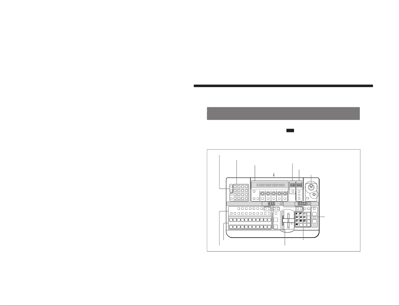
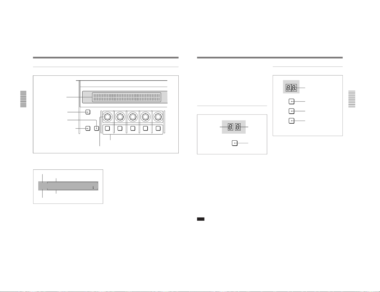
Control Panel
This section describes the control panel, which is
divided into several sections, as shown below. See the
page numbers shown in parenthesis for more details.
Note
If you make an error in operation, a warning sound
may occur. You can switch off this audible warning
(see page 6-10).
1 Delegation section
(see page 2-2)
LAST X
INS
RST
TITLE
12
EDITOR LUM LUM LUM
DSK EDGE
TRAIL
SHADOW
GPI CRK CRK BORDER BEVELD
EDGE
SET UP MASK MASK MASK SOFT
SHIFT CCR LIGHTING BORDERMATTES
LOCATION
LEARNEDIT
RECALL
HOLD
INPUT
INITIAL
PATTERN
ADJ
PAGE
F1 F2 F3 F4 F5
USER PGM
STATUS EDIT
SNAP SHOT
SET
PATTERN NUMBER
EFFECT
DSK
FTB
SET
TRANS RATE
789
456
123
0
DOWN UP
ENTER
FADE
TO
BLACK
P IN P
DSK
DEL
N/R REV DSK PVWDIRECT
RECALL
DIRECT
PATTERN
CCR TITLE 1
SOURCE
TITLE 2
SOURCE
DSK
FILL
SUPER BG FRGD 2 MEMORY FRAME FREEZ MIX EFFECT
BACKGROUND
BLACK MEMORY INT
VIDEO
TITLE
12345678
CUT
AUTO
TRANS
AUXILIARY
BLACK
MEMORY
INT
VIDEO
12345678
FOREGROUND
BLACK
MEMORY
INT
VIDEO
12345678
PATTERN/KEY PAD
2 Primary cross-point bus section
(see page 2-3)
3 Effect transition section
(see page 2-4)
4 Pattern/numeric keypad
(see page 2-5)
5 Fade-to-black
and DSK section
(see page 2-6)
6 EDITOR and GPI buttons
(see page 2-7)
7 Menu control section
(see page 2-7)
8 Effect control section
(see page 2-10)
9 User program section
(see page 2-11)
q; Snapshot section
(see page 2-11)
qa Location section
(see page 2-12)
qs 25-pin
connector
(see
page 2-12)
DFS-700/700P
Page 14
DFS-700/700P
Chapter 2 Location and Function of
Parts and Controls
2-2
Chapter 2 Location and Function of Parts and Controls
1 Delegation section
1 Delegation buttons
CCR TITLE 1
SOURCE
TITLE 2
SOURCE
DSK
FILL
SUPER BG FRGD 2 MEMORY FRAME FREEZ
BLACK MEMORY INT
VIDEO
12345678
AUXILIARY
2 AUXILIARY buttons
3 Frame memory buttons
1 Delegation buttons
Use these buttons to delegate the input signal
corresponding to the selected AUXILIARY button to
the corresponding function. Pressing one of these
buttons lights it, and the corresponding AUXILIARY
button also lights. Any other previously lit delegation
button goes off.
CCR (color corrector) button: Signal for color
correction
TITLE 1 SOURCE button: Title 1 source signal for
inserting characters and graphics using a title key
TITLE 2 SOURCE button: Title 2 source signal for
inserting characters and graphics using a title key
(only available when the optional BKDF-711 2nd
Channel DME Board is installed)
DSK (downstream keyer) FILL button: Fill signal
for the downstream keyer
SUPER BG (background) button: Background
image for 3D effects
FRGD (foreground) 2 button: One of the
foreground images for 3D effects
MEMORY button: Signal captured in frame
memory
2 AUXILIARY buttons
Select the input signal to be assigned to the function
selected with a delegation button.
Select from the following buttons.
BLACK button: Black burst signal generated by the
internal synchronizing signal generator in this unit
Buttons 1 to 8: Signals input to the VIDEO INPUT 1
to 8 connectors on the rear panel of the processor
unit. You can set the assignment of buttons to
input connectors in the setup menu.
MEMORY button: Signal recorded in frame
memory
INT (internal) VIDEO button: Signal generated by
the internal video signal generator
3 Frame memory buttons
FREEZ button: To capture the input signal selected
by the MEMORY button in the delegation buttons
(excluding the frame memory output signal) as a
freeze image in frame memory, press this button,
turning it on.
Press once more to end the freeze, turning it off.
FRAME button: Select whether to capture a frame
or a field with the FREEZ button. Press this
button, turning it on, to freeze a frame; when the
button is off a field is captured.
When capturing fields, you can select in the setup
menu whether to capture an odd or an even field.
Control Panel
Chapter 2 Location and Function of
Parts and Controls
Chapter 2 Location and Function of Parts and Controls
2-3
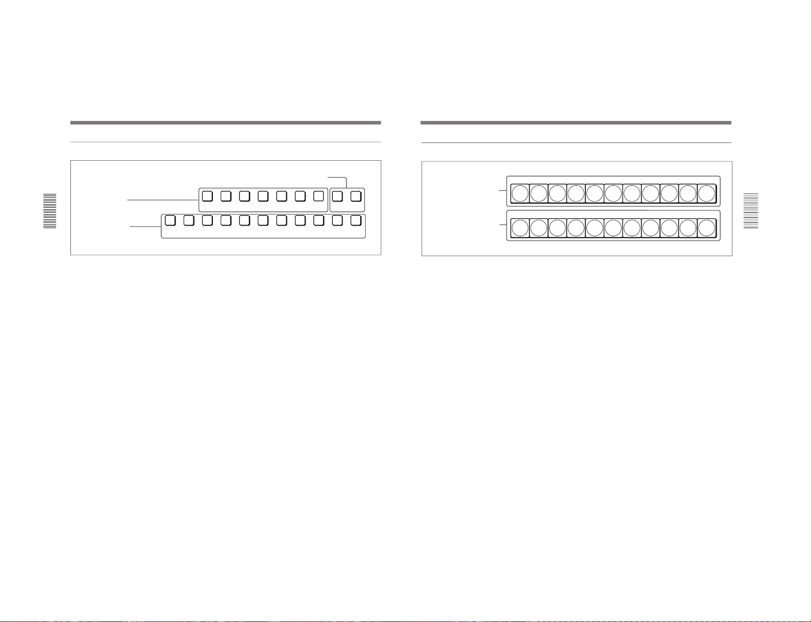
2 Primary cross-point bus section
BACKGROUND
BLACK
MEMORY
INT
VIDEO
12345678
FOREGROUND
BLACK
MEMORY
INT
VIDEO
12345678
2 FOREGROUND bus buttons
1 BACKGROUND bus buttons
1 BACKGROUND bus buttons
Select the image to form the background for an effect.
Select from the following buttons.
BLACK button: Select the black burst signal
generated by the internal synchronizing signal
generator in this unit.
Buttons 1 to 8: Signals input to the VIDEO INPUT 1
to 8 connectors on the rear panel of the processor
unit. Press a button, turning it on, to select the
corresponding signal.
You can set the assignment of buttons to input
connectors in the setup menu.
MEMORY button: Select the signal recorded in
frame memory.
INT (internal) VIDEO button: Select the internal
video signal selected by pressing the MATTES
button in the menu control section. If you hold
down this button and press the DOWN and UP
buttons in the pattern/numeric keypad, the
selected video signal pattern changes.
When the signal on the background bus is output from
the PGM OUT connector on the rear panel of the
processor unit, the button which has been pressed
lights red.
2 FOREGROUND bus buttons
Select the image to form the foreground for an effect
(or the “new” video in a transition).
The functions of the buttons are the same as in the
BACKGROUND bus buttons.
When the signal on the foreground bus is output from
the PGM OUT connector on the rear panel of the
processor unit, the button which has been pressed
lights red. If the signal is not output, the button pressed
lights amber.
1-7
Page 15
1-8
Chapter 2 Location and Function of
Parts and Controls
2-4
Chapter 2 Location and Function of Parts and Controls
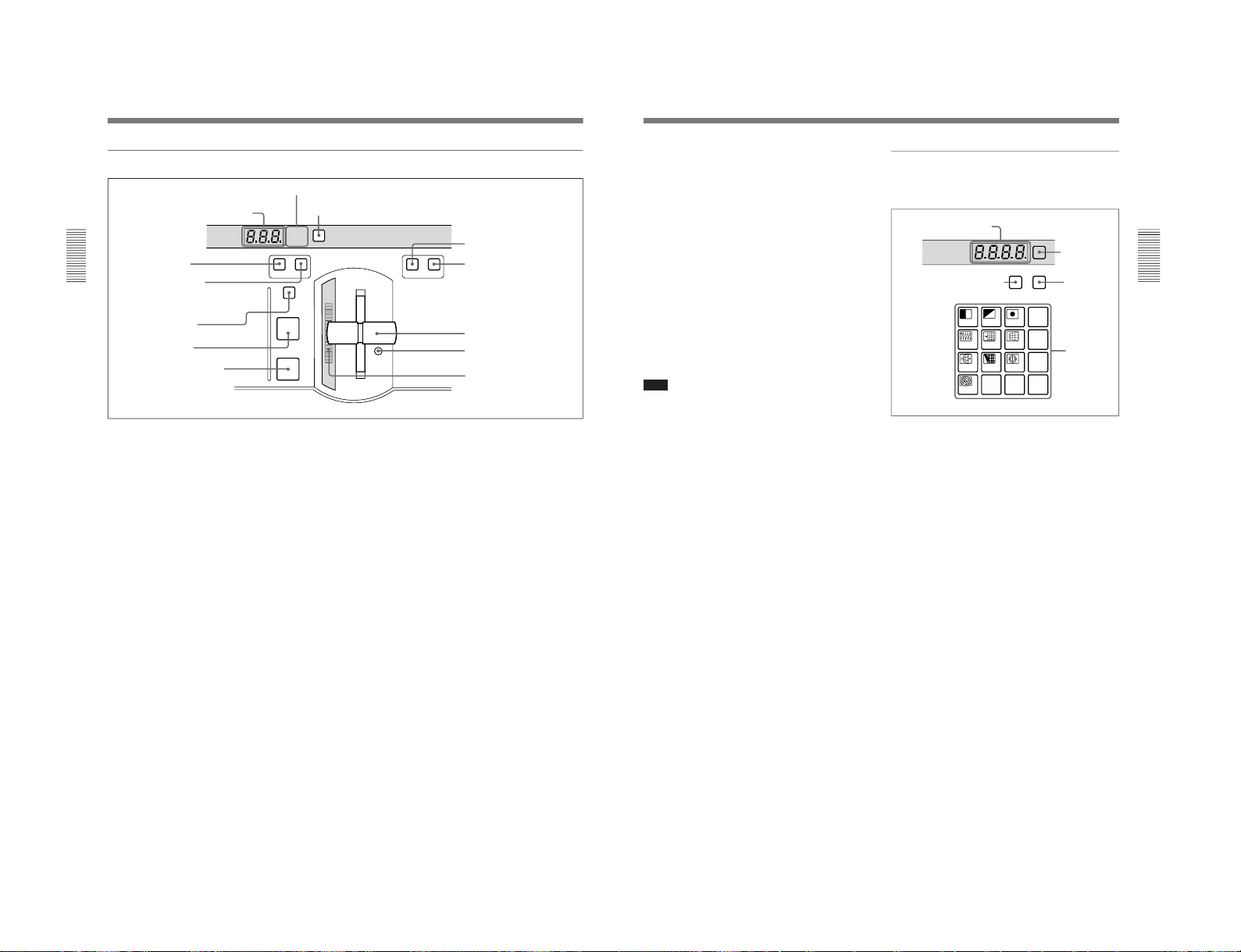
3 Effect transition section
EFFECT
DSK
FTB
SET
TRANS RATE
N/R REV
MIX EFFECT
TITLE
CUT
AUTO
TRANS
2 Display window mode indicators
3 SET button
4 MIX button
7 CUT button
1 TRANS RATE display window
5 EFFECT button
6 TITLE button
8 AUTO TRANS button
9 N/R button
q; REV button
qa Fader lever
qs Fader lever stiffness
adjusting screw
qd Transition indicator
1 TRANS (transition) RATE display window
This shows the transition time for effects, downstream
keys, and fade-to-black, in units of frames. While you
are entering a time, the dot at the lower right of each
numeral lights.
2 Display window mode indicators
These indicate the kind of transition time shown in the
TRANS RATE display window.
EFFECT: Transition time of an effect
DSK: Transition time of a downstream key
FTB: Transition time of a fade-to-black
3 SET button
To set the transition time for an effect, downstream
key, or fade-to-black, press this button, turning it on.
While it is lit, each time you press, the display window
mode indicators change. To set the transition time
corresponding to the display of the display window
mode indicators, enter the value using the pattern/
numeric keypad.
4 MIX button
To carry out the next transition without applying an
effect pattern, but as a mix, press this button, turning it
on.
5 EFFECT button
To carry out the next transition with an effect pattern
applied, press this button, turning it on.
6 TITLE button
To carry out an effect or a mix in title mode, press this
button, turning it on. The title keying is carried out,
inserting the characters and graphics with the effect
pattern and transition settings applied.
7 CUT button
Press this button to carry out an instantaneous
transition.
8 AUTO TRANS (automatic transition) button
Press this button to carry out an effect automatically.
When you press this button, the effect is carried out
automatically, with the transition time which has been
set. During the transition this button is lit. Pressing this
button during the transition pauses it. Press the button
once more to resume the transition.
If you set the fader lever to an intermediate position
and press this button, the transition pauses at the
position corresponding to the fader lever position.
Control Panel
Chapter 2 Location and Function of
Parts and Controls
Chapter 2 Location and Function of Parts and Controls
2-5
9 N/R (normal/reverse) button
To carry out an effect in normal/reverse (i.e.
alternating) mode, press this button, turning it on. It
lights automatically for animation effects and title
keys.
q; REV (reverse) button
To carry out an effect in the reverse direction, press
this button, turning it on.
For an effect for which normal/reverse (alternating)
operation is possible, once the effect is carried out, the
direction is automatically reversed. After an effect is
carried out in the normal (i.e. forward) direction, this
button lights. After an effect is carried out in the
reverse direction, this button goes off.
qa Fader lever
Move this to carry out an effect transition manually.
Note
After powering the system on, move the fader lever to
the end of its travel once in each direction. This
ensures that the fader lever will function correctly.
qs Fader lever stiffness adjusting screw
Turn this screw with a miniature Phillips screwdriver
to adjust the fader lever stiffness. Turn clockwise to
make the fader lever harder to move, and
counterclockwise to make it easier to move.
qd Transition indicator
This indicator consisting of 20 LEDs shows the
progress of an effect transition.
LAST X
INS
RST
SET
PATTERN NUMBER
789
456
123
0
DOWN UP
ENTER
P IN P
DEL
DIRECT
RECALL
DIRECT
PATTERN
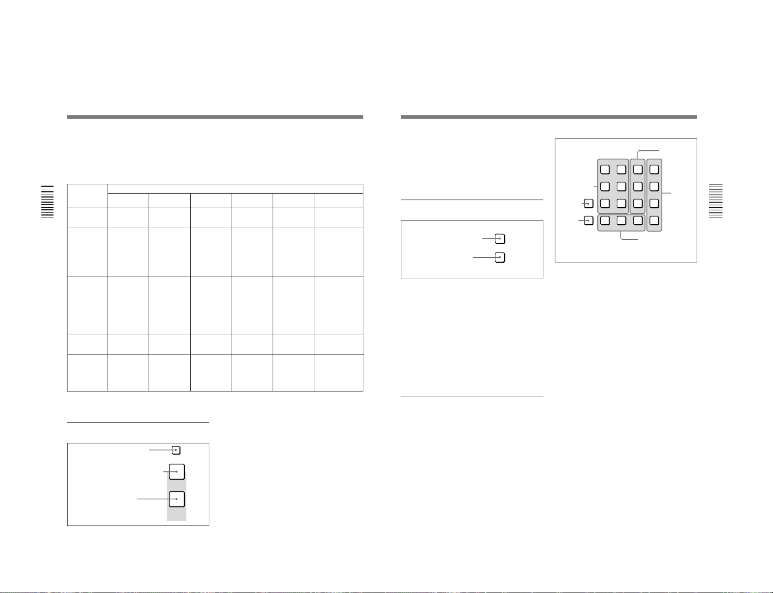
PATTERN/KEY PAD
4 Pattern/numeric keypad
This is used for effect pattern selection, transition time
setting, and other data entry.
1 PATTERN NUMBER display window
This shows an effect pattern number.
While you are entering a pattern number, the dot at the
lower right of each numeral lights.
2 SET button
Press this button, turning it on, to enter the pattern
number specification mode. In this mode, you can use
the PATTERN/KEY PAD buttons to specify an effect
pattern number.
Press this button once more, turning it off, to return to
the direct pattern selection mode.
3 DIRECT RECALL button
Press this button, turning it on, to enter the direct recall
mode. In this mode, pressing one of the PATTERN/
KEY PAD buttons 0 to 9 recalls the corresponding
snapshot 0 to 9.
4 DIRECT PATTERN button
Press this button, turning it on, to enter the direct
pattern selection mode. In this mode, you can use the
PATTERN/KEY PAD buttons (0 to 9 and P IN P/
RST) to directly select the assigned effect patterns.
When the system is powered on, and after exiting any
other operating mode, it automatically switches to
direct pattern selection mode.
1 PATTERN NUMBER
display window
3 DIRECT RECALL button
2 SET
button
4 DIRECT
PATTERN
button
5 PATTERN/
KEY PAD
buttons
DFS-700/700P
Page 16
DFS-700/700P
Chapter 2 Location and Function of
Parts and Controls
2-6
Chapter 2 Location and Function of Parts and Controls
5 PATTERN/KEY PAD buttons
These function as shown in the following table,
according to the selected mode.
Changing labels
You can change the labels on the buttons, using the
supplied labels.
For details of how to change the labels, see page A-63.
Button
Mode
DIRECT
PATTERN
PATTERN
TRANS USER PGM
SNAP SHOT
DIRECT RECALL
0 to 9 Select the
pattern shown
on the button.
a)
Set the pattern
number.
Set the
transition time.
–
Specify a
snapshot
number.
Recall one of
snapshots 0 to 9.
LAST X/INS –
–
– Add a key
frame.
Return to the
state before
recalling a
snapshot.
(Press LAST X
while holding
down the
ENTER button.)
Return to the state
before recalling a
snapshot. (Press
LAST X while
holding down the
ENTER button.)
DEL –
Delete the last
character
entered.
Delete the last
character
entered.
Delete a key
frame.
Delete the last
character
entered.
–
P IN P/RST
Select the
pattern shown
on the button.
a)
Reset the input
value.
Reset the input
value.
Initialize the
parameters.
Reset the input
value.
–
UP Increment the
pattern number.
Increment the
pattern number.
Increment the
transition time
by one frame.
Increment the
key frame
number.
Increment the
snapshot
number.
Increment the
snapshot number.
DOWN Decrement the
pattern number.
Decrement the
pattern number.
Decrement the
transition time
by one frame.
Decrement the
key frame
number.
Decrement the
snapshot
number.
Decrement the
snapshot number.
ENTER – Confirm the
input value.
Confirm the
input value.
Change the key
frame.
Confirm the
input value.
–: Not used
a) For the pattern allocation, see pages 3-18 to 3-20.
5 Fade-to-black and DSK section
FADE
TO
BLACK
DSK
DSK PVW
1 DSK PVW button
2 FADE TO BLACK button
1 DSK PVW (downstream keyer preview) button
When this button is pressed, turning it on, the program
output video is output from the preview output
connectors with the downstream key inserted.
2 FADE TO BLACK button
Press this button, turning it on, to change the entire
program output video to a preset color (factory default:
black). To set the color, press the MATTES button in
the menu control section, and display the setting menu
in the effect control section ((F1) SELECT-FTB).
By pressing the SET button in the effect transition
section, you can set the fade-to-black transition time.
Control Panel
Functions of the PATTERN/KEY PAD buttons
Return to the state
before recalling a
snapshot. (Press
LAST X while
holding down the
ENTER button.)
3 DSK button
Chapter 2 Location and Function of
Parts and Controls
Chapter 2 Location and Function of Parts and Controls
2-7
3 DSK (downstream keyer) button
Press this button, turning it on, to insert the
downstream key set by the DSK section buttons in the
menu control section into the program output video.
By pressing the SET button in the effect transition
section, you can set the downstream key transition
time.
6 EDITOR and GPI buttons
1 EDITOR button
Press this button, turning it on, to accept control from
an external editor connected to the EDITOR connector
on the rear panel of the processor unit.
Press this button once again to turn it off; control is no
longer accepted from the external editor.
2 GPI button
Press this button, turning it on, to accept GPI signals
input to the GPI/T 1 and 2 connectors on the rear panel
of the processor unit.
Press this button once again to turn it off; GPI signals
are no longer accepted.
7 Menu control section
For various effect settings, you press a particular
button in the menu control section, to display a setting
menu in the effect control section. Some buttons toggle
on and off when pressed: in this case the
corresponding effect is disabled when the button is off.
Displaying the menu for a button already lit
Hold down the SHIFT button and press the button
again. This leaves the button lit (and the effect
enabled), while bringing up the menu in the effect
control section. For the LUM and CRK buttons in the
TITLE section, it is not necessary to hold down the
SHIFT button.
EDITOR
GPI
2 GPI button
1 EDITOR button
1 TITLE section
The title key function allows you to superimpose
characters or graphics by cutting out part of the
foreground video with a key source signal, and
applying the effect to the background video.
There are two ways of using the key source signal: as a
luminance key depending only on image intensity, or
as a chroma key, based on a particular color.
Using the buttons in columns 1 and 2 of the TITLE
section, you can insert two title keys (TITLE 2
requires the optional BKDF-711 board to be installed).
To insert a title key, press the TITLE button in the
effect transition section.
The TITLE 1 and TITLE 2 buttons include the
following.
CRK (chroma key) button: Press this to use a
chroma key to cut out the image. When pressed,
this button lights, and portions of the foreground
image of the designated color are cut out as the
key source signal. When this button is lit, the
LUM button is off.
You can carry out chroma keying simply, using
the auto chroma key function.
LUM (luminance) button: Press this to use a
luminance key to cut out the image. When
pressed, this button lights, and portions of the
foreground image are cut out based on the
luminance level. When this button is lit, the CRK
button is off.
TITLE
12
LUM LUM LUM
DSK EDGE
TRAIL
SHADOW
CRK CRK BORDER BEVELD
EDGE
SET UP MASK MASK MASK SOFT
SHIFT CCR LIGHTING BORDERMATTES
2 DSK section
4 CCR, LIGHTING, and
MATTES buttons
1 TITLE section
5 SHIFT
button
6 SET UP
button
3 EDGE
section
1-9
Page 17

1-10
Chapter 2 Location and Function of
Parts and Controls
2-8
Chapter 2 Location and Function of Parts and Controls
MASK button: Press this button to mask off a part
of the key source signal. When you press this
button, it lights, and the system is now in mask
mode, and you can select a rectangular mask in
the effect control section. Normally, the area
outside the mask rectangle is the area which is
masked. To invert the mask, so that the area inside
the rectangle is masked, set INVERT (F5) to ON
in the effect control section.
Press the button once more to turn it off and end
mask mode.
2 DSK (downstream keyer) section
Using a downstream key, you can add characters or
graphics to an image to which an effect has already
been applied. Unlike a title key, you can add this to an
image with a foreground and background
superimposed. To insert a downstream key, press the
DSK button in the fade-to-black and DSK section.
LUM (luminance) button: Press this to display a
menu in the effect control section for adding a key
based on the luminance level of an input signal. In
the effect control section you can select the input
signal to the DSK KEY IN connector on the rear
panel or the input signal selected by the DSK
FILL button in the delegation section as the key
source signal.
BORDER button: Press this button to apply a border
to the characters and graphics inserted as a
downstream key. When you press this button, it
lights, and you can adjust the border settings in the
effect control section.
Press the button once more to turn it off, and
remove the border.
MASK button: Press this button to mask unwanted
parts of the characters and graphics inserted as a
downstream key. When you press this button, it
lights, and the system is now in mask mode, and
you can select a rectangular mask in the effect
control section. Normally, the area outside the
mask rectangle is the area which is masked. To
invert the mask, so that the area inside the
rectangle is masked, set INVERT (F5) to ON in
the effect control section.
Press the button once more to turn it off and end
mask mode.
3 EDGE section
This controls the edge effects applied to the boundary
between the foreground and background images.
TRAIL SHADOW button: Press this button to
apply a trail, drop border, or shadow effect. When
you press this button, it lights, and you can select
and adjust the effect in the effect control section.
•Trail: The foreground pattern leaves a trail of
afterimages.
•Drop border: This applies a border in the
background of the foreground image.
•Shadow: This applies a shadow behind the
foreground image.
Press the button once more to turn it off and
remove the edge effect.
BEVELD (beveled) EDGE button: Press this button
to apply a three-dimensional beveled effect to the
boundary between the foreground and background
images. When you press this button, it lights, and
you can adjust the beveled edge settings in the
effect control section.
Press the button once more to turn it off and
remove the beveled edge effect.
SOFT button: Press this button to soften the
boundary between the foreground and background
images. When you press this button, it lights, and
you can adjust the degree of softness in the effect
control section.
Press the button once more to turn it off and
remove the soft edge effect.
BORDER button: Press this button to apply a border
to the boundary between the foreground and
background images. When you press this button, it
lights, and you can adjust the border settings in the
effect control section.
Press the button once more to turn it off and
remove the border.
Adjusting the cropping: To adjust the cropping, use
the second page (CROP) of the adjustment menu
for beveled edge, soft edge, or border.
Control Panel
Chapter 2 Location and Function of
Parts and Controls
Chapter 2 Location and Function of Parts and Controls
2-9
4 CCR, LIGHTING, and MATTES buttons
CCR (color corrector) button: Press this button to
use the color corrector. When you press this
button, it lights, and you can adjust the color
corrector settings in the effect control section.
Press the button once more to turn it off and exit
the color corrector.
LIGHTING button: Press this button to apply
lighting effects to the foreground image. When
you press this button, it lights, and you can adjust
the lighting settings in the effect control section.
Press the button once more to turn it off and
remove the lighting effect.
MATTES button: By pressing this button, you can
carry out various matte adjustments, matte copies,
and internal video signal selections in the effect
control section.
5 SHIFT button
When a button in the menu control section is lit, but
the corresponding menu is not displayed in the effect
control section, hold down the SHIFT button and press
the lit button. This brings up the menu, without
interrupting the function selection, and leaving the
button lit.
This applies to the following buttons:
•MASK buttons in the TITLE section
•BORDER and MASK buttons in the DSK section
•TRAIL SHADOW, BEVELD EDGE, SOFT, and
BORDER buttons in the EDGE section
•CCR button and LIGHTING button
6 SET UP button
To access the setup menus for system and control
panel settings, press this button. The setup menu
appears in the effect control section.
DFS-700/700P
Page 18
DFS-700/700P
Chapter 2 Location and Function of
Parts and Controls
2-10
Chapter 2 Location and Function of Parts and Controls
8 Effect control section
INITIAL
PATTERN
ADJ
PAGE
F1 F2 F3 F4 F5
2 INITIAL button
3 PAGE button
5 Control knobs
6 F1 to F5 buttons
1 Menu display
4 PATTERN ADJ button
1 Menu display
This shows system and effect settings. Watch this
display while checking and adjusting the settings.
2 INITIAL button
This returns settings to their factory defaults.
•To return a selected setting to its factory default
Hold down the INITIAL button, and press the
corresponding F button (F1 to F5).
•To return all settings on the selected page to their
factory defaults
Hold down the INITIAL button, and press the PAGE
button.
•To return all settings on all pages of the currently
selected menu to their factory defaults (not valid
in setup menu or matte menu)
Hold down the INITIAL button, and press the
PATTERN ADJ button.
INIT SETUP--SNAP--USRPGM--KEYPAD EXEC
6/8 OFF OFF OFF OFF
Menu name or pattern number
Settings
Menu page
Setting values (ON/OFF or parameter values)
3 PAGE button
Press this button to move to the next page of a menu.
Pressing this button on the last page of a menu returns
to the first page.
Holding down the SHIFT button in the menu control
section and pressing this button moves to the previous
menu.
4 PATTERN ADJ (adjust) button
Press this button to adjust the settings for the pattern
number displayed in the PATTERN NUMBER display
window.
This displays the settings for the pattern in the effect
control section.
5 Control knobs
These correspond to the five settings shown in the
menu display. Turn the corresponding knob to adjust a
setting.
6 F1 to F5 buttons
These correspond to the five settings shown in the
menu display.
Press the corresponding button to select a setting, or
toggle it on and off.
Control Panel
Chapter 2 Location and Function of
Parts and Controls
Chapter 2 Location and Function of Parts and Controls
2-11
•Changing a setting value preceded by “+” (setup
menu operations)
Hold down the corresponding F button (F1 to F5),
and turn the control knob.
•Changing a setting value followed by “+” (user
program effect setting operations)
Hold down the corresponding F button (F1 to F5),
and enter the numeric value using the numeric
keypad.
9 User program section
1 STATUS display
When a user program effect is selected, this shows the
number of key frames comprising the effect.
(Maximum 8)
2 EDIT display
In the user program edit mode, this shows the key
frame number to which editing applies.
3 EDIT button
Press this button to edit a user program effect. When
you press this button, it lights, and the system enters
the user program edit mode.
Press the button once more to turn it off and exit the
user program edit mode.
Note
If you press the EDIT button when an effect other than
a user program effect is selected, this does not switch
to user program edit mode.
EDIT
USER
STATUS
EDIT
PGM
1 STATUS display
2 EDIT display
3 EDIT button
q; Snapshot section
1 SNAP SHOT number display
This shows a snapshot number (0 to 99). While you are
entering a number, the dot at the lower right of each
numeral lights.
2 LEARN button
Press this button to save the control panel settings as a
snapshot (learn function).
When you press this button, it lights, and the system
enters learn mode. Enter the snapshot number (0 to 99)
from the numeric keypad, and press the ENTER button
to save the control panel settings in the snapshot.
3 RECALL button
Press this button to recall settings saved as a snapshot.
When you press this button, it lights, and the system
enters recall mode. Enter the snapshot number (0 to
99) from the numeric keypad, and press the ENTER
button to recreate the control panel settings from the
snapshot on the control panel.
LEARN
RECALL
HOLD
INPUT
SNAP SHOT
1 SNAP SHOT number display
2 LEARN button
3 RECALL button
4 HOLD INPUT button
1-11
Page 19
1-12
Chapter 2 Location and Function of
Parts and Controls
2-12
Chapter 2 Location and Function of Parts and Controls
4 HOLD INPUT button
To hold the primary cross-point bus settings and the
auxiliary bus settings (signal selections) fixed when
recalling a snapshot, press this button. When you press
this button, it lights, and when you recall a snapshot,
the system is in the hold input mode. When you recall
a snapshot in this mode, all settings are recreated on
the control panel except those relating to the primary
cross-point bus and the auxiliary bus.
Press the button once more to turn it off and exit the
hold input mode.
qa Location section
1 LOCATION button
Press this button to use the joystick and Z-knob. When
you press this button, it lights, and enables the joystick
and Z-knob.
Press the button once more to disable the joystick and
Z-knob, and return the effect pattern to its default
position.
Holding down the INITIAL button while pressing this
button returns the setting to its default value.
2 Joystick
Use the joystick to position the effect pattern in the xand y-directions.
3 Z-knob
Turn the Z-knob to move an effect pattern in the depth
direction (the z-axis). With this you can change the
effective size of the pattern.
LOCATION
1 LOCATION button
2 Joystick
3 Z-knob
qs 25-pin connector (rear panel)
Use the supplied 25-pin control cable to connect this to
the PANEL connector on the processor unit.
Control Panel
Chapter 2 Location and Function of
Parts and Controls
Chapter 2 Location and Function of Parts and Controls
2-13
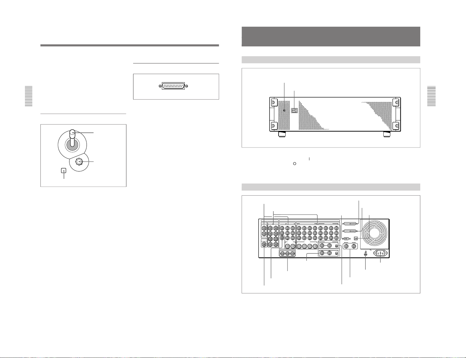
Processor Unit
Front Panel
Power indicator
Power switch
Power switch and indicator
This powers the unit on and off. Press the “
” side of
the switch to power on, and the “
” side to power off.
When the power is on, the power indicator lights
amber.
Rear Panel
1 PGM OUT connectors
1
3
1
2
1
2
2
1
3
4
5
6
7
8
21
Y
COMPOSITE
PGM OUT
CLEAN
OUT
OPTION
SDI INPUT PGM OUT
BLACK BURST OUT
VIDEO INPUT
COMPONENT
S VIDEO
COMPONENT/COMPOSITE
COMPONENT
DIGITAL I/O
ANALOG I/O
AC IN
2
R-Y
PVW
B-Y
65
Y/V
R-Y
B-Y
87
6/2 5/1
Y
R-Y
B-Y
8/4 7/3
2 1
REF.VIDEO IN
GPI/T
PANEL
TALLY
EDITOR
TERMINAL
DSK KEY IN
ON
OFF
OFF
75Ω
ON
75Ω
8
7 6 5
S VIDEO
(OPTION)
(OPTION)
2 1
2 VIDEO INPUT connectors
3 EDITOR
connector
4 PANEL connector
5 TALLY connector
6 TERMINAL connector
7 CLEAN OUT connector
8 PVW connector
9 BLACK BURST OUT 1 to 3
connectors
q; DSK KEY IN connectors
and 75Ω terminator
switch
qa REF. VIDEO IN connectors and 75Ω
terminator switch
qs GPI/T 1 and 2 connectors
qd U terminal
qf - AC IN connector
DFS-700/700P
Page 20

DFS-700/700P
Chapter 2 Location and Function of
Parts and Controls
2-14
Chapter 2 Location and Function of Parts and Controls
1 PGM OUT (program output) connectors
These output the final program output, that is, the
video to which effects have been applied. Connect to
VTR (recorder) and program monitor video input
connectors. The following four types of output are
provided, each with two channels (1 and 2).
SDI (BNC): Output serial digital signals (270 MHz).
COMPOSITE (BNC): Output composite video
signals.
COMPONENT (BNC): Output Betacam format
component video signals (Y, R–Y, B–Y).
S VIDEO (4-pin): Output S-video (Y/C separation)
signals.
You can use all four formats simultaneously. The same
signals are output from connectors 1 and 2.
2 VIDEO INPUT connectors
These input video camera and VTR (player) video
signals. The connectors are in four groups, as follows.
•SDI INPUT 1 to 4, (OPTION) 5 to 8 (BNC)
•COMPONENT 5/1, 6/2, 7/3, 8/4 (BNC)
•COMPONENT/COMPOSITE (OPTION) 5 to 8
(BNC)
•S VIDEO (OPTION) 5 to 8 (4-pin)
SDI INPUT 1 to 4, (OPTION) 5 to 8 (BNC-type)
Input serial digital signals (270 MHz).
Connectors 5 to 8 can only be used when the optional
BKDF-701 SDI and Component Input Board is
installed.
The input signals to these connectors must be
synchronized to this unit.
COMPONENT 5/1, 6/2, 7/3, 8/4 (BNC-type)
Input Betacam format component video signals.
Y: Input the luminance (Y) signal.
R–Y: Input the R–Y color difference signal.
B–Y: Input the B–Y color difference signal.
The input signals to these connectors must be
synchronized to this unit. Therefore, when inputing
from a VTR, the signal must come through a time base
corrector.
The 8/4 column of connectors can be changed to RGB
input connectors by a setup menu operation. In this
case, connect G (with sync), R, and B signals to Y, R–
Y, and B–Y respectively.
When the optional BKDF-702/702P Y/C and
Composite Input Board is installed, you can select in
the setup menu whether to use the 5/1, 6/2, 7/3, and
8/4 connectors for component inputs 5 to 8 or
component inputs 1 to 4.
COMPONENT/COMPOSITE (OPTION) 5 to 8
(BNC-type)
These connectors can be used by installing either of
the optional BKDF-701 and BKDF-702/702P boards.
When the BKDF-701 board is installed, connect
Betacam format component video signals. When the
BKDF-702/702P board is installed, connect composite
video signals. The signals can be input from a VTR
with no time base corrector. When using the BKDF701 to input signals from a VTR, they must come
through a time base corrector.
S VIDEO (OPTION) 5 to 8 (4-pin)
Input S-video (Y/C separation) signals. These
connectors can only be used when the optional BKDF702/702P board is installed. The signals can be input
from a VTR with no time base corrector.
3 EDITOR connector (9-pin)
Use this connector when controlling this unit with an
editor (PVE-500, BVE-2000 series, or other editing
control unit). Using an optional 9-pin remote control
cable, connect to the 9-pin control connector of the
editor.
4 PANEL connector (25-pin)
With the supplied 25-pin control cable, connect to the
25-pin connector of the control panel.
5 TALLY connector (25-pin)
Tally signals are output from this connector when the
signal input to a VIDEO INPUT connector is selected
on the control panel. Connect to the input signal
sources (video cameras etc.). The outputs are relay
contact signals, with a capacity of 200 mA / 30 V.
6 TERMINAL connector (USB type B)
This is a USB interface connector. Use it when
connecting to a computer for a software version
upgrade.
Connector
Input signal for
BKDF-701
Input signal for
BKDF-702/702P
Y/V Luminance (Y) signal
Composite signal
R–Y Color difference
signal (R–Y)
Not used
B–Y Color difference
signal (B–Y)
Not used
Processor Unit
Chapter 2 Location and Function of
Parts and Controls
Chapter 2 Location and Function of Parts and Controls
2-15
7 CLEAN OUT connector (BNC-type)
Outputs serial digital signals (270 MHz). Using the
setup menu, you can select the output from the
following three signals.
CLEAN OUT: The program output signal, without
the downstream key inserted.
PVW OUT: The signal output is the same as the
program output after completion of the effect
transition. The title area can also be shown.
KEY OUT: This outputs a key signal corresponding
to the shape of a selected effect. Use it as the key
source input to another device.
8 PVW (preview) connector (BNC-type)
This is an analog composite preview output. The signal
output is the same as the program output after
completion of the effect transition. It is not possible to
include the title area.
9 BLACK BURST OUT 1 to 3 connectors (BNCtype)
These output the black burst signals generated by the
synchronizing signal generator internal to this unit.
When an external synchronizing signal is input to the
REF. VIDEO IN connectors, the black burst signal
output is locked to the external synchronizing signal.
Use the output from these connectors as a reference
synchronizing signal when synchronizing input signal
sources (character generators, etc.), or when
synchronizing this unit with a VTR or editor to
improve the precision of editing.
q; DSK (downstream keyer) KEY IN connectors
(BNC-type) and 75 Ω terminator switch
Input the key source signal for a downstream key,
from a character generator or other device.
When the 75 Ω terminator switch is in the OFF
position, the connectors provide a loop-through
connection; with the key signal input to one connector,
the other provides the same key source signal to
another device. By connecting to an analog component
Y connector on this unit, you can use it as a title key
source.
When not using the loop-through output, the 75 Ω
terminatior switch must be in the ON position.
qa REF. (reference) VIDEO IN connectors (BNCtype) and 75Ω terminator switch
When using this unit synchronized to an external
signal, input the external reference signal (black burst).
When the 75Ω terminatior switch is in the OFF
position, the connectors provide a loop-through
connection; with the reference signal input to one
connector, the other provides the same reference signal
for another device. When not using the loop-through
output, the 75Ω terminatior switch must be in the ON
position.
qs GPI/T (GPI/trigger) 1 and 2 connectors (BNCtype)
Input external trigger signals. These are used when
controlling editing with GPI signals or an editor (BVE-
600).
qd U (ground) terminal
Connect this to ground as required.
qf - AC IN connector
With the supplied power cord, connect to the AC
supply.
1-13
Page 21

1-14
Chapter 3 Basic Operation
3-1
Chapter
3
Basic Operation
DME Switcher Introduction
This section selects two of the many effects provided by the DFS-700/
700P as examples, and describes the basic flow of operations to use them.
It also describes the demonstration function, which automatically executes
one hundred sample effects.
Sequence of Operations
The flow charts below show the general sequence of operations when
using a DME switcher.
Basic operations (to be
always carried out)
Advanced operations (to be
carried out as required)
Select the background image
(see page 3-13)
Select the foreground image
(see page 3-13)
Inserting characters and graphics (1)
• Luminance key
(see page 3-33)
• Chroma key
(see page 3-36)
Select the effect
(see pages 3-23 and 24)
• Modifying the boundary
(see page 3-26)
• Changing the position and size
(see page
3-29)
• Modifying the pattern
(see page 3-31)
Set up the transition
(see page 3-51)
Reversing the direction of the effect
(see page 3-52)
Execute the effect
(see page 3-54)
Inserting characters and graphics (2)
• Downstream key
(see page 3-45)
DFS-700/700P
Page 22
DFS-700/700P
Chapter 3 Basic Operation
3-2
Chapter 3 Basic Operation
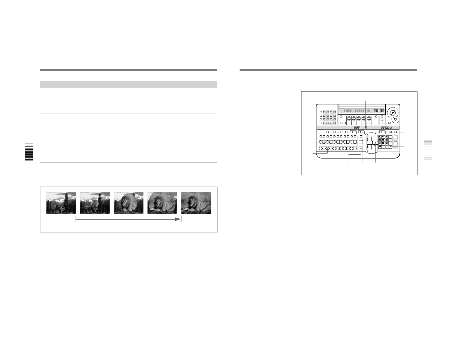
Example Operation (1): Wipe
In this example we’ll use the AUTO TRANS button, to make a wipe, with
the new image appearing from the center of the screen.
Setting items
As an example, we’ll set the control panel as follows.
Background image (the image output before the transition): video
signal connected to the VIDEO INPUT 1 connector
Foreground image (the image output after the transition): video
signal connected to the VIDEO INPUT 2 connector
Effect: wipe (pattern number 24)
Transition time: 30 frames
Program output
Executing the above effect produces the following changes in the output
on a program monitor connected to the PGM OUT connector of the
processor unit.
DME Switcher Introduction
Start of effect
Transition time
End of effect
Chapter 3 Basic Operation
Chapter 3 Basic Operation
3-3
<Preparation>
<Image selection>
Procedure
1
Pull the fader lever toward you as far as it will go.
2
Press BACKGROUND Bus button 1.
The pressed button lights red, and the video signal connected to the
VIDEO INPUT 1 connector is selected as the background image. The
selected background image appears on the program monitor.
3
Press FOREGROUND Bus button 2.
The pressed button lights amber, and the video signal connected to the
VIDEO INPUT 2 connector is selected as the foreground image.
To check the selected image on the program monitor, move the fader
lever to the opposite end. After checking, return the lever to the
position closest to you.
If a preview monitor is connected, the selected foreground image
appears in the preview monitor.
4
Press the DIRECT PATTERN button, turning it on.
(If it is already lit, omit this step.)
The unit is now in direct pattern selection mode. In this mode, you can
select the eleven patterns assigned to buttons in the pattern/numeric
keypad using the corresponding button.
LAST X
INS
RST
TITLE
12
EDITOR LUM LUM LUM
DSK EDGE
TRAIL
SHADOW
GPI CRK CRK BORDER BEVELD
EDGE
SET UP MASK MASK MASK SOFT
SHIFT CCR LIGHTING BORDERMATTES
LOCATION
LEARNEDIT
RECALL
HOLD
INPUT
INITIAL
PATTERN
ADJ
PAGE
F1 F2 F3 F4 F5
USER PGM
STATUS EDIT
SNAP SHOT
SET
PATTERN NUMBER
EFFECT
DSK
FTB
SET
TRANS RATE
789
456
123
0
DOWN UP
ENTER
FADE
TO
BLACK
P IN P
DSK
DEL
N/R REV DSK PVWDIRECT
RECALL
DIRECT
PATTERN
CCR TITLE 1
SOURCE
TITLE 2
SOURCE
DSK
FILL
SUPER BGFRGD 2 MEMORY FRAME FREEZ MIX EFFECT
BACKGROUND
BLACK MEMORY INT
VIDEO
TITLE
12345678
CUT
AUTO
TRANS
AUXILIARY
BLACK
MEMORY
INT
VIDEO
12345678
FOREGROUND
BLACK
MEMORY
INT
VIDEO
12345678
PATTERN/KEY PAD
8
910
3
2
1
6
5,7
4
(Continued)
<Effect selection>
1-15
Page 23
1-16
Chapter 3 Basic Operation
3-4
Chapter 3 Basic Operation
5
Press button 9 in the pattern/numeric keypad.
The button lights, and this selects the wipe assigned to this button
(pattern number 24). The PATTERN NUMBER display window
shows “0024”.
6
Press the SET button once or twice, so that the EFFECT display
window mode indicator lights.
(If it is already lit, omit this step.)
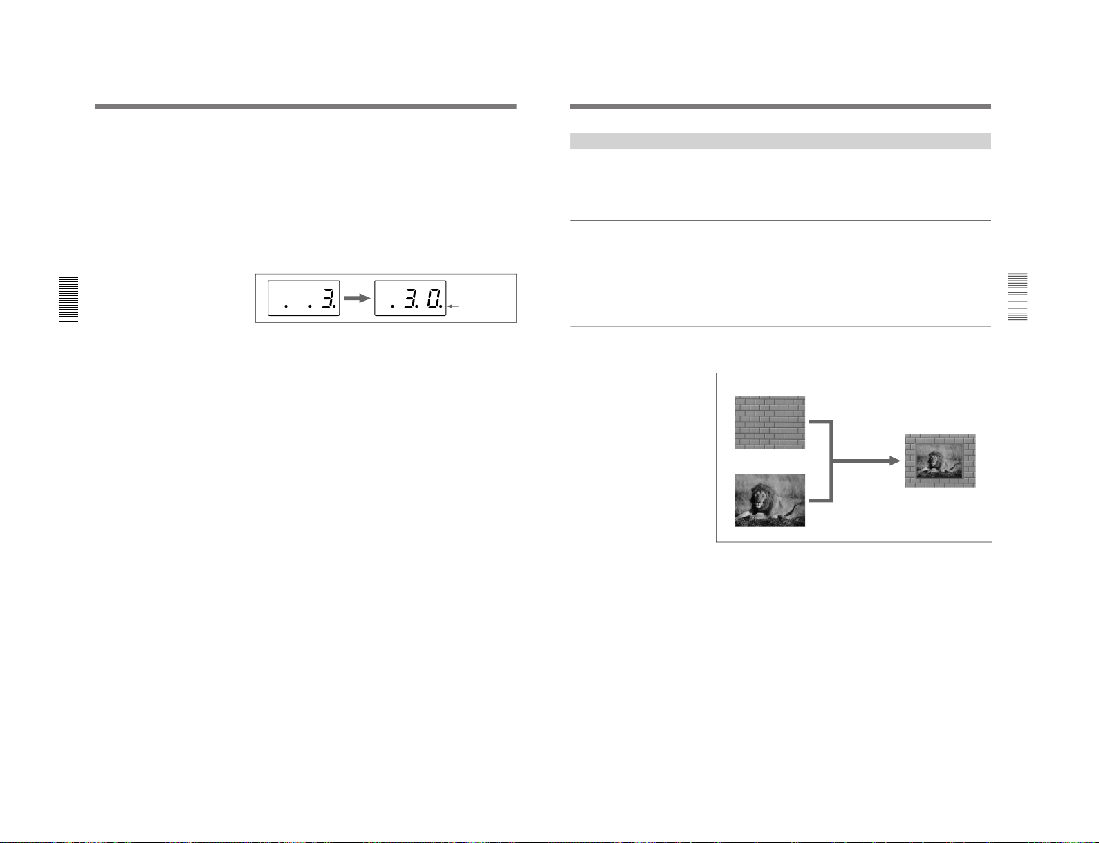
7
In the pattern/numeric keypad, press buttons 3 and 0 in that order.
The TRANS RATE display window shows “.3.0.”.
8
Press the ENTER button.
The dots to the lower right of the digits disappear, and the value
entered in step 7 is set as the transition time.
9
Press the EFFECT button, turning it on.
(If it is already lit, omit this step.)
10
Press the AUTO TRANS button.
The wipe is carried out over 30 frames, switching from the background
image to the foreground image.
When the transition completes, BACKGROUND bus button 2 is lit
red, and FOREGROUND bus button 1 is lit amber. This indicates that
as a result of the transition, the video signal connected to the VIDEO
INPUT 2 connector is automatically selected as the background image,
and the video signal connected to the VIDEO INPUT 1 connector as
the foreground image.
DME Switcher Introduction
<Transition time setting>
Dots appear to
the lower right of
the digits
Chapter 3 Basic Operation
Chapter 3 Basic Operation
3-5
Example Operation (2): Picture-in-Picture
Using the fader lever, we’ll insert the foreground image within the
background image.
We’ll apply a border around the edge of the foreground image.
Setting items
As an example, we’ll set the control panel as follows.
Background image: internal video signal (color background )
Foreground image: video signal connected to the VIDEO INPUT 1
connector
Effect: picture-in-picture (pattern number 1100)
Border: ON
Program output
Executing the above effect produces the following changes in the output
on a program monitor.
Background image
Foreground image
Effect execution
Program output
DFS-700/700P
Page 24
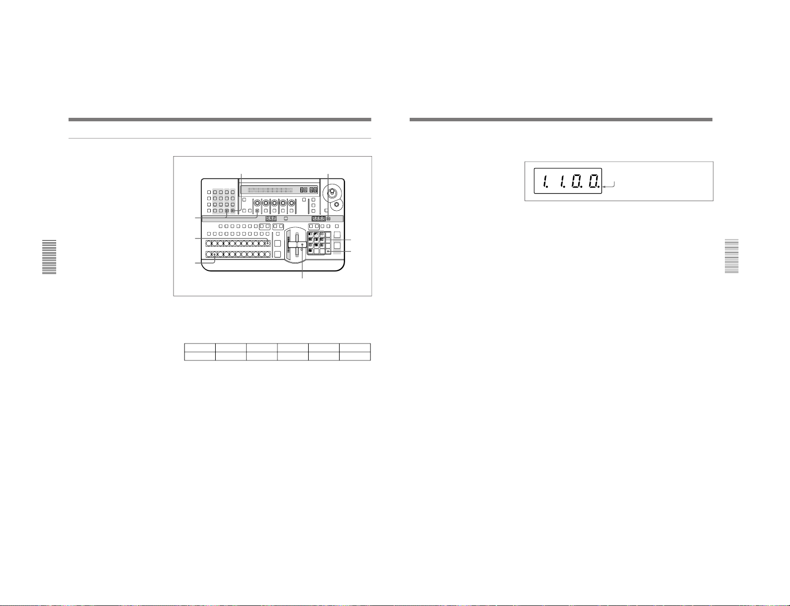
DFS-700/700P
Chapter 3 Basic Operation
3-6
Chapter 3 Basic Operation
Procedure
1
Pull the fader lever toward you as far as it will go.
2
Press the MATTES button in the menu control section, and display
page 1 of the MATTE menu, then with the F1(SELECT) button select
“INT V”.
MATTE
1/2
SELECT
INT V
Lum
0-100
Sat
0-100
Hue
0-99
CH2BRD
BRDMAT
PA GE F1 F2 F3 F4 F5
You can change the color of matte color and embossing pattern. For details,
see the section “Adjusting Color Mattes” (page 3-57).
3
Press the BACKGROUND bus INT VIDEO button.
The pressed button lights red, and a color matte is selected as the
background image.
4
Press the FOREGROUND bus button 1.
The pressed button lights amber, and the video signal connected to the
VIDEO INPUT 1 connector is selected as the foreground image.
5
Press the SET button to the right of the PATTERN NUMBER display
window, turning it on.
(If it is already lit, omit this step.)
LAST X
INS
RST
TITLE
12
EDITOR LUM LUM LUM
DSK EDGE
TRAIL
SHADOW
GPI CRK CRK BORDER BEVELD
EDGE
SET UP MASK MASK MASK SOFT
SHIFT CCR LIGHTING BORDERMATTES
LOCATION
LEARNEDIT
RECALL
HOLD
INPUT
INITIAL
PATTERN
ADJ
PAGE
F1 F2 F3 F4 F5
USER PGM
STATUS EDIT
SNAP SHOT
SET
PATTERN NUMBER
EFFECT
DSK
FTB
SET
TRANS RATE
789
456
123
0
DOWN UP
ENTER
FADE
TO
BLACK
P IN P
DSK
DEL
N/R REV DSK PVWDIRECT
RECALL
DIRECT
PATTERN
CCR TITLE 1
SOURCE
TITLE 2
SOURCE
DSK
FILL
SUPER BGFRGD 2 MEMORY FRAME FREEZ MIX EFFECT
BACKGROUND
BLACK MEMORY INT
VIDEO
TITLE
12345678
CUT
AUTO
TRANS
AUXILIARY
BLACK
MEMORY
INT
VIDEO
12345678
FOREGROUND
BLACK
MEMORY
INT
VIDEO
12345678
PATTERN/KEY PAD
7
4
3
1,9
8
6
2
5
DME Switcher Introduction
<Preparation>
<Image selection>
<Effect selection>
Chapter 3 Basic Operation
Chapter 3 Basic Operation
3-7
<Effect execution>
6
In the numeric keypad, press buttons 1, 1, 0, 0, in that order.
The TRANS RATE display window shows “1.1.0.0.”.
7
Press the ENTER button.
The dots to the lower right of the digits disappear, and picture-inpicture, or pattern number 1100, is selected.
8
In the menu control section, press the BORDER button.
The button lights, enabling the border.
You can change the color and width of the border. For details, see the section
“Modifying the Boundary” (page 3-26).
9
Move the fader lever to the opposite end.
Both the BACKGROUND bus INT VIDEO button and the
FOREGROUND bus button 1 light red.
As you move the lever, the picture-in-picture effect takes place, and a
foreground image with a border is inserted into the background image.
Dots appear to the lower right of the digits.
<Border settings>
1-17
Page 25
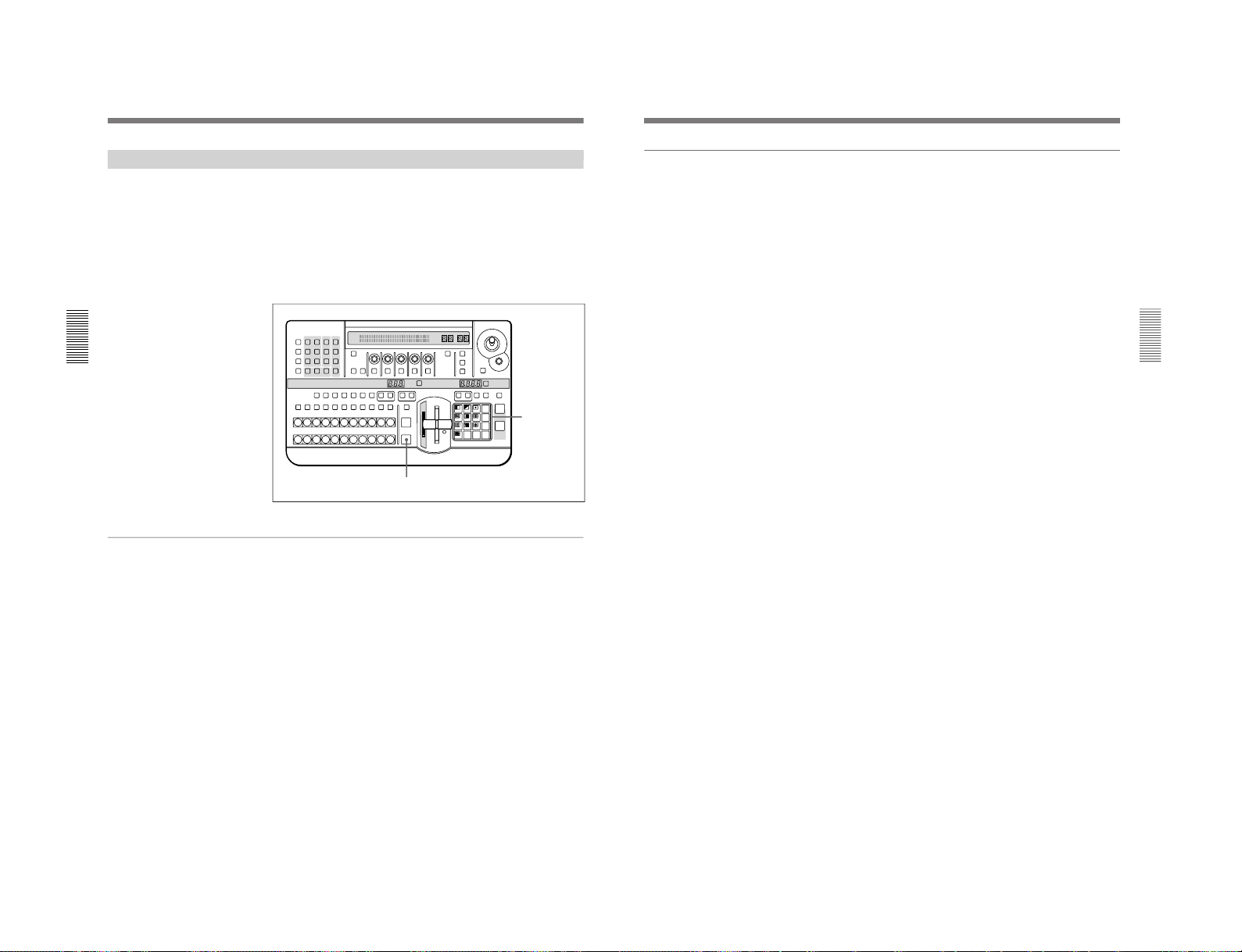
1-18
Chapter 3 Basic Operation
3-8
Chapter 3 Basic Operation
Demonstration
The DFS-700/700P is equipped with a demonstration function, which
automatically plays back one hundred effects stored in ROM in the
processor unit.
The effects (which by factory default are snapshots 0 to 99) have been
chosen to demonstrate the features of the DFS-700/700P as effectively as
possible.
For maximum effect, the demonstration function uses the signals
connected to VIDEO INPUT connectors 1 and 2, and the internal video
signal.
Buttons used for the demonstration
To start the demonstration
In the pattern/numeric keypad, hold down buttons 1 and 9, and press the
AUTO TRANS button.
The one hundred effects stored in ROM are played back continuously, and
repeated until you press the AUTO TRANS button once more. During the
demonstration, the buttons on the pattern/numeric keypad light in turn in
the clockwise direction.
During the demonstration, the control panel does not accept any operations
other than pressing the AUTO TRANS button.
Demonstration with user-registered snapshots
It is also possible to have a demonstration with user-registered snapshots.
In this case, hold down buttons 3 and 7 in the pattern/numeric keypad, and
press the AUTO TRANS button. During the demonstration, the buttons on
the pattern/numeric keypad light in turn in the counterclockwise direction.
LAST X
INS
RST
TITLE
12
EDITOR LUM LUM LUM
DSK EDGE
TRAIL
SHADOW
GPI CRK CRK BORDER BEVELD
EDGE
SET UP MASK MASK MASK SOFT
SHIFT CCR LIGHTING BORDERMATTES
LOCATION
LEARNEDIT
RECALL
HOLD
INPUT
INITIAL
PATTERN
ADJ
PAGE
F1 F2 F3 F4 F5
USER PGM
STATUS EDIT
SNAP SHOT
SET
PATTERN NUMBER
EFFECT
DSK
FTB
SET
TRANS RATE
789
456
123
0
DOWN UP
ENTER
FADE
TO
BLACK
P IN P
DSK
DEL
N/R REV DSK PVWDIRECT
RECALL
DIRECT
PATTERN
CCR TITLE 1
SOURCE
TITLE 2
SOURCE
DSK
FILL
SUPER BGFRGD 2 MEMORY FRAME FREEZ MIX EFFECT
BACKGROUND
BLACK MEMORY INT
VIDEO
TITLE
12345678
CUT
AUTO
TRANS
AUXILIARY
BLACK
MEMORY
INT
VIDEO
12345678
FOREGROUND
BLACK
MEMORY
INT
VIDEO
12345678
PATTERN/KEY PAD
Pattern/numeric
keypad
AUTO TRANS button
DME Switcher Introduction
Chapter 3 Basic Operation
Chapter 3 Basic Operation
3-9
To end the demonstration
Press the AUTO TRANS button once more.
The demonstration ends, and the control panel settings are those of the last
effect in the demonstration.
DFS-700/700P
Page 26
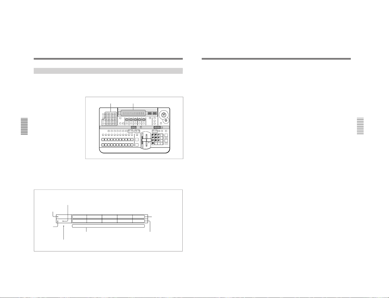
DFS-700/700P
Chapter 3 Basic Operation
3-10
Chapter 3 Basic Operation
Using the Menus
This unit incorporates menus for various effect settings and internal color
matte settings, and also a setup menu for system settings.
This section describes the basic menu operation.
Accessing a menu
Press one of the buttons in the menu control section.
For example, to recall the menu for internal color matte settings, press the
MATTES button in the menu control section. The MATTE menu appears
in the menu display in the effect control section.
In this manual, menus are shown in a tabular format. The following
example shows the MATTE menu.
LAST X
INS
RST
TITLE
12
EDITOR LUM LUM LUM
DSK EDGE
TRAIL
SHADOW
GPI CRK CRK BORDER BEVELD
EDGE
SET UP MASK MASK MASK SOFT
SHIFT CCR LIGHTING BORDERMATTES
LOCATION
LEARNEDIT
RECALL
HOLD
INPUT
INITIAL
PATTERN
ADJ
PAGE
F1 F2 F3 F4 F5
USER PGM
STATUS EDIT
SNAP SHOT
SET
PATTERN NUMBER
EFFECT
DSK
FTB
SET
TRANS RATE
789
456
123
0
DOWN UP
ENTER
FADE
TO
BLACK
P IN P
DSK
DEL
N/R REV DSK PVWDIRECT
RECALL
DIRECT
PATTERN
CCR TITLE 1
SOURCE
TITLE 2
SOURCE
DSK
FILL
SUPER BGFRGD 2 MEMORY FRAME FREEZ MIX EFFECT
BACKGROUND
BLACK MEMORY INT
VIDEO
TITLE
12345678
CUT
AUTO
TRANS
AUXILIARY
BLACK
MEMORY
INT
VIDEO
12345678
FOREGROUND
BLACK
MEMORY
INT
VIDEO
12345678
PATTERN/KEY PAD
Menu control section
Menu page number
“1/2” means that this is the
first of two pages.
Menu name
Refers to the PAGE button.
Refers to buttons and
knobs F1 to F5.
Setting items
(parameters)
Values for the settings
“0-100” indicates a numerical range.
Menu display
MATTE
P 1/2
SELECT
INT V
Lum
0-100
Sat
0-100
Hue
0-99
CH2BRD
BRDMAT
PA GE F1 F2 F3 F4 F5
A “P” appears
here when preread
editing is on.
DME Switcher Introduction
Chapter 3 Basic Operation
Chapter 3 Basic Operation
3-11
Changing settings
•For settings with values shown in letters, press the corresponding one of
buttons F1 to F5.
In the text, this is shown as “the F1(SELECT) button,” with the setting
name after the button name F1 to F5.
•To change a setting with a numerical value, turn the corresponding one of
control knobs F1 to F5.
In the text, this is shown as “the F2(Lum) knob,” with the setting name
after the knob name F1 to F5.
•In the setup menu, when an item has a plus sign in front, hold down the F
button (F4 or F5) and turn the corresponding knob.
For example, in page 3/8 of the setup menu, to change the setting for F4
[+H-pos], hold down the F4 button and turn the F4 knob.
To change the menu page
Press the PAGE button.
Buttons of the menu control section which light when pressed
When you press one of these buttons, it lights, and the settings in the menu
recalled by the button are reflected in the monitor display. To avoid this,
for example just to check the settings in a menu, hold down the SHIFT
button while pressing the menu button.
1-19
Page 27
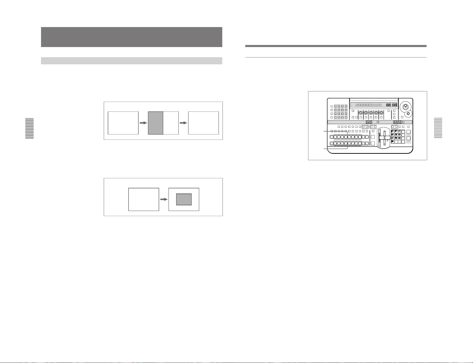
1-20
Chapter 3 Basic Operation
3-12
Chapter 3 Basic Operation
Selecting Images
BF FB
B: background image F: foreground image
B
F
B
B: background image F: foreground image
Background Image and Foreground Image
Background and foreground in a transition effect
In a transition from one image to another, the old image is referred to as
the “background image”. The new image, which replaces the old image, is
referred to as the “foreground image”.
When a transition completes, the background image and foreground image
are interchanged.
Example transition effect: wipe
Background and foreground in an animation effect
In an animation effect, in which an effect pattern is inserted in the image or
moved about on the image, the background image is the background to the
effect, and the inserted effect is referred to as the “foreground image”.
When an animation effect completes, the background image and
foreground image are not interchanged.
Example animation effect: picture-in-picture
Chapter 3 Basic Operation
Chapter 3 Basic Operation
3-13
Selecting the background image and foreground image
As the background image and foreground image you can select any of the
video signals connected to the VIDEO INPUT 1 to 8 connectors of the
processor unit (corresponding to BACKGROUND/FOREGROUND bus
buttons 1 to 8), a freeze frame stored in the frame memory (MEMORY
button), or internal pattern signal (INT VIDEO button).
1
To select the background image, press one of BACKGROUND bus
buttons 1 to 8.
The pressed button lights red.
2
To select the foreground image, press one of FOREGROUND bus
buttons 1 to 8.
The pressed button lights amber.
Program output and lit button colors
The BACKGROUND bus buttons and FOREGROUND bus buttons light
in two colors, depending on whether or not the corresponding image is
present in the current program monitor output (on a video monitor
connected to the PGM OUT connector).
•A button lights red when the image is present in the program monitor
output.
•A button lights amber when the image is not present in the program
monitor output.
LAST X
INS
RST
TITLE
12
EDITOR LUM LUM LUM
DSK EDGE
TRAIL
SHADOW
GPI CRK CRK BORDER BEVELD
EDGE
SET UP MASK MASK MASK SOFT
SHIFT CCR LIGHTING BORDERMATTES
LOCATION
LEARNEDIT
RECALL
HOLD
INPUT
INITIAL
PATTERN
ADJ
PAGE
F1 F2 F3 F4 F5
USER PGM
STATUS EDIT
SNAP SHOT
SET
PATTERN NUMBER
EFFECT
DSK
FTB
SET
TRANS RATE
789
456
123
0
DOWN UP
ENTER
FADE
TO
BLACK
P IN P
DSK
DEL
N/R REV DSK PVWDIRECT
RECALL
DIRECT
PATTERN
CCR TITLE 1
SOURCE
TITLE 2
SOURCE
DSK
FILL
SUPER BGFRGD 2 MEMORY FRAME FREEZ MIX EFFECT
BACKGROUND
BLACK MEMORY INT
VIDEO
TITLE
12345678
CUT
AUTO
TRANS
AUXILIARY
BLACK
MEMORY
INT
VIDEO
12345678
FOREGROUND
BLACK
MEMORY
INT
VIDEO
12345678
PATTERN/KEY PAD
1
2
DFS-700/700P
Page 28
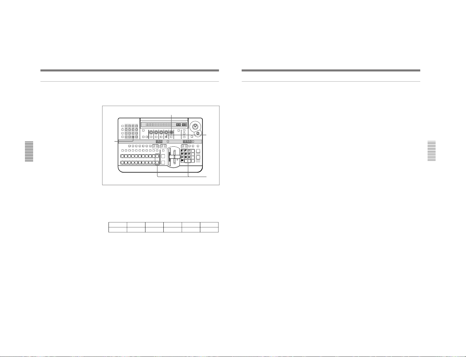
DFS-700/700P
Chapter 3 Basic Operation
3-14
Chapter 3 Basic Operation
Switching the internal video signal selected by the INT VIDEO button
To switch the internal video signal selected by pressing the INT VIDEO
button on either the background bus or foreground bus, use the following
procedure.
1
Press the MATTES button in the menu control section.
Page 1 of the MATTE menu appears.
2
Press the PAGE button in the effect control section, to display page 2
of the MATTE menu, then press the F4(INTVID) button to select the
desired signal.
MATTE
2/2
FROM
INT VTOBORD
COPY
EXEC
INTVID
Matte
PTN
1-80
PA GE F1 F2 F3 F4 F5
You can select any of the following three possibilities.
Matte: color background signal. In the following step 3, you can select
any of plain, or 79 different embossed patterns.
You can adjust the color of the color background signal as desired. For
details, see the section “Adjusting Color Mattes” (page 3-57).
Bar: color bars
Grid: a grid pattern
3
If you have selected a color background signal carry out either of the
following.
•Hold down the INT VIDEO button in the background bus or
foreground bus, and in the pattern/numeric keypad press the UP or
DOWN button.
Each time you press, the pattern changes, and the new pattern appears
on the program monitor.
•Turn the F5(PTN) knob.
LAST X
INS
RST
TITLE
12
EDITOR LUM LUM LUM
DSK EDGE
TRAIL
SHADOW
GPI CRK CRK BORDER BEVELD
EDGE
SET UP MASK MASK MASK SOFT
SHIFT CCR LIGHTING BORDERMATTES
LOCATION
LEARNEDIT
RECALL
HOLD
INPUT
INITIAL
PATTERN
ADJ
PAGE
F1 F2 F3 F4 F5
USER PGM
STATUS EDIT
SNAP SHOT
SET
PATTERN NUMBER
EFFECT
DSK
FTB
SET
TRANS RATE
789
456
123
0
DOWN UP
ENTER
FADE
TO
BLACK
P IN P
DSK
DEL
N/R REV DSK PVWDIRECT
RECALL
DIRECT
PATTERN
CCR TITLE 1
SOURCE
TITLE 2
SOURCE
DSK
FILL
SUPER BGFRGD 2 MEMORY FRAME FREEZ MIX EFFECT
BACKGROUND
BLACK MEMORY INT
VIDEO
TITLE
12345678
CUT
AUTO
TRANS
AUXILIARY
BLACK
MEMORY
INT
VIDEO
12345678
FOREGROUND
BLACK
MEMORY
INT
VIDEO
12345678
PATTERN/KEY PAD
1
3
2
3
Selecting Images
Chapter 3 Basic Operation
Chapter 3 Basic Operation
3-15
Previewing the image after an effect is executed
Select the background image and foreground image, and set up the effect,
then move the fader lever to the opposite end.
You can now check on the program monitor the result of carrying out the
currently set effect.
If a preview monitor is connected, you can check the foreground image on
the preview monitor.
1-21
Page 29
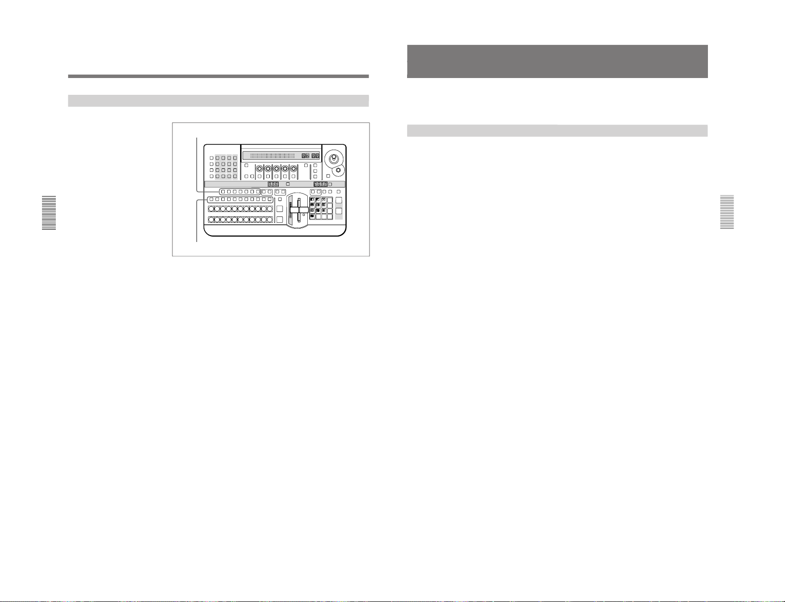
1-22
Chapter 3 Basic Operation
3-16
Chapter 3 Basic Operation
Selecting Signals Output to the Auxiliary Bus
To select the signal to be output to the auxiliary bus, press the desired
AUXILIARY button (BLACK, 1 to 8, MEMORY, or INT VIDEO),
turning it on.
To specify the function for which the selected signal is used, press one of
the delegation buttons, turning it on.
CCR button: use for color correction.
TITLE 1 SOURCE button: use as the key source signal for title key 1.
TITLE 2 SOURCE button: use as the key source signal for title key 2.
DSK FILL button: use as key fill for the downstream keyer.
SUPER BG button: use as background for 3D effects, two-channel
DME effects and so on.
FRGD 2 button: use as the second foreground channel for 3D effects,
two-channel DME effects and so on.
MEMORY button: capture in frame memory.
LAST X
INS
RST
TITLE
12
EDITOR LUM LUM LUM
DSK EDGE
TRAIL
SHADOW
GPI CRK CRK BORDER BEVELD
EDGE
SET UP MASK MASK MASK SOFT
SHIFT CCR LIGHTING BORDERMATTES
LOCATION
LEARNEDIT
RECALL
HOLD
INPUT
INITIAL
PATTERN
ADJ
PAGE
F1 F2 F3 F4 F5
USER PGM
STATUS EDIT
SNAP SHOT
SET
PATTERN NUMBER
EFFECT
DSK
FTB
SET
TRANS RATE
789
456
123
0
DOWN UP
ENTER
FADE
TO
BLACK
P IN P
DSK
DEL
N/R REV DSK PVWDIRECT
RECALL
DIRECT
PATTERN
CCR TITLE 1
SOURCE
TITLE 2
SOURCE
DSK
FILL
SUPER BGFRGD 2 MEMORY FRAME FREEZ MIX EFFECT
BACKGROUND
BLACK MEMORY INT
VIDEO
TITLE
12345678
CUT
AUTO
TRANS
AUXILIARY
BLACK
MEMORY
INT
VIDEO
12345678
FOREGROUND
BLACK
MEMORY
INT
VIDEO
12345678
PATTERN/KEY PAD
Delegation buttons
AUXILIARY buttons
Selecting Images
Chapter 3 Basic Operation
Chapter 3 Basic Operation
3-17
Selecting an Effect
This section describes the types of effects you can use on this system, and
how to select an effect.
Types of Effect
The DFS-700/700P has more than 450 built-in effect patterns provided as
standard.
Each pattern is identified by a number, and the patterns are grouped
together under headings such as “wipe” and “picture-in-picture”.
Transition effects and animation effects
Effects are broadly divided into transition effects and animation effects.
Transition effects: in these effects the background image is completely
replaced by the foreground image. When the effect completes, the
colors in which the BACKGROUND and FOREGROUND bus
buttons are lit become the reverse of those before the effect.
Animation effects: in these effects, for example, the foreground image is
inserted in the background image, and moved around. The foreground
image does not completely replace the background image, and the
colors in which the BACKGROUND and FOREGROUND bus
buttons are lit stay the same.
For the differences between transition and animation effects, see the section
“Background Image and Foreground Image” (page 3-12).
Modifications to effects
Depending on the effect pattern, the following modifications can be added.
•You can add a border to the boundary between the background image and
foreground image, or blur the boundary.
•You can change the pattern position and size.
For details of the modifications that can be applied to the effect patterns, see the
section “Effect Pattern Variant Forms and Decorations” (page A-22).
•You can change a pattern by changing its parameters. (Effects which can
be changed by setting parameters are referred to as “user modifiable
effects”.)
DFS-700/700P
Page 30
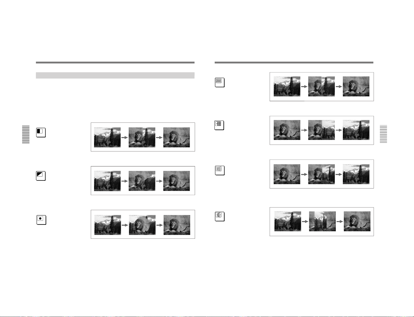
DFS-700/700P
Chapter 3 Basic Operation
3-18
Chapter 3 Basic Operation
Example Effects
This section shows as examples the effect patterns (“direct patterns”)
which you can access simply by pressing a button in the pattern/numeric
keypad. Note that the effect patterns shown below are the factory default
assignments, and you can change the patterns assigned to buttons 0 to 9
and P IN P/RST.
For details of how to change the assignments, see the section “Changing Direct
Pattern Assignments” (page 4-1).
The foreground image appears from the left, and wipes over the
background image to the right.
The foreground image appears from the upper left corner, and wipes over
the background image to the lower right.
The foreground image appears as a circle in the center of the image, and
this circle grows, wiping over the background image.
7
Pattern number: 1
Effect type: wipe
Motion type: transition
8
Pattern number: 9
Effect type: wipe
Motion type: transition
9
Pattern number: 24
Effect type: wipe
Motion type: transition
Selecting an Effect
Chapter 3 Basic Operation
Chapter 3 Basic Operation
3-19
The foreground image appears in the upper left corner, and fills the screen
in a series of vertical strips.
The foreground image appears from the right, and slides over the
background image to the left.
The foreground image appears as a door rotating toward the viewer to
close, and covers the background. When the door is completely closed, the
foreground fills the screen.
The image rotates about a vertical axis as though a panel with the
background on one side. When the panel reaches 90 degrees to the plane of
the screen, the foreground image appears on the other side, and completely
fills the screen when the transition ends.
4
Pattern number: 700
Effect type: matrix wipe
Motion type: transition
5
Pattern number: 1300
Effect type: slide
Motion type: transition
6
Pattern number: 1700
Effect type: 3D rotation
Motion type: transition
1
Pattern number: 1902
Effect type: flip
Motion type: transition
1-23
Page 31

1-24
Chapter 3 Basic Operation
3-20
Chapter 3 Basic Operation
The foreground image appears as though progressively covering the
background image.
The foreground image appears in a ball shape in the upper right. It
“bounces” on the bottom of the screen, then when it reaches the top, turns
into a plane and fills the screen, covering the background image.
The foreground image appears in the center as a rectangle, of the same
aspect ratio as the screen, and grows larger until it covers the background
image.
The foreground image appears as from within the ripples, finally covering
the whole screen with no movement.
2
Pattern number: 2100
Effect type: page turn
Motion type: transition
3
Pattern number: 2200
Effect type: sphere
Motion type: transition
P IN P
RST
Pattern number: 1100
Effect type: picture-in-picture
Motion type: animation
0
Pattern number: 2260
Effect type: ripple
Motion type: transition
Selecting an Effect
Chapter 3 Basic Operation
Chapter 3 Basic Operation
3-21
Nonlinear effects
These effects include effects such as ripples, under names such as lens,
burst, explosion, swirl, and rings.
Two-channel DME effects
These effects combine two foreground images with the background image.
They include two-channel picture-in-picture, two-picture intersect, twopicture brick, two-channel page turn, and so on.
Note
To use two-channel DME effects requires the optional BKDF-711 2nd
Channel DME Board.
Ripple
Lens Swirl
Explosion
Two-channel picture-in-picture
Two-picture Intersect Masked flip
DFS-700/700P
Page 32

DFS-700/700P
Chapter 3 Basic Operation
3-22
Chapter 3 Basic Operation
3D mapping effects
These effects use nonlinear image processing techniques. They include 3D
page turn, 3D beveled edge, and so on.
Note
Using 3D mapping effects requires the optional BKDF-712 3D Video
Mapping Effects Board.
Using the three-picture cube effect also requires the optional BKDF-711
2nd Channel DME Board.
3D wave
3D page turn
3D beveled edge
Selecting an Effect
Three-picture cube
Multi-cube
3D cylinder
Chapter 3 Basic Operation
Chapter 3 Basic Operation
3-23
Selection in Direct Pattern Selection Mode
In the direct pattern selection mode, pressing any button (other than INS,
DEL, UP, DOWN, or ENTER) in the pattern/numeric keypad directly
selects an effect pattern.
For details of the effects assigned by factory default to the buttons in the pattern/
numeric keypad, see the previous section “Example Effects” (page 3-18).
Procedure
To select an effect pattern in the direct pattern selection mode, use the
following procedure.
Note
If the EDIT button in the user program section (see page 2-11) is lit, first
press it, turning it off.
1
Press the DIRECT PATTERN button, turning it on.
The unit is now in direct pattern selection mode.
2
In the pattern/numeric keypad, press the button assigned to the desired
effect pattern, turning it on.
This selects the effect assigned to the button, and the pattern number
appears in the PATTERN NUMBER display window.
LAST X
INS
RST
TITLE
12
EDITOR LUM LUM LUM
DSK EDGE
TRAIL
SHADOW
GPI CRK CRK BORDER BEVELD
EDGE
SET UP MASK MASK MASK SOFT
SHIFT CCR LIGHTING BORDERMATTES
LOCATION
LEARNEDIT
RECALL
HOLD
INPUT
INITIAL
PATTERN
ADJ
PAGE
F1 F2 F3 F4 F5
USER PGM
STATUS EDIT
SNAP SHOT
SET
PATTERN NUMBER
EFFECT
DSK
FTB
SET
TRANS RATE
789
456
123
0
DOWN UP
ENTER
FADE
TO
BLACK
P IN P
DSK
DEL
N/R REV DSK PVWDIRECT
RECALL
DIRECT
PATTERN
CCR TITLE 1
SOURCE
TITLE 2
SOURCE
DSK
FILL
SUPER BGFRGD 2 MEMORY FRAME FREEZ MIX EFFECT
BACKGROUND
BLACK MEMORY INT
VIDEO
TITLE
12345678
CUT
AUTO
TRANS
AUXILIARY
BLACK
MEMORY
INT
VIDEO
12345678
FOREGROUND
BLACK
MEMORY
INT
VIDEO
12345678
PATTERN/KEY PAD
2
1
1-25
Page 33

1-26
Chapter 3 Basic Operation
3-24
Chapter 3 Basic Operation
Selection in Pattern Number Specification Mode
In the pattern number specification mode, you select the desired effect
pattern by entering the number.
Procedure
To select an effect pattern in the pattern number specification mode, use
the following procedure.
Note
If the EDIT button in the user program section (see page 2-11) is lit, first
press it, turning it off.
1
Press the SET button, turning it on.
2
Enter the desired pattern number using buttons 0 to 9 on the pattern/
numeric keypad.
The number you entered appears in the PATTERN NUMBER display
window. Dots appear at the lower right of each digit, indicating that
the entry is not yet confirmed.
3
Press the ENTER button.
The dots to the lower right of the digits in the PATTERN NUMBER
display window disappear, confirming the pattern number.
LAST X
INS
RST
TITLE
12
EDITOR LUM LUM LUM
DSK EDGE
TRAIL
SHADOW
GPI CRK CRK BORDER BEVELD
EDGE
SET UP MASK MASK MASK SOFT
SHIFT CCR LIGHTING BORDERMATTES
LOCATION
LEARNEDIT
RECALL
HOLD
INPUT
INITIAL
PATTERN
ADJ
PAGE
F1 F2 F3 F4 F5
USER PGM
STATUS EDIT
SNAP SHOT
SET
PATTERN NUMBER
EFFECT
DSK
FTB
SET
TRANS RATE
789
456
123
0
DOWN UP
ENTER
FADE
TO
BLACK
P IN P
DSK
DEL
N/R REV DSK PVWDIRECT
RECALL
DIRECT
PATTERN
CCR TITLE 1
SOURCE
TITLE 2
SOURCE
DSK
FILL
SUPER BGFRGD 2 MEMORY FRAME FREEZ MIX EFFECT
BACKGROUND
BLACK MEMORY INT
VIDEO
TITLE
12345678
CUT
AUTO
TRANS
AUXILIARY
BLACK
MEMORY
INT
VIDEO
12345678
FOREGROUND
BLACK
MEMORY
INT
VIDEO
12345678
PATTERN/KEY PAD
2
3
1
Selecting an Effect
Chapter 3 Basic Operation
Chapter 3 Basic Operation
3-25
If you enter a wrong number
Before pressing the ENTER button press the P IN P/RST button to cancel
the wrong number, then enter the correct number.
Note
If you enter an invalid number (a number with no corresponding pattern),
this is automatically corrected to the closest valid number larger than the
number you entered. However, if you enter a number larger than 9309 this
is corrected to pattern number 0001.
Adjusting the number before confirming
To increment the number by one, press the UP button. Hold down the UP
button to increase the number continuously.
To decrement the number by one, press the DOWN button. Hold down the
DOWN button to decrease the number continuously.
DFS-700/700P
Page 34

DFS-700/700P
Chapter 3 Basic Operation
3-26
Chapter 3 Basic Operation
Modifying the Boundary — Border, Soft Edge,
Beveled Edge, and Crop
You can apply a border to the boundary between the foreground image and
background image, or mask unwanted parts of the image.
There are four effects for modifying the boundary, as follows. You can use
all four simultaneously.
Border: apply a border to the image boundary.
Soft edge: blur the image boundary.
Beveled edge: apply a bevel to the image boundary.
Crop: adjust the image boundary position, to eliminate unwanted parts.
(For picture-in-picture and other effects in which a reduced image is
used, reduce noise on the periphery of the image.)
Note
Depending on the effect pattern, you may not be able to apply the above
effects. For details, see the section “Effect Pattern Variant Forms and
Decorations” (page A-22).
Procedure
Controls used in modifying the boundary
To apply a border
Use the following procedure.
1
Press the BORDER button in the EDGE section, turning it on, and
display page 1 of the EDGE menu.
EDGE
1/2
Border
0-100
Soft
0-100
BvlWid
–100-100
BVLTYP
01-20
BvlInt
0-100
PAGE F1 F2 F3 F4 F5
2
Turn the F1(Border) knob, to set the width of the border.
EDGE section
LAST X
INS
RST
TITLE
12
EDITOR LUM LUM LUM
DSK EDGE
TRAIL
SHADOW
GPI CRK CRK BORDER BEVELD
EDGE
SET UP MASK MASK MASK SOFT
SHIFT CCR LIGHTING BORDERMATTES
LOCATION
LEARNEDIT
RECALL
HOLD
INPUT
INITIAL
PATTERN
ADJ
PAGE
F1 F2 F3 F4 F5
USER PGM
STATUS EDIT
SNAP SHOT
SET
PATTERN NUMBER
EFFECT
DSK
FTB
SET
TRANS RATE
789
456
123
0
DOWN UP
ENTER
FADE
TO
BLACK
P IN P
DSK
DEL
N/R REV DSK PVWDIRECT
RECALL
DIRECT
PATTERN
CCR TITLE 1
SOURCE
TITLE 2
SOURCE
DSK
FILL
SUPER BGFRGD 2 MEMORY FRAME FREEZ MIX EFFECT
BACKGROUND
BLACK MEMORY INT
VIDEO
TITLE
12345678
CUT
AUTO
TRANS
AUXILIARY
BLACK
MEMORY
INT
VIDEO
12345678
FOREGROUND
BLACK
MEMORY
INT
VIDEO
12345678
PATTERN/KEY PAD
Effect control section
Chapter 3 Basic Operation
Chapter 3 Basic Operation
3-27
To blur the image boundary
Use the following procedure.
1
Press the SOFT button in the EDGE section, turning it on, and display
page 1 of the EDGE menu.
EDGE
1/2
Border
0-100
Soft
0-100
BvlWid
–100-100
BVLTYP
01-20
BvlInt
0-100
PAGE F1 F2 F3 F4 F5
2
Turn the F2(Soft) knob, to set the degree of boundary blurring.
To apply a beveled edge to the image boundary
Use the following procedure.
1
Press the BEVELD EDGE button in the EDGE section, turning it on,
and display page 1 of the EDGE menu.
EDGE
1/2
Border
0-100
Soft
0-100
BvlWid
–100-100
BVLTYP
01-20
BvlInt
0-100
PAGE F1 F2 F3 F4 F5
2
Turn knobs F3(BvlWid), F4(BVLTYP), and F5(BvlInt) to set the
width, type, and contrast of the beveled edge.
To remove unwanted portions of the image
Use the following procedure.
1
Press any one of the BORDER, SOFT, and BEVELD EDGE buttons,
turning it on, and display page 2 of the EDGE menu. (Press the PAGE
button to change the page.)
EDGE
2/2
CROP
AUTO
Left
–400-400
Right
–400-400
Top
–300-300
Bottom
–300-300
PAGE F1 F2 F3 F4 F5
2
To adjust the image boundary manually, press the F1(CROP) button to
select “MANUAL”.
3
Turn the F2(Left), F3(Right), F4(Top), F5(Bottom) knobs, to adjust the
four sides of the image boundary.
Note
If in step 2 you set F1(CROP) to “AUTO”, the automatic adjustment for
the particular effect pattern is carried out. Selecting “OFF” disables the
cropping.
When effect parameters are already adjusted
When parameters of a border, soft edge, beveled edge, or crop effect are
already adjusted, simply pressing any one of the BORDER, SOFT, and
BEVELD EDGE buttons in the EDGE section to turn it on allows you to
apply the selected effects to the effect pattern.
1-27
Page 35

1-28
Chapter 3 Basic Operation
3-28
Chapter 3 Basic Operation
Indications in the EDGE menu with square brackets [ ]
The parameters in the EDGE menu for functions which are turned off
appear in square brackets [ ].
For example, when the border function is off, when you display the EDGE
menu the setting for Border appears in square brackets.
In this state the knob adjustment is still valid. When you press the
BORDER button, turning the function on, the new setting is reflected
accordingly.
Modifying the Boundary — Border, Soft Edge, Beveled Edge, and Crop
Chapter 3 Basic Operation
Chapter 3 Basic Operation
3-29
Changing the Pattern Position and Size —
Location (X)(Y)(Z)
You can adjust the position and size of an effect pattern when inserting a
foreground image into the background image.
Note
For some effect patterns it is not possible to change their position and size.
If pressing the LOCATION button does not turn it on, it means that one of
those effect patterns is selected.
For details of whether position and size adjustment is possible for an effect, see
the section “Effect Pattern Variant Forms and Decorations” (page A-22).
Procedure
To change the position and size of an effect pattern use the following
procedure.
1
After checking in the section “Effect Pattern Variant Forms and
Decorations” (page A-22), select an effect pattern for which it is
possible to change the position and size.
2
To move the pattern horizontally (x-axis) or vertically (y-axis), move
the joystick in the location section.
LAST X
INS
RST
TITLE
12
EDITOR LUM LUM LUM
DSK EDGE
TRAIL
SHADOW
GPI CRK CRK BORDER BEVELD
EDGE
SET UP MASK MASK MASK SOFT
SHIFT CCR LIGHTING BORDERMATTES
LOCATION
LEARNEDIT
RECALL
HOLD
INPUT
INITIAL
PATTERN
ADJ
PAGE
F1 F2 F3 F4 F5
USER PGM
STATUS EDIT
SNAP SHOT
SET
PATTERN NUMBER
EFFECT
DSK
FTB
SET
TRANS RATE
789
456
123
0
DOWN UP
ENTER
FADE
TO
BLACK
P IN P
DSK
DEL
N/R REV DSK PVWDIRECT
RECALL
DIRECT
PATTERN
CCR TITLE 1
SOURCE
TITLE 2
SOURCE
DSK
FILL
SUPER BGFRGD 2 MEMORY FRAME FREEZ MIX EFFECT
BACKGROUND
BLACK MEMORY INT
VIDEO
TITLE
12345678
CUT
AUTO
TRANS
AUXILIARY
BLACK
MEMORY
INT
VIDEO
12345678
FOREGROUND
BLACK
MEMORY
INT
VIDEO
12345678
PATTERN/KEY PAD
1
2
3
Y-axis (+)
X-axis (–) X-axis (+)
Y-axis (–)
Joystick
(continued)
DFS-700/700P
Page 36

DFS-700/700P
Chapter 3 Basic Operation
3-30
Chapter 3 Basic Operation
3
To move the pattern in the depth direction (z-axis), turn the Z-knob in
the location section.
Z-knob
Changing the Pattern Position and Size — Location (X)(Y)(Z)
Chapter 3 Basic Operation
Chapter 3 Basic Operation
3-31
Modifying the Pattern — User Modifiable Effects
User modifiable effects are those effects for which you can modify the
effect pattern by varying the parameters. The variable parameters vary
from effect to effect.
For the pattern number of user modifiable effects, and the variable parameters,
see the section “Effect Control Parameter List” (page A-5)
Procedure
To modify the effect pattern by varying the parameters, use the following
procedure.
1
After checking in the section “Effect Control Parameter List” (page A-
5), select a user modifiable effect.
The variable parameters of the selected effect appear in the menu
display.
If the selected effect has no variable parameters, the menu display
shows a message “No Adjustable Parameter”.
2
Using knobs and buttons F1 to F5, set the parameters.
LAST X
INS
RST
TITLE
12
EDITOR LUM LUM LUM
DSK EDGE
TRAIL
SHADOW
GPI CRK CRK BORDER BEVELD
EDGE
SET UP MASK MASK MASK SOFT
SHIFT CCR LIGHTING BORDERMATTES
LOCATION
LEARNEDIT
RECALL
HOLD
INPUT
INITIAL
PATTERN
ADJ
PAGE
F1 F2 F3 F4 F5
USER PGM
STATUS EDIT
SNAP SHOT
SET
PATTERN NUMBER
EFFECT
DSK
FTB
SET
TRANS RATE
789
456
123
0
DOWN UP
ENTER
FADE
TO
BLACK
P IN P
DSK
DEL
N/R REV DSK PVWDIRECT
RECALL
DIRECT
PATTERN
CCR TITLE 1
SOURCE
TITLE 2
SOURCE
DSK
FILL
SUPER BGFRGD 2 MEMORY FRAME FREEZ MIX EFFECT
BACKGROUND
BLACK MEMORY INT
VIDEO
TITLE
12345678
CUT
AUTO
TRANS
AUXILIARY
BLACK
MEMORY
INT
VIDEO
12345678
FOREGROUND
BLACK
MEMORY
INT
VIDEO
12345678
PATTERN/KEY PAD
1
2
1-29
Page 37

1-30
Chapter 3 Basic Operation
3-32
Chapter 3 Basic Operation
Example of user modifiable effect parameters
As an example, if you select mosaic (pattern number 1016), the following
parameters appear in the menu display.
1016
1/1
Size
0-100
Aspect
0-100
Soft
0-100
MskAsp
0-100
TYPE
FLAT
PAGE F1 F2 F3 F4 F5
For the effect of the parameters, see the following figure.
Parameters for mosaic (pattern number 1016)
F1(Size): size of a mosaic cell
F2(Aspect): aspect ratio of a mosaic cell
F4(MskAsp): aspect ratio of area to
which mosaic is applied
Modifying the Pattern — User Modifiable Effects
Chapter 3 Basic Operation
Chapter 3 Basic Operation
3-33
Inserting Characters and Graphics (1) — Title Key
You can insert (or superimpose) text and graphics into the background
image while applying effects. You can use either a luminance key or a
chroma key for this insertion.
Luminance Key
In a luminance key, a certain luminance level in the foreground image is
used as the threshold for creating the key signal, and the corresponding
part of the foreground image is inserted into the background image.
Normally the foreground image is on a black background, consisting of
bright text to be inserted in the background image.
Two-channel luminance keying
With the optional 2nd Channel DME Board installed, you can also use a
second luminance key channel.
When using two luminance keys, you must make both title 1 and title 2
settings in the TITLE section of the menu control section. Note that to
select the foreground signal used for the second luminance key, in the
delegation section press the FRGD 2 button, turning it on, then select the
desired video signal with one of the AUXILIARY buttons.
Background image
Foreground image
Composite image formed by
luminance keying (program output)
DFS-700/700P
Page 38

DFS-700/700P
Chapter 3 Basic Operation
3-34
Chapter 3 Basic Operation
Procedure
To insert text and graphics in a background image by means of a
luminance key, use the following procedure.
1
With the BACKGROUND bus buttons, select the background image.
The selected background image appears on the program monitor.
2
With the FOREGROUND bus buttons, select the foreground image.
If a preview monitor is connected, the selected foreground image
appears in the preview monitor.
3
Select the effect pattern, and press the TITLE button in the effect
transition section, turning it on.
Note
Depending on the effect pattern, it may not be possible to use a luminance
key. If such a pattern is selected, the TITLE button does not light. Check
the “TITLE” column of the table in the section “Effect Pattern Variant
Forms and Decorations” (page A-22), and select a pattern for which this
shows a check mark (√).
When the TITLE button lights, the N/R button also automatically lights,
indicating that the system is in N/R (normal/reverse) mode. While the
TITLE button is lit, it is not possible to switch out of N/R mode.
LAST X
INS
RST
TITLE
12
EDITOR LUM LUM LUM
DSK EDGE
TRAIL
SHADOW
GPI CRK CRK BORDER BEVELD
EDGE
SET UP MASK MASK MASK SOFT
SHIFT CCR LIGHTING BORDERMATTES
LOCATION
LEARNEDIT
RECALL
HOLD
INPUT
INITIAL
PATTERN
ADJ
PAGE
F1 F2 F3 F4 F5
USER PGM
STATUS EDIT
SNAP SHOT
SET
PATTERN NUMBER
EFFECT
DSK
FTB
SET
TRANS RATE
789
456
123
0
DOWN UP
ENTER
FADE
TO
BLACK
P IN P
DSK
DEL
N/R REV DSK PVWDIRECT
RECALL
DIRECT
PATTERN
CCR TITLE 1
SOURCE
TITLE 2
SOURCE
DSK
FILL
SUPER BGFRGD 2 MEMORY FRAME FREEZ MIX EFFECT
BACKGROUND
BLACK MEMORY INT
VIDEO
TITLE
12345678
CUT
AUTO
TRANS
AUXILIARY
BLACK
MEMORY
INT
VIDEO
12345678
FOREGROUND
BLACK
MEMORY
INT
VIDEO
12345678
PATTERN/KEY PAD
3
64
1
2
5
Inserting Characters and Graphics (1) — Title Key
Chapter 3 Basic Operation
Chapter 3 Basic Operation
3-35
4
In the TITLE section of the menu control section, press a LUM button,
turning it on.
The luminance key menu appears in the menu display. In the following
example, the LUM button in column 1 is lit.
T1LUM
1/1
Clip
0-100
Gain
0-100
INVERT
OFF
FILL
VIDEO
Densty
0-100
PAGE F1 F2 F3 F4 F5
5
Either press the CUT button in the effect transition section, or move
the fader lever.
A composite of the foreground and background images appears in the
program monitor.
At this point, though, (before adjustment), either of the background
image or foreground image may not be visible.
When the foreground image consists of dark lettering on a
light background
In the luminance key menu, press the F3(INVERT) button, turning it
on, then continue to step 6.
6
Watching the composite image on the program monitor, use the
F1(Clip) knob and F2(Gain) knob to adjust the clip and gain as
necessary.
To switch between the composite image and the background
image
Press the CUT button. This toggles between the composite image and the
background image.
To fill the inserted text or image with a color matte (using a
color matte as key fill)
You can use the same color as a border or the same color as an effect.
•To use the same color as a border, in the luminance key menu, press the
F4(FILL) button to select “BDRMAT”.
•To use the same color as an effect, in the luminance key menu, press the
F4(FILL) button to select “EFFMAT”.
To change the color of color mattes, see the section “Adjusting Color Mattes”
(page 3-57).
To return from a color matte key fill to the foreground image, press the
F4(FILL) button to select “VIDEO”.
Creating a composite image with a semi-transparent
foreground image
Watching the composite image on the program monitor, turn the
F5(Densty) knob, to adjust the transparency of the foreground image.
To remove the luminance key
Press the TITLE button in the effect transition section, turning it off.
1-31
Page 39

1-32
Chapter 3 Basic Operation
3-36
Chapter 3 Basic Operation
Inserting Characters and Graphics (1) — Title Key
Chroma Keying
In chroma keying, a key signal is created based on a specific reference
color in the foreground image, and used to replace the corresponding parts
of the foreground image by the background image. Normally, the
foreground image is created with a plain blue background, which is then
replaced by the background image.
In this system, you can use either of the following methods to carry out
chroma keying.
•Auto chroma keying
You point the cursor at part of the background, thus specifying the keying
color. This is the quick and easy way to make a composite image.
•Manual chroma keying
You specify the keying color by manual adjustment. This allows you
finer control than with auto chroma keying.
By starting with auto chroma keying, then using manual chroma key
adjustments as required, you can get the optimum composite image
efficiently.
Two-channel chroma keying
With the optional BKDF-711 2nd Channel DME Board installed, you can
use a second chroma key channel.
To use two chroma key channels, set both title 1 and title 2 in the TITLE
section of the menu control section. To select the foreground image used
for the second chroma key channel, press the FRGD 2 button in the
delegation section, turning it on, then with one of the AUXILIARY
buttons select the desired video signal.
To use a normal effect for a title key
In this case, use one of the buttons in column 1 of the TITLE section to
recall the title 1 setting menu (T1LUM, T1CRK, or T1MSK), and make
the settings.
Background image
Foreground image
Composite image formed by chroma
keying (program output)
Chapter 3 Basic Operation
Chapter 3 Basic Operation
3-37
Auto chroma keying
To combine the background image and foreground image by auto chroma
keying, use the following procedure.
1
Select the background image with the BACKGROUND bus buttons.
The selected background image appears on the program monitor.
2
Select the foreground image with the FOREGROUND bus buttons.
If a preview monitor is connected, the selected foreground image
appears in the preview monitor.
3
Select the effect pattern, and press the TITLE button in the effect
transition section, turning it on.
Note
Depending on the effect pattern, it may not be possible to use chroma
keying. If such a pattern is selected, the TITLE button does not light.
Check the “TITLE” column of the table in the section “Effect Pattern
Variant Forms and Decorations” (page A-22), and select a pattern for
which this shows a check mark (√).
When the TITLE button lights, the N/R button also automatically lights,
indicating that the system is in N/R (normal/reverse) mode. While the
TITLE button is lit, it is not possible to switch out of N/R mode.
LAST X
INS
RST
TITLE
12
EDITOR LUM LUM LUM
DSK EDGE
TRAIL
SHADOW
GPI CRK CRK BORDER BEVELD
EDGE
SET UP MASK MASK MASK SOFT
SHIFT CCR LIGHTING BORDERMATTES
LOCATION
LEARNEDIT
RECALL
HOLD
INPUT
INITIAL
PATTERN
ADJ
PAGE
F1 F2 F3 F4 F5
USER PGM
STATUS EDIT
SNAP SHOT
SET
PATTERN NUMBER
EFFECT
DSK
FTB
SET
TRANS RATE
789
456
123
0
DOWN UP
ENTER
FADE
TO
BLACK
P IN P
DSK
DEL
N/R REV DSK PVWDIRECT
RECALL
DIRECT
PATTERN
CCR TITLE 1
SOURCE
TITLE 2
SOURCE
DSK
FILL
SUPER BGFRGD 2 MEMORY FRAME FREEZ MIX EFFECT
BACKGROUND
BLACK MEMORY INT
VIDEO
TITLE
12345678
CUT
AUTO
TRANS
AUXILIARY
BLACK
MEMORY
INT
VIDEO
12345678
FOREGROUND
BLACK
MEMORY
INT
VIDEO
12345678
PATTERN/KEY PAD
3
5,7
64
1
2
(continued)
DFS-700/700P
Page 40

DFS-700/700P
Chapter 3 Basic Operation
3-38
Chapter 3 Basic Operation
Inserting Characters and Graphics (1) — Title Key
4
In the TITLE section of the menu control section, press the CRK
button, turning it on.
In the menu display page 1 of the chroma key menu appears. The
following example appears when the CRK button in column 1 is lit.
T1CRK
1/3
Clip
0-100
Gain
0-100
Hue
0-99
Angle
0-100
AUTO
PAGE F1 F2 F3 F4 F5
5
Press the F5(AUTO) button.
In the program monitor screen, the foreground image appears with a
white box cursor.
The menu changes to the auto chroma key menu (T1ACR).
T1ACR
1/1
Pos H
–100-100
Pos V
–100-100
Size
0-100
– – AUTO
CANCEL START
CRK – –
PAGE F1 F2 F3 F4 F5
6
Turn the following knobs to adjust the cursor, to select the background
color which is used as the reference color for chroma keying.
Notes
•You can also adjust the cursor using the joystick and Z-knob in the
LOCATION section.
•If you press a button which is not related to auto chroma key
operations, this automatically ends the auto chroma key mode.
If there are variations in the background color
Make the cursor as large as possible.
7
Press the F5(START) button.
This executes the auto chroma key, and a composite of the background
and foreground images appears in the program monitor.
Cursor
Foreground image
Cursor adjustment Control knob
Move horizontally. F1(Pos H)
Move vertically. F2(Pos V)
Change the size. F3(SIZE)
Chapter 3 Basic Operation
Chapter 3 Basic Operation
3-39
Making fine adjustments to the composite image
Following the manual chroma key procedure (see next page), adjust the
hue, clip, and gain for the specified chroma key color.
You can also adjust the luminance of the part cut out by the chroma key.
To switch between the composite image and the background
image
Press the CUT button. This toggles between the composite image and the
background image.
To fill the inserted text or image with a color matte (using a
color matte as key fill)
You can use the same color as a border or the same color as an effect.
•To use the same color as a border, in the chroma key menu (T1CRK),
press the F4(FILL) button to select “BDRMAT”.
•To use the same color as an effect, in the chroma key menu (T1CRK),
press the F4(FILL) button to select “EFFMAT”.
To change the color of color mattes, see the section “Adjusting Color Mattes”
(page 3-57).
To return from a color matte key fill to the foreground image, in page 2 of
the chroma key menu (T1CRK) press the F4(FILL) button to select
“VIDEO”.
Color matte key fill
Composite image (program output)
1-33
Page 41

1-34
Chapter 3 Basic Operation
3-40
Chapter 3 Basic Operation
Manual chroma key
To combine the background image and foreground image by manual
chroma keying, use the following procedure.
1
Using the same process as in steps 1 to 3 of the procedure for auto
chroma keying (see page 3-37), select the background image,
foreground image, and effect pattern.
2
In the TITLE section of the menu control section, press the CRK
button, turning it on.
In the menu display page 1 of the chroma key menu appears. The
following example appears when the CRK button in column 1 is lit.
T1CRK
1/3
Clip
0-100
Gain
0-100
Hue
0-99
Angle
0-100
AUTO
PAGE F1 F2 F3 F4 F5
3
Press the CUT button in the effect transition section.
A composite of the foreground and background images appears in the
program monitor.
At this point, though, (before adjustment), either of the background
image or foreground image may not be visible.
LAST X
INS
RST
TITLE
12
EDITOR LUM LUM LUM
DSK EDGE
TRAIL
SHADOW
GPI CRK CRK BORDER BEVELD
EDGE
SET UP MASK MASK MASK SOFT
SHIFT CCR LIGHTING BORDERMATTES
LOCATION
LEARNEDIT
RECALL
HOLD
INPUT
INITIAL
PATTERN
ADJ
PAGE
F1 F2 F3 F4 F5
USER PGM
STATUS EDIT
SNAP SHOT
SET
PATTERN NUMBER
EFFECT
DSK
FTB
SET
TRANS RATE
789
456
123
0
DOWN UP
ENTER
FADE
TO
BLACK
P IN P
DSK
DEL
N/R REV DSK PVWDIRECT
RECALL
DIRECT
PATTERN
CCR TITLE 1
SOURCE
TITLE 2
SOURCE
DSK
FILL
SUPER BGFRGD 2 MEMORY FRAME FREEZ MIX EFFECT
BACKGROUND
BLACK MEMORY INT
VIDEO
TITLE
12345678
CUT
AUTO
TRANS
AUXILIARY
BLACK
MEMORY
INT
VIDEO
12345678
FOREGROUND
BLACK
MEMORY
INT
VIDEO
12345678
PATTERN/KEY PAD
2
3
4
Inserting Characters and Graphics (1) — Title Key
Chapter 3 Basic Operation
Chapter 3 Basic Operation
3-41
4
Watching the composite image on the program monitor, in page 1 of
the chroma key menu, adjust the hue, clip, and gain.
When the background part of the foreground image is not
completely replaced by the background image
Adjust the hue with the F3(Hue) knob and the clip with the F1(Clip)
knob.
When the outline of the foreground image is not clear
Adjust the clip with the F1(Clip) knob and the gain with the F2(Gain)
knob.
In combination with a luminance key
1
Press the PAGE button to display page 3 of the chroma key menu, then
press the F1(LUM) button, setting the parameter to “ON”.
T1CRK
3/3
LUM
ON
Clip
0-100
Gain
0-100
INVERT
OFF
PAGE F1 F2 F3 F4
2
Watching the composite image on the program monitor, use the
F2(Clip) knob to adjust the clip, and the F3(Gain) knob to adjust the
gain. To leave dark portions, press the F4(INVERT) button, setting the
parameter to “ON”.
To switch between the composite image and the background
image
Press the CUT button. This toggles between the composite image and the
background image.
To fill the inserted text or image with a color matte (using a
color matte as key fill)
Use the same procedure as for an auto chroma key (see page 3-39).
DFS-700/700P
Page 42

DFS-700/700P
Chapter 3 Basic Operation
3-42
Chapter 3 Basic Operation
Adjusting the hue range for chroma keying (the “angle” setting)
If there are fluctuations in the background color in the foreground image, it
may not be immediately possible to key the background image into the
whole of the desired background. In this case, you can correct this by
increasing the range of hues (the “angle” setting) used for chroma keying.
(This means using a wider-angled sector of the hue circle.)
Angle setting (Example: using a blue background color)
•Increasing the angle increases the range of hues replaced by the
background image, including shades of cyan and magenta.
•Decreasing the angle decreases the range of hues replaced by the
background image, restricting it to closely-matching blues.
Note
If the foreground image includes a color close to the “background” color in
a position not intended to be replaced by the background image, then if
you make the hue range too wide this part will also be filled by the
background image (key fill).
Eliminating bleeding of colors into the edge of the inserted image (color cancel function)
In a chroma key composite image, on the boundary of the inserted image,
the “background” keying color in the foreground image (usually blue)
tends to bleed into the boundary with the background image. In this case,
by replacing the keying color in the composite image by another color (for
example gray), the boundary is made to stand out less. This function is
called “color cancel”.
To use the color cancel function, use the following procedure.
1
In the TITLE section of the menu control section, press the CRK
button, turning it on, and display page 2 of the chroma key menu.
The following example appears when the CRK button in column 1 is
lit.
T1CRK
2/3
COLCANONSat
0-100
Hue
0-99
Densty
0-100
FILL
VIDEO
PAGE F1 F2 F3 F4 F5
2
In the effect transition section, press the TITLE button, turning it on,
then press the CUT button.
A composite of the foreground and background images appears in the
program monitor.
3
Press the F1(COLCAN) button, setting the parameter to “ON”.
Inserting Characters and Graphics (1) — Title Key
Chapter 3 Basic Operation
Chapter 3 Basic Operation
3-43
4
Watching the composite image on the program monitor, turn the
F3(Hue) and F2(Sat) knobs, until the boundary between the
background image and foreground image provides a natural match of
hue and saturation.
Creating a composite image with a semi-transparent foreground image (density function)
You can make the inserted image semi-transparent, and insert it into the
background image.
Use the following procedure.
1
In the TITLE section of the menu control section, press the CRK
button, turning it on, to display page 2 of the chroma key menu.
The following example appears when the CRK button in column 1 is
lit.
T1CRK
2/3
COLCANONSat
0-100
Hue
0-99
Densty
0-100
FILL
VIDEO
PAGE F1 F2 F3 F4 F5
2
Watching the composite image on the program monitor, turn the
F5(Densty) knob, to adjust the transparency of the inserted image.
1-35
Page 43

1-36
Chapter 3 Basic Operation
3-44
Chapter 3 Basic Operation
Masking Part of a Title Key
You can apply a rectangular mask, to eliminate unwanted parts of the key.
The masked part is filled with the background image.
This operation is common to luminance and chroma keys.
1
In the TITLE section of the menu control section, press one of the
MASK buttons, turning it on.
The mask menu appears in the menu display.
The following example appears when the MASK button in column 1 is
lit.
T1MSK
1/1
Left
–400-400
Right
–400-400
Top
–300-300
INVERT
OFF
Bottom
–300-300
PAGE F1 F2 F3 F4 F5
2
Turn the F1(Left), F2(Right), F3(Top), and F4(Bottom) knobs to set
the mask region.
Removing the mask
Press the MASK button lit in step 1, turning it off.
To invert the mask
In the mask menu, press the F5(INVERT) button, setting it to “ON”.
LAST X
INS
RST
TITLE
12
EDITOR LUM LUM LUM
DSK EDGE
TRAIL
SHADOW
GPI CRK CRK BORDER BEVELD
EDGE
SET UP MASK MASK MASK SOFT
SHIFT CCR LIGHTING BORDERMATTES
LOCATION
LEARNEDIT
RECALL
HOLD
INPUT
INITIAL
PATTERN
ADJ
PAGE
F1 F2 F3 F4 F5
USER PGM
STATUS EDIT
SNAP SHOT
SET
PATTERN NUMBER
EFFECT
DSK
FTB
SET
TRANS RATE
789
456
123
0
DOWN UP
ENTER
FADE
TO
BLACK
P IN P
DSK
DEL
N/R REV DSK PVWDIRECT
RECALL
DIRECT
PATTERN
CCR TITLE 1
SOURCE
TITLE 2
SOURCE
DSK
FILL
SUPER BGFRGD 2 MEMORY FRAME FREEZ MIX EFFECT
BACKGROUND
BLACK MEMORY INT
VIDEO
TITLE
12345678
CUT
AUTO
TRANS
AUXILIARY
BLACK
MEMORY
INT
VIDEO
12345678
FOREGROUND
BLACK
MEMORY
INT
VIDEO
12345678
PATTERN/KEY PAD
1
2
Inserting Characters and Graphics (1) — Title Key
Chapter 3 Basic Operation
Chapter 3 Basic Operation
3-45
As its name implies, the downstream key (often abbreviated as DSK) is a
key which is added downstream the title keying stages, to the alreadyformed composite image made up of the background and foreground
images.
Note that if a preview monitor is connected, you can use it to preview the
downstream key on the composite image by pressing the DSK PVW
button in the fade-to-black/downstream key section.
Inserting Characters and Graphics (2) —
Downstream Key
Background image
Foreground image
Program output
Key source signal
DFS-700/700P
Page 44

DFS-700/700P
Chapter 3 Basic Operation
3-46
Chapter 3 Basic Operation
Inserting Characters and Graphics (2) — Downstream Key
Procedure
To insert a downstream key, use the following procedure.
For details of key source and key fill signal connections, see the section “Key
Signal Connections” (page 6-3).
1
First create the image into which the downstream key is to be inserted.
1) Select the background and foreground images.
2) Select the effect, and create the desired composite image.
2
Select the key source signal for the downstream key.
1) In the DSK section of the menu control section, press the LUM
button, turning it on, and display page 2 of the downstream key
(DSK) menu.
DSK
2/2
SOURCE
EXT
PAGE F1
2) Press the F1(Source) button, and select the signal to be used as the
key signal.
EXT: Use the signal input to the DSK KEY IN connector (external
key mode).
SELF: Use the signal specified as “DSK FILL” in the delegation
section (self-keying mode).
LAST X
INS
RST
TITLE
12
EDITOR LUM LUM LUM
DSK EDGE
TRAIL
SHADOW
GPI CRK CRK BORDER BEVELD
EDGE
SET UP MASK MASK MASK SOFT
SHIFT CCR LIGHTING BORDERMATTES
LOCATION
LEARNEDIT
RECALL
HOLD
INPUT
INITIAL
PATTERN
ADJ
PAGE
F1 F2 F3 F4
USER PGM
STATUS EDIT
SNAP SHOT
SET
PATTERN NUMBER
EFFECT
DSK
FTB
SET
TRANS RATE
789
456
123
0
DOWN UP
ENTER
FADE
TO
BLACK
P IN P
DSK
DEL
N/R REV DSK PVWDIRECT
RECALL
DIRECT
PATTERN
CCR TITLE 1
SOURCE
TITLE 2
SOURCE
DSK
FILL
SUPER BGFRGD 2 MEMORY FRAME FREEZ MIX EFFECT
BACKGROUND
BLACK MEMORY INT
VIDEO
TITLE
12345678
CUT
AUTO
TRANS
AUXILIARY
BLACK
MEMORY
INT
VIDEO
12345678
FOREGROUND
BLACK
MEMORY
INT
VIDEO
12345678
PATTERN/KEY PAD
1
5
1
342
Chapter 3 Basic Operation
Chapter 3 Basic Operation
3-47
3
Select the downstream key fill signal.
1) Press the PAGE button, and switch to page 1 of the downstream
key menu.
DSK
1/2
Clip
0-100
Gain
0-100
INVERT
OFF
Densty
0-100
FILL
VIDEO
PAGE F1 F2 F3 F4 F5
2) Press the F4(FILL) button, to select the signal used as the key fill
signal.
VIDEO: Use the signal specified as “DSK FILL” in the delegation
section. When you select this, press the DSK FILL button in the
delegation section, turning it on, then select the desired bus with
the AUXILIARY buttons.
DSKMAT: Use an internal DSK matte signal.
NONE: Do not use a key fill signal (applying the border only).
Note
When you select “NONE”, DSK border automatically goes on. If you
now forcibly turn the DSK border off, the downstream key will not
appear.
4
Set the downstream key transition time (the time taken to insert the
key).
For an instantaneous insert, set the transition time to zero.
For details of the setting, see the section “Setting the Transition Time” (page
3-51).
5
Press the DSK button to insert the downstream key.
When the downstream key has been inserted, the DSK button lights
red.
During the transition, the DSK button lights amber.
Note
Downstream keys are always delayed by 6H.
Deleting the downstream key
When the DSK button is lit red, press it, turning it off.
Adjusting the outline of the downstream key
If the outline of the inserted text or graphics is not sharp, in page 1 of the
downstream key menu, adjust the F1(Clip) and F2(Gain) knobs as follows.
•To adjust the degree to which the key is cut out, turn the F1(Clip) knob
to adjust the clip level.
•To adjust the sharpness of outline of the key, turn the F2(Gain) knob to
adjust the key gain.
1-37
Page 45

1-38
Chapter 3 Basic Operation
3-48
Chapter 3 Basic Operation
To invert the downstream key source signal
Depending on the desired sense of the key source signal (whether the
white or black portions form the key), in page 1 of the downstream key
menu make the following setting.
•For white lettering on a black background, press the F3(INVERT)
button, setting it to “OFF”.
•For black lettering on a white background, press the F3(INVERT)
button, setting it to “ON”.
Applying a border to a downstream key
You can apply a border to the text or graphics inserted as a downstream
key, and adjust the border color.
For details of adjusting the border color, see the section “Adjusting Color
Mattes” (page 3-57).
To apply a border to a downstream key, use the following procedure.
1
In the DSK section of the menu control section, press the BORDER
button, turning it on.
The downstream key border setting menu (DSK)appears.
DSK
1/1
TYPE
Double
PAGE F1
LAST X
INS
RST
TITLE
12
EDITOR LUM LUM LUM
DSK EDGE
TRAIL
SHADOW
GPI CRK CRK BORDER BEVELD
EDGE
SET UP MASK MASK MASK SOFT
SHIFT CCR LIGHTING BORDERMATTES
LOCATION
LEARNEDIT
RECALL
HOLD
INPUT
INITIAL
PATTERN
ADJ
PAGE
F1 F2 F3 F4 F5
USER PGM
STATUS EDIT
SNAP SHOT
SET
PATTERN NUMBER
EFFECT
DSK
FTB
SET
TRANS RATE
789
456
123
0
DOWN UP
ENTER
FADE
TO
BLACK
P IN P
DSK
DEL
N/R REV DSK PVWDIRECT
RECALL
DIRECT
PATTERN
CCR TITLE 1
SOURCE
TITLE 2
SOURCE
DSK
FILL
SUPER BGFRGD 2 MEMORY FRAME FREEZ MIX EFFECT
BACKGROUND
BLACK MEMORY INT
VIDEO
TITLE
12345678
CUT
AUTO
TRANS
AUXILIARY
BLACK
MEMORY
INT
VIDEO
12345678
FOREGROUND
BLACK
MEMORY
INT
VIDEO
12345678
PATTERN/KEY PAD
321
Inserting Characters and Graphics (2) — Downstream Key
Chapter 3 Basic Operation
Chapter 3 Basic Operation
3-49
2
Press the F1(TYPE) button, to select the border type.
Wide: wide border
Narrow: narrow border
Drop: drop border
Double: double border (combination of drop and narrow borders)
If you selected drop border or double border, you can now specify the
border position with the F2 button.
DSK
1/1
TYPE
Double
POS
T+R
PAGE F1 F2
3
If in step 2 you selected drop border or double border, press the
F2(POS) button to specify the border position.
Each time you press the button it cycles to the next in the sequence
“T+L” (top and left)” t “T+R” (top and right)” t “B+R” (bottom
and right) t “B+L” (bottom and left).
To remove the border
In the DSK section of the menu control section, press the BORDER
button, turning it off.
DFS-700/700P
Page 46

DFS-700/700P
Chapter 3 Basic Operation
3-50
Chapter 3 Basic Operation
To mask a part of the downstream key
You can mask out unwanted portions of a downstream key (text or
graphics).
To use the mask function, use the following procedure.
1
In the DSK section of the menu control section, press the MASK
button, turning it on.
The mask menu (DKMSK) appears in the menu display.
DKMSK
1/1
Left
–400-400
Right
–400-400
Top
–300-300
INVERT
OFF
Bottom
–300-300
PAGE F1 F2 F3 F4 F5
2
Turn the F1(Left), F2(Right), F3(Top), and F4(Bottom) knobs to set
the mask region.
Removing the mask
Press the MASK button lit in step 1, turning it off.
To invert the mask
In the mask menu, press the F5(INVERT) button, setting the parameter to
“ON”.
LAST X
INS
RST
TITLE
12
EDITOR LUM LUM LUM
DSK EDGE
TRAIL
SHADOW
GPI CRK CRK BORDER BEVELD
EDGE
SET UP MASK MASK MASK SOFT
SHIFT CCR LIGHTING BORDERMATTES
LOCATION
LEARNEDIT
RECALL
HOLD
INPUT
INITIAL
PATTERN
ADJ
PAGE
F1 F2 F3 F4 F5
USER PGM
STATUS EDIT
SNAP SHOT
SET
PATTERN NUMBER
EFFECT
DSK
FTB
SET
TRANS RATE
789
456
123
0
DOWN UP
ENTER
FADE
TO
BLACK
P IN P
DSK
DEL
N/R REV DSK PVWDIRECT
RECALL
DIRECT
PATTERN
CCR TITLE 1
SOURCE
TITLE 2
SOURCE
DSK
FILL
SUPER BGFRGD 2 MEMORY FRAME FREEZ MIX EFFECT
BACKGROUND
BLACK MEMORY INT
VIDEO
TITLE
12345678
CUT
AUTO
TRANS
AUXILIARY
BLACK
MEMORY
INT
VIDEO
12345678
FOREGROUND
BLACK
MEMORY
INT
VIDEO
12345678
PATTERN/KEY PAD
21
Inserting Characters and Graphics (2) — Downstream Key
Chapter 3 Basic Operation
Chapter 3 Basic Operation
3-51
Setting Up a Transition
This section describes how to set the transition time and transition
direction.
Setting the Transition Time
The transition time measures the duration of an effect in frames (1/30
second (NTSC) or 1/25 second (PAL)), ranging from 0 to 999 frames.
In this system, you can set the transition time for a downstream key or
fade-to-black independently of the transition time for an effect.
Procedure
To set the transition time, use the following procedure.
1
Press the SET button in the effect transition section until the
appropriate display window mode indicator (EFFECT, DSK, or FTB)
is lit.
EFFECT: for setting the effect transition time
DSK: for setting the downstream key transition time
FTB: for setting the fade-to-black transition time
Note
If the EDIT button in the user program section is lit, it is not possible
to set the transition time. Press the EDIT button, turning it off.
2
With buttons 0 to 9 in the pattern/numeric keypad, enter the desired
transition time (0 to 999 frames).
The value entered appears in the TRANS RATE display window, and
dots appear to the lower right of the digits. You can use the UP and
DOWN buttons to adjust the value.
LAST X
INS
RST
TITLE
12
EDITOR LUM LUM LUM
DSK EDGE
TRAIL
SHADOW
GPI CRK CRK BORDER BEVELD
EDGE
SET UP MASK MASK MASK SOFT
SHIFT CCR LIGHTING BORDERMATTES
LOCATION
LEARNEDIT
RECALL
HOLD
INPUT
INITIAL
PATTERN
ADJ
PAGE
F1 F2 F3 F4 F5
USER PGM
STATUS EDIT
SNAP SHOT
SET
PATTERN NUMBER
EFFECT
DSK
FTB
SET
TRANS RATE
789
456
123
0
DOWN UP
ENTER
FADE
TO
BLACK
P IN P
DSK
DEL
N/R REV DSK PVWDIRECT
RECALL
DIRECT
PATTERN
CCR TITLE 1
SOURCE
TITLE 2
SOURCE
DSK
FILL
SUPER BGFRGD 2 MEMORY FRAME FREEZ MIX EFFECT
BACKGROUND
BLACK MEMORY INT
VIDEO
TITLE
12345678
CUT
AUTO
TRANS
AUXILIARY
BLACK
MEMORY
INT
VIDEO
12345678
FOREGROUND
BLACK
MEMORY
INT
VIDEO
12345678
PATTERN/KEY PAD
3
2
1
(continued)
1-39
Page 47

1-40
Chapter 3 Basic Operation
3-52
Chapter 3 Basic Operation
3
Press the ENTER button.
The dots to the lower right of the digits disappear, confirming the
transition time.
If you make a mistake entering the time
Before pressing the ENTER button press the P IN P/RST button to return
the display to the last confirmed value, then enter the correct time.
Setting the Transition Direction
Transition effects are normally executed in the direction in which the
foreground image enters (forwards, or “normal”). To reverse the direction,
before executing the transition, press the REV button in the effect
transition section, turning it on.
Pressing the REV button once more turns it off, and reverts to the normal
direction.
If you have selected an animation effect, the N/R button lights, and the
normal and reverse directions are used alternately. Each time an effect
completes, the REV button goes on or off alternately.
REV button
LAST X
INS
RST
TITLE
12
EDITOR LUM LUM LUM
DSK EDGE
TRAIL
SHADOW
GPI CRK CRK BORDER BEVELD
EDGE
SET UP MASK MASK MASK SOFT
SHIFT CCR LIGHTING BORDERMATTES
LOCATION
LEARNEDIT
RECALL
HOLD
INPUT
INITIAL
PATTERN
ADJ
PAGE
F1 F2 F3 F4 F5
USER PGM
STATUS EDIT
SNAP SHOT
SET
PATTERN NUMBER
EFFECT
DSK
FTB
SET
TRANS RATE
789
456
123
0
DOWN UP
ENTER
FADE
TO
BLACK
P IN P
DSK
DEL
N/R REV DSK PVWDIRECT
RECALL
DIRECT
PATTERN
CCR TITLE 1
SOURCE
TITLE 2
SOURCE
DSK
FILL
SUPER BGFRGD 2 MEMORY FRAME FREEZ MIX EFFECT
BACKGROUND
BLACK MEMORY INT
VIDEO
TITLE
12345678
CUT
AUTO
TRANS
AUXILIARY
BLACK
MEMORY
INT
VIDEO
12345678
FOREGROUND
BLACK
MEMORY
INT
VIDEO
12345678
PATTERN/KEY PAD
N/R button
Setting Up a Transition
Chapter 3 Basic Operation
Chapter 3 Basic Operation
3-53
Operation of transition effects
The following figure illustrates the execution of an example transition
effect. In the figure, “B” is the background image and “F” the foreground
image.
For the direction of operation of other transition effects, see the section “Effect
Motion Types” (page A-21).
Operation of animation effects
The following figure illustrates the execution of an example animation
effect. In the figure, “B” is the background image and “F” the foreground
image.
For the direction of operation of other animation effects, see the section “Effect
Motion Types” (page A-21).
Operation in the normal direction (REV button off)
Pattern number 1630
F
F
BF
BB
BF
F
F
B
B
Operation in the reverse direction (REV button on)
Pattern number 1630
Operation in the normal direction (REV button off)
Pattern number 1100
F
BF
F
B
B
Operation in the reverse direction (REV button on)
Pattern number 1100
F
BF
F
BB
DFS-700/700P
Page 48

DFS-700/700P
Chapter 3 Basic Operation
3-54
Chapter 3 Basic Operation
To execute an effect, after setting the execution direction (normal/reverse),
in the effect transition section press the AUTO TRANS button, or move
the fader lever.
Using the fader lever
By moving the fader lever from one end of its travel to the other at any
desired speed, you can manually control the transition.
The transition indicator on the left of the fader lever lights progressively
corresponding to the status of the transition. When the transition
completes, the transition indicator goes completely off.
For an effect in which the image switches like a cut, the transition occurs
when the fader lever is in the center position.
Note
After powering on the system, move the fader lever once through the
whole of its travel. This will ensure that the fader lever operates correctly.
To pause the transition
Stop moving the fader lever.
To resume the transition
Start moving the fader lever again.
Executing an Effect
LAST X
INS
RST
TITLE
12
EDITOR LUM LUM LUM
DSK EDGE
TRAIL
SHADOW
GPI CRK CRK BORDER BEVELD
EDGE
SET UP MASK MASK MASK SOFT
SHIFT CCR LIGHTING BORDERMATTES
LOCATION
LEARNEDIT
RECALL
HOLD
INPUT
INITIAL
PATTERN
ADJ
PAGE
F1 F2 F3 F4 F5
USER PGM
STATUS EDIT
SNAP SHOT
SET
PATTERN NUMBER
EFFECT
DSK
FTB
SET
TRANS RATE
789
456
123
0
DOWN UP
ENTER
FADE
TO
BLACK
P IN P
DSK
DEL
N/R REV DSK PVWDIRECT
RECALL
DIRECT
PATTERN
CCR TITLE 1
SOURCE
TITLE 2
SOURCE
DSK
FILL
SUPER BGFRGD 2 MEMORY FRAME FREEZ MIX EFFECT
BACKGROUND
BLACK MEMORY INT
VIDEO
TITLE
12345678
CUT
AUTO
TRANS
AUXILIARY
BLACK
MEMORY
INT
VIDEO
12345678
FOREGROUND
BLACK
MEMORY
INT
VIDEO
12345678
PATTERN/KEY PAD
AUTO TRANS button
Fader lever
Chapter 3 Basic Operation
Chapter 3 Basic Operation
3-55
Using the AUTO TRANS button
To execute the effect automatically at the preset transition time, press the
AUTO TRANS button, turning it on.
To pause the transition
During the transition, press the AUTO TRANS button, turning it off.
Note
If the fader lever is in an intermediate position, then the transition pauses
at the corresponding position. To make sure the transition does not pause,
first move the fader lever to either end of its travel.
To resume the transition
Press the AUTO TRANS button again.
Using the fader lever and AUTO TRANS button together
You can use the AUTO TRANS button to complete a transition started and
paused with the fader lever, or in the opposite way, use the fader lever to
complete a transition started and paused with the AUTO TRANS button.
•If you resume a transition partially executed with the fader lever, using
the AUTO TRANS button, then the transition time taken is in proportion
to the setting for the entire transition. For example, if the transition time
is set to 100 frames, and you carry out the equivalent of 25 frames with
the fader lever, then press the AUTO TRANS button, the remainder of
the transition will take 75 frames.
•If you partially execute the transition with the AUTO TRANS button,
then start moving the fader lever, the transition resumes when the fader
lever reaches the corresponding intermediate position.
Note
When you carry out an auto transition by controlling the processor unit
from an external editor through the EDITOR connector, then regardless of
the fader lever position, the transition is executed in its entirety.
1-41
Page 49

1-42
Chapter 3 Basic Operation
3-56
Chapter 3 Basic Operation
Checking the direction and state of progress of the transition
Whether you are carrying out the effect manually or automatically, the
transition indicator on the left of the fader lever (20 LEDs) shows the state
of progress of the transition.
When you start the transition, the indicator lights progressively in the
direction of the transition, and goes off when the transition completes.
If you pause the transition, the indicator remains on in the corresponding
position.
You can always complete a paused transition by moving the fader lever in
the direction of the unlit indicator segments.
Direction of progress of
transition
Direction of moving
fader lever
Transition indicator
Of the 20 LEDs, ten are lit, showing that the
transition is one-half completed.
Executing an Effect
Chapter 3 Basic Operation
Chapter 3 Basic Operation
3-57
Adjusting Color Mattes
You can adjust the color of each color matte individually, and also copy
parameters from other color mattes.
Procedure
To adjust a color matte, use the following procedure.
1
Press the MATTES button in the menu control section, to display page
1 of the MATTE menu.
MATTE
1/2
SELECT
INT V
Lum
0-100
Sat
0-100
CH2BRD
BRDMAT
Hue
0-99
PAGE F1 F2 F3 F4 F5
2
Press the F1(SELECT) button, to select the color matte to adjust.
INT V (internal video): color matte used for foreground and
background images
BORD (border): color matte used to fill the border applied to an
effect pattern, and as key fill for a title key
EFFECT: general-purpose color matte for use in effects
SHADOW: color matte used for shadows around an input image (fill)
DSKFL (DSK fill): color matte used as key fill for a downstream key
DSKBD (DSK border): color matte used for a downstream key border
FTB: color matte used in place of black in the fade-to-black function
3
Turn the F2(Lum), F3(Sat), and F4(Hue) knobs, to adjust the
luminance, saturation, and hue.
Note
If you vary the luminance of a color matte signal with high saturation,
the saturation is automatically adjusted so as not to go outside the
signal specifications.
LAST X
INS
RST
TITLE
12
EDITOR LUM LUM LUM
DSK EDGE
TRAIL
SHADOW
GPI CRK CRK BORDER BEVELD
EDGE
SET UP MASK MASK MASK SOFT
SHIFT CCR LIGHTING BORDERMATTES
LOCATION
LEARNEDIT
RECALL
HOLD
INPUT
INITIAL
PATTERN
ADJ
PAGE
F1 F2 F3 F4 F5
USER PGM
STATUS EDIT
SNAP SHOT
SET
PATTERN NUMBER
EFFECT
DSK
FTB
SET
TRANS RATE
789
456
123
0
DOWN UP
ENTER
FADE
TO
BLACK
P IN P
DSK
DEL
N/R REV DSK PVWDIRECT
RECALL
DIRECT
PATTERN
CCR TITLE 1
SOURCE
TITLE 2
SOURCE
DSK
FILL
SUPER BGFRGD 2 MEMORY FRAME FREEZ MIX EFFECT
BACKGROUND
BLACK MEMORY INT
VIDEO
TITLE
12345678
CUT
AUTO
TRANS
AUXILIARY
BLACK
MEMORY
INT
VIDEO
12345678
FOREGROUND
BLACK
MEMORY
INT
VIDEO
12345678
PATTERN/KEY PAD
123
DFS-700/700P
Page 50

DFS-700/700P
Chapter 3 Basic Operation
3-58
Chapter 3 Basic Operation
To copy a matte color
To copy the color matte parameters from another color matte, use the
following procedure.
1
Press the MATTES button in the menu control section, to display page
2 of the MATTE menu. (Press the PAGE button to change pages.)
MATTE
2/2
FROM
INT VTOBORD
COPY
EXEC
PAGE F1 F2 F3
INTVID
Matte
PTN
1
F4 F5
2
Press the F1(FROM) button, to select the color matte to be copied.
3
Press the F2(TO) button, to select the color matte to which you want to
make the copy.
4
Press the F3(COPY) button, to carry out the copy.
Adjusting Color Mattes
Chapter 3 Basic Operation
Chapter 3 Basic Operation
3-59
The color correction function allows you to adjust the overall color balance
of images, or correct the white balance for different lighting color
temperatures.
You can apply color correction to the signal input to any one of the
primary input connectors (VIDEO INPUT 1 to 8).
Notes
•Color correction settings cannot be saved in a snapshot.
•The color correction function cannot be used for the effect patterns
numbered 2261, 2264, 2267, 2269, and 2279.
Procedure
To adjust the color balance with the color correction function, use the
following procedure.
1
Press the CCR button in the delegation section, turning it on.
2
Press one of the AUXILIARY buttons, turning it on, to select the bus
to which the color adjustment applies.
3
Press the CCR button in the menu control section, turning it on, to
display the color correction menu (CCR).
CCR
1/1
Gain
0-100
Hue
0-99
Offset
0-100
Gamma
0-100
HueRot
0-99
PAGE F1 F2 F3 F4 F5
Adjusting Image Colors — Color Correction
LAST X
INS
RST
TITLE
12
EDITOR LUM LUM LUM
DSK EDGE
TRAIL
SHADOW
GPI CRK CRK BORDER BEVELD
EDGE
SET UP MASK MASK MASK SOFT
SHIFT CCR LIGHTING BORDERMATTES
LOCATION
LEARNEDIT
RECALL
HOLD
INPUT
INITIAL
PATTERN
ADJ
PAGE
F1 F2 F3 F4 F5
USER PGM
STATUS EDIT
SNAP SHOT
SET
PATTERN NUMBER
EFFECT
DSK
FTB
SET
TRANS RATE
789
456
123
0
DOWN UP
ENTER
FADE
TO
BLACK
P IN P
DSK
DEL
N/R REV DSK PVWDIRECT
RECALL
DIRECT
PATTERN
CCR TITLE 1
SOURCE
TITLE 2
SOURCE
DSK
FILL
SUPER BGFRGD 2 MEMORY FRAME FREEZ MIX EFFECT
BACKGROUND
BLACK MEMORY INT
VIDEO
TITLE
12345678
CUT
AUTO
TRANS
AUXILIARY
BLACK
MEMORY
INT
VIDEO
12345678
FOREGROUND
BLACK
MEMORY
INT
VIDEO
12345678
PATTERN/KEY PAD
3
2
1
4
(continued)
1-43
Page 51

1-44
Chapter 3 Basic Operation
3-60
Chapter 3 Basic Operation
4
Watching the image on the monitor, turn the F1 to F5 knobs to adjust
the color.
F1(Gain): adjust the chrominance gain (the depth of the colors).
F2(Hue): adjust the hue.
Note
When F3(Offset) is set to its minimum value of zero, turning the
F2(Hue) knob has no effect on the hue.
F3(Offset): vary the adjustment range of the F2(Hue) knob.
The larger the value of “Offset,” the wider the range of color
adjustment. A smaller value for “Offset” means that the F2(Hue)
knob can be used for fine adjustment.
F4(HueRot): set the hue.
F5(Gamma): adjust the gamma value of the luminance signal.
To turn off the color correction function
In the menu control section press the CCR button, turning it off.
Adjusting Image Colors — Color Correction
Chapter 3 Basic Operation
Chapter 3 Basic Operation
3-61
Using the frame memory function, you can capture a “freeze frame” from
input video or store a still frame. You can then use this still image as a
video source.
Procedure
To capture a freeze frame in memory, use the following procedure.
1
If the FREEZ button is lit, press it, turning it off.
2
In the delegation section press the MEMORY button, turning it on.
3
Press one of the AUXILIARY buttons, turning it on, to select the input
video signal.
4
Press the MEMORY button in the BACKGROUND bus button row,
turning it on.
5
• To capture a frame from still video, press the FRAME button turning
it on.
• To capture a field from moving video, leave the FRAME button off.
(Pressing the FRAME button toggles it on and off.)
6
Press the FREEZ button, turning it on, to capture the image. (For
capture from a moving video input, press the FREEZ button at the
point you want to capture.)
The captured image appears on the output bus, and is written to
memory.
Note
Even if other than MEMORY is selected on the BACKGROUND bus
buttons, you can still capture the selected image with an AUXILIARY
button.
Freezing an Input Image — Frame Memory
Function
LAST X
INS
RST
TITLE
12
EDITOR LUM LUM LUM
DSK EDGE
TRAIL
SHADOW
GPI CRK CRK BORDER BEVELD
EDGE
SET UP MASK MASK MASK SOFT
SHIFT CCR LIGHTING BORDERMATTES
LOCATION
LEARNEDIT
RECALL
HOLD
INPUT
INITIAL
PATTERN
ADJ
PAGE
F1 F2 F3 F4 F5
USER PGM
STATUS EDIT
SNAP SHOT
SET
PATTERN NUMBER
EFFECT
DSK
FTB
SET
TRANS RATE
789
456
123
0
DOWN UP
ENTER
FADE
TO
BLACK
P IN P
DSK
DEL
N/R REV DSK PVWDIRECT
RECALL
DIRECT
PATTERN
CCR TITLE 1
SOURCE
TITLE 2
SOURCE
DSK
FILL
SUPER BGFRGD 2 MEMORY FRAME FREEZ MIX EFFECT
BACKGROUND
BLACK MEMORY INT
VIDEO
TITLE
12345678
CUT
AUTO
TRANS
AUXILIARY
BLACK
MEMORY
INT
VIDEO
12345678
FOREGROUND
BLACK
MEMORY
INT
VIDEO
12345678
PATTERN/KEY PAD
2
3
4
5 1,6
DFS-700/700P
Page 52

DFS-700/700P
Chapter 3 Basic Operation
3-62
Chapter 3 Basic Operation
Recalling a freeze frame saved in memory
In the BACKGROUND or FOREGROUND bus button row, press
MEMORY, turning it on.
Note
When the unit is powered off, the saved frame is lost from memory.
Freezing an Input Image — Frame Memory Function
Chapter 3 Basic Operation
Chapter 3 Basic Operation
3-63
Fade-to-Black
The fade-to-black allows you to gradually fade the image on the preview
monitor (the background image) until it is completely black.
To carry out a fade-to-black
Press the FADE TO BLACK button in the fade-to-black/downstream key
section.
During the transition, the FADE TO BLACK button lights amber, and
when the transition completes (when the image is completely black), lights
red.
To end a fade-to-black
When the FADE TO BLACK button is lit red (the screen is black), press
the FADE TO BLACK button. The output gradually changes from black to
the image selected on the BACKGROUND bus buttons.
To reverse the direction of a fade-to-black transition during
execution
During the transition (while the FADE TO BLACK button is lit amber),
press the FADE TO BLACK button.
This immediately reverses the direction of the transition.
Setting the fade-to-black transition time
Follow the procedure in the section “Setting the Transition Time” (page 3-
51).
To change the color from black
Follow the procedure in the section “Adjusting Color Mattes” (page 3-57).
To prohibit a fade-to-black
See F4 in the section “Control Panel Setup (page 5/8)” (page 6-10).
LAST X
INS
RST
TITLE
12
EDITOR LUM LUM LUM
DSK EDGE
TRAIL
SHADOW
GPI CRK CRK BORDER BEVELD
EDGE
SET UP MASK MASK MASK SOFT
SHIFT CCR LIGHTING BORDERMATTES
LOCATION
LEARNEDIT
RECALL
HOLD
INPUT
INITIAL
PATTERN
ADJ
PAGE
F1 F2 F3 F4 F5
USER PGM
STATUS EDIT
SNAP SHOT
SET
PATTERN NUMBER
EFFECT
DSK
FTB
SET
TRANS RATE
789
456
123
0
DOWN UP
ENTER
FADE
TO
BLACK
P IN P
DSK
DEL
N/R REV DSK PVWDIRECT
RECALL
DIRECT
PATTERN
CCR TITLE 1
SOURCE
TITLE 2
SOURCE
DSK
FILL
SUPER BGFRGD 2 MEMORY FRAME FREEZ MIX EFFECT
BACKGROUND
BLACK MEMORY INT
VIDEO
TITLE
12345678
CUT
AUTO
TRANS
AUXILIARY
BLACK
MEMORY
INT
VIDEO
12345678
FOREGROUND
BLACK
MEMORY
INT
VIDEO
12345678
PATTERN/KEY PAD
FADE TO BLACK button
1-45
Page 53

1-46
Chapter 4 Advanced Operations
4-1
Chapter
4
Adv anced Operations
Changing Direct Pattern Assignments
You can change the effect patterns assigned to the buttons 0 to 9 and
P IN P/RST. Doing so allows you to select frequently used patterns simply
by pressing the corresponding buttons in direct pattern selection mode.
To change the direct pattern assignment
To change the direct pattern assignment to the buttons 0 to 9 and P IN P/
RST, use the following procedure.
1
Press the SET button.
The button lights, and the unit enters pattern number entry mode.
LAST X
INS
RST
TITLE
12
EDITOR LUM LUM LUM
DSK EDGE
TRAIL
SHADOW
GPI CRK CRK BORDER BEVELD
EDGE
SET UP MASK MASK MASK SOFT
SHIFT CCR LIGHTING BORDERMATTES
LOCATION
LEARNEDIT
RECALL
HOLD
INPUT
INITIAL
PATTERN
ADJ
PAGE
F1 F2 F3 F4 F5
USER PGM
STATUS EDIT
SNAP SHOT
SET
PATTERN NUMBER
EFFECT
DSK
FTB
SET
TRANS RATE
789
456
123
0
DOWN UP
ENTER
FADE
TO
BLACK
P IN P
DSK
DEL
N/R REV DSK PVWDIRECT
RECALL
DIRECT
PATTERN
CCR TITLE 1
SOURCE
TITLE 2
SOURCE
DSK
FILL
SUPER BGFRGD 2 MEMORY FRAME FREEZ MIX EFFECT
BACKGROUND
BLACK MEMORY INT
VIDEO
TITLE
12345678
CUT
AUTO
TRANS
AUXILIARY
BLACK
MEMORY
INT
VIDEO
12345678
FOREGROUND
BLACK
MEMORY
INT
VIDEO
12345678
PATTERN/KEY PAD
4
2,4
4
1
3
PATTERN NUMBER display window
(continued)
DFS-700/700P
Page 54

DFS-700/700P
Chapter 4 Advanced Operations
4-2
Chapter 4 Advanced Operations
2
Use buttons 0 to 9 to enter the pattern number you want to assign to a
button.
For more information about pattern numbers, see the section “Effect Pattern
Image List” (page A-29).
The number you enter appears in the PATTERN NUMBER display
window.
3
Press the ENTER button.
4
While holding down the DIRECT PATTERN button, press the button
(0 to 9, or P IN P/RST) to which you want to assign the pattern.
The button you pressed lights, and the pattern number entered in step 2
is assigned to the button.
To restore the default assignments (direct pattern reinitialization)
After changing pattern assignments, you can restore the factory default
assignments shown in “Example Effects” (page 3-18).
To return all of the buttons 0 to 9 and P IN P/RST to their factory default
assignments, use the following procedure.
1
Press the SET UP button.
The setup menu appears.
2
Press the PAGE button to display page 6/8.
3
Press the F4(KEYPAD) button to set it to “ON”.
4
Press the F5(EXEC) button.
5
Press the F3(OK) button.
This returns all of the assignments to the 0 to 9 and P IN P/RST buttons
to their factory default settings.
Changing Direct Pattern Assignments
Chapter 4 Advanced Operations
Chapter 4 Advanced Operations
4-3
User Program Effects
In addition to the internal effect patterns, you can also create usercustomized effect patterns. These are referred to as “user program effects.”
With standard equipment you can save a maximum of 40 effects. You use
these effect patterns in the same way as the internal patterns, using the
assigned number.
Constructing a User Program Effect
You build a user program effect from key frames, which show an outline
of the animation.
A user effect can consist of up to eight key frames, numbered from 1 to 8.
When you execute the effect, it runs through the key frames in sequence,
starting from the highest numbered, and ending on key frame 1.
Therefore, when creating the effect you save the movement in the reverse
direction (with the image selected on the foreground bus moving outside
the screen).
By pressing the REVERSE button, turning it on, you can execute the effect
in the reverse order of the created key frames. You can adjust the interval
between key frames by a menu setting.
When you execute a user program effect, the interval between key frames
is automatically interpolated using spline curves, producing a smooth
effect. You can also adjust the smoothness of the spline curves (i.e. the
movement) when executing the effect.
If you execute a user program effect that consists of a single key frame, the
result is that the foreground image appears against the background image,
subjected only to the effect defined for key frame 1.
Key frame 1 Key frame 2
Key frame 1
Key
frame 2
Effect created by interpolation
1-47
Page 55

1-48
Chapter 4 Advanced Operations
4-4
Chapter 4 Advanced Operations
Types of User Program Effect
There are four types of user program effects. The four types must be
registered saved in the pattern number ranges shown below.
Linear: effects built from rotation, magnification, and movement of the
x-, y-, and z-axes
For details of the modification parameters, see page 4-6.
Nonlinear: modifications of the page turn, page roll, and sphere effects,
together with z-axis rotation, magnification, and movement
For details of the modification parameters, see page 4-7.
Transition effects: effects which accomplish a transition from one scene
to another. After the effect completes, the background image (B) and
foreground image (F) are interchanged.
Example of a transition user program effect
When you execute an effect saved as shown above in the “normal”
direction (with the REV button off), the key frames go in the sequence
from 4 to 1.
Animation effects: effects in which the foreground image (F) remains on
the background image (B). You can vary the shape of the foreground
image, or move it about the screen.
Example of an animation user program effect
When you execute an animation effect saved as shown above in the
“normal” direction (with the REV button off), again the key frames go in
the sequence from 4 to 1.
Effect type Pattern number
Linear Transition 9000 to 9009
Animation 9100 to 9109
Nonlinear Transition 9200 to 9209
Animation 9300 to 9309
F
B
Key frame 1 Key frame 2 Key frame 3 Key frame 4
B
F
F
F
F
Key frame 1 Key frame 2 Key frame 3 Key frame 4
User Program Effects
Chapter 4 Advanced Operations
Chapter 4 Advanced Operations
4-5
Modification Parameters
You can adjust key frames, using the effect control section and location
section to set the parameters described on pages 4-6 and 4-7.
• If you specify a linear user program effect number, the following three
pages appear in the menu display.
Page 1/3: Rot-X, Rot-Y, Rot-Z, Pers
Page 2/3: Loc-X, Loc-Y, Loc-Z, KfDur
You can control Loc-X, Loc-Y, and Loc-Z from the location
section.
Page 3/3: key frame temporary storage
• If you specify a nonlinear user program effect number, the following
three pages appear in the menu display.
Page 1/3: Angle, Offset, Rot-Z, Radius, FORM
Page 2/3: Loc-X, Loc-Y, Loc-Z, KfDur
You can control Loc-X, Loc-Y, and Loc-Z from the location
section.
Page 3/3: key frame temporary storage
LAST X
INS
RST
TITLE
12
EDITOR LUM LUM LUM
DSK EDGE
TRAIL
SHADOW
GPI CRK CRK BORDER BEVELD
EDGE
SET UP MASK MASK MASK SOFT
SHIFT CCR LIGHTING BORDERMATTES
LOCATION
LEARNEDIT
RECALL
HOLD
INPUT
INITIAL
PATTERN
ADJ
PAGE
F1 F2 F3 F4 F5
USER PGM
STATUS EDIT
SNAP SHOT
SET
PATTERN NUMBER
EFFECT
DSK
FTB
SET
TRANS RATE
789
456
123
0
DOWN UP
ENTER
FADE
TO
BLACK
P IN P
DSK
DEL
N/R REV DSK PVWDIRECT
RECALL
DIRECT
PATTERN
CCR TITLE 1
SOURCE
TITLE 2
SOURCE
DSK
FILL
SUPER BGFRGD 2 MEMORY FRAME FREEZ MIX EFFECT
BACKGROUND
BLACK MEMORY INT
VIDEO
TITLE
12345678
CUT
AUTO
TRANS
AUXILIARY
BLACK
MEMORY
INT
VIDEO
12345678
FOREGROUND
BLACK
MEMORY
INT
VIDEO
12345678
PATTERN/KEY PAD
Location section
Menu display
Control knobs
DFS-700/700P
Page 56

DFS-700/700P
Chapter 4 Advanced Operations
4-6
Chapter 4 Advanced Operations
Parameters for linear user program effects (9000 to 9009 and 9100 to 9109)
User Program Effects
Controls and parameters
Impression of parameter adjustment
Joystick, Loc-X knob
Movement along x-axis
Joystick, Loc-Y knob
Movement along y-axis
Location section, Z-knob, Loc-Z knob
Magnification
Rot-X knob
Rotation about the x-axis
Rot-Y knob
Rotation about the y-axis
Rot-Z knob
Rotation about the z-axis
Pers knob
Perspective adjustment
Chapter 4 Advanced Operations
Chapter 4 Advanced Operations
4-7
Parameters for nonlinear user program effects (9200 to 9209 and 9300 to 9309)
Controls and parameters Impression of parameter adjustment
Joystick, Loc-X knob
Movement along x-axis
Joystick, Loc-Y knob
Movement along y-axis
Location section, Z-knob
Loc-Z knob
Magnification
Angle knob
Direction of folding
OFFSET knob
Degree of modification
Rot-Z knob
Rotation about the z-axis
Radius knob
Tightness of winding
FORM (F5 button)
Type of modification
KfDur
Time interval from one key frame to the next. (Not valid for key frame 1)
(See page 4-9.)
1-49
Page 57

1-50
Chapter 4 Advanced Operations
4-8
Chapter 4 Advanced Operations
Displaying parameter values
The numerical values of the parameters appear in the menu.
Numerical parameter values
a) 600 corresponds to the full width of the screen.
b) 300 corresponds to the full height of the screen.
c) 100 corresponds to 360 degrees.
d) For SPHERE, the Angle and the Radius parameter do not function.
Resetting the parameters to their initial values
•To reset all of the parameters, hold down the INITIAL button, and press
the PATTERN ADJ button.
The initial values of the parameters are for an unmodified image
occupying the whole screen.
• To reset all of the parameters on a particular page, hold down the
INITIAL button, and press the PAGE button.
• To reset a particular parameter only, press the corresponding function
button while holding down the INITIAL button.
User Program Effects
Parameter Function Value range Default
Loc-X Movement along x-axis –800 to +800
a)
0
Loc-Y Movement along y-axis –600 to +600
b)
0
Loc-Z Magnification 0 to 200 100
KfDur Key frame duration 1 to 100 50
Rot-X Rotation about the x-axis –400 to +400
c)
0
Rot-Y Rotation about the y-axis –400 to +400
c)
0
Rot-Z Rotation about the z-axis –400 to +400
c)
0
Pers Perspective 0 to 400 200
Angle Direction of folding –100 to +100
c)
20
Offset Degree of modification 0 to 200 0
Rot-Z Rotation about the z-axis –400 to +400
c)
0
Radius Radius 0 to 100 0
FORM Type of modification TURN, ROLL, SPHERE
d)
TURN
Chapter 4 Advanced Operations
Chapter 4 Advanced Operations
4-9
About the key frame duration
The KfDur value (key frame duration) for key frame n corresponds to the
interval between key frame n and key frame n+1. Therefore, if the settings
are as follows:
Key frame 1 ... not effective
Key frame 2 ... KfDur 100
Key frame 3 ... KfDur 50
Key frame 4 ... KfDur 50
The interval between key frames 1 and 2 is twice that between the other
pairs of frames. For example, if the transition duration is set to 100 frames,
the transition will proceed as follows:
Key frame 4 t 3 ... 25 frames
Key frame 3 t 2 ... 25 frames
Key frame 2 t 1 ... 50 frames
Setting the type of interpolation
When executing the effect, using the F1 button in the menu, you can set
the type of interpolation between key frames as follows:
Lin: linear interpolation
S-Lin: S-curve interpolation
Spln: spline interpolation
V-Spln: parameterized spline interpolation
If you select V-Spln, with the F2(Tens) knob you can adjust the tension of
the spline curve in the range –100 to +100. This controls the smoothness,
with the initial value 0 and –100 giving the smoothest result.
DFS-700/700P
Page 58

DFS-700/700P
Chapter 4 Advanced Operations
4-10
Chapter 4 Advanced Operations
User Program Effects
Creating New User Program Effects
To create a new user program effect, use the following procedure.
1
Press the SET button.
2
Using the numeric buttons, enter the pattern number of the user
program effect to be created.
If you enter a number outside the user program effect range, an audible
warning sounds in step 4. (The warning sounds only if the item
BEEPER on page 5 of the setup menu is set to ON.)
The number you entered appears in the PATTERN NUMBER display
window.
3
Press the ENTER button.
The STATUS display window should show “1”. If it shows any value
other than “1” this means that there are already a number of key frames
assigned to this number.
LAST X
INS
RST
TITLE
12
EDITOR LUM LUM LUM
DSK EDGE
TRAIL
SHADOW
GPI CRK CRK BORDER BEVELD
EDGE
SET UP MASK MASK MASK SOFT
SHIFT CCR LIGHTING BORDERMATTES
LOCATION
LEARNEDIT
RECALL
HOLD
INPUT
INITIAL
PATTERN
ADJ
PAGE
F1 F2 F3 F4 F5
USER PGM
STATUS EDIT
SNAP SHOT
SET
PATTERN NUMBER
EFFECT
DSK
FTB
SET
TRANS RATE
789
456
123
0
DOWN UP
ENTER
FADE
TO
BLACK
P IN P
DSK
DEL
N/R REV DSK PVWDIRECT
RECALL
DIRECT
PATTERN
CCR TITLE 1
SOURCE
TITLE 2
SOURCE
DSK
FILL
SUPER BGFRGD 2 MEMORY FRAME FREEZ MIX EFFECT
BACKGROUND
BLACK MEMORY INT
VIDEO
TITLE
12345678
CUT
AUTO
TRANS
AUXILIARY
BLACK
MEMORY
INT
VIDEO
12345678
FOREGROUND
BLACK
MEMORY
INT
VIDEO
12345678
PATTERN/KEY PAD
6
5
2
3
1
4,7
STATUS display window
EDIT display window
PATTERN NUMBER display window
Effect type Pattern number
Linear Transition 9000 to 9009
Animation 9100 to 9109
Nonlinear Transition 9200 to 9209
Animation 9300 to 9309
Chapter 4 Advanced Operations
Chapter 4 Advanced Operations
4-11
4
Press the EDIT button.
The button lights, the system enters user program edit mode, and the
monitor shows the image (key frame 1) selected on the
FOREGROUND bus buttons. This is because for a new effect, key
frame 1 is saved as an unmodified, full-screen foreground.
5
In the menu, set the parameters, and create key frame 2.
When creating a transition effect, see the section “Notes on creating a
transition user program effect” below.
6
When you have the image you want to save, press the LAST X/INS
button.
This creates key frame 2 with the parameters set in step 5, and saves
the key frame after key frame 1. A “2” appears in the EDIT display
window and STATUS display window.
If this is an animation effect, instead of the LAST X/INS button, you
can press the ENTER button to save the key frame created with the
parameters set in step 5 as key frame 1 (thus modifying key frame 1).
This is because an animation effect is allowed to have key frame 1
different from an unmodified foreground image.
By repeating steps 5 and 6 (making parameter settings and adding key
frame with the LAST X/INS button), you can create the required
sequence of key frame (maximum eight).
The STATUS display window shows the number of saved key frames.
7
When you have saved all the required key frames, press the EDIT
button once more.
The button goes off, and the created user program effect is now ready
to be used.
Notes on creating a transition user program effect
• Make key frame 1 an unmodified full-screen image. (In a new pattern,
key frame 1 is automatically saved as a full-screen image.)
• In the last key frame, make the background image completely disappear.
(Either make it of zero size, or move it outside the screen area.) This will
make the created effect smoother.
• For the linear PERS parameter and the nonlinear FORM parameter, the
key frames must all have the same value. The value saved in the last key
frame is used for all key frames.
1-51
Page 59

1-52
Chapter 4 Advanced Operations
4-12
Chapter 4 Advanced Operations
User Program Effects
Editing User Program Effects
You can recall a created user program effect, and change its parameters, or
add, delete, or copy key frames.
To recall a user program effect
Use the following procedure.
1
Press the SET button.
2
Use buttons 0 to 9 to enter the user program effect number.
The number you entered appears in the PATTERN NUMBER display
window.
3
Press the ENTER button.
The STATUS display window shows the number of key frames in the
user program effect you specified in step 2.
4
Press the EDIT button.
The button lights, and the editing screen for the user program effect
you specified in step 2 (the image selected on the FOREGROUND bus
buttons) appears.
The STATUS display window shows the number of key frames saved
in the user program effect.
LAST X
INS
RST
TITLE
12
EDITOR LUM LUM LUM
DSK EDGE
TRAIL
SHADOW
GPI CRK CRK BORDER BEVELD
EDGE
SET UP MASK MASK MASK SOFT
SHIFT CCR LIGHTING BORDERMATTES
LOCATION
LEARNEDIT
RECALL
HOLD
INPUT
INITIAL
PATTERN
ADJ
PAGE
F1 F2 F3 F4 F5
USER PGM
STATUS EDIT
SNAP SHOT
SET
PATTERN NUMBER
EFFECT
DSK
FTB
SET
TRANS RATE
789
456
123
0
DOWN UP
ENTER
FADE
TO
BLACK
P IN P
DSK
DEL
N/R REV DSK PVWDIRECT
RECALL
DIRECT
PATTERN
CCR TITLE 1
SOURCE
TITLE 2
SOURCE
DSK
FILL
SUPER BGFRGD 2 MEMORY FRAME FREEZ MIX EFFECT
BACKGROUND
BLACK MEMORY INT
VIDEO
TITLE
12345678
CUT
AUTO
TRANS
AUXILIARY
BLACK
MEMORY
INT
VIDEO
12345678
FOREGROUND
BLACK
MEMORY
INT
VIDEO
12345678
PATTERN/KEY PAD
6
2
3,7
1
5
4,8
STATUS display window
EDIT display window
Chapter 4 Advanced Operations
Chapter 4 Advanced Operations
4-13
To change the key frame parameters
After carrying out the procedure to step 4 in the section “To recall a user
program effect” above, use the following procedure.
5
Press the UP or DOWN button in the pattern/numeric keypad, so that
the number of the key frame for which you want to change the
parameters appears in the EDIT display window.
6
Change the parameters in the menu.
7
Press the ENTER button.
This saves the changed key frame parameters.
Repeat steps 5, 6, and 7, to change the key frame parameters in all
desired key frames in turn.
8
When all the changes are made, EDIT button.
The button goes off, and the modified user program effect is resaved.
DFS-700/700P
Page 60

DFS-700/700P
Chapter 4 Advanced Operations
Chapter 4 Advanced Operations
4-15
8
When you have added all the key frames, press the EDIT button.
The button goes off, and the user program effect is resaved with the
added key frames.
Deleting a key frame
Deleting a key frame (before deletion)
After carrying out the procedure to step 4 in the section “To recall a user
program effect” on the page 4-12, use the following procedure.
5
Press the UP or DOWN button in the pattern/numeric keypad, so that
the number of the key frame you want to delete (key frame 3 in the
example above) appears in the EDIT display window.
6
Press the DEL button. (To prevent you from inadvertently deleting a
key frame, you must hold the button down for at least 0.5 seconds.)
An alarm sounds, and the key frame you specified in step 5 is deleted.
The number of key frames shown in the STATUS display window
decreases by 1.
Deleting a key frame (after deletion)
Repeat steps 5 and 6 as required to delete more key frames.
A1B
2
C3D4E
5 6
7 8
Example: Deleting key frame 3
Undefined key frames
STATUS display window = 5
EDIT display window = 3
Key frame to delete
A1B
2
D3E
4 5
6 7 8
Example: Deleting key frame 3
Undefined key frames
STATUS display window = 4
EDIT display window = 3
(continued)
Chapter 4 Advanced Operations
4-14
Chapter 4 Advanced Operations
User Program Effects
Adding a key frame
Adding a key frame (before addition)
After carrying out the procedure to step 4 in the section “To recall a user
program effect” on the page 4-12, use the following procedure.
5
Press the UP or DOWN button in the pattern/numeric keypad, so that
the number of the key frame before where you want to insert the new
frame (key frame 3 in the example above) appears in the EDIT display
window.
6
Set the parameters in the menu.
7
Press the LAST X/INS button.
This inserts a new key frame with the parameters you set in step 6 after
the key frame specified in step 5, and the number of key frames shown
in the STATUS display window increases by 1.
Adding a key frame (after addition)
Repeat steps 5 to 7 as required to add more key frames.
C’
A1B
2
C3D
4
E
5 6
7 8
Example: Adding a key frame after key frame 3
Undefined key frames
STATUS display window = 5
EDIT display window = 3
A1B2C
3
C'4D
5 6 7
8
E
Example: Adding a key frame after key frame 3
Undefined key frames
STATUS display window = 6
EDIT display window = 4
1-53
Page 61

1-54
Chapter 4 Advanced Operations
4-16
Chapter 4 Advanced Operations
User Program Effects
7
When you have deleted all the desired key frames, press the EDIT
button.
The button goes off, and the user program effect is resaved without the
deleted key frames.
Temporarily saving key frame data (temporary assignment function)
While editing user program effects, you can temporarily assign key frame
data to keypad numeric buttons. This makes it easy to recall the data for
use in changing or adding key frames. You can save 10 sets of data each
for linear and nonlinear effects, for a total of 20 key frames.
To save key frame data
Use the following procedure.
1
Press the EDIT button to switch to user program edit mode.
2
Adjust the parameters in the menu, to create the key frame.
3
Display page 3/3 of the menu.
4
Hold down the F1(CpTo+) button, and press a numeric button in the
pattern/numeric keypad.
The indication for the selected number in the menu changes from “–”
to “*”, and this saves the key frame temporarily.
To recall a key frame
Use the following procedure.
1
Press the EDIT button to switch to user program edit mode.
2
Display page 3/3 of the menu.
3
Hold down the F2(CpFrm+) button, and press a numeric button in the
pattern/numeric keypad.
This recalls the temporarily saved key frame.
Notes
• You cannot use a linear key frame in a nonlinear effect, nor a nonlinear
key frame in a linear effect.
• The key frames temporarily saved in numeric buttons are lost when the
DFS-700/700P is powered off.
Chapter 4 Advanced Operations
Chapter 4 Advanced Operations
4-17
Copying a key frame
You can use the temporary assignment function to copy data from one key
frame to another.
Use the following procedure.
1
Recall the user program effect you want to copy from, and press the
EDIT button, turning it on.
For details see “To recall a user program effect” (page 4-12).
2
Press the UP or DOWN button in the pattern/numeric keypad until the
number of the key frame you want to copy from appears in the EDIT
display window.
3
Display page 3/3 of the menu.
4
Hold down the F1(CpTo+) button, and press a numeric button in the
pattern/numeric keypad.
The indication for the selected number in the menu changes from “–”
to “*”, and this saves the key frame temporarily.
5
Press the EDIT button, turning it off, and exit user program edit mode.
6
Recall the user program effect to which you want to copy, and press
the EDIT button, turning it on.
Note
The copy destination must be a user program effect of the same type
(linear or nonlinear) as the copy source.
7
Press the UP or DOWN button in the pattern/numeric keypad, until the
number of the key frame you want to copy to appears in the EDIT
display window.
8
In page 3/3 of the menu, hold down the F2(CpFrm+) button, and press
the numeric button in which you saved the key frame in step 4.
9
Press the ENTER button.
This copies the key frame data to the destination.
10
When the copy is completed, press the EDIT button, turning it off.
DFS-700/700P
Page 62

DFS-700/700P
Chapter 4 Advanced Operations
4-18
Chapter 4 Advanced Operations
User Program Effects
Executing User Program Effects
You execute a user program effect in the same way as a built-in effect, by
entering the pattern number.
Transitions between the key frames in user program effect are smooth
because spline interpolation is used to generate intermediate effects. You
can control the smoothness of transitions by adjusting the spline curve.
To execute a user program effect, use the following procedure. Except for
step 4, the procedure is the same as for executing a built-in effect by
specifying the pattern number.
1
Select the background and foreground images.
2
Press the SET button.
3
In the pattern/numeric keypad, enter the user program effect number
with buttons 0 to 9 and press ENTER.
The STATUS display window shows the number of key frames in the
effect.
4
If necessary, use F1 button and F2 knob to adjust the smoothness of
the transition.
5
Set the duration and direction of the transition as required.
6
Execute the effect with the fader lever or AUTO TRANS button.
LAST X
INS
RST
TITLE
12
EDITOR LUM LUM LUM
DSK EDGE
TRAIL
SHADOW
GPI CRK CRK BORDER BEVELD
EDGE
SET UP MASK MASK MASK SOFT
SHIFT CCR LIGHTING BORDERMATTES
LOCATION
LEARNEDIT
RECALL
HOLD
INPUT
INITIAL
PATTERN
ADJ
PAGE
F1 F2 F3 F4 F5
USER PGM
STATUS EDIT
SNAP SHOT
SET
PATTERN NUMBER
EFFECT
DSK
FTB
SET
TRANS RATE
789
456
123
0
DOWN UP
ENTER
FADE
TO
BLACK
P IN P
DSK
DEL
N/R REV DSK PVWDIRECT
RECALL
DIRECT
PATTERN
CCR TITLE 1
SOURCE
TITLE 2
SOURCE
DSK
FILL
SUPER BGFRGD 2 MEMORY FRAME FREEZ MIX EFFECT
BACKGROUND
BLACK MEMORY INT
VIDEO
TITLE
12345678
CUT
AUTO
TRANS
AUXILIARY
BLACK
MEMORY
INT
VIDEO
12345678
FOREGROUND
BLACK
MEMORY
INT
VIDEO
12345678
PATTERN/KEY PAD
5
4
3,5
2
6
1
STATUS display window
Chapter 4 Advanced Operations
Chapter 4 Advanced Operations
4-19
Deleting All User Program Effects
To delete all user program effects, use the following procedure.
1
Press the SET UP button.
The setup menu appears.
2
Press the PAGE button, to display page 6/8.
3
Press the F4(USRPGM) button, to set it to “ON”.
4
Press the F5(EXEC) button.
A confirmation message appears.
5
To go ahead and delete all user program effects, press F3(OK); to
cancel press F5(CANCEL).
When you press F3, all of the saved user program effects are deleted.
1-55
Page 63

1-56
Chapter 4 Advanced Operations
4-20
Chapter 4 Advanced Operations
Snapshots
This unit’s snapshot function allows you to save the control panel state,
and recall it whenever necessary.
You can save up to one hundred control panel states in snapshot registers
in the processor numbered from 0 to 99.
When you recall a saved snapshot, the control panel settings all change
automatically.
The following are the settings which you can save in a snapshot.
Note
The color corrector settings and fader lever position are not saved in a
snapshot.
Operational section
Settings
Primary cross-point bus
section
Signal selected by the FOREGROUND bus buttons
Signal selected by the BACKGROUND bus buttons
Signal selected by the TITLE1 SOURCE bus button
Signal selected by the TITLE2 SOURCE bus button
Signal selected by the DSK FILL bus button
Signal selected by the SUPER BG bus button
Signal selected by the FRGD 2 bus button
Signal selected by the MEMORY bus button
Effect transition section Transition time
Transition direction (REVERSE button setting)
FRAME button setting
Pattern/numeric keypad
Specified pattern number
LIGHTING section All settings
TITLE section
All settings
MATTES section
Color matte colors
DSK section All settings
Effect control section User modifiable effect parameter settings
EDGE section All settings
Location section All settings
Chapter 4 Advanced Operations
Chapter 4 Advanced Operations
4-21
Saving a Snapshot
To save a snapshot, use the following procedure.
Note
The unit is shipped with snapshots saved in registers 0 to 99. By carrying
out the following procedure you overwrite these settings.
1
Set the buttons and controls on the control panel so that it is configured
to the state you want to save.
2
Press the LEARN button.
The button lights, and the pattern/numeric keypad is ready to accept a
snapshot number.
3
With the buttons 0 to 9, enter the snapshot number you want to save (0
to 99).
You can use the UP and DOWN buttons to adjust the number
displayed.
4
Press the ENTER button.
This saves the current settings in the snapshot register.
To cancel the snapshot saving operation
In step 4, press the LEARN button instead of the ENTER button. The
LEARN button goes out and the operation is canceled.
LAST X
INS
RST
TITLE
12
EDITOR LUM LUM LUM
DSK EDGE
TRAIL
SHADOW
GPI CRK CRK BORDER BEVELD
EDGE
SET UP MASK MASK MASK SOFT
SHIFT CCR LIGHTING BORDERMATTES
LOCATION
LEARNEDIT
RECALL
HOLD
INPUT
INITIAL
PATTERN
ADJ
PAGE
F1 F2 F3 F4 F5
USER PGM
STATUS EDIT
SNAP SHOT
SET
PATTERN NUMBER
EFFECT
DSK
FTB
SET
TRANS RATE
789
456
123
0
DOWN UP
ENTER
FADE
TO
BLACK
P IN P
DSK
DEL
N/R REV DSK PVWDIRECT
RECALL
DIRECT
PATTERN
CCR TITLE 1
SOURCE
TITLE 2
SOURCE
DSK
FILL
SUPER BGFRGD 2 MEMORY FRAME FREEZ MIX EFFECT
BACKGROUND
BLACK MEMORY INT
VIDEO
TITLE
12345678
CUT
AUTO
TRANS
AUXILIARY
BLACK
MEMORY
INT
VIDEO
12345678
FOREGROUND
BLACK
MEMORY
INT
VIDEO
12345678
PATTERN/KEY PAD
2
3
4
1
SNAP SHOT number display
DFS-700/700P
Page 64

DFS-700/700P
Chapter 4 Advanced Operations
4-22
Chapter 4 Advanced Operations
Recalling a Snapshot
To recall a snapshot, use the following procedure.
1
To leave the primary cross-point bus section settings unaltered, press
the HOLD INPUT button, turning it on.
2
Press the RECALL button.
The button lights, and the pattern/numeric keypad is ready to accept a
snapshot number.
3
With the buttons 0 to 9, enter the snapshot number you want to recall.
You can use the UP and DOWN buttons to adjust the number
displayed.
4
Press the ENTER button.
This recalls the specified snapshot, and the control panel settings all
change correspondingly.
If, however, you turned the HOLD INPUT button on in step 1, the
settings of the primary cross-point bus section do not change.
Direct Snapshot Recall
You can recall snapshots 0 to 9 with a single button operation.
Snapshots
LAST X
INS
RST
TITLE
12
EDITOR LUM LUM LUM
DSK EDGE
TRAIL
SHADOW
GPI CRK CRK BORDER BEVELD
EDGE
SET UP MASK MASK MASK SOFT
SHIFT CCR LIGHTING BORDERMATTES
LOCATION
LEARNEDIT
RECALL
HOLD
INPUT
INITIAL
PATTERN
ADJ
PAGE
F1 F2 F3 F4 F5
USER PGM
STATUS EDIT
SNAP SHOT
SET
PATTERN NUMBER
EFFECT
DSK
FTB
SET
TRANS RATE
789
456
123
0
DOWN UP
ENTER
FADE
TO
BLACK
P IN P
DSK
DEL
N/R REV DSK PVWDIRECT
RECALL
DIRECT
PATTERN
CCR TITLE 1
SOURCE
TITLE 2
SOURCE
DSK
FILL
SUPER BGFRGD 2 MEMORY FRAME FREEZ MIX EFFECT
BACKGROUND
BLACK MEMORY INT
VIDEO
TITLE
12345678
CUT
AUTO
TRANS
AUXILIARY
BLACK
MEMORY
INT
VIDEO
12345678
FOREGROUND
BLACK
MEMORY
INT
VIDEO
12345678
PATTERN/KEY PAD
1
2
3
4
SNAP SHOT number display
Chapter 4 Advanced Operations
Chapter 4 Advanced Operations
4-23
Use the following procedure.
1
In the pattern/numeric keypad, press the DIRECT RECALL button,
turning it on.
This switches to direct recall mode.
2
Press the one of buttons 0 to 9 corresponding to the snapshot you want
to recall.
This recalls the snapshot.
To cancel the snapshot recall operation
In step 4, press the LEARN button instead of the ENTER button. The
LEARN button goes out and the operation is canceled.
Returning to the previous image with the LAST X function
To return to the state before recalling a snapshot, use the following
procedure.
1
Press the RECALL button in the snapshot section, turning it on.
Alternatively, press the DIRECT RECALL button, turning it on.
2
Hold down the ENTER button in the pattern/numeric keypad, and
press the LAST X button.
Snapshot Demonstration
You can automatically show all of snapshots 0 to 99 in sequence.
You can use this function for checking the snapshots, and also in the same
manner as the factory setting demonstration (see page 3-8).
The snapshot registers and factory setting demonstration registers are
separate. Even after changing the settings in the snapshot registers, you can
still run the factory setting demonstration unchanged.
To start the demonstration
Hold down buttons 1 and 9 in the pattern/numeric keypad, and press the
AUTO TRANS button in the effect transition section.
This plays back the snapshots in sequence, starting from the snapshot
whose number is specified at the time. During the demonstration, the
buttons on the pattern/numeric keypad light in turn in the clockwise
direction.
•The HOLD INPUT button setting also applies to the demonstration.
•During the demonstration, the control panel does not accept any
operations other than pressing the AUTO TRANS button.
To end the demonstration
Press the AUTO TRANS button once more.
1-57
Page 65

1-58
Chapter 4 Advanced Operations
4-24
Chapter 4 Advanced Operations
Reinitializing the Snapshots
By reinitializing the snapshot registers, you can return them all to their
factory defaults.
Use the following procedure.
1
Press the SET UP button.
The setup menu appears.
2
Press the PAGE button to display page 6/8.
3
Press the F2(SNAP) button, to set it to “ON”.
4
Press the F5(EXEC) button.
A confirmation message appears.
5
To go ahead and reinitialize all snapshots, press F3(OK); to cancel
press F5(CANCEL).
When you press F3, all of the snapshots are returned to their factory
defaults.
Snapshots
Chapter 5 Control From Editing Control Units
5-1
Chapter
5
Control From Editing
Control Units
Control From the PVE-500
You can combine the DFS-700/700P with the PVE-500 Editing Control
Unit to carry out A/B roll editing using two players and one recorder.
The PVE-500 controls the DFS-700/700P using PVE-500 control signals
and GPI signals.
Note
For details of preread editing, see the section “Preread Editing” (page 5-
14).
Control using PVE-500 control signals
You can control the following DFS-700/700P functions using 9-pin serial
control signals from the PVE-500. Input these signals to the EDITOR
connector on the rear panel of the DFS-700/700P.
•Selecting the background image (FROM source) and foreground image
(TO source)
•Setting the transition duration
•Executing auto transitions
•Automatic snapshot (when you save editing data on the PVE-500, DFS700/700P snapshots are saved and recalled automatically.)
For more information about controlling these functions, refer to the PVE-500
Operating Instructions.
Downstream key control using GPI signals
You can use GPI pulse signals from the PVE-500 to turn the DFS-700/
700P downstream key function on or off on the falling edge of a pulse.
Input the GPI signals to the T2 connector on the DFS-700/700P.
For details of GPI signal timing, see page 5-13.
DFS-700/700P
Page 66

DFS-700/700P
Chapter 5 Control From Editing
Control Units
5-2
Chapter 5 Control From Editing Control Units
Preparations
Make the following preparations to control the DFS-700/700P from the
PVE-500.
On the DFS-700/700P
•In page 1 of the setup menu, set F3(PORTS) to “PVE-500”.
•To accept 9-pin serial control signals, press the EDITOR button on the
control panel, turning it on. To accept GPI signals, press the GPI button,
turning it on.
(When the DFS-700/700P is powered on, it accepts either 9-pin serial
control signals or GPI signals.)
On the recorder VCR
•Set the recorder VCR so that it enters PB (playback) mode when stopped.
(If the VCR has a selector for PB or PB/EE, set it to PB.)
•If the VCR has a built-in TBC, set the VCR to DELAYED SYNC mode.
On the PVE-500
Using the setup menu, make the following settings.
For more information about using the setup menu, refer to the PVE-500
Operating Instructions.
•Set the switcher type (menu item SEtUP-20) to 500. (The factory default
setting is 500.)
•If you want to use the automatic snapshot function, set snapshot control
(menu item SEtUP-21) to On. (The factory default setting is OFF.)
Cut Editing
To perform a cut edit by controlling the DFS-700/700P from the PVE-500,
use the following procedure.
For this operation, refer also to the PVE-500 Operating Instructions.
1
Press the A/B button on the PVE-500 turning it off.
2
Select the player VCR as the FROM source.
3
Set the IN and OUT points for the FROM source and recorder, in any
order.
4
Conduct a preview as required, and execute the edit.
Control From the PVE-500
Chapter 5 Control From Editing
Control Units
Chapter 5 Control From Editing Control Units
5-3
A/B Roll Editing
Signal flow
The flow of signals in A/B roll editing is shown below.
For more information about connections, see “Connections for an A/B Roll
Editing System” (page 6-5).
Signal flow in A/B roll editing
Player VCR A
VIDEO INPUT
VIDEO INPUT PGM OUT
FROM source signal
(background video)
Recorder VCR
TO source (foreground
video) signal
DFS-700/700P
Control signals
Control signals
Player VCR B
Control signals
Control signals
PVE-500
Note
To improve editing accuracy, supply a reference sync signal to the PVE-500 and VCRs
from the BLACK BURST OUT connectors on the DFS-700/700P.
1-59
Page 67

1-60
Chapter 5 Control From Editing
Control Units
5-4
Chapter 5 Control From Editing Control Units
Procedure
To perform A/B roll editing by controlling the DFS-700/700P from the
PVE-500, use the following procedure.
Read this in conjunction with the PVE-500 Operating Instructions.
1
On the PVE-500, press the A/B button, turning it on.
2
On the PVE-500, select the FROM source and TO source.
The FROM source corresponds to the background on the DFS-700/
700P, and the TO source corresponds to the foreground.
3
Set the IN and OUT points for the FROM source, the TO source, and
the recorder, in any order.
Note
Because the DFS-700/700P has a built-in frame synchronizer, output
of player VCR edit points set on the PVE-500 is delayed by 1 frame,
so that recording begins with the previous frame. However, recorder
edit points are not delayed.
4
On the PVE-500, press the TRANS button, turning it on, and set the
transition duration.
5
On the DFS-700/700P, select the effect and make other settings as
required.
Note that the transition duration set on the PVE-500 takes priority.
6
Conduct a preview as required and execute the edit.
The edit is recorded as shown below.
Recorder and FROM
source IN points
FROM source OUT point
TO source IN point
Recorder and TO
source OUT points
Recorder video
Player A video
Player B video
Recorder video
Transition duration
Control From the PVE-500
Chapter 5 Control From Editing
Control Units
Chapter 5 Control From Editing Control Units
5-5
Control From the BVE-600
You can combine the DFS-700/700P with a BVE-600 Editing Control Unit
to carry out A/B roll editing using two players and one recorder.
The BVE-600 controls the DFS-700/700P using the GPI trigger signals T1
and T2.
Notes
•You cannot use the built-in switcher of the BVE-600 (BKE-611/612/621/
622) when you are using the DFS-700/700P.
•For details of preread editing, see the section “Preread Editing” (page 5-
14).
Preparations
Make the following preparations to control the DFS-700/700P from the
BVE-600.
For details of operation, refer to the BVE-600 Operating Instructions.
On the DFS-700/700P
•In page 1 of the setup menu, set F3(PORTS) to “BVE-600”.
•Press the EDITOR button on the control panel, turning it on.
(This button is lit when the DFS-700/700P is powered on.)
On the recorder VCR
•Set the recorder VCR so that it enters PB (playback) mode when stopped.
(If the VCR has a selector for PB or PB/EE, set it to PB.)
•If the VCR has a built-in TBC, set the VCR to DELAYED SYNC mode.
On the BVE-600
On the rear panel, set S502 DIP switch 3 and S503 DIP switch 2 to the
lower position (OFF), and power the BVE-600 on again.
When the unit is shipped from the factory, all DIP switches are set to the
upper position (ON).
Notes
•To display the background image during or after a transition, press an
appropriate BACKGROUND bus button on the DFS-700/700P.
•Because the DFS-700/700P has a built-in frame synchronizer, output of
player VCR edit points set on the BVE-600 is delayed by 1 frame, so that
recording begins with the previous frame. However, recorder edit points
are not delayed. For example, if the IN point of the player VCR is set to
00:00:10:15, actual recording begins from 00:00:10:14.
•The timing of the start of a transition is delayed by two frames from the
BVE-600 setting.
DFS-700/700P
Page 68

DFS-700/700P
Chapter 5 Control From Editing
Control Units
5-6
Chapter 5 Control From Editing Control Units
A/B Roll Editing
Signal flow
Signal flow in A/B roll editing
PGM OUT
VIDEO
INPUT
VIDEO
INPUT
Player VCR A
Recorder VCR
Background bus
video
DFS-700/700P
Player VCR B
Foreground bus
video
T1 signal
T2 signal
Control signal
Control signal
Control signal
BVE-600
Note
To improve editing accuracy, supply a reference sync signal to the BVE-600 and VCRs
from the BLACK BURST OUT connectors on the DFS-700/700P.
Control From the BVE-600
Chapter 5 Control From Editing
Control Units
Chapter 5 Control From Editing Control Units
5-7
Timing of the trigger (T1/T2) signals
The timing of the trigger signals output by the BVE-600 is as follows.
Timing of trigger signals in A/B roll editing
VCRs start
IN point Effect start point OUT point
VCRs stop
Player A
Player B
Recorder
T1
T2
PGM OUT
signal
Background bus image
Foreground bus image
Preroll
Effect
execution
(transition)
Postroll
A-roll period
B-roll period
1-61
Page 69

1-62
Chapter 5 Control From Editing
Control Units
5-8
Chapter 5 Control From Editing Control Units
Control From the BVE-900/2000 Series
You can combine the DFS-700/700P with a BVE-900/910 or BVE-2000
Series Editing Control Unit to carry out A/B roll editing using two players
and one recorder.
For details of preread editing, see the section “Preread Editing” (page 5-14).
Connectable editing control units
To control the DFS-700/700P, the BVE-900/910/2000 and optional BKE913 board (for BVE-900/910) must have the following ROM versions or
higher.
BVE-900 Ver. 1.11 or later
BVE-900 with BKE-900K Ver. 2.01 or later
BVE-910 Ver. 1.02 or later
BKE-913 Ver. 1.06 or later
BVE-2000 Ver. 1.10 or later
Control using editor control signals
You can control the following DFS-700/700P functions using 9-pin serial
control signals from the BVE-900/910/2000. Input these signals to the
EDITOR connector on the rear panel of the DFS-700/700P. The functions
marked with an asterisk below can only be controlled from the BKE-900
after installation of the optional BKE-900K board.)
•Background image (FROM source) and foreground image (TO source)
selection
•Pattern number selection
•Transition direction (normal or reverse) selection
•Transition duration selection
•Automatic transition execution
•Downstream key on and off
•Snapshot saving and recall*
•Saving and loading DFS-700/700P data (snapshots and user program
effects)*
Notes
•It is not possible to load and save user program effects or snapshots from
the BVE-900/910.
•KEY FADE IN and KEY FADE OUT cannot be used. Also, KEY WIPE
OUT and KEY MIX OUT can only be used with versions 2.24 and later
of the BVE-2000.
When using KEY WIPE OUT, the effect must be executed in the reverse
direction.
Chapter 5 Control From Editing
Control Units
Chapter 5 Control From Editing Control Units
5-9
Downstream key control using GPI signals
You can use signals from the GPI output connector on the BVE-900/910/
2000 to turn the DFS-700/700P downstream key function on and off. Input
the GPI signals to the T2 connector on the rear panel of the DFS-700/
700P. (The BVE-2000 can also use 9-pin serial control signals to turn the
downstream key on and off and to set the transition duration.)
Preparations
Make the following preparations to control the DFS-700/700P from the
BVE-900/2000-series editor.
For details about operation, refer to the Operating Instructions or User’s Guide
supplied with the editor.
On the DFS-700/700P
•In page 1 of the setup menu, set F3(PORTS) to “PVE-500”.
•To accept 9-pin serial control signals, press the EDITOR button on the
control panel, turning it on. To accept GPI signals, press the GPI button,
turning it on.
(When the DFS-700/700P is powered on, it accepts either 9-pin serial
control signals or GPI signals.)
•To improve editing accuracy, supply a reference sync signal to the VCRs
and editing control unit from the BLACK BURST OUT connectors on
the DFS-700/700P.
On the recorder VCR
Set the recorder VCR so that it enters PB (playback) mode when stopped.
(If the VCR has a selector for PB or PB/EE, set it to PB.)
On the BKE-900/910
Set the PVW (preview) mode to EE.
•BVE-900 with no BKE-900K installed: In SYSTEM SETUP mode, set
BYTE-1 of the MAIN BLOCK INTERFACE parameters to hexadecimal
“01” (EE).
•BVE-910, or BVE-900 with BKE-900K installed: In SYSTEM SETUP
mode, set PVW MODE under SW’ER CONFIGURATION to EE.
On the BVE-2000
•In SYSTEM SETUP mode, set PVW MODE under SW’ER
CONFIGURATION to EE.
•In SYSTEM SETUP mode, set SW’ER TYPE under SW’ER
CONFIGURATION to DFS.
However, for versions 2.24 and later of the BVE-2000, select DFS-700/
700P.
DFS-700/700P
Page 70

DFS-700/700P
Chapter 5 Control From Editing
Control Units
5-10
Chapter 5 Control From Editing Control Units
Notes on Operation
Editing point delay
Because the DFS-700/700P has a built-in frame synchronizer, output of
player VCR edit points set on the BVE-900/910/2000 is delayed by 1
frame, so that recording begins with the previous frame. However,
recorder edit points are not delayed.
Example: If the IN point of the player VCR is set to 00:00:10:15,
recording begins from 00:00:10:14.
If you are using a BVE-2000 with a ROM version of 2.00 or higher, in
SYSTEM SETUP mode under SYSTEM CONFIGURATION you can set
the DIGITAL EFFECT DELAY item to 01 so that the BVE-2000
compensates for the delay automatically.
Executing effects in the reverse direction
•To execute an effect in the reverse direction from the BVE-900/910, add
3000 to the DFS-700/700P effect pattern number. However, add 500 to
the pattern numbers of user program effects (pattern numbers 9000 and
above).
Examples:
To execute effect 25 in the reverse direction, specify pattern number
3025.
To execute effect 9203 in the reverse direction, specify pattern number
9703.
•To execute an effect in the reverse direction from the BVE-2000, add a
minus sign (–) before the DFS-700/700P pattern number.
Example:
To execute effect 25 in the reverse direction, specify effect pattern
number –25.
Effect intervals
Effects cannot be executed if there is no interval between transitions, as
shown below in figure (a).
Be sure to leave an interval of at least two frames or more between
transitions, as shown in figure (b).
Minimum interval between transitions
(a)
IN OUT IN OUT
(b)
Transition Transition Transition
TransitionAt least two
frames
Control From the BVE-900/2000 Series
Chapter 5 Control From Editing
Control Units
Chapter 5 Control From Editing Control Units
5-11
Control Using GPI Signals
You can combine the DFS-700/700P with any editing control unit capable
of GPI signal output to carry out A/B roll editing using two players and
one recorder.
You can use one GPI signal to execute DFS-700/700P effects, and a
second GPI signal to turn the downstream key function on and off.
Preparations
Make the following preparations to control the DFS-700/700P using GPI
signals output by the editing control unit.
For details about operation, refer to the manuals supplied with your
editing control unit.
On the DFS-700/700P
•In page 1 of the setup menu, set F3(PORTS) to “GPI”.
•Press the EDITOR button on the control panel, turning it on.
(This button is lit when the DFS-700/700P is powered on.)
On the recorder VCR
•Set the recorder VCR so that it enters PB (playback) mode when stopped.
(If the VCR has a selector for PB or PB/EE, set it to PB.)
•If the VCR has a built-in TBC, set the VCR to DELAYED SYNC mode.
On the editing control unit
•Set the GPI signal output timing to 3 frames before the IN point.
•Set the GPI signal pulse length to at least 1 frame.
Notes
•To display the background image during or after a transition, press an
appropriate BACKGROUND bus button on the DFS-700/700P.
•Because the DFS-700/700P has a built-in frame synchronizer, output of
player VCR edit points set on the editing control unit is delayed by 1
frame, so that recording begins with the previous frame. However,
recorder edit points are not delayed. For example, if the IN point of the
player VCR is set to 00:00:10:15, recording begins from 00:00:10:14.
1-63
Page 71

1-64
Chapter 5 Control From Editing
Control Units
5-12
Chapter 5 Control From Editing Control Units
A/B Roll Editing
Signal flow
The flow of signals in A/B roll editing is as follows.
For more information about connections, “see Connections for an A/B Roll
Editing System” (page 6-5).
Signal flow in A/B roll editing
Player VCR A
PGM OUT
VIDEO
INPUT
VIDEO
INPUT
Recorder VCR
Foreground bus
video
DFS-700/700P
Player VCR B
Background bus
video
GPI signals
Control signal
Control signal
Control signal
Editing control unit
Note
To improve editing accuracy, supply a reference sync signal to the editing control unit and
the VCRs from the BLACK BURST OUT connectors on the DFS-700/700P.
Control Using GPI Signals
Chapter 5 Control From Editing
Control Units
Chapter 5 Control From Editing Control Units
5-13
Timing of the GPI signal
The timing of the GPI signal from the editing control unit is as follows.
Timing of GPI signal in A/B roll editing
Turning a Downstream Key On and Off
If in page 1 of the setup menu you have set F3(PORTS) to “PVE-500” or
“GPI” then you can turn a downstream key on and off using a GPI signal
input to the T2 connector on the DFS-700/700P.
As shown below, the downstream key is turned alternately on and off at
the falling edge of the GPI signal.
Turning a downstream key on and off — GPI signal timing
VCRs start
IN point
Effect start point
OUT point
VCRs stop
Player A
Player B
Recorder
GPI signal
3 frames
PGM OUT
signal
Background bus image
Foreground bus
image
Preroll
Execution of
effect (transition)
Postroll
A-roll period
B-roll period
GPI signal
3 frames
3 frames
DSK ON
DSK OFF
DFS-700/700P
Page 72

DFS-700/700P
Chapter 5 Control From Editing
Control Units
5-14
Chapter 5 Control From Editing Control Units
Preread Editing
Notes on preread editing
•A BVE-2000 Ver. 2.24 or later is recommended as the editor.
In this case, set PREVIEW MODE to FULL, and use a monitor
connected to the DFS-700 PROGRAM OUT.
If using a BVE-2000 earlier than Ver. 2.24 or another editor, previewing
is not possible.
•It is not possible to set the DFS-700 preread mode from the editor.
It must be set manually.
For an editor other than the BVE-2000, it is not possible to set the preread
mode for the VTR. It must be set manually.
•During preread editing, the effect patterns which can be used are
restricted to those for which a title can be used automatically.
•During normal editing the video output is delayed by one frame, but
during preread editing, the video selected on the background bus only is
delayed by 4H.
When carrying out R to P or P to R editing make sure that the background
bus signal is available to the R.
•To obtain the DFS-700/700P program output, use digital PGM OUT or
analog component PGM OUT connectors on the DFS-700/700P
processor unit.
Settings for preread editing
Preparations on the DFS-700/700P
In page 1 of the setup menu, set F2(PRE_RD) to ON. When PRE_RD is
set to ON, a "P" appears at the beginning of line 2 of the menu display,
indicating preread mode. (Except during preread editing, if PRE_RD is set
to ON the edit points will be shifted, so be sure to set it to OFF. It is not
possible to make this setting from the editor.)
Preparations on a BVE-2000 earlier than Ver. 2.24
Set AUX F7(PREREAD) to ON.
Preparations on a BVE-2000 Ver. 2.24 or later
•In SYSTEM SETUP mode set the PREVIEW MODE of SW'ER
CONFIGURATION to FULL.
•Set AUX F7(PREREAD) to ON.
•In SYSTEM SETUP mode set the DIGITAL EFFECT DELAY of
SYSTEM CONFIGURATION to 01.
Chapter 6 System Connections and Settings
6-1
Chapter
6
System Connections
and Settings
This section describes how to connect the DFS-700/700P to other
equipment. It also lists the setup operations required before you can use the
DFS-700/700P.
Note
Before making connections, ensure that all of the devices are powered off.
1-65
Page 73

1-66
Chapter 6 System Connections and
Settings
6-2
Chapter 6 System Connections and Settings
Basic System Connections
The following are the connections required for basic image creation with
the DFS-700/700P.
Basic system connections
Synchronizing signal input
PGM OUT
BLACK BURST OUT
PANEL
VIDEO INPUT
Recorder VCR, program
monitor, etc.
Player VCR, video camera,
character generator, etc.
Synchronizing signal input
DFS-700/700P processor
25-pin control cable
(supplied)
25-pin connector (rear panel)
To AC supply
AC power cord
(supplied)
DFS-700/700P control panel
Video signals
Control signals
Black burst signal
(reference synchronizing signal)
Synchronizing
signal input
Chapter 6 System Connections and
Settings
Chapter 6 System Connections and Settings
6-3
Key Signal Connections
These connections are for the signals for title keys and downstream keys
(DSK) for inserting text and graphics.
Key signal connections
Character generator
BLACK BURST OUT PANELDSK KEY IN
KEY OUT
KEY OUT
VIDEO INPUT
VIDEO OUT
VIDEO OUT
VIDEO IN
(GEN LOCK IN)
Character generator
External title key source signal
Title key fill signal
(can also be used as
key source.)
DFS-700/700P processor
To AC supply
DSK key fill signal (can
also be used as key
source.)
External DSK key source
signal
DFS-700/700P control panel
Video/key signals
Control signals
Black burst signal
(reference synchronizing signal)
Note
For the cables used for connection to a character generator, check in the instructions supplied
with the character generator.
DFS-700/700P
Page 74

DFS-700/700P
Chapter 6 System Connections and
Settings
6-4
Chapter 6 System Connections and Settings
System Connections for Preread Editing
By combining a BVE-2000 editing control unit and a VCR capable of
preread editing (such as the DSR-2000), you can build a preread editing
system.
Note
The video from the player VCR is delayed by one frame in the DFS-700/
700P, and therefore playback advanced by one frame is required.
Preread editing system connections
Player VCR
VIDEO OUT
VIDEOINVIDEO
OUT
AUDIO LINE INAUDIO LINE OUT
REMOTE
REMOTE
PGM OUT
PGM OUT
VIDEO INPUT 1~8
VIDEO INPUT 1~8
EDITOR
SWER
PLAYER RECORDER
1
2
11 33
Recorder VCR
Monitor
SRP-L300 Delay
Unit
DFS-700/700P control panel
DFS-700/700P
processor
BVE-2000 editing control
unit
Video and audio signals
Control signals
Cables used
1 These depend on the type of VCR being connected. Check with the instructions
supplied with the VCR.
2 XLR (3-pin) cables
3 RCC/5G/10G/30G 9-pin remote control cables or RCC-5F 33-pin remote control
cables
Chapter 6 System Connections and
Settings
Chapter 6 System Connections and Settings
6-5
Connections for an A/B Roll Editing System
By combining a BVE-2000 or PVE-500 editing control unit with the DFS700 and two players and one recorder VCR, you can build an A/B roll
editing system. Using an editor with GPI signal support, A/B roll editing
controlled by GPI signals is also possible.
When using GPI signals
Control the M/E through the GPI/T1 connector, and the downstream keyer
through the GPI/T2 connector. You can control M/E and downstream keys
simultaneously.
A/B roll editing system connections (1) — using GPI signals
Player VCR A
VIDEO OUT
VIDEO
IN
VIDEO
OUT
REMOTE
VIDEO OUT
REMOTE
REMOTE
PGM OUT
VIDEO INPUT
VIDEO INPUT
VTR
VTR
REF
VTR
REF
VIDEO
IN
REF
VIDEO
IN
GPI/T 1
GPI
GPI/T 2
REF
VIDEO
IN
BLACK
BURST
OUT
Player VCR B
Recorder VCR
Monitor
DFS-700/700P control panel
DFS-700/700P processor
Editor
Video signals
Control signals
Black burst signal
(reference synchronizing signal)
1-67
Page 75

1-68
Chapter 6 System Connections and
Settings
6-6
Chapter 6 System Connections and Settings
When using the BVE-2000
Control the M/E and downstream keyer through the 9-pin connector. You
can control M/E and downstream keys simultaneously.
A/B roll editing system connections (2) — using the BVE-2000
Player VCR A
VIDEO OUT VIDEO
IN
VIDEO
OUT
AUDIO
IN
REMOTE
VIDEO OUT
REMOTE
REMOTE
PGM OUT
LINE OUT
LINE IN
LINE IN
VIDEO
INPUT
VIDEO
INPUT
VTR
VTR
REF IN
VTR
REF
VIDEO
IN
REF
VIDEO
IN
EDITOR
EDITOR
VIDEO SW’ ER
REF
VIDEO
IN
BLACK
BURST
OUT
AUDIO
LINE
OUT
AUDIO
LINE
OUT
2
2
4
33
1
1
3
3
1
Player VCR B
Recorder VCR
DFS-700/700P control panel
DFS-700/700P
processor
SRP-L300 Delay Unit
SRP-V200R Audio Mixer
BVE-2000 Editing Control Unit
Video and audio signals
Control signals
Black burst signal (reference
synchronizing signal)
Cables used
1 These depend on the type of VCR being connected. Check with the instructions
supplied with the VCR.
2 XLR (3-way) cables
3 RCC/5G/10G/30G 9-pin remote control cables
4 RCC11A audio mixer control cable
Connections for an A/B Roll Editing System
Chapter 6 System Connections and
Settings
Chapter 6 System Connections and Settings
6-7
Setup Menu Settings
Setup Menu Organization
The setup menu is divided into eight pages, and each appears as shown in
the following example.
Example display:
SYS
P 1/8
SCREEN
4:3
PRE RD
OFF
PORTS
PVE500
TALLY
OFF
CpnIN
IN 4
System Setup (page 1/8)
F3(PORTS) setting and control
Menu name
Settings
Page
Values
To submenu
Button
Setting Meaning Values
(First value is factory default.)
F1
SCREEN
Set screen aspect ratio. 4:3/16:9
F2 PRE RD Toggle preread editing on/off.
When this is on, a “P” appears at the
beginning of line two of the menu
display.
OFF/ON
F3 PORTS Select type of editor connected to
EDITOR connector.
(See table below.)
PVE-500/BVE-600/GPI
(Select “PVE500” when a BVE-2000 is
connected.)
F4
TALLY Toggle rear panel tally output signal on/
off.
OFF/ON
F5
CpnIN
(Only appears when
optional BKDF-702/702P
is installed.)
Assignment of
numbers to rear panel
COMPONENT
connectors
5
/1 to 8/
4
IN1-4 r: assign 1
to 4.
1-4/5-8
To confirm displayed assignment, press
F3(OK); to cancel press F5(CANCEL).
IN5-8 r: assign 5
to 8.
Values Valid control for each connector
EDITOR connector GPI/T 1 GPI/T 2
PVE-500 DVS control – DSK transitions
BVE-600 – Auto transitions
GPI – Auto transitions DSK transitions
A “P” appears here when
preread editing is on.
DFS-700/700P
Page 76

DFS-700/700P
Chapter 6 System Connections and
Settings
6-8
Chapter 6 System Connections and Settings
System Information Display (page 2/8)
Input Video Setup (page 3/8)
Button Setting Meaning
Values
F1 INFO Display options installed. CONFIG r BKDF-701/711/712
(Appears as “***” when not installed.)
To return, press F5(EXIT r).
F2
INFO Display software version.
VER r DFS-700/700P :x.xx
BKDF-712: x.xx
DATA: x.xx
Panel: x.xx
(Appears as “----” when not installed.)
To return, press F5(EXIT r).
F3
PW ON Select setup mode at power on. FACTRY (factory default)/USER (user
settings)
F5
INSTL
Install new software.
r Press F3(OK) to confirm install; press
F5(CANCEL) to cancel.
Button Setting Meaning
Values (First value is factory default.)
F1 In No. Select input to set. 1/2/3/4/5/6/7/8/DSK
F2
TYPE Select input signal format.
SDI/YUV/Cps/YC/RGB/***
(Only types which can be set appear.
See the table
on the next page.
When F1(In No.) is set to DSK,
appears as “***”.)
F3
TBC TBC Center setting for the input
signal
The output signal is output in the
correct phase if the phase
relationship of the center value with
respect to the reference
synchronizing signal is in the range
±0.3H.
0H/0.5H/1H/***
This setting is not possible when TYPE is Cps or
YC.
F4
+H–pos
Video phase adjustment of input
signal
• When SDI, YUV, Cps, YC, or RGB is selected, this
can be adjusted from –24 to +24 in steps of 2.
• When DSK is selected, this can be adjusted from
–30 to +31 in steps of 1.
F5
+XPT
Cross-point button assignment to
input signals
Setup Menu Settings
1/2/3/4/5/6/7/8/***
(When F1(In No.) is set to DSK, appears as “***”.)
To assign a signal, hold down the function key, and
press a cross-point button on the background bus.
Chapter 6 System Connections and
Settings
Chapter 6 System Connections and Settings
6-9
a) Setup menu item CpnIN set to “IN 1-4”
b) Setup menu item CpnIN set to “IN 5-8”
Output Video Setup (page 4/8)
Primary inputs and signal formats
SDI: serial digital signals
Component: analog component signals
Composite: analog composite signals
Input number
1234
5
678
With standard
equipment
SDI SDI SDI SDI Component Component Component Component
RGB
With BKDF-701
installed
SDI
Component
SDI
Component
SDI
Component
SDI
Component
RGB
SDI
Component
SDI
Component
SDI
Component
SDI
Component
With BKDF-702/
702P installed
(mode 1)
a)
SDI
Component
SDI
Component
SDI
Component
SDI
Component
RGB
CompositeYCCompositeYCCompositeYCComposite
YC
With BKDF-702/
702P installed
(mode 2)
b)
SDI SDI SDI SDI Component
Composite
YC
Component
Composite
YC
Component
Composite
YC
Component
RGB
Composite
YC
YC: analog YC signals
RGB: analog RGB signals (G signal with sync)
Button Setting Meaning
Values (First value is factory default.)
F1 CLEAN Select output video from
CLEAN OUT connector.
CLEAN/KEYOUT/PVW
(See page 2-15.)
F2
CLIP Toggle white clip and dark clip on/
off.
Only valid for SDI output signals,
and the SDI standard white and
dark values are applied.
OFF/ON
F3
T-Area Toggle safe title indication on
preview video using CLEAN OUT
connector on/off.
When on, the safe title indication
shows approximately 85% of the
whole image area.
This item appears when F1(CLEAN)
is set to “PVW”.
OFF/ON
F4
FLD FZ
Select the field output when the
internal frame memory is set to field
freeze mode.
ODD/EVEN
1-69
Page 77

1-70
Chapter 6 System Connections and
Settings
6-10
Chapter 6 System Connections and Settings
Control Panel Setup (page 5/8)
Initializing User Settings (page 6/8)
Loading User Settings From Memory (page 7/8)
Saving User Settings in Memory (page 8/8)
Button Setting Meaning
Values (First value is factory default.)
F1 SETUP Initialize setup data. OFF/ON
To initialize an item, set it to “ON”. It is not possible
to initialize more than one item at a time.
F2
SNAP
Initialize snapshot.
F3
USRPGM
Initialize user program effects.
F4
KEYPAD
Initialize keypad data.
F5
EXEC
Execute initialization selected from
F1 to F4.
To initialize, press F3(OK); to cancel press
F5(CANCEL).
Button Setting Meaning
Values (First value is factory default.)
F1 SETUP Load setup data. OFF/ON
F2
SNAP Load snapshot. OFF/ON
F3 USRPGM Load user program effects. OFF/ON
F4 KEYPAD Load keypad data. OFF/ON
F5 EXEC Execute load selected from F1 to
F4.
To load, press F3(OK); to cancel press
F5(CANCEL).
Setup Menu Settings
Button Setting Meaning
Values (First value is factory default.)
F1 BEEPER Toggle beeper on/off. ON/OFF
ON: Beeper sounds if the fan stops, there is a
power supply error, an operation error or a key pad
operation.
OFF: Beeper only sounds if the fan stops or there is
a power supply error.
F2
BRIGHT Brightness of control panel
fluorescent indicators
LOW/HIGH
F3
SAVER
Toggle screen saver on/off. When
on, the screen saver operates when
there is no button operation for ten
minutes.
OFF/ON
F4
FTB
Enable/disable FADE TO BLACK
function.
Setting DISABL makes the function
not available.
ENABLE/DISABL
Button
Setting Meaning
Values (First value is factory default.)
F1 SETUP Save setup data. OFF/ON
F2
SNAP Save snapshot. OFF/ON
F3 USRPGM Save user program effects. OFF/ON
F4 KEYPAD Save keypad data. OFF/ON
F5 EXEC Execute save selected from F1 to
F4.
To save, press F3(OK); to cancel press
F5(CANCEL).
Appendixes
A-1
Appendixes
Warning Messages
Warning messages appear in the menu display panel of the control panel
when trouble occurs during operation of the DFS-700/700P.
Press the F5 (OK) button to erase the message.
Warning message format
Warning messages are displayed in the following format.
Number Problem What to do
rr r
011 FAN STOP!!-> Turn OFF Power
DFS-700/700P
Page 78

DFS-700/700P
Appendixes
A-2
Appendixes
Warning message list
The following warning messages are displayed.
031 Data Backup Error
->
User program, setup or other data could
not be written to backup memory.
Display Meaning What to do
011 FAN STOP!!
->Turn OFF Power
The processor detected that the power
supply fan is stopped.
Turn off the power and check the power
supply fan. If this does not solve the
problem, contact a Sony service
representative.
012 Power Unit Error
->Turn OFF Power
There is trouble with the power supply.
Turn off the power and check the power
supply. If this does not solve the
problem, contact a Sony service
representative.
021 Reference Signal Error
->
Video sync signals are not being sent
correctly from the main unit to the
control panel.
Check the cable connection.
022 Self Diagnostic Error xxxx/xxxx
-> Check on Maintenance menu
An error was detected during self
diagnostics when the system was
powered on. (xxxx/xxxx indicates the
error status.)
Contact your vendor or a Sony service
representative.
023 Software Version Mismatch
-> Load the latest S/W
The processor and control panel
software versions are different.
Contact your vendor or a Sony service
representative.
Warning Messages
Contact your vendor or a Sony service
representative.
Appendixes
Appendixes
A-3
Effect T ype List
The effects provided by the DFS-700/700P are classified as follows.
Pattern No.
Types of effects
The number of available patterns
Reference
page no.
Varieties in
standard
configuration
Varieties with
BKDF-711
installed
Varieties with
BKDF-712
installed
Varieties with
BKDF-711
and 712
installed
1-676 Wipe 79 79 79 79 A-29, A-30
700-809 Matrix wipe 37 37 37 37 A-30, A-31
1000-1018 Mosaic 10 10 10 10 A-31
1020-1027 Still mirror 8 8 8 8 A-32
1030-1058 Y&C modify 10 10 10 10 A-32
1059 Cut 1 1 1 1 A-32
1065-1067 Strobe, Cinema 3 3 3 3 A-33
1075-1079 Cropping 5 5 5 5 A-33
1080 Mix 1 1 1 1 —
1100-1128 Picture-in-picture 19 19 19 19 A-33
1130, 1131 Zoom up 2 2 2 2 A-33
1150, 1151 Spotlight 2 2 2 2 A-34
1200-1207 Dynamic mirror 8 8 8 8 A-34
1210-1213 Stream 4 4 4 4 A-34
1230-1233 Accordion 4 4 4 4 A-34
1240, 1241 Multi-screen 2 2 2 2 A-35
1250-1271 Wave modulation 13 13 13 13 A-35
1280-1283 Real paint 4 4 4 4 A-35
1285-1288 Stained glass 4 4 4 4 A-35
1300-1307 Slide 8 8 8 8 A-35
1330-1394 Split slide 32 32 32 32 A-36, A-37
1500-1524 Compress 20 20 20 20 A-38
1530-1535 Expand 6 6 6 6 A-38
1600-1613 2D rotation 12 12 12 12 A-39
1620-1690 2D rotation + Compress + 7 7 7 7 A-39
Slide
1700-1707 3D rotation 8 8 8 8 A-40
1730-1742 Door 6 6 6 6 A-40
1750-1753 Split 3D rotation 4 4 4 4 A-40
1760-1824 3D rotation + Compress + 24 24 24 24 A-41
Slide
1850-1855 Album turn 6 6 6 6 A-42
1900-1964 Flip, Tumble 33 33 33 33 A-42, A-43
2000-2006 Twist 4 4 4 4 A-43
2100-2144 Page turn 40 40 40 40 A-44
2150-2154 Page turn (modified) 5 5 5 5 A-45
2160-2167 Split page turn 8 8 8 8 A-45
2200-2251 Sphere 11 11 11 11 A-45
2260-2269 Ripple 10 10 10 10 A-46
2270-2279 Burst, Explosion, Ring, Swirl 10 10 10 10 A-46
2280-2284 Amoeba, Melt, Lens 5 5 5 5 A-47
(continued)
1-71
Page 79

1-72
Appendixes
A-4
Appendixes
2300-2307 Two-picture slide 0 8 0 8 A-47
2320-2329 Two-picture slide, 0 10 0 10 A-47
2D rotation
2340-2357 Two-picture rotation + 0 18 0 18 A-48
Compress + Slide
2360-2375 Two-picture intersect 0 12 0 12 A-49
2380-2395 Two-picture box 0 16 0 16 A-50
2400-2419 Two-picture brick 0 18 0 18 A-51
2420-2437 Two-picture brick (flip type) 0 18 0 18 A-52
2470-2473 Split 3D rotation 0 4 0 4 A-52
2480-2499 Masked flip 0 20 0 20 A-53
2500-2519 2ch picture-in-picture 0 20 0 20 A-54
2520-2534 2ch picture-in-picture 0 13 0 13 A-55
2550-2554 Two-picture page turn 0 5 0 5 A-55
2560-2564 Split page turn 0 5 0 5 A-56
2600-2625 3D split 0 0 10 10 A-56
2630-2633 3D split flip 0 0 4 4 A-57
2640-2651 Multi-cube 0 0 9 9 A-57
2660, 2661 Three-picture multi-cube 0 0 0 2 A-57
2690-2692 Special wipe 0 0 3 3 A-58
2700-2715 3D page turn 0 0 12 12 A-58
2720-2724 3D twist 0 0 5 5 A-58
2730-2739 3D box twist 0 0 10 10 A-59
2740-2752 3D modeling effect 0 0 4 4 A-59
2800-2805 3D beveled edge, 0 0 6 6 A-60
Picture-in-picture
2810-2813 3D modeled edge, 0 0 4 4 A-60
Picture-in-picture
2820-2827 3D cube, 3D brick 0 0 8 8 A-60
2830-2833 3D cube 0 0 0 4 A-60
2840-2845 3D cylinder, Sphere, Heart 0 0 6 6 A-61
2850-2857 3D wave, 3D flag 0 0 8 8 A-61
2860, 2861 Kaleidoscope 0 0 2 2 A-61
2865, 2866 3D crystal, Mirror cube 0 0 2 2 A-61
2870-2881 3D object effect 0 0 9 9 A-62
9000-9009 Linear user program 10 10 10 10 4-4
(transition)
9100-9109 Linear user program 10 10 10 10 4-4
(animation)
9200-9209 Nonlinear user program 10 10 10 10 4-4
(transition)
9300-9309 Nonlinear user program 10 10 10 10 4-4
(animation)
Pattern No.
Types of effects
The number of available patterns
Reference
page no.
Varieties in
standard
configuration
Varieties with
BKDF-711
installed
Varieties with
BKDF-712
installed
Varieties with
BKDF-711
and 712
installed
Effect Type List
Appendixes
Appendixes
A-5
Effect Control Parameter List
You can change effect pattern parameters by using the
pattern adjustment knobs, joystick, and Z-knob on the
control panel.
F1 to F5: Menu page 1
F6 to F10: Menu page 2
F11 to F15: Menu page 3
X/Y: Joystick
Z: Z-knob
Effect control parameters
1010
1011
1015
to
1018
User mosaic
1040
1043
1046
1050
1055
to
1058
Pattern
No.
Effect type and adjustable parameters
F1: Size of a mosaic cell (Size = 0 to 100)
F2: Aspect ratio of a mosaic cell (Aspect = Wider to taller)
F3: Softness (Soft = 0 to 100)
F5 : Type of cell (TYPE = FLAT, GLASS 1 to GLASS 4)
Pattern mosaic
F1: Size of a mosaic cell (Size = 0 to 100)
F2: Aspect ratio of a mosaic cell (Aspect = Wider to taller)
F3: Softness (Soft = 0 to 100)
F4: Aspect ratio of the mask area (MskAsp = Wider to taller)
F5: Type of cell (TYPE = FLAT, GLASS 1 to GLASS 4)
Y&C modify
F1: Degree of luminance masking (PstSol = OFF, LEVEL 1 to LEVEL 7)
Y&C modify
F1: Degree of luminance masking (Poster = OFF, LEVEL 1 to LEVEL 7)
F2: Positive/negative selection (VIDEO = NORMAL/NEGA/MONO/
MN+NEG)
F3: Softness (Soft = 0 to 100)
Y&C modify
F1: Degree of luminance masking (Poster = OFF, LEVEL 1 to LEVEL 7
F2: Positive/negative selection (VIDEO = NORMAL/NEGA/MONO/
MN+NEG)
F3: Softness (Soft = 0 to 100)
F4: Aspect ratio of the mask area (MskAsp = Wider to taller)
0017
0018
Wipe
F2: Rotation angle (Angle = 0 to 99)
F3: Rotation speed (Rot = 0 to 100)
F4: Auto center (CENTER = AUTO/FIX)
0021
to
0029
0034
to
0039
Wipe
F1: Pattern aspect ratio (Aspect = Taller to wider)
F2: Rotation angle (Angle = 0 to 99)
F3: Rotation speed (Rot = 0 to 100)
F4: Auto center (CENTER = AUTO/FIX)
(continued)
DFS-700/700P
Page 80

DFS-700/700P
Appendixes
A-6
Appendixes
Effect control parameters (continued)
Pattern
No.
Effect type and adjustable parameters
1075
to
1079
Cropping
F1: X-coordinate of center (Pos_X = Left to right)
F2: Y-coordinate of center (Pos_Y = Bottom to top)
F3: Size of pattern (Size = 0 to 100)
F4: Aspect raito of the pattern (Aspect = Taller to wider)
Picture-in-picture (three-dimensional)
F1: X-axis rotation (Rot_X = –70° to +70°)
F2: Y-axis rotation (Rot_Y = –70° to +70°)
F3: Z-axis rotation (Rot_Z = –70° to +70°)
F4: Perspective (Pers = 0 to 100)
Picture-in-picture (skew)
F1: Expansion and reduction along X-axis (Size_X = Small to 3 times)
F2: Expansion and reduction along Y-axis (Size_Y = Small to 3 times)
F3: Degree of distortion along X-axis (Skew_X = Min: No distortion)
(default)
F4: Degree of distortion along Y-axis (Skew_Y = Min: No distortion)
(default)
Spotlight
F1: Spotlight brightness at maximum fader lever position (Shadow = Dark
to bright)
F4: Aspect ratio of the processing area (Aspect = Taller to wider)
1102
1103
1106
to
1109
1104
1105
1150
1151
1210
to
1213
Stream
F1: Stream direction (Dirctn)
Wave modulation
F1: Degree of modification 1 (Amp_X = 0 to 100) (1250: Modification
along X-axis)
F2: Degree of modification 2 (1250: Amp_Y = 0 to 100) (1251/1271:
Angle = 0 to 99)
1250: Modification along Y-axis
1251, 1271: Direction of modification
1252, 1253, 1270: Not used
F3: Wave cycle (Freq = 0 to 100)
F4: Wave speed (Speed = 0 to 100)
1250
to
1253
1270
1271
Effect Control Parameter List
1065 Strobe
F1: Frames displayed per second (Strobe = 0 to 100)
Cinema
F1: Frames displayed per second (Strobe = 0 to 100)
F2: Wide screen degree (Wide = 0 to 100)
F3: Wide screen position (Posi = Bottom to top)
F4: Softness (Soft = 0 to 100)
1120
to
1128
Picture-in-picture
F2: Display position (POS = TOP_L/TOP/TOP_R/LEFT/CENTER/RIGHT/
BTM_L/BOTTOM/BTM_R)
F3: Picture size (Size = 0 to 100)
F4: X-axis picture position (Pos_X = –100 to +100)
F5: Y-axis picture position (Pos_Y = –100 to +100)
1066
1067
(continued)
Appendixes
Appendixes
A-7
Effect control parameters (continued)
Pattern
No.
Effect type and adjustable parameters
1280
to
1283
1285
1286
1380
to
1383
1385
to
1388
1390
to
1394
1690
1750
to
1753
2150
to
2154
Real paint, Stained glass
Split slide
Split slide
F1 :Slide frequency (Freq = 0 to 100)
2D rotation + Compress + Slide (modified)
Split 3D rotation
Page turn
F1: Direction of turn (Angle = 0 to 99)
F2: Change in turn direction (Curve = –100 to +100)
2160
to
2167
Split page turn
2250
2251
F1: Number of split (Freq = 0 to 100)
Picture-in-picture (sphere)
F1: Degree of paint effect (Amp = 0 to 100)
F2: Frames per second (Strobe = 0 to 100)
F3: Softness (Soft = 0 to 100)
F4: Mask pattern (MASK = OFF/CIRCLE/RECT/CIRINV/RECINV)
F5: Aspect ratio of the mask area (MskAsp = Taller to wider)
F1: Amount of curving (Curve = 0 to 100)
F2: Curve direction (Angle = 0 to 99)
F3: Amount of spiral (Spiral = –100 to +100)
F4: Z-axis rotation (Rot_Z = –100 to +100)
F1: Number of split (Freq = 0 to 100)
F1: Degree of modification (Amp = 0 to 100)
F2: Z-axis rotation (Rot_Z = –100 to +100)
F3: X-axis mapping area (Area_X = 0 to 100)
F4: Y-axis mapping area (Area_Y = 0 to 100)
F1: Slide frequency (Freq = 0 to 100)
F2: Split frequency (Angle = 0 to 99)
F3: Z-axis rotation (Rot_Z = –100 to +100)
(continued)
1-73
Page 81

1-74
Appendixes
Appendixes
A-9
Effect control parameters (continued)
Pattern
No.
Effect type and adjustable parameters
2284
Lens
F1: Amplitude of modulation (Amp = 0 to 100)
F2: Size of lens (Size = 0 to 100)
F3: Form of lens (FORM = FLAT/INNER/OUTER/SPHERE)
F4: Modulation aspect ratio (Aspect = Taller to wider)
F5: Direction of modulation (Angle = 0 to 99)
2400
to
2407
2410
to
2419
Two-picture brick
F1: Depth (Depth = 0 to 100)
F3: Stretching of picture in depth section (Strch = 0 to 100)
F4: Position of picture in depth section (Posi = –100 to +100)
2420
to
2437
Two-picture brick (flip type)
F1: Depth (Depth = 0 to 100)
F2: Form model (FORM = SLAB/DUAL)
F3: Stretching of picture in depth section (Strch = 0 to 100)
F4: Position of picture in depth section (Posi = –100 to +100)
2470
to
2473
Split 3D rotation
F1: Fineness of splitting (Freq = 0 to 100)
2480
to
2489
Masked flip
F1: Mask shape (PATTERN = CIRCLE/HEART/RECT/DIA/HEXA/
5STAR/6STAR/WAVE)
F2: Fineness of splitting (Freq = 0 to 100)
F3: Bias of splitting (Bias = 0 to 100)
2490
to
2499
Masked flip
F1: Mask shape (PATTERN = CHECK1/ CHECK2/ CHECK3/CHECK4/
CHECK5/LINE/RECT1/RECT2)
F2: Mask slant (SLANT = ON/OFF)
2501
to
2507
2ch picture-in-picture
F1: Timing at which picture appears (Delay = 0 to 100)
F2: Picture position (POSITN = HORZ1/HORZ2/HORZ3/VERT1/VERT2/
VERT3/DIAG1/DIAG2)
F3: Picture size (Size = 0 to 100)
F4: Relative position on X axis (Gap_X = 0 to 100)
F5: Relative position on Y axis (Gap_Y = 0 to 100)
2508
2509
2ch picture-in-picture
F2: Picture positon (POSITN = HORZ1/HORZ2/HORZ3/VERT1/VERT2/
VERT3/DIAG1/DIAG2)
F3: Picture size (Size = 0 to 100)
F4: Relative positon on X axis (Gap_X = 0 to 100)
F5: Relative positon on Y axis (Gap_Y = 0 to 100)
(continued)
Appendixes
A-8
Appendixes
Effect control parameters (continued)
Pattern
No.
Effect type and adjustable parameters
2260
to
2269
Ripple
F1: Amplitude of modulation (Amp = 0 to 100)
F2: Frequency of modulation (Freq = 0 to 100)
F3: Speed of modulation (Speed = –100 to +100) (2260 to 2265 only)
or area of modulation (Area = –100 to +100) (2266, 2267)
F4: Aspect ratio of modulation (Aspect = 0 to 100)
F5: Direction of modulation (Angle = 0 to 99)
F6: Swirl modulation selection (SPMOD = OFF, IN, OUT) (2260 to 2265
only)
F7: Degree of swirl modulation (Spiral = 0 to 100) (2260 to 2265 only)
2270
2271
Burst
F1: Degree of splitting (Freq = 0 to 100)
F2: Rotation around Z axis (Rot = –100 to +100)
F3: Degree of modulation (Spiral = –100 to +100) (2270) or area of
modulation (Area = 0 to 100) (2271)
F4: Form of modulation (FORM = RANDAM/CONST/WAVE1/WAVE2/
LINE1/LINE2/PIXEL1/P1XEL2)
2272 Broken glass
F1: Degree of splitting (Freq = 0 to 100)
F2: Rotation around Z axis (Rot = –100 to +100)
F3: Splitting adjustment (Split = 0 to 100)
2273 Explosion
F1: Stream area (AREA = NARROW/MEDIUM/WIDE/SPWIDE)
F2: Form of modulation (FORM = RANDAM/PIXEL/LINE/WAVE1/
WAVE2/WAVE3/WAVE4/CONST)
F3: Degree of swirl modulation (Spiral = –100 to +100)
F4: Modulation aspect ratio (Aspect = Taller to wider)
F5: Direction of modulation (Angle = 0 to 99)
2274 Ring
F1: Amplitude of modulation (Amp = –100 to +100)
F2: Degree of splitting (Freq = 0 to 100)
F4: Modulation aspect ratio (Aspect = Taller to wider)
F5: Direction of modulation (Angle = 0 to 99)
2275
to
2277
Swirl
F1: Amplitude of modulation (Amp = –100 to +100)
F4: Modulation aspect ratio (Aspect = Taller to wider)
F5: Direction of modulation (Angle = 0 to 99)
2278
2279
Swirl (soft rotation)
F1: Degree of modulation (Soft = 0 to 100)
2280 Amoeba
F2: Fineness of modulation (Freq = 0 to 100)
2283 Meltdown
F1: Form of modulation (FORM = WAVE1/RAND1/WAVE2/RAND2)
F2: Direction of modulation (TRANS = NORM1/NORM2/REV1/REV2)
Effect Control Parameter List
(continued)
DFS-700/700P
Page 82

DFS-700/700P
Appendixes
A-10
Appendixes
Effect control parameters (continued)
Pattern
No.
Effect type and adjustable parameters
2514
to
2517
2ch picture-in-picture (with perspective, vertical alignment)
F1: Perspective (Pers = 0 to 100)
F2: X-axis size (Size_ X = 0 to 100)
F3: X-axis position (Pos_ X = 0 to 100)
F4: Y-axis size (Size_Y = 0 to 100)
F5: Relative position on Y axis (Gap_Y = 0 to 100)
2518 2ch picture-in-picture (manual)
F1: X-axis rotation (Rot_X = –100 to +100)
F2: Y-axis rotation (Rot_Y = –100 to +100)
F3: Z-axis rotation (Rot_Z = –100 to +100)
F4: Perspective (Pers = 0 to 100)
F5: Form of picture (PTN = RECT/CIRCLE/HEART/DIA/PENTA/HEXA/
5STAR/6STAR)
F6: Direction of X-axis rotation (SYM RX X = ON/OFF)
F7: Direction of Y-axis rotation (SYM RY Y = ON/OFF)
F8: Direction of Z-axis rotation (SYM RZ Z = ON/OFF)
F11: Relative position on X axis (Loc_X2 = –100 to +100)
F12: Relative position on Y axis (Loc _Y2 = –100 to +100)
F13: Relative position on z axis (Loc _Z2 = –100 to +100)
F14: Two-picture combination type (COMBIN = ZLOC/CH1/CH2/MIX)
2519 2ch picture-in-picture (manual)
F1: X-axis rotation (CH1) (Rot_X1 = –100 to +100)
F2: Y-axis rotation (CH1) (Rot_Y1 = –100 to +100)
F3: Z-axis rotation (CH1) (Rot_Z1 = –100 to +100)
F4: Perspective (Pers = 0 to 100)
F5: Form of picture (PTN = RECT/CIRCLE/HEART/DIA)
F6: X-axis rotation (CH2) (Rot_X2 = –100 to +100)
F7: Y-axis rotation (CH2) (Rot_Y2 = –100 to +100)
F8: Z-axis rotation (CH2) (Rot_Z2 = –100 to +100)
F11: X-axis position (CH2) (Loc_X2 = –100 to +100)
F12: Y-axis position (CH2) (Loc_Y2 = –100 to +100)
F13: Z-axis position (CH2) (Loc_Z2 = –100 to +100)
F14: Two-picture combination type (COMBIN = ZLOC/CH1/CH2/MIX)
2520 2ch picture-in-picture
F1: Delay between channels (Delay = 0 to 100)
Effect Control Parameter List
2510
to
2513
2ch picture-in-picture (with perspective, horizontal alignment)
F1: Perspective (Pers = 0 to 100)
F2: Y-axis size (Size_Y = 0 to 100)
F3: Y-axis position (Pos_Y = 0 to 100)
F4: X-axis size (Size_X = 0 to 100)
F5: Relative position on X axis (Gap_X = 0 to 100)
(continued)
Appendixes
Appendixes
A-11
Effect control parameters (continued)
Pattern
No.
Effect type and adjustable parameters
2522 2ch picture-in-picture
F1: Delay between channels (Delay = 0 to 100)
F2: Direction of picture movement (CH1) (1CHDIR = LEFT/RIGHT/TOP/
BOTTOM/BTM-R/BTM-L/TOP-L/TOP-R)
F3: Direction of picture movement (CH2) (2CHDIR = LEFT/RIGHT/TOP/
BOTTOM/BTM-R/BTM-L/TOP-L/TOP-R)
2523
2524
2ch picture-in-picture (compressed, expanded)
F1: Delay between channels (Delay = 0 to 100)
F2: Direction of picture movement (CH1) (1CHDIR = LEFT/RIGHT/TOP/
BOTTOM/HORZ/VERT)
F3: Direction of picture movement (CH2) (2CHDIR = LEFT/RIGHT/TOP/
BOTTOM/HORZ/VERT)
2525
2ch picture-in-picture
F1: Delay between channels (Delay = 0 to 100)
F2: Direction of picture movement (CH1) (1CHDIR = LEFT/RIGHT/TOP/
BOTTOM)
F3: Direction of picture movement (CH2) (2CHDIR = LEFT/RIGHT/TOP/
BOTTOM)
F4: Direction of effect (CH1) (1chAng = –100 to +100)
F5: Direction of effect (CH2) (2chAng = –100 to +100)
2526
2ch picture-in-picture
F1: Delay between channels (Delay = 0 to 100)
F2: Direction of picture movement (CH1) (1CHROT = TOP-L1/ TOP-L2/
TOP-R1 /TOP-R2/BTM-R1/ BTM-R2/BTM-L1/ BTM-L2)
F3: Direction of picture movement (CH2) (2CHROT = TOP-L1/ TOP-L2/
TOP-R1 /TOP-R2/BTM-R1/ BTM-R2/BTM-L1/ BTM-L2)
2527 2ch picture-in-picture
F1: Delay between channels (Delay = 0 to 100)
F2: Direction of picture movement (CH1) (1CHROT = TOP1/ TOP2/
BTM1/ BTM2/LEFT1/LEFT2/RIGHT1/RIGHT2)
F3: Direction of picture movement (CH2) (2CHROT = TOP1/ TOP2/
BTM1/ BTM2/LEFT1/LEFT2/RIGHT1/RIGHT2)
2530
2531
2ch picture-in-picture
F1: Delay between channels (Delay = 0 to 100)
F2: Direction of picture movement (CH1) (ROTDIR = PLUS/MINUS)
F3: Perspective (Pers = 0 to 100)
2532
2ch picture-in-picture
F1: Delay between channels (Delay = 0 to 100)
F2: Speed of rotation (Rot = –100 to +100)
2521 2ch picture-in-picture (slide)
F1: Delay between channels (Delay = 0 to 100)
F2: Direction of picture movement (CH1) (1CHDIR = LEFT/RIGHT/TOP/
BOTTOM/BTM-R/BTM-L/TOP-L/TOP-R)
F3: Direction of picture movement (CH2) (2CHDIR = LEFT/RIGHT/TOP/
BOTTOM/BTM-R/BTM-L/TOP-L/TOP-R)
(continued)
1-75
Page 83

1-76
Appendixes
A-12
Appendixes
Effect control parameters (continued)
Pattern
No.
Effect type and adjustable parameters
2624 3D split
2625 F1: Speed at which cracks spread (Speed = 0 to100)
F2: Degree to which fragments fly away (Fly = 0 to 100)
X/Y: Move the break center point
2630 3D split flip
2631 F1: Direction of flip (Angle = 0 to 99)
F2: Area of the part that flips (Area = 0 to 100)
F3: Amount of randomness in flip (Rand = 0 to 100)
F4: X direction divisions (Div_X = 1 to 16)
F5: Y direction divisions (Div_Y = 1 to 16)
F6: Amount of X-axis rotation (Rot_X = –100 to +100)
F7: Amount of Y-axis rotation (Rot_Y = –100 to +100)
F8: Amount of Z-axis rotation (Rot_Z = –100 to +100)
F9: Perspective (Pers = 0 to 100)
F10: Delay before start of flip (Delay = –100 to +100)
X/Y/Z: Location, enlargement, and reduction of the pattern
2632 3D split flip
2633 F1: Direction of split (Angle = 0 to 99)
F2: Change in direction of split (Curve = –100 to +100)
F3: Area of the part that splits (Area = 0 to 100)
F4: Split frequency (Freq = 0 to 100)
F6: Amount of X-axis rotation (Rot_X = –100 to +100)
F7: Amount of Y-axis rotation (Rot_Y = –100 to +100)
F8: Amount of Z-axis rotation (Rot_Z = –100 to +100)
F9: Perspective (Pers = 0 to 100)
F10: Delay before start of split (Delay = –100 to +100)
X/Y/Z: Location, enlargement, and reduction of the pattern
2690 Special wipe
F1: Width of crystal (Width = 0 to 100)
F2: Angle of wipe (Angle = 0 to 99)
F3: Refractive index of crystal (Refrct = 0 to 100)
2691 Special wipe
2692 F1: Angle of wipe (Angle = 0 to 99)
F2: Degree of edge curve (Angle = 0 to 99)
X/Y: Move the center point
Effect Control Parameter List
2560
to
2564
Split page turn
F1: Direction of turn (Angle = 0 to 99)
F2: Change in turn direction (Curve = –100 to +100)
F3: Type of turn (DIVTYP = VERT1/VERT2/HORZ1/HORZ2)
2533
2534
2ch picture-in-picture
F1: Delay between channels (Delay = 0 to 100)
F2: Speed of rotation (Rot = –100 to +100)
F3: Perspective (Pers = 0 to 100)
2550
to
2554
Two-picture (front, reverse) page turn
F1: Direction of turn (Angle = 0 to 99)
F2: Change in turn direction (Curve = –100 to +100)
(continued)
Appendixes
Appendixes
A-13
Effect control parameters (continued)
2700 3D page turn
2701 F1: Direction of turn (Angle = 0 to 99)
F2: Change in turn direction (Curve = –100 to +100)
F3: Radius of turn (Radius = 0 to 100)
F4: Adjustment of effect end position (EndAdj= –100 to +100)
F6: Amount of X-axis rotation (Rot_X = –100 to +100)
F7: Amount of Y-axis rotation (Rot_Y = –100 to +100)
F8: Amount of Z-axis rotation (Rot_Z = –100 to +100)
F9: Perspective (Pers = 0 to 100)
F10: Delay before start of turn (Delay = –100 to +100)
X/Y/Z: Location, enlargement, and reduction of the pattern
2702 3D page turn
2703 F1: Direction of turn (Angle = 0 to 99)
F2: Change in turn direction (Curve = –100 to +100)
F3: Radius of turn (Radius = 0 to 100)
F4: Adjustment of effect end position (EndAdj= –100 to +100)
F5: Type of division (TYPE = HORZ1/HORZ2/VERT1/VERT2)
F6: Amount of X-axis rotation (Rot_X = –100 to +100)
F7: Amount of Y-axis rotation (Rot_Y = –100 to +100)
F8: Amount of Z-axis rotation (Rot_Z = –100 to +100)
F9: Perspective (Pers = 0 to 100)
F10: Delay before start of turn (Delay = –100 to +100)
X/Y/Z: Location, enlargement, and reduction of the pattern
2704 3D page turn
2705 F1: Direction of turn (Angle = 0 to 99)
F2: Spread in turn direction (Spread = –100 to +100)
F3: Radius of turn (Radius = 0 to 100)
F4: Adjustment of effect end position (EndAdj= –100 to +100)
F5: Type of division (TYPE = HORZ/VERT)
F6: Amount of X-axis rotation (Rot_X = –100 to +100)
F7: Amount of Y-axis rotation (Rot_Y = –100 to +100)
F8: Amount of Z-axis rotation (Rot_Z = –100 to +100)
F9: Perspective (Pers = 0 to 100)
F10: Delay before start of turn (Delay = –100 to +100)
X/Y/Z: Location, enlargement, and reduction of the pattern
Pattern
No.
Effect type and adjustable parameters
(continued)
DFS-700/700P
Page 84

DFS-700/700P
Appendixes
A-14
Appendixes
Pattern
No.
Effect type and adjustable parameters
Effect control parameters (continued)
2710 3D page turn
2711 F1: Direction of turn (Angle = 0 to 100)
F2: Change in turn direction (Curve = –100 to +100)
F3: Radius of turn (Radius = 0 to 100)
F4: Adjustment of effect end position (EndAdj= –100 to +100)
F6: Amount of X-axis rotation (Rot_X = –100 to +100)
F7: Amount of Y-axis rotation (Rot_Y = –100 to +100)
F8: Amount of Z-axis rotation (Rot_Z = –100 to +100)
F9: Perspective (Pers = 0 to 100)
F10: Delay before start of turn (Delay = –100 to +100)
X/Y/Z: Location, enlargement, and reduction of the pattern
2712 3D page turn
2713 F3: Radius of turn (Radius = 0 to 100)
F4: Adjustment of effect end position (EndAdj= –100 to +100)
F6: Amount of X-axis rotation (Rot_X = –100 to +100)
F7: Amount of Y-axis rotation (Rot_Y = –100 to +100)
F8: Amount of Z-axis rotation (Rot_Z = –100 to +100)
F9: Perspective (Pers = 0 to 100)
F10: Delay before start of turn (Delay = –100 to +100)
X/Y/Z: Location, enlargement, and reduction of the pattern
2714 3D page turn
2715 F3: Radius of turn (Radius = 0 to 100)
F4: Adjustment of effect end position (EndAdj= –100 to +100)
F6: Amount of X-axis rotation (Rot_X = –100 to +100)
F7: Amount of Y-axis rotation (Rot_Y = –100 to +100)
F8: Amount of Z-axis rotation (Rot_Z = –100 to +100)
F9: Perspective (Pers = 0 to 100)
F10: Delay before start of turn (Delay = –100 to +100)
X/Y/Z: Location, enlargement, and reduction of the pattern
2720 3D twist
F1: Direction of twist (Angle = 0 to 99)
F2: Change in twist direction (Curve = –100 to +100)
F3: Area of the part that twists (Area = 0 to 100)
F6: Amount of X-axis rotation (Rot_X = –100 to +100)
F7: Amount of Y-axis rotation (Rot_Y = –100 to +100)
F8: Amount of Z-axis rotation (Rot_Z = –100 to +100)
F9: Perspective (Pers = 0 to 100)
F10: Delay before start of twist (Delay = –100 to +100)
X/Y/Z: Location, enlargement, and reduction of the pattern
3D twist
F3: Area of the part that twists (Area = 0 to 100)
F4: Type of twist (TYPE = TYPE01/TYPE02/TYPE03/TYPE04)
F6: Amount of X-axis rotation (Rot_X = –100 to +100)
F7: Amount of Y-axis rotation (Rot_Y = –100 to +100)
F8: Amount of Z-axis rotation (Rot_Z = –100 to +100)
F9: Perspective (Pers = 0 to 100)
F10: Delay before start of twist (Delay = –100 to +100)
X/Y/Z: Location, enlargement, and reduction of the pattern
Effect Control Parameter List
2721
to
2724
(continued)
Appendixes
Appendixes
A-15
Effect control parameters (continued)
Pattern
No.
Effect type and adjustable parameters
2730 3D box twist
to F3: Area of the part that twists (Area = 0 to 100)
2739 F4: Type of twist (TYPE = TYPE01/TYPE02/TYPE03/TYPE04)
F5: Delay before start of twist (Delay = –100 to +100)
X/Y/Z: Location, enlargement, and reduction of the pattern
2750 3D modeling effect
F1: Amplitude of swirl (Amp = 0 to 100)
F2: X-axis rotation of path into swirl (Path_X = –100 to +100)
F3: Y-axis rotation of path into swirl (Path_Y = –100 to +100)
F4: Z-axis rotation of path into swirl (Path_Z = –100 to +100)
2800 3D beveled edge, Picture-in-picture
to F1: Amount of X-axis rotation (Rot_X = –100 to +100)
2805 F2: Amount of Y-axis rotation (Rot_Y = –100 to +100)
F3: Amount of Z-axis rotation (Rot_Z = –100 to +100)
F4: Perspective (Pers = 0 to 100)
F5: Bevel frame type (TYPE = TYPE01 to TYPE10)
F6: Width of frame (Width = 0 to 100)
F10: Position of light source (Light = –100 to +100)
X/Y/Z: Location, enlargement, and reduction of the pattern
2810 3D modeled edge, Picture-in-picture
to F1: Amount of X-axis rotation (Rot_X = –100 to +100)
2813 F2: Amount of Y-axis rotation (Rot_Y = –100 to +100)
F3: Amount of Z-axis rotation (Rot_Z = –100 to +100)
F4: Perspective (Pers = 0 to 100)
F5: Border frame type (TYPE = TYPE01 to TYPE04)
F6: Width of frame (Width = 0 to 100)
F7: Length of protruding part of frame (Length = 0 to 100)
F8: Sharpness of frame edges (Sharp = 0 to 100)(2810 and 2811 only)
F9: Position in the depth direction of the picture (Depth = 0 to 100)
F10: Position of light source (Light = –100 to +100)
X/Y/Z: Location, enlargement, and reduction of the pattern
(continued)
1-77
Page 85

1-78
Appendixes
A-16
Appendixes
Effect control parameters (continued)
Pattern
No.
Effect type and adjustable parameters
2820 3D two-picture cube
2821 F1: Amount of X-axis rotation (Rot_X = –100 to +100)
F2: Amount of Y-axis rotation (Rot_Y = –100 to +100)
F3: Amount of Z-axis rotation (Rot_Z = –100 to +100)
F4: Perspective (Pers = 0 to 100)
F5: Frame type (TYPE = TYPE01 to TYPE04/OFF)
F6: Cube degree (Cube = 0 to 100)
F7: Stretching of picture in X-axis direction (Strtch = 0 to 100)
F8: Position in X-axis direction (Posi = –100 to +100)
F9: Width of frame (Width = 0 to 100)
F10: Position of light source (Light = –100 to +100)
F11: Amount of X-axis auto rotation (Spd_X = –100 to +100)
F12: Amount of Y-axis auto rotation (Spd_Y = –100 to +100)
F13: Amount of Z-axis auto rotation (Spd_Z = –100 to +100)
X/Y/Z: Location, enlargement, and reduction of the pattern
2822 3D one-picture cube
2823 F1: Amount of X-axis rotation (Rot_X = –100 to +100)
F2: Amount of Y-axis rotation (Rot_Y = –100 to +100)
F3: Amount of Z-axis rotation (Rot_Z = –100 to +100)
F4: Perspective (Pers = 0 to 100)
F5: Frame type (TYPE = TYPE01 to TYPE04/OFF)
F6: Cube degree (Cube = 0 to 100)
F7: Stretching of picture in X-axis direction (Strtch = 0 to 100)
F8: Position in X-axis direction (Posi = –100 to +100)
F9: Width of frame (Width = 0 to 100)
F10: Position of light source (Light = –100 to +100)
F11: Amount of X-axis auto rotation (Spd_X = –100 to +100)
F12: Amount of Y-axis auto rotation (Spd_Y = –100 to +100)
F13: Amount of Z-axis auto rotation (Spd_Z = –100 to +100)
X/Y/Z: Location, enlargement, and reduction of the pattern
2824 3D two-picture brick
2825 F1: Amount of X-axis rotation (Rot_X = –100 to +100)
F2: Amount of Y-axis rotation (Rot_Y = –100 to +100)
F3: Amount of Z-axis rotation (Rot_Z = –100 to +100)
F4: Perspective (Pers = 0 to 100)
F5: Frame type (TYPE = TYPE01 to TYPE04/OFF)
F6: Height of brick (Hight = 0 to 100)
F7: Stretching of brick side in Y-axis direction (Strtch = 0 to +100)
F8: Position of brick side in Y-axis direction (Posi = –100 to +100)
F9: Width of frame (Width = 0 to 100)
F10: Position of light source (Light = –100 to +100)
F11: Amount of X-axis auto rotation (Spd_X = –100 to +100)
F12: Amount of Y-axis auto rotation (Spd_Y = –100 to +100)
F13: Amount of Z-axis auto rotation (Spd_Z = –100 to +100)
X/Y/Z: Location, enlargement, and reduction of the pattern
Effect Control Parameter List
(continued)
Appendixes
Appendixes
A-17
Effect control parameters (continued)
Pattern
No.
Effect type and adjustable parameters
2826 3D one-picture brick
2827 F1: Amount of X-axis rotation (Rot_X = –100 to +100)
F2: Amount of Y-axis rotation (Rot_Y = –100 to +100)
F3: Amount of Z-axis rotation (Rot_Z = –100 to +100)
F4: Perspective (Pers = 0 to 100)
F5: Frame type (TYPE = TYPE01 to TYPE04)
F6: Height of brick (Hight = 0 to 100)
F7: Stretching of brick side in Y-axis direction (Strtch = 0 to 100)
F8: Position of brick side in Y-axis direction (Posi = –100 to +100)
F9: Width of frame (Width = 0 to 100)
F10: Position of light source (Light = –100 to +100)
F11: Amount of X-axis auto rotation (Spd_X = –100 to +100)
F12: Amount of Y-axis auto rotation (Spd_Y = –100 to +100)
F13: Amount of Z-axis auto rotation (Spd_Z = –100 to +100)
X/Y/Z: Location, enlargement, and reduction of the pattern
2830 3D three-picture cube
2831 F1: Amount of X-axis rotation (Rot_X = –100 to +100)
F2: Amount of Y-axis rotation (Rot_Y = –100 to +100)
F3: Amount of Z-axis rotation (Rot_Z = –100 to +100)
F4: Perspective (Pers = 0 to 100)
F5: Frame type (TYPE = TYPE01 to TYPE04/OFF)
F6: Cube degree (Cube = 0 to 100)
F7: Stretching of picture in X-axis direction (Strtch = 0 to 100)
F8: Position in X-axis direction (Posi = –100 to +100)
F9: Width of frame (Width = 0 to 100)
F10: Position of light source (Light = –100 to +100)
F11: Amount of X-axis auto rotation (Spd_X = –100 to +100)
F12: Amount of Y-axis auto rotation (Spd_Y = –100 to +100)
F13: Amount of Z-axis auto rotation (Spd_Z = –100 to +100)
X/Y/Z: Location, enlargement, and reduction of the pattern
2832 3D two-picture cube
2833 F1: Amount of X-axis rotation (Rot_X = –100 to +100)
F2: Amount of Y-axis rotation (Rot_Y = –100 to +100)
F3: Amount of Z-axis rotation (Rot_Z = –100 to +100)
F4: Perspective (Pers = 0 to 100)
F5: Frame type (TYPE = TYPE01 to TYPE04/OFF)
F6: Cube degree (Cube = 0 to 100)
F7: Stretching of picture in X-axis direction (Strtch = 0 to 100)
F8: Position in X-axis direction (Posi = –100 to +100)
F9: Width of frame (Width = 0 to 100)
F10: Position of light source (Light = –100 to +100)
F11: Amount of X-axis auto rotation (Spd_X = –100 to +100)
F12: Amount of Y-axis auto rotation (Spd_Y = –100 to +100)
F13: Amount of Z-axis auto rotation (Spd_Z = –100 to +100)
X/Y/Z: Location, enlargement, and reduction of the pattern
(continued)
DFS-700/700P
Page 86

DFS-700/700P
Appendixes
A-18
Appendixes
Effect control parameters (continued)
Pattern
No.
Effect type and adjustable parameters
2840 3D cylinder
2841 F1: Amount of X-axis rotation (Rot_X = –100 to +100)
F2: Amount of Y-axis rotation (Rot_Y = –100 to +100)
F3: Amount of Z-axis rotation (Rot_Z = –100 to +100)
F4: Fine adjustment of mapping in X-axis direction (Area_X = 0 to 100)
F5: Fine adjustment of mapping in Y-axis direction (Area_Y = 0 to 100)
F6: Thickness of cylinder (Radius = 0 to 100)
F7: Degree of wave modulation on cylinder sides (Amp = 0 to 100)
F8: Frequency of wave modulation on cylinder sides (Freq = 0 to 100)
F9: Phase of wave modulation on cylinder sides (Phase = 0 to 99)
F10: Position of light source (Light = –100 to +100)
F11: Amount of X-axis auto rotation (Spd_X = –100 to +100)
F12: Amount of Y-axis auto rotation (Spd_Y = –100 to +100)
F13: Amount of Z-axis auto rotation (Spd_Z = –100 to +100)
X/Y/Z: Location, enlargement, and reduction of the pattern
2842 Sphere, Heart
to F1: Amount of X-axis rotation (Rot_X = –100 to +100)
2845 F2: Amount of Y-axis rotation (Rot_Y = –100 to +100)
F3: Amount of Z-axis rotation (Rot_Z = –100 to +100)
F4: Fine adjustment of mapping in X-axis direction (Area_X = 0 to 100)
F5: Fine adjustment of mapping in Y-axis direction (Area_Y = 0 to 100)
F6: Amount of X-axis auto rotation (Spd_X = –100 to +100)
F7: Amount of Y-axis auto rotation (Spd_Y = –100 to +100)
F8: Amount of Z-axis auto rotation (Spd_Z = –100 to +100)
F10: Position of light source (Light = –100 to +100)
X/Y/Z: Location, enlargement, and reduction of the pattern
2850 3D wave
to F1: Amount of X-axis rotation (Rot_X = –100 to +100)
2853 F2: Amount of Y-axis rotation (Rot_Y = –100 to +100)
F3: Amount of Z-axis rotation (Rot_Z = –100 to +100)
F4: Perspective (Pers = 0 to 100)
F5: Direction of wave modulation (Angle = 0 to 99)
F6: Amplitude of wave modulation (Amp = 0 to 100)
F7: Frequency of wave modulation (Freq = 0 to 100)
F8: Phase of wave modulation (Phase = 0 to 99)
F9: Speed of auto change in phase of wave modulation (Speed = –100 to
+100)
F10: Position of light source (Light = –100 to +100)
X/Y/Z: Location, enlargement, and reduction of the pattern
Effect Control Parameter List
(continued)
Appendixes
Appendixes
A-19
Effect control parameters (continued)
Pattern
No.
Effect type and adjustable parameters
2854 3D wave
2855 F1: Amount of X-axis rotation (Rot_X = –100 to +100)
F2: Amount of Y-axis rotation (Rot_Y = –100 to +100)
F3: Amount of Z-axis rotation (Rot_Z = –100 to +100)
F4: Perspective (Pers = 0 to 100)
F5: Direction of wave modulation (Angle = 0 to 99)
F6: Amplitude of wave modulation 1 (Amp1 = 0 to 100)
F7: Frequency of wave modulation 1 (Freq1 = 0 to 100)
F8: Phase of wave modulation 1 (Phase1 = 0 to 99)
F9:Speed of auto change in phase of wave modulation 1 (Speed1 =
–100 to +100)
F10: Position of light source (Light = –100 to +100)
F11: Amplitude of wave modulation 2 (Amp2 = 0 to 100)
F12: Frequency of wave modulation 2 (Freq2 = 0 to 100)
F13: Phase of wave modulation 2 (Phase2 = 0 to 99)
F14:Speed of auto change in phase of wave modulation 2 (Speed2 =
–100 to +100)
X/Y/Z: Location, enlargement, and reduction of the pattern
2856 3D flag
2857 F1: Amount of X-axis rotation (Rot_X = –100 to +100)
F2: Amount of Y-axis rotation (Rot_Y = –100 to +100)
F3: Amount of Z-axis rotation (Rot_Z = –100 to +100)
F4: Perspective (Pers = 0 to 100)
F5: Position of pole (POLE = RIGHT/LEFT)
F6: Amplitude of wave modulation (Amp = 0 to 100)
F7: Change in direction of waving (Swing = 0 to 100)
X/Y/Z: Location, enlargement, and reduction of the pattern
2860 Kaleidoscope
F1: Size of repetition (Size = 0 to 100)
F2: Amount of auto rotation (RotSpd = –100 to +100)
2865 3D crystal
F1: Amount of auto repetition in X-axis rotation (Swng_X = 0 to 100)
F2: Amount of auto repetition in Y-axis rotation (Swng_Y = 0 to 100)
F3: Amount of auto rotation on Z-axis (Spd_Z = –100 to +100)
F4: Width of beveled edge (Width = 0 to 100)
F5: Height of beveled edge (Hight = 0 to 100)
X/Y/Z: Location, enlargement, and reduction of the pattern
2866 Mirror cube
F1: Amount of auto rotation on X-axis (Spd_X = –100 to +100)
F2: Amount of auto rotation on Y-axis (Spd_Y = –100 to +100)
F3: Amount of auto rotation on Z-axis (Spd_Z = –100 to +100)
X/Y/Z: Location, enlargement, and reduction of the pattern
2870 3D object effects
F1: Mapping mode (MapMod = POINT/FACE1/FACE2)
(continued)
1-79
Page 87

1-80
Appendixes
A-20
Appendixes
Effect control parameters (continued)
Pattern
No.
Effect type and adjustable parameters
2871 3D object effects
to F1: Mapping mode (MapMod = POINT/FACE1/FACE2)
2876 F2: Size of model (Size = 0 to 100)
F3: Acceleration of fall (Accel = 0 to 100)
F4: Snaking on X-axis (Wave_X = 0 to 100)
F5: Snaking on Y-axis (Wave_Y = 0 to 100)
F6: Amount of auto rotation on X-axis (Spd_X = –100 to +100)
F7: Amount of auto rotation on Y-axis (Spd_Y = –100 to +100)
F8: Amount of auto rotation on Z-axis (Spd_Z = –100 to +100)
F9: Frequency of snaking on X-axis (Freq_X = 0 to 100)
X/Y/Z: Location, enlargement, and reduction of the pattern
Effect Control Parameter List
Appendixes
Appendixes
A-21
Effect Motion T ypes
The effects of the DFS-700/700P can be classified by their direction type,
as follows.
Effects classified by direction type
Pattern No.
Characteristics
Direction type
Transition type
Animation type
When you move the fader from one end to the
other and back, the effect is executed in the
same direction.
Crosspoints selected with the BACKGROUND
and FOREGROUND bus buttons change when
the effect is executed.
• When you move the fader from one end to the
other and back, the effect is executed in the
opposite direction.
Crosspoints selected with the BACKGROUND
and FOREGROUND bus buttons do not
change.
• If the editing control unit select switch is set to
PVE-500, the N/R button lights during
execution of the effect.
1 to 1000
1003 to 1010
1059
1080
1200 to 1233
1260 to 1271
1300 to 2213
2260, 2261
2263, 2264
2266 to 2283
2300 to 2499
2550 to 2752
9000 to 9009
9200 to 9209
1001
1011 to 1058
1065 to 1079
1100 to 1151
1130 to 1171
1240 to 1253
1280 to 1288
2250 to 2251
2262
2265
2284
2500 to 2534
2800 to 2881
9100 to 9109
9300 to 9309
DFS-700/700P
Page 88

DFS-700/700P
Appendixes
A-22
Appendixes
Effect Pattern Variant Forms and Decorations
Some effect patterns have attributes that allow you to
change them, for example by changing the position or
adding a border.
The following list shows the attributes that are
available for each pattern.
TITLE: Title key transition
EDGE: Edge effects
BD: Border
SF: Blurring
BV: Bevel edge
CROP: Cropping
L: Left
R: Right
T: Top
B: Bottom
LOCATE: Location of the pattern
XY: X-axis and Y-axis location
Z: Z-axis location
LIGHTING: Lighting
SP: Spotlighting
LN: Direct lighting
PL: Even lighting
TRAIL: Trail
TR: Trail
DB: Drop border
DS: Drop shadow
OPTION: Options
711: The ✩ mark indicates that the BKDF-711
is required for this function.
712: The ★ mark indicates that the BKDF-712
is required for this function.
Pattern No.
TITLE
EDGE CROP LOCATE LIGHTING TRAIL OPTION
BD SF BV L R T B XY Z SP LN PL TR DB DS 711 712
0001 to 0016 √√√
0017 to 0018 √√√ √
0019 to 0020 √√√
0021 to 0029 √√√ √
0030 to 0033 √√√
0034 to 0039 √√√ √
0104 to 0676 √√√
0700 to 0809 √√√ √√√
1000 √√√ √√√
1001 √√√√ √√√
1003 to 1010 √√√ √√√
1011 √√√√ √√√
1015 to 1018 √√√ √√ √√√
1020 to 1027 √√√√ √√√
1030 to 1050 √√√√ √√√
1055 to 1058 √√√ √√ √√√
1059 √√√√
1065 √√√√ √√√
1066 to 1067 √√√ √ √√√
1075 to 1079 √√√ √√ √√√
1080 √√√√ √√√
1100 to 1101 √√√√√√√√√ √√√
1102 to 1105 √√√√√√√√√√ √√√
1106 to 1109 √√√ √√√√√√ √√√
1120 to 1128 √√√√√√√√ √√√
1130 to 1131 √√√√√√√√√ √√√
1150 to 1151 √√√ √√ √√√
1200 √√√√ √ √√√
1201 √√√√√ √√√
Appendixes
Appendixes
A-23
1202 √√√√ √ √√√
1203 √√√√ √ √√√
1204 √√√√ √ √ √√√
1205 √√√√√ √ √√√
1206 √√√√√ √ √√√
1207 √√√√ √√ √√√
1210 and 1211 √√√√ √√ √√√
1212 and 1213 √√√√√√ √√√
1230 √√√√√ √ √ √√√
1231 √√√√ √ √ √ √√√
1232 √√√√ √√ √ √√√
1233 √√√√ √ √ √ √√√
1240 and 1241 √√√√√√√√ √ √√√
1250 √√√√√√√√√√ √√√
1251 √√√√√√√√√√ √ √√√
1252 to 1253 √√√√√√√√√√ √√√
1260 to 1269 √√√√√√√√ √√√
1270 and 1271 √ √√√√√ √√√
1280 to 1283 √√√ √√√ √√√
1285 to 1288 √√√ √√ √√√
1300 √√√√√ √√√
1301 √√√√ √ √√√
1302 √√√√ √ √√√
1303 √√√√ √ √√√
1304 √√√√√ √ √√√
1305 √√√√ √√ √√√
1306 √√√√ √ √ √√√
1307 √√√√√ √ √√√
1330 to 1332 √√√√ √√√
1340 √√√√√ √√√
1341 √√√√ √ √√√
1343 √√√√ √ √√√
1344 √√√√ √ √√√
1347 √√√√ √√ √√√
1349 √√√√√ √ √√√
1350 and 1351 √√√√ √√√
1360 √√√√√√ √√√
1361 √√√√ √√ √√√
1362 √√√√√√ √√√
1363 √√√√ √√ √√√
1370 and 1371 √√√√√√ √√√
1372 and 1373 √√√√ √√ √√√
1380 to 1388 √√√√√√√√ √√√
1390 √√√√√√ √ √√√
1391 √√√√√ √ √√√
Pattern No.
TITLE
EDGE CROP LOCATE LIGHTING TRAIL OPTION
BD SF BV L R T B XY Z SP LN PL TR DB DS 711 712
1-81
Page 89

1-82
Appendixes
A-24
Appendixes
1392 √√√√ √ √ √√√
1393 √√√√√ √ √√√
1394 √√√√ √√ √√√
1500 √√√√√√√√ √√√
1501 √√√√√ √√ √√√
1502 √√√√ √√√ √√√
1503 √√√√√√ √ √√√
1504 √√√√√√√ √√√
1505 √√√√√ √ √√√
1506 √√√√ √√ √√√
1507 √√√√ √ √ √√√
1508 √√√√√ √ √√√
1510 √√√√√ √√√
1511 √√√√ √ √√√
1512 √√√√ √
1513 √√√√ √
1514 √√√√√√ √√√
1515 √√√√ √√ √√√
1520 to 1522 √√√√ √√√
1523 √√√√√√ √√√
1524 √√√√ √√ √√√
1530 to 1535 √√√√ √√√
1600 √√√√ √√ √√√
1601 √√√√√ √ √√√
1602 √√√√ √ √ √√√
1603 √√√√√ √ √√√
1604 √√√√√ √ √√√
1605 √√√√ √√ √√√
1606 √√√√√ √ √√√
1607 √√√√ √ √ √√√
1610 √√√√ √√√ √√√
1611 and 1612 √√√√√ √√ √√√
1613 √√√√ √√√ √√√
1620 to 1644 √√√√√√√√ √√√
1690 √√√√√√√√√ √√√
1700 √√√√√ √√ √√√√√√
1701 √√√√ √√√ √√√√√√
1702 √√√√√√√ √√√√√√
1703 √√√√√√ √ √√√√√√
1704 √√√√√ √√√√√√
1705 √√√√ √ √√√√√√
1706 √√√√ √ √√√√√√
1707 √√√√ √ √√√√√√
1730 √√√√ √√ √√√√√√
1731 √√√√ √√√√√√
Pattern No.
TITLE
EDGE CROP LOCATE LIGHTING TRAIL OPTION
BD SF BV L R T B XY Z SP LN PL TR DB DS 711 712
Effect Pattern Variant Forms and Decorations
Appendixes
Appendixes
A-25
1732 √√√√√√√√ √√√√√√
1740 √√√√√√ √√√√√√
1741 √√√√ √√√√√√
1742 √√√√√√√√ √√√√√√
1750 to 1753 √√√√√√√√ √√√√√√
1760 to 1770 √√√√√√√√ √√√√√√
1780 to 1783 √√√√√√√√ √ √√√√
1800 to 1806 √√√√√√√√ √√√√√√
1807 to 1811 √√√√√√√√ √ √√√√
1812 to 1816 √√√√√√√√ √√√√√√
1820 √√√√ √ √√√
1821 √√√√√ √√√
1822 √√√√ √ √√√
1823 √√√√ √ √ √√√
1824 √√√√√ √ √√√
1850 √√ √√ √√√
1851 √√ √√ √√√
1852 √√ √√ √√√
1853 √√ √√ √√√
1854 √√ √√ √√√
1855 √√ √√ √√√
1900 √√√√√ √√√
1901 √√√ √√ √√√
1902 to 1945 √√√√√√√ √√√√√√
1946 √√√√√√√ √ √√√√
1947 √√√√√√√ √√√
1948 √√√√√√√ √ √√√√
1949 and 1950 √√√√√√√ √√√√√√
1951 √√√√√ √√√
1952 √√√ √√ √√√
1954 √√√√√ √√√
1955 √√√√√√√ √√√√√√
1956 √√√√√ √ √√√
1958 and 1959 √√√√√√√ √√√
1960 to 1964 √√√√√√√ √√√√√√
2000 to 2003 √√√√√√√√ √√ √√√
2100 √√√√√ √ √ √√√
2101 √√√√ √ √ √ √√√
2102 √√√√√ √ √ √√√
2103 √√√√ √ √ √ √√√
2104 √√√√√ √ √ √√√
2105 √√√√√ √ √ √√√
2106 √√√√ √ √ √ √√√
2107 √√√√ √√ √ √√√
2108 √√√√√ √ √ √√√
Pattern No.
TITLE
EDGE CROP LOCATE LIGHTING TRAIL OPTION
BD SF BV L R T B XY Z SP LN PL TR DB DS 711 712
DFS-700/700P
Page 90

DFS-700/700P
Appendixes
A-26
Appendixes
Pattern No.
TITLE
EDGE CROP LOCATE LIGHTING TRAIL OPTION
BD SF BV L R T B XY Z SP LN PL TR DB DS 711 712
2109 √√√√√ √ √ √√√
2110 √√√√√ √ √ √√√
2111 √√√√√ √√ √ √√√
2112 √√√√√ √ √ √√√
2113 √√√√ √ √ √ √√√
2114 √√√√√√ √ √ √√√
2115 to 2120 √√√√√ √√ √ √√√
2121 to 2125 √√√√√√√√ √ √√√
2126 √√√√√ √ √ √√√
2127 to 2144 √√√√√√√√ √ √√√
2150 to 2154 √√√√√√√√ √ √√√
2160 √√√√ √√ √ √√√
2161 and 2162 √√√√√ √ √ √√√
2163 √√√√ √ √ √ √√√
2164 √√√√ √ √ √√√
2165 √√√√ √ √ √√√
2166 √√√√√ √ √√√
2167 √√√√ √ √ √√√
2200 to 2213 √√√√√√√√ √ √√√
2250 and 2251 √√√√√√√√√√√ √√√
2260 √√√√√√√√√√ √ √√√
2261 √√√√√√√√√ √ √√√
2262 and 2263 √√√√√√√√√√ √ √√√
2264 √√√√√√√√√ √ √√√
2265 and 2266 √√√√√√√√√√ √ √√√
2267 √√√√√√√√√ √ √√√
2268 √√√√√√√√√√ √ √√√
2269 √√√√√√√√√ √ √√√
2270 to 2273 √√√√√√√√√√ √√√
2274 √√√√√√√√ √√√
2275 to 2278 √√√√√√√√√√ √√√
2279 √√√√√√√√√ √√√
2280 and 2281 √√√√√√√√√√ √ √√√
2282 √√√√√√√√ √√ √√√
2283 √√√√√√√√ √√√
2284 √√ √
2300 √√√√√ √√√✩
2301 √√√ √√ √√√ ✩
2302 √√√√√ √√√ ✩
2303 √√√ √√ √√√ ✩
2304 to 2307 √√√√√√√ √√√ ✩
2320 √√√√√ √√√ ✩
2321 √√√ √√ √√√ ✩
2322 and 2323 √√√√√√√ √√√ ✩
2324 √√√√√ √ √√√ ✩
Effect Pattern Variant Forms and Decorations
Appendixes
Appendixes
A-27
Pattern No.
TITLE
EDGE CROP LOCATE LIGHTING TRAIL OPTION
BD SF BV L R T B XY Z SP LN PL TR DB DS 711 712
2325 √√√√√√ √√√ ✩
2326 √√√√√ √ √√√ ✩
2327 √√√√√√ √√√ ✩
2328 and 2329 √√√√√√√ √√√ ✩
2340 to 2344 √√√√√√√ √√√ ✩
2345 and 2346 √√√√√√√ √√√√√√ ✩
2347 and 2348 √√√√√√√ √√√ ✩
2349 and 2350 √√√√√√√ √√√√√√ ✩
2351 √√√√√√√ √ √√√√ ✩
2352 and 2353 √√√√√√√ √√√√√√ ✩
2354 and 2355 √√√√√√√ √ √√√√ ✩
2356 and 2357 √√√√√√√ √√√√√√ ✩
2360 to 2375 √√√√√√√ √√√√√√ ✩
2380 to 2395 √√√√√√√ √√√√√√ ✩
2400 to 2419 √√√√√√√ √√√√√√ ✩
2420 to 2427 √√√√√√√ √√√√√√ ✩
2428 and 2429 √√√√√√√ √ √√√√ ✩
2430 to 2437 √√√√√√√ √√√√√√ ✩
2470 to 2473 √√√√√√√ √√√√√√ ✩
2480 to 2483 √ √√√√√ √ √√√√ ✩
2484 to 2499 √ √√√√√ √√√√√√ ✩
2500 √√√√√√√√ √ ✩
2501 to 2517 √√√√√√√√ √√√ ✩
2518 to 2519 √√√√√√√√√√ √√√ ✩
2520 √√√√√√√√ √ ✩
2521 to 2523 √√√√√√√√ √√√ ✩
2524 and 2525 √√√√ √√√ ✩
2526 and 2527 √√√√√√√√ √√√ ✩
2530 and 2531 √√√√√√√√ √√√√√√ ✩
2532 √√√√√√√√ √√√ ✩
2533 and 2534 √√√√√√√√ √√√√√√ ✩
2550 to 2554 √√√√√√√√ √ √√√ ✩
2560 to 2564 √√√√√√√√ √ √√√ ✩
2600 to 2620 √√√√√√√ √ √√√ ★
2624 √√√√√√√√ √ √√√ ★
2625 √√ √√√ ★
2630 to 2633 √√√√√√√√√√ √√√ ★
2640 to 2651 √√√√√√√ √ √√√ ★
2660 and 2661 √√√√√√√ √ √√√✩ ★
2690 √√√√ ★
2691 and 2692 √√√√√√√√ √ √√√ ★
2700 to 2715 √√√√√√√√√√ √√√ ★
2720 to 2724 √√√√√√√√√√ √√√ ★
2730 to 2739 √√√√√√√√√√ √√√ ★
2740 to 2752 √√√√√√√ √ √√√ ★
1-83
Page 91

1-84
Appendixes
A-28
Appendixes
Pattern No.
TITLE
EDGE CROP LOCATE LIGHTING TRAIL OPTION
BD SF BV L R T B XY Z SP LN PL TR DB DS 711 712
2800 to 2805 √√√√√√√√√√ √√√ ★
2810 to 2813 √√√√√√√√√√ √√√ ★
2820 to 2827 √√√√√√√√√√ √√√ ★
2830 to 2833 √√√√√√√√√√ √√√✩ ★
2840 to 2845 √√√√√√√√√√ √√√ ★
2850 to 2857 √√√√√√√√√√ √√√ ★
2860 and 2861 ★
2865 √√√√√√√√√√ √√√ ★
2866 √√√ √√√ ★
2870 to 2876 √√√ √√√ ★
2880 and 2881 √√√√ ★
9000 to 9009 √√√√√√√√√√ √√√
9100 to 9109 √√√√√√√√√√ √√√
9200 to 9209 √√√√√√√√√√ √ √√√
9300 to 9309 √√√√√√√√√√ √ √√√
Effect Pattern Variant Forms and Decorations
Appendixes
Appendixes
A-29
Effect Pattern Image List
This section illustrates the effect patterns of the DFS-700/700P.
FG
FG
FG
FG
T
123 4 5
TTT
T
T
678 910
TTTT
T
11 12 13 14 15
TTTT
T
16 17 18 19 20
TTTT
T
21 22 23 24 26
TTTT
T
30 31 32 33
TTT
T
104 105 106 107
TTT
Direction of the effect
a)
Left and right mirror pictures
Upper and lower mirror pictures
FG
BG
Abbreviations in the illustrated patterns
FG: Foreground picture
BG: Backgrond picture
T: Transition type
A: Animation type
a) Direction of the effect when executed in normal direction
Wipe
How to read the patterns
DFS-700/700P
Page 92

DFS-700/700P
Appendixes
A-30
Appendixes
Effect Pattern Image List
T
310 311 312 313 320
TTTT
T
321 323 324
TT
T
500 502 504 506 508
TTTT
T
510 516 518 600 602
TTTT
T
604 606 608 610 612
TTTT
T
614 616 618 620
TTT
T
624 626 628 630
TTT
T
662 664 674 676
TTT
622
T
660
T
T
700 702 707 710 712
TTTT
T
717 740 742 750 752
TTTT
T
754 760 761 762 763
TTTT
T
764 770 771
TT
RANDOM
RANDOM
RANDOM
RANDOM
RANDOM
Wipe (continued)
Matrix wipe
(continued)
Appendixes
Appendixes
A-31
772 773
TT
774
T
T
787 788 789 790 791
TTT
T
792 793 794 795 796
TTTT
T
797 798 799 800
TT
T
808 809
T
1000 1001
1003 1006
1010 1011
1015
A
T
1016 1018
T
T
T
A
T
T
T
A
A
RANDOM
RANDOM
RANDOM
BG
BG
FG
MOSAIC(8X8)
MOSAIC(8X8)
FG
1017
FG
FG
MOSAIC(8X8)
BG
BG
FG
HORIZONTAL
MOSAIC
HORIZONTAL
MOSAIC
FG
BG
BG
VERTICAL
MOSAIC
VERTICAL
MOSAIC
FG
FG
BG
BG
FG
VARIABLE
MOSAIC
VARIABLE
MOSAIC
FG
VARIABLE
MOSAIC
FG
FG
BG
FG
VARIABLE
MOSAIC
VARIABLE
MOSAIC
FG
BG
FG
VARIABLE
MOSAIC
BG
FG
VARIABLE
MOSAIC
BG
T
Matrix wipe (continued)
Mosaic
1-85
Page 93

1-86
Appendixes
A-32
Appendixes
Effect Pattern Image List
1020 1021
1022 1023
1024 1025
1026
A
A
A
A
A
A
A
A
1027
1030 1033
1040 1043
1046 1050
1055
A
1056 1058
A
A
A
A
A
A
A
A
A
1057
BG
(DISSOLVE)
FG
FG
BG
(DISSOLVE)
FG
FG
BG
(DISSOLVE)
FG
FG
BG
(DISSOLVE)
FG
FG
FG
BG
(DISSOLVE)
FG
FG
FG
BG
(DISSOLVE)
FGFGFG
FG
BG
(DISSOLVE)
FG
FG
FG
FG
BG
(DISSOLVE)
FG
FG
FG
FG
FG
NEGATIVE
COLOR
(DISSOLVE)
BG
BG
(DISSOLVE)
FG
B & W
FG
Y&C MASK
(DISSOLVE)
BG
BG
(DISSOLVE)
FG
Y MASK
FG
C MASK
(DISSOLVE)
BG
BG
(DISSOLVE)
FG
MODIFY
FG
BG
MODIFY
FG
BG
MODIFY
FG
MODIFY
BG
BG
FG
MODIFY
1059
T
FG
(CUT)
BG
Sill mirror
Y & C modify
Cut
Appendixes
Appendixes
A-33
1065 1066 1067
AA
A
1100 1102
AA
1105
A
1103
1109
A
A
A
A
1106 1107
1104
AA
1075
A
A
1108
1101
1130
AA
1131
BG
FG
STROBE
(DISSOLVE)
FG
BG
B&W STROBE
BG
FG
BG
COLOR STROBE
BG
BG FG
CROPPING
(fade)
P in P
P in P
(auto centering)
3D P in P
(fade)
3D P in P
SKEW P in P
(fade)
SKEW P in P
3D CIRCLE
P in P
(fade)
3D CIRCLE
P in P
3D HEART
P in P
(fade)
3D HEART
P in P
FG
ZOOM UP
ZOOM UP
FG
(auto centering)
Freeze, Strobe, Cinema
Cropping
Picture-in-picture
Zoom up
DFS-700/700P
Page 94

DFS-700/700P
Appendixes
A-34
Appendixes
Effect Pattern Image List
1210 1212
TT
1213
TT
1211
1150 1151
AA
1200 1201
1206 1207
T
T
T
T
1202 1203
1204 1205
TT
TT
1230 1232
TT
1233
TT
1231
FGFG+BGFG
FGFG+BGFG
FG
BG
FG
FG
FG
FG
FG
FG BGFGFG
FG
FG
FG
BG
FG
FG
FG
FG
FG
FG
FG
BG
FG
FG
FG
FG
FG
BG
FG
FG
FG
FG
FG
FG
FG
FG
FG
FG
FG
FG
FGFGFG
FG
BG
FG
FG
FG
FG
FG
FG
FG
FG
FGFGFG
FG
BG
FG
FG
FG
FG
FG
FG
FG
FG
FG
FG
FG
FG
FG
FG
FG
FG
FGBGFG
FG
FG
F G
stream
F G
stream
stream
FG
FG
stream
Spotlight
Dynamic mirror
Stream
Accordion
Appendixes
Appendixes
A-35
1285
AA
1286
1240 1241
AA
1280 1282
AA
1283
AA
1281
A
1250 1251 1252 1253 1260
AATA
T
1261 1262 1263 1264 1265
TTTT
1269 1270
TT
T
1271
1300 1302
1304
T
1305 1307
T
T
T
T
T
1306
1301 1303
T
T
BG
FG FG
FG FG
(DISSOLVE)
BG
(DISSOLVE)
FG FG FG
FG FG FG
FG FG FG
FG
FG
FG
FG
WAVE
+
FADE
WAVE
+
FADE
RANDOM
+
FADE
WAVE
+
FADE
RANDOM
+
FADE
PAINT
+
STROBE
PAINT
+
STROBE
PAINT
+
STROBE
PAINT
+
STROBE
STAINED GLASS
+
STROBE
STAINED GLASS
+
STROBE
Multi-screen
Wave modulation
Real paint
Stained glass
Slide
1-87
Page 95

1-88
Appendixes
A-36
Appendixes
Effect Pattern Image List
1330 1332
1340
T
TT
1341
1331
T
T
1343
T
T
1344
1347
T
T
1349
1350
T
T
1351
1360
T
T
1361
1362
T
T
1363
Split slide
(continued)
Appendixes
Appendixes
A-37
1370 1372
1380 1382
1385 1387
1390
T
T
T
T
T
T
T
T
1391
T
1371 1373
T
T
1381 1383
T
T
1386 1388
T
1392
TT
1393
1394
T
Split slide (continued)
DFS-700/700P
Page 96

DFS-700/700P
Appendixes
A-38
Appendixes
Effect Pattern Image List
1500
1523 1524
TT
1502 1503
TT
T
1514 1520
TTT
1521
1511
TT
1512
1501
TT
1504 1505
TT
1506 1507
TT
1508 1510
1513 1515
1522
1530
1535
T
1532
TT
T
1531 1533
TT
1534
T
T
T
T
Compress
Expand
Appendixes
Appendixes
A-39
1620
1600 1601 1602 1603
TT
T
T
T
1630
1635
TT
1640
1643
T
1612
T
T
T
TTT
T
1605 1606 1607 1610
1604
1611
1613
1644
1690
T
T
T
T
2D
(variable)
2D rotation
2D rotation + Compress + Slide
2D rotation + Compress + Slide (modified)
1-89
Page 97

1-90
Appendixes
A-40
Appendixes
Effect Pattern Image List
1700 1702
1704
T
1705 1707
T
T
T
T
T
1706
1701 1703
T
T
1730 1732
1741
T
1742
T
T
T
1731 1740
T
T
1750
T
1751 1753
TT
T
1752
BG FG
FG FG FG
BG FG FG
BG
FG
FG
BG
FG
FG
BG
FG
3D rotation
Door
Split 3D rotation
Appendixes
Appendixes
A-41
1760
1762
1770 1780
1781 1782
1783 1800
1802 1806
1807 1810
1811 1812
1813 1814
1815 1816
T
T
T
T
T
T
T
T
T
T
1820 1821 1822 1823 1824
T
T
T
T
T
1765
T
T
T
T
T
T
T
T
T
3D rotation + Compress + Slide (modified)
DFS-700/700P
Page 98

DFS-700/700P
Appendixes
A-42
Appendixes
Effect Pattern Image List
1850 1851
1853
1854 1855
FG BG FG BG
T
FG
BG
BG
FG
T
FG BG BG FG
FG BG
BG
FG
FG
BG
BG
FG
FG BG
BGFG BG FG
FG
BG
FG
BG
FG
BG
1900 1901
1902
1906
1905
1909
BG FG
INT VIDEO
T
BG FG
INT VIDEO
T
BG FG
INT VIDEO
INT VIDEO
BG
FG
T
BG
FG
INT VIDEO
BG
FGINT VIDEO
T
BG BG FG FGINT VIDEO
T
1912 1916
INT VIDEO
BG
BG
FG
FG
T
1920
INT VIDEO
BG FG
T
1921
BG FG
INT VIDEO
T
1930
INT VIDEO
BG FG
T
1933
BG
FG
INT VIDEO
T
1940
BG
INT VIDEO
FG
T
1941
BG
FG
INT VIDEO
T
1852
T
T
T
T
T
T
Album turn
Flip, Tumble
(continued)
Appendixes
Appendixes
A-43
1951
1952
1954
1955 1956
1958 1959
19621960
1964
1942
1943
BG FG
INT VIDEO
T
BG
INT
VIDEO
FG
T
BG
INT VIDEO
FG
BG
FG
INT VIDEO
BG FG
INT VIDEO
FG
BG
INT VIDEO
BG FG
INT
VIDEO
BG
INT VIDEO
FG
BG INT VIDEO
FG
BG
INT VIDEO
FG
BG
INT
VIDEO
FG
FG
FG
INT VIDEO
INT VIDEO
FG
BG
INT VIDEO
BG
FG
INT VIDEO
BG FG
BG
INT VIDEO
FG
INT VIDEO
BG
FG
T
2002 2003
2000 2001
T T
INT VIDEO
FGBG
TT
1944
1945
1946
1947
1948
1949
1950
T
T
T
T
T
T
T
T
INT VIDEO FG
BG
T
T
T
T
T
T
T
T
Flip, Tumble (continued)
Twist
1-91
Page 99

1-92
Appendixes
A-44
Appendixes
Effect Pattern Image List
2100 2102
2104 2106
2108 2110
T
T
T
T
T
T
T
2101 2103
T
T
2105 2107
T
T
2109 2111
T
2120
TT
2121
2122
TT
2123
2124
TT
2125
2126
TT
2130
2132
TT
2134
2136
TT
2138
2140
TT
2142
2143
TT
2144
2112 2114
TT
T
2113 2115
T
2131
T
T
2133 2135
T
T
2137 2139
T
T
2141
FG
FG
FG
FG
FG
FG
FG
FG
FG
FG
FG
FG
FG
FG
FG
FG
FG
FG
FG
FG
FG
FG
FG
FG
FG
TT
2127
2128
FG
FG
FG
FG
FG
FG
FG
FG
FG
FG
FG
FG
FG
FG
FG
FG
Page turn
Appendixes
Appendixes
A-45
2250 2251
PAGE TURN
(variable)
PAGE TURN
(variable)
PAGE TURN
(variable)
PAGE TURN
(variable)
PAGE TURN
(variable)
A
P in P SPHERE
( fade )
P in P SPHERE
2150 2152
TT
2153
TT
2151 2154
2160 2161
2162 2163
2164 2165
2166
T
T
T
T
T
T
T
T
2167
T
2212
T
T
T
T
T
T
T
T
A
2200 2201
2202 2203
2204 2210
2211 2213
T
Page turn (modified)
Split page turn
Sphere
Picture-in-picture (sphere)
DFS-700/700P
Page 100

DFS-700/700P
Appendixes
A-46
Appendixes
Effect Pattern Image List
2270 2271
2272 2273
2274 2275
2276 2277
2278 2279
T
T
T
T
T
T
T
T
T
T
2260 2261
2262 2263
2264 2265
2266 2267
2268 2269
T
A
T
T
T
T
A
T
TT
BG
BG
BG
BG
BG
BG
BG
BG
BG
BG
BG
Ripple
Burst, Explosion, Ring, Swirl
Appendixes
Appendixes
A-47
2300 2301
2302 2303
2304 2305
2306 2307
T
T
T
T
T
T
T
T
2320 2321
2322 2323
2324 2325
2326 2327
2328 2329
T
T
T
T
T
T
T
T
T
T
2280 2281
2282 2283
2284
T
T
A
T
T
Amoeba, Melt, Lens
Two-picture slide
Two-picture slide, 2D rotation
1-93
 Loading...