

Page 1

AUDIO MONITOR SPEAKER SYSTEM
AMS-100
ANALOG MODULE
BKAM-101
AES/EBU MODULE
BKAM-102
SDI MODULE
BKAM-103
INSTALLATION MANUAL
1st Edition
Page 2

! WARNING
This manual is intended for qualified service personnel only.
To reduce the risk of electric shock, fire or injury, do not perform any servicing other than that
contained in the operating instructions unless you are qualified to do so. Refer all servicing to
qualified service personnel.
! WARNUNG
Die Anleitung ist nur für qualifiziertes Fachpersonal bestimmt.
Alle Wartungsarbeiten dürfen nur von qualifiziertem Fachpersonal ausgeführt werden. Um die
Gefahr eines elektrischen Schlages, Feuergefahr und Verletzungen zu vermeiden, sind bei
Wartungsarbeiten strikt die Angaben in der Anleitung zu befolgen. Andere als die angegeben
Wartungsarbeiten dürfen nur von Personen ausgeführt werden, die eine spezielle Befähigung
dazu besitzen.
! A VERTISSEMENT
Ce manual est destiné uniquement aux personnes compétentes en charge de l’entretien. Afin
de réduire les risques de décharge électrique, d’incendie ou de blessure n’effectuer que les
réparations indiquées dans le mode d’emploi à moins d’être qualifié pour en effectuer d’autres.
Pour toute réparation faire appel à une personne compétente uniquement.
Attention-when the product is installed in Rack:
1. Prevention against overloading of branch circuit
When this product is installed in a rack and is
supplied power from an outlet on the rack, please
make sure that the rack does not overload the supply
circuit.
2. Providing protective earth
When this product is installed in a rack and is
supplied power from an outlet on the rack, please
confirm that the outlet is provided with a suitable
protective earth connection.
AMS-100 (SY) Serial No. 10001 and Higher
BKAM-101 (SY) Serial No. 10001 and Higher
BKAM-102 (SY) Serial No. 10001 and Higher
BKAM-103 (SY) Serial No. 10001 and Higher
3. Internal air ambient temperature of the rack
When this product is installed in a rack, please make sure
that the internal air ambient temperature of the rack is
within the specified limit of this product.
4. Prevention against achieving hazardous condition
due to uneven mechanical loading
When this product is installed in a rack, please make sure
that the rack does not achieve hazardous condition due to
uneven mechanical loading.
Page 3
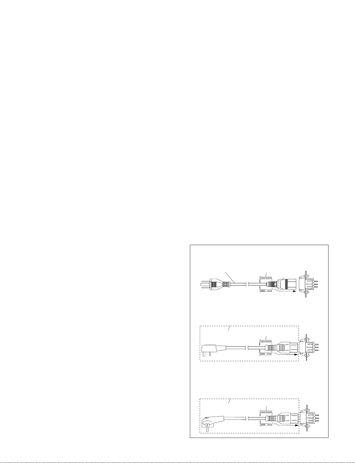
Table of Contents
1. Installation
1-1. Power Supply ........................................................................................1-1 (E)
1-1-1. Power Specifications ............................................................1-1 (E)
1-1-2. Power Cord...........................................................................1-1 (E)
1-2. Dimensions............................................................................................1-2 (E)
1-3. Installation of Boards ............................................................................1-2 (E)
1-4. Rack Mounting......................................................................................1-3 (E)
1-5. Pin Assignment of Connectors..............................................................1-4 (E)
1-6. Matching Connectors and Cables..........................................................1-5 (E)
1-7. Internal Switches ...................................................................................1-5 (E)
1-7-1. AL-42 Board (BKAM-101) .................................................1-5 (E)
1-7-2. SDI-43 Board (BKAM-103) ................................................1-5 (E)
1-8. Input Level Meter Adjustment .............................................................1-6 (E)
1-9. Related manuals ....................................................................................1-6 (E)
Section 1
Installation
1-1. Power Supply
1-1-1. Power Specifications
Power voltage AC 100 to 240 V ±10 %
Current consumption 25 W
Inrush current 20 A
1-1-2. Power Cord
w
Use the specified power cord only when connecting.
Never use a injured power cord.
n
Ground the unit safely.
If the unit is used in the area except above, please consult
with local Sony’s sales/service office.
Power code for the customer in the U.S.A.and Canada.
1 Power cord (approx. 2.4 m) ! 1-557-377-11
2 Plug holder (Black) 2-990-242-01
1
Power code for the customer in the United Kingdom.
1 Power cord set (approx. 2.4 m) ! DK-2401 (UK)
2 Plug holder (Black) 2-990-242-01
Plug holder is supplied with DK-2401 (UK).
1
Power code for the customer in Europe except the United
Kingdom.
1 Power cord set (approx. 2.4 m) ! DK-2401 (AE)
2 Plug holder (Black) 2-990-242-01
Plug holder is supplied with DK-2401 (AE).
1
2
2
2
AC inlet
AC inlet
AC inlet
AMS-100
1-1(E)
Page 4

1-2. Dimensions
1-3. Installation of Boards
1-2. Dimensions
350
5
424
465
482
1-3. Installation of Boards
The optional boards (BKAM-101/102/103) can be installed in any slots of the AMS-100.
Installation of optional boards
1. Turn off the power of the AMS-100.
2. Remove the blank panel on the rear panel after
removing its two retainer screws.
n
Do not discard the removed blank panel.
3. Slide the optional board along the guide rails into the
unit.
4. Secure the optional board in the AMS-100 with the
screws supplied with the optional board.
n
If there is any unused slot without a cover, install the
cover you have just removed there.
Blank panel
B 3x5
Unit : mm
1-2(E)
B 3x5
BKAM-101, BKAM-102, BKAM-103
AMS-100
Page 5

1-4. Rack Mounting
1-4. Rack Mounting
The AMS-100 can be mounted in a 19-inch standard rack.
n
. If the AMS-100 or the peripheral equipment is mounted
in a 19-inch standard rack, it is recommended to install a
ventilation fan to prevent a temperature rise in the rack.
Make sure that all the units in the rack should be operated within the temperature range of 5dC to 40dC.
. Connect the enough long cables on the rear panel,
considering that the AMS-100 is pulled out.
. Be sure to fix the rack to the floor with bolts.
This will prevent the rack from falling when the unit is
pulled out from the rack.
Required parts
. Rack mount rail (RMM-30)
Rail with bracket : 2 pcs.
Screw (B5x8) : 4 pcs.
Screw (PWH4x10) : 2 pcs.
Plate nut : 2 pcs.
. Screw for inner rail (B4x8) : 6 pcs.
. Screw for rack mounting (RK5x16) : 4 pcs.
. Washer for rack mounting : 4 pcs.
(Sony part number : 2-297-913-00)
c
Be sure to use the RMM-30 rack mount rail.
If a rack mount rail other than the RMM-30 is used, the
AMS-100 may be dropped by insufficient strength of the
rack mount rail. This may cause a injury.
Procedures
1. Turn off the power.
2. Attach the inner rails to the unit using the six screws
(B4x8) supplied with the RMM-30.
Inner rail
B 4x8
Inner rail
B 4x8
3. Temporarily fix the front and rear brackets to the rack
by running in but not tightening the four screws
(B5x8) and two screws (PWH4x10) supplied with the
RMM-30.
Plate nut
12.7
15.9
15.9
12.7
15.9
15.9
Front bracket
PWH 4x10
Rack
AMS-100
Rear bracket
31.75
B 5x8
_To be continued on the next page._
1-3(E)
Page 6

1-4. Rack Mounting
1-5. Pin Assignment of Connectors
4. To mount the unit on the rack, while pressing the
stoppers of the inner rails, slide the inner rails fully
into the outer rails.
5. After confirming that the unit can be moved smoothly,
tighten the six screws run in but not tightened in
procedure 3.
n
To tighten the front brackets to the rack, slide the unit
from the rack toward you about 20 mm.
6. After mounting the unit on the rack, fix the unit to the
rack with the four screws (RK5x16) and four washers.
Washer
RK 5x16
Outer rail
Stopper
RK 5x16
Washer
Inner rail
1-5. Pin Assignment of Connectors
REMOTE (D-sub 25-pin, Female)
13 1
25
_External View_
Pin No. Signal
1 REM-A IN
2 REM-B IN
3 REM-CH.SELECT L1 IN
4 REM-CH.SELECT L2 IN
5 REM-CH.SELECT R1 IN
6 REM-CH.SELECT R2 IN
7 GND
8 MONITOR OUT 2(H)
9 MONITOR OUT 2(C)
10 MONITOR OUT 1(H)
11 MONITOR OUT 1(C)
12 REM-GROUP SEL. 1 IN
13 REM-GROUP SEL. 2 IN
14 STS-A OUT
15 STS-B OUT
16 STS-CH. SELECT L1 OUT
17 STS-CH. SELECT L2 OUT
18 STS-CH. SELECT R1 OUT
19 STS-CH. SELECT R2 OUT
20 STS-GROUP SEL. 1 OUT
21 MONITOR OUT 2(G)
22 REM-ENABLE 2 IN
23 MONITOR OUT 1(G)
24 STS-GROUP SEL. 2 OUT
25 REM-ENABLE 1 IN
14
1-4(E)
AMS-100
Page 7

1-6. Matching Connectors and Cables
1-7. Internal Switches
1-6. Matching Connectors and Cables
When connecting cables to various connectors on the rear
panel at the time of installing or servicing, connect the
following connectors/cables or their equivalents.
Connector Matching Connector/cable
Panel indication Connector/Cable Sony Part No.
REMOTE D-sub 25-pin, male 1-566-356-11
AUDIO IN 1 XLR 3-pin, male 1-508-084-00 (*1)
XLR 3-pin, female 1-508-083-00 (*2)
AUDIO IN 2 XLR 3-pin, male 1-508-084-00 (*1)
XLR 3-pin, female 1-508-083-00 (*2)
DIGITAL AUDIO IN XLR 3-pin, female 1-508-083-00 (*2)
BNC 75 Z, male 1-560-370-12
5C-2V cable (*3)
SDI IN BNC 75 Z, male 1-560-370-12
SDI OUT 5C-2V cable (*3)
(*1) : ITT Cannon XLR-3-12C or equivalent
(*2) : ITT Cannon XLR-3-11C or equivalent
(*3) : 5C-2V coaxial cable (max. 200 m)
It is recommended to use the 5C-2V coaxial cable made by Fujikura
America Inc./Fujikura Europe Ltd. (FEL) or equivalent.
1-7. Internal Switches
1-7-2. SDI-43 Board (BKAM-103)
CN101
S102S101
S103
S101 : Free-run adjustment select switch for the
serial decoder
Used during free-run adjustment of the serial decoder:
OFF : Normal operation
ON : For free-run adjustment
Factory setting : OFF
1-7-1. AL-42 Board (BKAM-101)
CN101
S2
S2: CH-1 input level select switch
To select the input level of CH-1.
Factory setting : +4 dB
S22: CH-2 input level select switch
To select the input level of CH-2.
Factory setting : +4 dB
AMS-100
S22
S102 : Video system select switch
To select the video system (525/625).
(Effective for 4:2:2 component serial video signal mode)
525 : For a 525 video system
625 : For a 625 video system
Factory setting : 525
S103 : Mode select switch
ON
1234
( Indicates the switch lever position.)
S103-1 : D1/D2 system selector
To select the video system used:
OFF (D1) : 4:2:2 component serial video signal
ON (D2) : 4fsc composite serial video signal
S103-2, -3, -4 : For factory-adjustment use only.
n
Do not change the factory presetting of
these switches.
Factory setting : all OFF
1-5(E)
Page 8

1-8. Adjustment of the Input Level Meter
1-9. Related manuals
1-8. Input Level Meter Adjustment
Preparation
. Input the reference signal to the unit:
When the BKAM-101 is attached : +4 dBm
When the BKAM-102 is attached : _20 dB FS
. Turn on the power of the unit and select the slot and the
channel to which the reference signal is to be input on
the INPUT SELECT operation panel.
(For details on operation, refer to the Operation Manual.)
. Let the unit warm up for about 10 minutes.
Adjustment procedures
1. Press and hold the button corresponding to the desired
slot for 3 seconds or more on the INPUT SELECT
operation panel to enter Adjustment mode.
2. Check that the LED for the channel you are selecting
starts blinking.
3. Perform the following adjustment.
Adj. point : Adjustment screw L/input level meter
Adjustment screw R/input level meter
Specification : The LEDs for “0” level start blinking.
1-9. Related manuals
Besides this Installation Manual, the following manuals are
available for the AMS-100.
. Operation Manual (Supplied with the AMS-100)
This manual explains the overview of the AMS-100, and
the system configuration examples.
. Maintenance Manual (available on request)
This manual describes information that premise the
service based on parts replacement (adjustments, board
layouts, schematic diagrams, parts list, etc.).
If this manual is required, contact your local Sony Sales
Office/Service Center.
LEDs for "0" level
LR
+3
+1
0
_1
_3
_5
_7
_10
_15
_20
Adjustment screws
_10
_15
_20
+3
+1
0
_1
_3
_5
_7
Setting after adjustment
To return from Adjustment mode, press any button on the
INPUT SELECT operation panel.
1-6(E)
AMS-100
Page 9

SAFETY CHECK-OUT
After correcting the original service problem,
perform the following safety checks before
releasing the set to the customer :
The material contained in this manual consists of
information that is the property of Sony Corporation and
is intended solely for use by the purchasers of the
equipment described in this manual.
Sony Corporation expressly prohibits the duplication of
any portion of this manual or the use thereof for any
purpose other than the operation or maintenance of the
equipment described in this manual without the express
written permission of Sony Corporation.
Le matériel contenu dans ce manuel consiste en
informations qui sont la propriété de Sony Corporation et
sont destinées exclusivement à l’usage des acquéreurs
de l’équipement décrit dans ce manuel.
Sony Corporation interdit formellement la copie de
quelque partie que ce soit de ce manuel ou son emploi
pour tout autre but que des opérations ou entretiens de
l’équipement à moins d’une permission écrite de Sony
Corporation.
Das in dieser Anleitung enthaltene Material besteht aus
Informationen, die Eigentum der Sony Corporation sind,
und ausschließlich zum Gebrauch durch den Käufer der
in dieser Anleitung beschriebenen Ausrüstung bestimmt
sind.
Die Sony Corporation untersagt ausdrücklich die
Vervielfältigung jeglicher Teile dieser Anleitung oder den
Gebrauch derselben für irgendeinen anderen Zweck als
die Bedienung oder Wartung der in dieser Anleitung
beschriebenen Ausrüstung ohne ausdrückliche
schriftliche Erlaubnis der Sony Corporation.
Check the metal trim, “metallized” knobs, screws,
and all other exposed metal parts for AC
leakage. Check leakage as described below.
LEAKAGE TEST
The AC leakage from any exposed metal part to
earth ground and from all exposed metal parts to
any exposed metal part having a return to
chassis, must not exceed 3.5 mA. Leakage
current can be measured by any one of three
methods.
1. A commercial leakage tester, such as the
Simpson 229 or RCA WT-540A. Follow the
manufacturers’ instructions to use these
instruments.
2. A battery-operated AC milliammeter. The
Data Precision 245 digital multimeter is
suitable for this job.
3. Measuring the voltage drop across a resistor
by means of a VOM or battery-operated AC
voltmeter. The “limit” indication is 5.25 V, so
analog meters must have an accurate lowvoltage scale. The Simpson 250 and Sanwa
SH-63Trd are examples of a passive VOM
that is suitable. Nearly all battery operated
digital multimeters that have a 20 V AC range
are suitable. (See Fig. A)
To Exposed Metal
Parts on Set
0.15
µ
F 1.5 k
Fig A. Using an AC voltmeter to check AC leakage.
Z
Earth Ground
AC
voltmeter
(5.25V)
Page 10

AMS-100 (SY)
BKAM-101 (SY)
BKAM-102 (SY)
BKAM-103 (SY) J, E
3-202-309-01
Printed in Japan
Sony Corporation 1999. 2 11
Broadcasting & Professional Systems Company ©1999
 Loading...