

Sony Betacam SX DNW-A28, Betacam SX DNW-A28P Operation Manual

DIGITAL VIDEOCASSETTE RECORDER
DNW-A28/A28P
OPERATION MANUAL
1st Edition (Revised 3)
[English]

WARNING
To prevent fire or shock hazard, do not
expose the unit to rain or moisture.
To avoid electrical shock, do not open the
cabinet. Refer servicing to qualified
personnel only.
For the customers in the USA
For the customers in Europe
This product with the CE marking complies with the EMC
Directive (89/336/EEC) issued by the Commission of the
European Community.
Compliance with this directive implies conformity to the
following European standards:
• EN55103-1: Electromagnetic Interference (Emission)
• EN55103-2: Electromagnetic Susceptibility (Immunity)
This product is intended for use in the following
Electromagnetic Environment (s):
E1 (Residential), E2 (Commercial and light industrial), E3
(Urban outdoors) and E4 (Controlled EMC environment ex.
TV studio)
This equipment has been tested and found to comply with
the limits for a Class B digital device, pursuant to Part 15 of
th e FCC Rules. These limits are designed to provide
reasonable protection against harmful interference in a
residential installation. This equipment generates, uses,
and can radiate radio frequency energy and, if not installed
and used in accordance with the instructions, may cause
harmful interference to radio communications. However,
there is no guarantee that interference will not occur in a
particular installation. If this equipment does cause harmful
interference to radio or television reception, which can be
determined by turning the equipment off and on, the user is
encouraged to try to correct the interference by one or
more of the following measures:
— Reorient or relocate the receiving antenna.
— Increase the separation between the equipment and
receiver.
— Connect the equipment into an outlet on a circuit
different from that to which the receiver is connected.
— Consult the dealer or an experienced radio/TV
technician for help.
You are cautioned that any changes or modifications not
expressly approved in this manual could void your authority
to operate this equipment.
The shielded interface cable recommended in this manual
must be used with this equipment in order to comply with
the limits for a digital device pursuant to Subpart B of Part
15 of FCC Rules.
Pour les clients européens
Ce produit portant la marque CE est conforme à la
Directive sur la compatibilité électromagnétique (EMC) (89/
336/CEE) émise par la Commission de la Communauté
européenne.
La conformité à cette directive implique la conformité aux
normes européennes suivantes:
• EN55103-1: Interférences électromagnétiques (émission)
• EN55103-2: Sensibilité électromagnétique (immunité)
Ce produit est prévu pour être utilisé dans les
environnements électromagnétiques suivants:
E1 (résidentiel), E2 (commercial et industrie légère), E3
(urbain extérieur) et E4 (environnement EMC contrôlé ex.
studio de télévision).
Für Kunden in Europa
Dieses Produkt besitzt die CE-Kennzeichnung und erfüllt
die EMV-Direktive (89/336/EEC) der EG-Kommission.
Die Erfüllung dieser Direktive bedeutet Konformität für die
folgenden Europäischen Normen:
• EN55103-1: Elektromagnetische Interferenz (Emission)
• EN55103-2: Elektromagnetische Empfindlichkeit
(Immunität)
Dieses Produkt ist für den Einsatz unter folgenden
elektromagnetischen Bedingungen ausgelegt:
E1 (Wohnbereich), E2 (kommerzieller und in beschränktem
Maße industrieller Bereich), E3 (Stadtbereich im Freien)
und E4 (kontrollierter EMV-Bereich, z.B. Fernsehstudio)

Table of Contents
Chapter 1
Overview
Chapter 2
Preparations
1-1 Features ........................................................................................... 1-1
1-2 System Configuration ................................................................... 1-3
1-3 Locations and Functions of Parts ................................................ 1-4
1-3-1 Front Panel............................................................................ 1-4
1-3-2 Rear Panel........................................................................... 1-12
2-1 Power Preparations......................................................................... 2-1
2-1-1 Usable Batteries ...................................................................... 2-1
2-1-2 Using the BP-L60(A)/L90(A) Battery Pack ........................... 2-1
2-1-3 Using the BP-90(A) Battery Pack........................................... 2-2
2-1-4 Using AC Power ..................................................................... 2-2
2-2 Connection ....................................................................................... 2-4
2-3 Handling Cassettes .......................................................................... 2-5
2-3-1 Loading/Ejecting Cassettes.................................................... 2-5
2-3-2 Preventing Accidental Erasures.............................................. 2-6
2-4 Setting Reference Video Signals .................................................... 2-7
2-5 Information Displayed on the Monitor ......................................... 2-9
2-6 Setting Timecode ........................................................................... 2-12
2-6-1 Setting an Initial Value and Recording Timecode................ 2-12
2-6-2 Synchronizing the Internal Timecode Generator with an
External Signal..................................................................... 2-14
2-6-3 Synchronizing the Internal Timecode Generator with
Playback Timecode–Timecode Recording during Auto
Editing.................................................................................. 2-15
2-6-4 Recording External Timecode without Regeneration........... 2-15
2-7 Submenu......................................................................................... 2-16
2-7-1 Displays on the Home Page of the Submenu........................ 2-16
2-7-2 Submenu Basic Operations................................................... 2-18
2-8 Input and Output Settings for Video and Audio Signals
(Submenu) ..................................................................................... 2-20
2-8-1 Making Settings in the Audio Settings Pages....................... 2-20
2-8-2 Making Settings in the Audio Settings Subpage .................. 2-21
2-8-3 Making Settings in the Video Settings Pages ....................... 2-22
2-9 General Settings Page of the Submenus...................................... 2-24
Chapter 3
Editing
3-1 Selecting an Edit Mode .................................................................. 3-1
3-1-1 Assemble Editing.................................................................... 3-1
3-1-2 Insert Editing ........................................................................ 3-1
3-2 Finding Edit Points – Search........................................................ 3-3
3-3 Manual Editing.............................................................................. 3-4
3-4 Preread Editing ............................................................................. 3-5
Table of Contents 1

Table of Contents
Chapter 4
Recording and Playback
Chapter 5
Shot Mark/Shot Data
4-1 Recording ........................................................................................ 4-1
4-1-1 Preparations for Recording ..................................................... 4-1
4-1-2 Recording Operation............................................................... 4-1
4-2 Sequential Recording ..................................................................... 4-2
4-3 Back Space Editing ........................................................................ 4-3
4-4 Playback ......................................................................................... 4-4
4-4-1 Preparations for Playback ....................................................... 4-4
4-4-2 Playback Operation................................................................. 4-4
4-4-3 Capstan Override Playback..................................................... 4-5
5-1 Overview of Shot Mark/Shot Data Function ............................... 5-1
5-1-1 Shot Mark Function Features ................................................. 5-1
5-1-2 Shot Mark Operation Menu .................................................. 5-2
5-1-3 Reading Shot Data ................................................................ 5-3
5-2 Shot Mark Operations .................................................................. 5-4
5-2-1 Reading Shot Marks ............................................................... 5-4
5-2-2 Writing Shot Marks ................................................................ 5-4
5-2-3 Creating a Virtual Shot Mark ................................................. 5-5
5-2-4 Displaying Shot Mark List ..................................................... 5-5
5-2-5 Deleting Shot Marks ............................................................... 5-6
5-2-6 Sorting Shot Marks ................................................................. 5-7
5-2-7 Cueing up a Mark ................................................................... 5-7
Chapter 6
Setup Menu
Appendixes
6-1 Menu System Configuration ......................................................... 6-1
6-2 Basic Menu..................................................................................... 6-1
6-2-1 Items in the Basic Menu ....................................................... 6-1
6-2-2 Basic Menu Operations......................................................... 6-4
6-3 Extended Menu.............................................................................. 6-8
6-3-1 Items in the Extended Menu ................................................. 6-8
6-3-2 Extended Menu Operations ................................................ 6-22
Removing a Cassette When Tape Slack Occurs ................................ A-1
Head Cleaning....................................................................................... A-1
Error Messages ..................................................................................... A-2
Moisture Condensation ........................................................................ A-3
Regular Checks ..................................................................................... A-3
Digital Hours Meter ........................................................................ A-3
Replacing Components ................................................................... A-4
Specifications......................................................................................... A-5
Glossary ................................................................................................. A-9
Index ........................................................................................................I-1
2 Table of Contents

1-1 Features
Chapter 1 Overview
The DNW-A28/A28P is a digital portable
videocassette recorder for the Betacam SX format.
The features of this unit include the following.
Betacam SX format
This unit supports the Betacam SX format, developed
by Sony as the digital version of the Betacam SP
format. No format conversion is needed for use with
nonlinear editing systems and server systems.
Playback compatibility with Betacam SP
It can play tapes recorded in the Betacam and Betacam
SP formats, allowing you to make effective use of
Betacam and Betacam SP cassettes recorded in the
past. You can assemble news gathering systems that
combine this unit with conventional Betacam SP
camcorders.
Sequential recording
Connecting two DNW-A28/A28P units allows you to
perform sequential recording from one unit to another.
When you perform overwrite recording using only two
cassettes, the last two hours recording can be obtained
at any time. When you renew the cassette about every
1 hour, endless recording is possible.
Good Shot marks/Shot Data
During tape rewinds, this unit reads the REC Start
(RS) and Good Shot (GS) marks recorded by Betacam
SX camcorders, and builds an index. The index
facilitates quick cue-ups of desired marks (index
search function), for greater editing efficiency.
When shot marks are recorded on the tape, you can
display and sort lists of the shot marks.
Preread editing
Chapter 1 Overview
Digital signal processing
This unit processes 4:2:2 component digital signals in
the D-1 format.
Inter-frame data compression
Inter-frame data compression by MPEG2 4:2:2 Profile
@ Main Level (1 GOP = 2 frames) reduces the volume
of data to about
1
/10.
Rich variety of input and output signals
The following input and output signals are supported.
• SDI (serial digital interface) video and audio
• Analog composite video
• Analog audio
• Timecode
Powerful editing functions
You can use video or audio signals recorded on the
tape as the edit source for insert editing because this
unit uses the preread heads to read the signals in
advance. This type of editing is called “preread
editing”.
Back space editing
To record multiple scenes as a single sequence, you
can use the PAUSE button to record the scenes
continuously with no noise or breakup between scenes.
AC and DC power
The BP-L60(A)/L90(A) or BP-90(A) battery or an AC
adaptor can be used on this unit. The unit can operate
for about 80 minutes with a BP-L90 battery mounted.
For AC operation, you can connect an AC-550/550CE
or AC-DN2A adaptor.
To mount a battery or the AC-DN2A on this unit,
attach the optional BKP-L551 Battery Adaptor.
By connecting two DNW-A28/A28P units to a BVEseries or other editor, you can perform assemble
editing, insert editing, and audio split editing. When
both the source and recording sides use the Betacam
SX format, you can perform DMC editing.
You can also perform editing by connecting this unit to
a VTR such as the DNW-A100/A75 series.
Chapter 1 Overview 1-1

Features
525 or 625 versatility
Chapter 1 Overview
When using the Betacam SX format, 525 or 625 mode
recording and playback can be selected from a menu.
When using the Betacam and Betacam SP formats,
only simple viewing is possible for tapes recorded in
different mode.
Other
•Betacam SP cassettes and inexpensive UVW
cassettes can be used in addition to Betacam SX
cassettes.
•Special high-durability heads and components
contribute to reduced maintenance costs.
•You can stack up to three DNW-A28/A28P units for
use in recording and editing.
1-2 Chapter 1 Overview
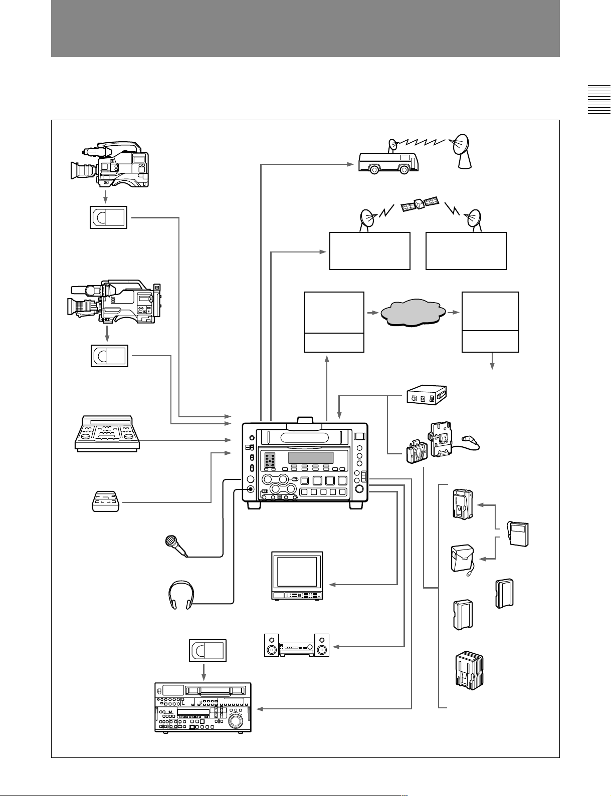
1-2 System Configuration
The figure below shows an example of an editing
system configured around the DNW-A28/A28P.
Betacam SX camcorder
Digital
cassette
Chapter 1 Overview
SDI
Microwave transmission system
Betacam SP camcorder
Analog
cassette
BVE series editor
BVR-3
REMOTE/DC OUT
REMOTE
Microphone
SDI
Protocol
converter
DSM-M1
SDI
DNW-A28/A28P
Digital
modulator
BATTERY/
DC IN
Network
AC-550/550CE
Digital
demodulator
Protocol
converter
DSM-D1
SDI
BKP-L551
DC-L90
Headphones
Digital cassette
DNW-A100/A75 series
Video monitor
Audio monitor
VIDEO
OUT
MONITOR OUT/
AUDIO OUT
BP-90(A)
DC-210
BP-L60(A)
BP-L90(A)
AC-DN2A
Chapter 1 Overview 1-3
Chapter 1 Overview
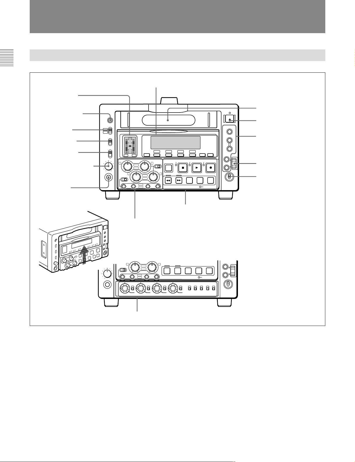
1-3 Locations and Functions of Parts
1-3-1 Front Panel
1 Submenu operation section (page 1-5)
5 Audio level meter
6 WARNING indicator
7 METER switch
8 REC INHI switch
9 MONITOR switch
0 Monitor audio level knob
!¡ PHONES jack
WARNING
METER
1/2
3/4
INHI
REC
ON
OFF
MONITOR
1/2
MIX
2/1
PHONES
PHONES
OVER OVEREMPH
PEAK
1/3 2/4
dB
REC
PB
PRE VAR
REC
1 3 4
2
PB
TC 525 SX-- BATT
00:00:00:00
AU-1 AUTO VITCON SDI
F1
PAGE
SHIFT
21
PRE VAR
43
REC
PB
REW
F2 F3 F4
STANDBY
F FWD SEARCH EDIT PAUSE
5 Audio control section (page 1-11)
43
REW
PRE VAR
1 3 4
VIDEO
REC
PB
REC
2
PB
PRE
PRE
VAR
VAR
CHROMA TC GENERATOR
SET UP/BLACK LEVEL CHROMA PHASE
F FWD SEARCH EDIT PAUSE
PRE
VAR
EJECT
CTL/TC/U-BIT
HOLD
LIST MARK
UP
DOWN
REC
INHI
SERVO
STOP DATA PLAY SEQ REC
EDIT PRESET
SET
MENU
POWER
RESET
PUSH
ON
OFF
3 Tape transport section (page 1-7)
SET
MENU
POWER
PUSH
ON
OFF
EDIT PRESET
PRE
LOCAL
INT
PRESET
F-RUN
VAR
REMOTE
EXT
REGEN
R-RUNPBPB/EE
1 Cassette compartment
2 EJECT button
2 Timecode/setup menu
operation section (page 1-6)
3 Jog dial
4 POWER switch
4 Lower control panel (page 1-9)
1 Cassette compartment
Insert a cassette here.
2 EJECT button
Press to eject the cassette. The button lights while the
cassette is being ejected. If you insert a cassette which
cannot be used on this unit, the button flashes. Press
the button to eject the cassette.
1-4 Chapter 1 Overview
3 Jog dial
Use to carry out searches in jog or shuttle mode and
for menu operations. Rotate downward to search in the
forward direction, and upward to search in the reverse
direction. For menu operations, rotate to select a menu
item and press to confirm the selection.
For more information about search and menu operations,
see section 3-2 “Finding Edit Points – Search” and Chapter
6 “Setup Menu”.

4 POWER switch
Powers the unit on and off.
5 Audio level meter
Displays the recording and playback audio levels of
two (CH-1/2 or CH-3/4) of the four audio channels
(CH-1 to CH-4), as selected with the METER switch
7.
6 WARNING indicator
Lights when the battery is exhausted or an error
occurs.
It flashes in the following cases.
•When the end of battery power is near
•When the number of memorized shot marks reaches
to 200 during shot mark reading or when you start
reading shot marks after 200 marks have been read.
8REC INHI switch
When ON, recording to the tape is inhibited, regardless
of the state of the cassette’s erasure prevention plug.
(The REC INHI indicator lights.)
9MONITOR switch
Selects the output from the MONITOR OUTPUT L/R
connectors. Settings made with this switch are enabled
only when audio settings page 1-3 is selected.
1/2: Output the audio signals of channel 1 from the L
connector and the audio signals of channel 2 from
the R connector.
MIX: Output the mixed signals of channels 1 and 2
from both the L and R connectors.
2/1: Output the audio signals of channel 2 from the L
connector and the audio signals of channel 1 from
the R connector.
Chapter 1 Overview
7 METER switch
Selects the audio channel whose level is displayed by
the audio level meter.
CH-1/2: Display the recording, playback, and E-E
levels of audio channels 1 and 2.
CH-3/4: Display the recording, playback, and E-E
levels of audio channels 3 and 4.
1 Submenu Operation Section
Settings made by submenu include video and audio input
and output settings, and reference video signal settings. For
details, see section 2-7-1 “Displays on the Home Page of
the Submenu”.
TC 525 SX-- BATT
00:00:00:00
AU-1 AUTO VITCON SDI
F1
PAGE
F2 F3 F4
0 Monitor audio level knob
Adjusts the volume of the headphones connected to the
PHONES jack !¡.
This knob can also adjust the level of the audio signal output
from the MONITOR OUT connectors when MONITOR in
the submenu is set to VAR. For details, see page 2-21.
!¡ PHONES (headphones) jack
Connect headphones.
1 FL display panel
LIST MARK
UP
DOWN
3 Operation buttons F1 to
F4
2 PAGE button
5 MARK/UP button
4 LIST/DOWN button
Chapter 1 Overview 1-5
Locations and Functions of Parts
Chapter 1 Overview
1 FL (fluorescent) display panel
Displays time data, status information, submenu, setup
menu and error messages.
2 PAGE button
Switches between pages in the submenu.
3 Operation buttons F1 to F4
Select items in the submenu.
You can use operation button F4 for preroll (see “!º
Source video signal display” on page 2-17).
4 LIST/DOWN button
Press to make settings in the submenu.
5 MARK/UP button
Press to make settings in the submenu.
2 Timecode/setup menu operation
section
3 RESET button
Resets the CTL, TC, and U-BIT values displayed in
the FL display panel to 0. Resetting the CTL value
erase all edit points that have been set.
For more information, see section 2-6 “Setting Timecode”.
4 SET button
Use to make setup menu settings, timecode settings,
and user bit settings.
For more information about setup menu operations, see
Chapter 6, “Setup Menu”. For more information about
timecode and user bit settings, see 2-6 “Setting Timecode”.
5 MENU button
Use for setup menu operations. The setup menu
appears on the monitor connected to the VIDEO
OUTPUT 2 (SUPER) connector and FL display panel
when you press this button with the SUPER in the
submenu set to other than OFF (see page 2-24), and
the original display appears when you press it again.
CTL/TC/U-BIT
1 CTL/TC/U-BIT button
HOLD
2 HOLD button
RESET
3 RESET button
SET
4 SET button
MENU
5 MENU button
1 CTL/TC/U-BIT button
Alternately selects CTL (control), TC (timecode), and
U-BIT (user bits) as the time data used in editing and
displayed in the FL display panel.
2 HOLD button
Stops the progress of the timecode generator. Press this
button before setting timecode or user bits to hold
those values.
For more information about setup menu operations, see
Chapter 6, “Setup Menu”.
For more information, see section 2-6 “Setting Timecode”.
1-6 Chapter 1 Overview
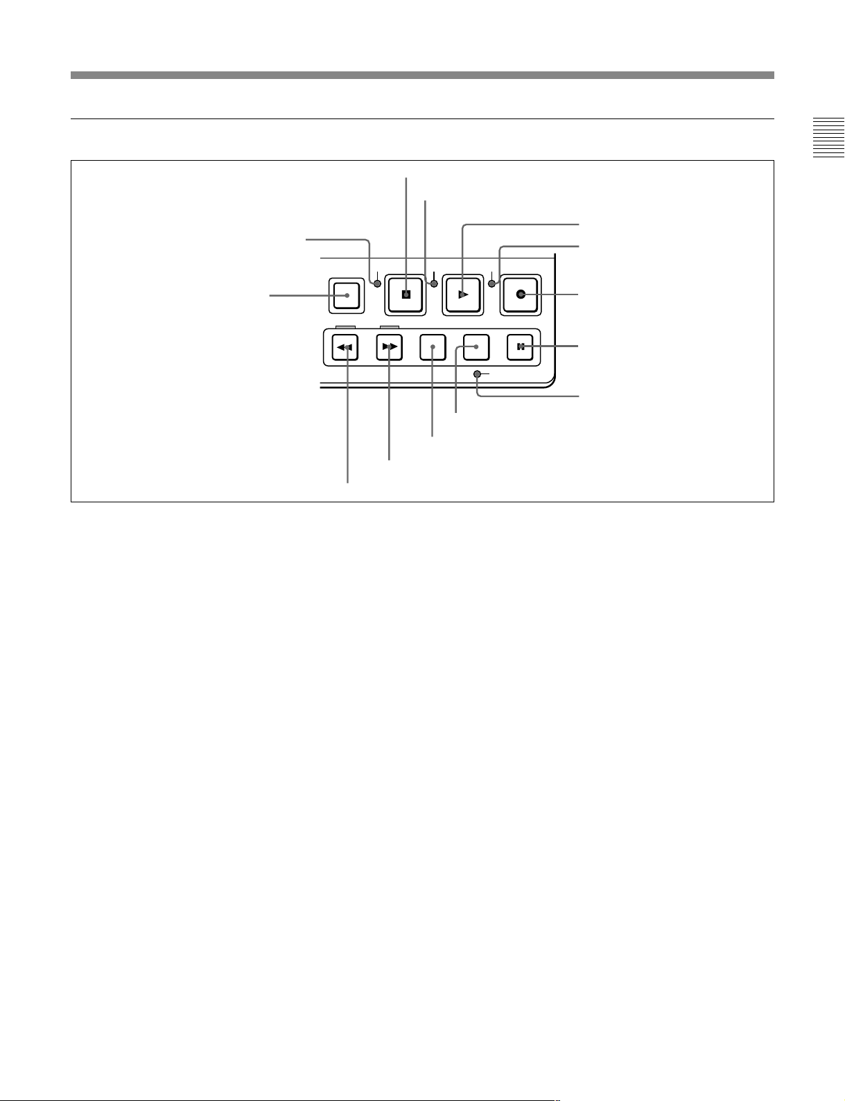
3 Tape transport section
2 STANDBY indicator
SHIFT
STANDBY
1 SHIFT button
REW
F FWD SEARCH EDIT PAUSE
!£ REW button
1 SHIFT button
Switches between functions for buttons with two
functions. The following buttons have two functions.
LIST/DOWN button: Becomes the LIST button
when the SHIFT button is pressed.
MARK/UP button: Becomes the MARK button
when the SHIFT button is pressed.
DATA/PLAY button: Becomes the DATA button
when the SHIFT button is pressed.
SEQ/REC button: Becomes the SEQ button when
the SHIFT button is pressed.
3 STOP button
4 SERVO indicator
REC
SERVO
STOP DATA PLAY SEQ REC
!¡ SEARCH button
!™ F FWD button
INHI
EDIT PRESET
0 EDIT button
3 STOP button
Press this button, lighting it, to stop playback or
recording. When you stop playback, the monitor
displays E-E or still picture playback, depending on
the settings of the monitor output switches in the
timecode and setup menu section.
When setup menu item 105 is set to ON (page 6-8),
this button flashes if the reference video signal
specified in the OUT REF item of the submenu (page
2-22) and item 309 in the setup menu (page 6-11) is
not being input.
Chapter 1 Overview
5 DATA/PLAY button
6 REC INHI indicator
7 SEQ/REC button
8 PAUSE button
9 EDIT PRESET indicator
2 STANDBY indicator
Lights when the tape drum is rotating with tension
applied (standby on). It goes out when the drum stops
rotating and tension is released (standby off).
To protect the tape, the unit normally changes to
standby off when stop or pause mode continues for
longer than eight minutes. If you operate a dial or any
of the tape transport buttons except STOP/PAUSE
while the unit is in this state, the unit changes to
standby on and enters the mode of the button or dial
that you pressed.
Press the SHIFT and STOP buttons at the same time to
switch from standby on to standby off manually.
For more information about tape protection, see the setup
menu items in the 500s on page 6-13.
For more information about reference video signal settings,
see page 2-7.
4 SERVO indicator
Lights when the drum servo and capstan servo are
locked.
5 DATA/PLAY button
Press this button, lighting it, to start playback.
Recording starts when you press this button together
with the SEQ/REC button 7, and manual editing
starts when you press this button together with the
EDIT button 0. If you press this button only during
recording or manual editing, recording or manual
editing stops and the unit returns to playback mode.
This button is also used to display the shot data if it is
recorded on the tape.
For details, see 5-1-3 “Reading Shot Data”.
Chapter 1 Overview 1-7

Locations and Functions of Parts
Chapter 1 Overview
6 REC INHI (recording inhibit) indicator
Lights under the following situations.
•Set the REC INHI switch to ON.
•Press in the erasure prevention plug.
•Insert the Betacam cassette (oxide tape).
When the REC INHI switch is set to OFF, it is possible to
set this indicator flashing instead of lighting under the latter
two situations. For details, see setup menu item 107 on
page 6-8.
7 SEQ/REC (sequence/recording) button
Press together with the DATA/PLAY button 5 to
start recording.
When two DNW-A28/A28P units are connected, this
button allows you to perform sequential recording
from one unit to another.
For details, see 4-2 “Sequential Recording”.
To monitor E-E mode
You can monitor input signals in E-E mode by
pressing this button from stop mode. The button lights
when pressed. To return to the original picture, press
the STOP button 3. You can view E-E video during
playback, search, fast forward, and rewind by pressing
this button. The E-E video continues for as long as the
button is kept pressed.
8 PAUSE button
Pauses the operation when pressed during recording or
playback. You can execute continuous operations by
pressing this button together with the SEQ/REC button
7 and the DATA/PLAY button 5.
Press together with the DATA/PLAY button 5 to
perform manual editing.
To monitor E-E mode
You can monitor input signals in E-E mode by
pressing this button from stop mode. The button lights
when pressed, and the input signals selected in the Edit
Preset menu appear in E-E mode. To return to the
original picture, press the STOP button 3. You can
view E-E video during playback, search, fast forward,
and rewind by pressing this button. The E-E video
continues for as long as the button is kept pressed.
!¡ SEARCH button
Press to enter search mode. When the unit is in jog
mode, keep this button depressed for about 1 second to
enter shuttle mode, and vice versa.
In shuttle mode, you can start playback at preset speed
by rotating the jog dial to the desired position and
pressing this button.
For details on mode change, see the section 3-2 “Finding
Edit Points – Search”
!™ F FWD (fast forward) button
Press this button, lighting it, to fast forward the tape.
When using a tape on which shot marks have been
recorded, you can press this button together with the
LIST/DOWN button to read shot marks from the tape,
and press this button together with the MARK/UP
button to cue up shot mark positions.
For details, see Chapter 5 “Shot Mark/Shot Data”.
For more information about continuous recording, see
section 4-3 “Back Space Editing”.
9 EDIT PREST (preset) indicator
Lights when an item in the Edit Preset menu is set to
ON.
For more information about the Edit Preset menu, see
section 3-1 “Selecting an Edit Mode”.
0 EDIT button
Press this button to display the Edit Preset menu in the
FL display panel, allowing you to select an edit mode.
For more information about the Edit Preset menu, see
section 3-1 “Selecting an Edit Mode”.
1-8 Chapter 1 Overview
!£ REW (rewind) button
Press this button, lighting it, to rewind the tape.
When using a tape on which shot marks have been
recorded, you can press this button together with the
LIST/DOWN button to read shot marks from the tape,
and press this button together with the MARK/UP
button to cue up shot mark positions.
For details, see Chapter 5 “Shot Mark/Shot Data”.
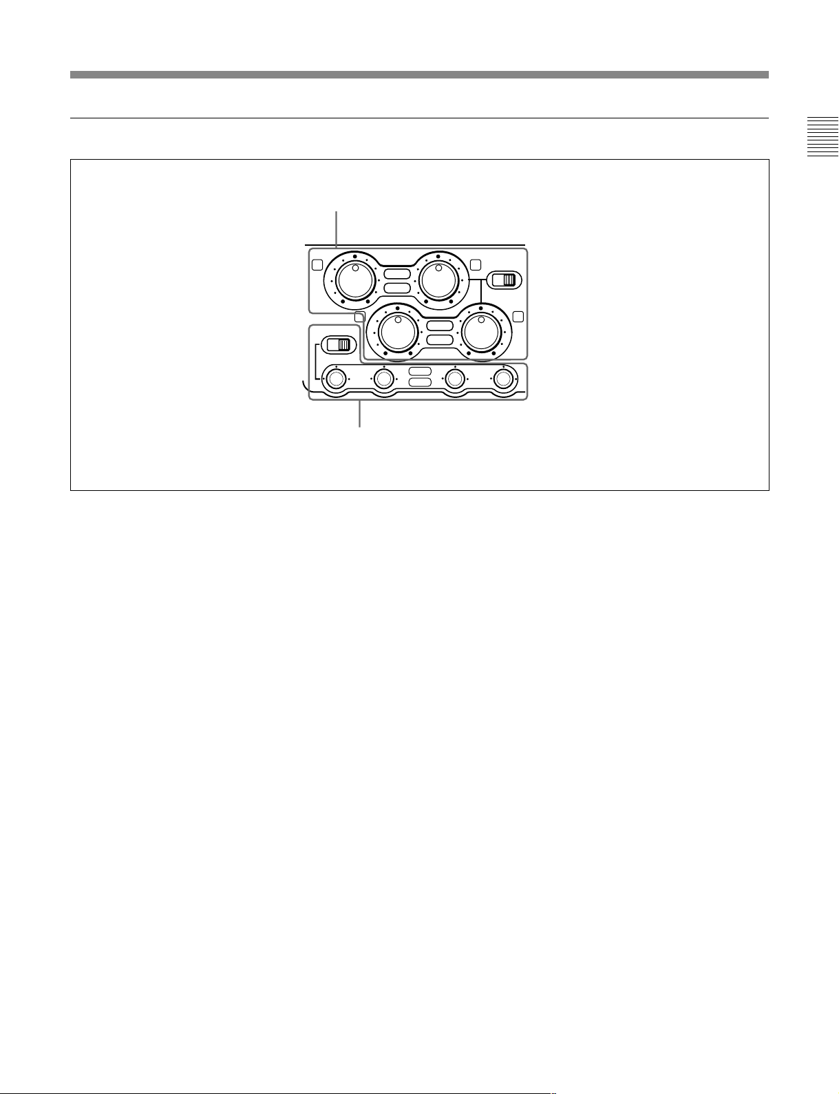
4 Lower Control Panel
1 VIDEO knob and PRE/VAR switch
Chapter 1 Overview
2 CHROMA knob and PRE/VAR switch
3 SET UP/BLACK LEVEL knob and PRE/VAR switch
4 CHROMA PHASE knob and PRE/VAR switch
VIDEO
PRE
VAR
CHROMA TO GENERATOR
PRE
VAR
SET UP/BLACK LEVEL CHROMA PHASE
PRE
VAR
1 VIDEO knob and PRE/VAR (preset/variable)
switch
Adjusts the video signal output level. The function of
the knob changes as follows, depending on the position
of the PRE/VAR switch.
PRE: This is the normal setting. Regardless of the
knob position, the video signal output level is set
to the standard value.
VAR: The video signal output level can be adjusted
across a range of ±3 dB.
You can change the adjustment range by using setup menu
item 714. For details, see page 6-18.
PRE
LOCAL
INT
PRESET
F-RUN
VAR
REMOTE
EXT
REGEN
R-RUNPBPB/EE
9 PB/EE switch
8 F-RUN/R-RUN switch
7 PRESET/REGEN switch
6 INT/EXT switch
5 LOCAL/REMOTE switch
3 SET UP/BLACK LEVEL knob and PRE/VAR
(preset/variable) switch
Adjusts the setup level (in 525/60 mode) and the black
level (in 625/50 mode). The function of the knob
changes as follows, depending on the position of the
PRE/VAR switch.
PRE: This is the normal setting. Regardless of the
knob position, the setup level is set to the standard
value.
VAR: The setup level can be adjusted across a range
of ±30 IRE (in 525/60 mode) and the black level
can be adjusted across a range of ±210 mV (in
625/50 mode).
2 CHROMA knob and PRE/VAR (preset/
variable) switch
Adjusts the chroma signal output level. The function of
the knob changes as follows, depending on the position
of the PRE/VAR switch.
PRE: This is the normal setting. Regardless of the
knob position, the chroma signal output level is
set to the standard value.
VAR: The chroma signal output level can be adjusted
across a range of ±3 dB.
You can change the adjustment range by using setup menu
item 714. For details, see page 6-18.
4 CHROMA PHASE knob and PRE/VAR (preset/
variable) switch
Adjusts the chroma phase (phase relative to burst). The
function of the knob changes as follows, depending on
the position of the PRE/VAR switch.
PRE: This is the normal setting. Regardless of the
knob position, the chroma phase is set to the
standard value.
VAR: The chroma phase can be adjusted across a
range of ±30°.
Chapter 1 Overview 1-9

Locations and Functions of Parts
Chapter 1 Overview
5 LOCAL/REMOTE switch
Selects the source for control of this unit. When two
DNW-A28/A28P units are connected, set this switch
on the playback-side VTR to REMOTE.
LOCAL: This unit is controlled from the control
panel. Normally set the switch to this position.
REMOTE: This unit is controlled from the device
connected to the REMOTE connector. In this
case, all VTR operations using this unit’s control
panel are disabled except the STOP and EJECT
buttons.
When the REMOTE is selected, you can determine which
tape transport control buttons on the control panel are
enabled. See setup menu item 006 on page 6-2.
6 INT/EXT (internal/external timecode) switch
Selects the timecode to use.
INT: Use the timecode generated by this unit’s built-
in timecode generator.
EXT: Use external timecode. When the VITC/LTC/
AUTO item of the submenu is set to LTC or
AUTO, the external timecode input to the TC IN
connector. When it is set to VITC, the VITC of
input video signal.
For more information about the VITC/LTC/AUTO settings,
see page 2-17.
7 PRESET/REGEN (regenerate) switch
Selects the value set in the internal timecode generator.
PRESET: Preset the initial value of the timecode
generated by the internal timecode generator,
either by a control panel operation or by remote
control from the device connected to the
REMOTE connector.
REGEN: Synchronize the internal timecode
generator with the timecode read by the internal
timecode reader.
8 F-RUN/R-RUN (free-run, rec-run) switch
Selects the progression method for the timecode
generated by the internal timecode generator.
F-RUN: Timecode progresses continuously from the
time when this unit is powered on, regardless of
the unit’s operating status.
R-RUN: Timecode progresses only during recording.
When you use this switch, set the INT/EXT switch 6
to INT, and set the PRESET/REGEN switch 7 to
PRESET.
9 PB (playback)/EE switch
Selects the output signals from the VIDEO and
AUDIO OUTPUT connectors during fast forward,
rewind, stop, and standby mode.
PB: Playback (PB) mode
PB/EE: E-E mode
1-10 Chapter 1 Overview
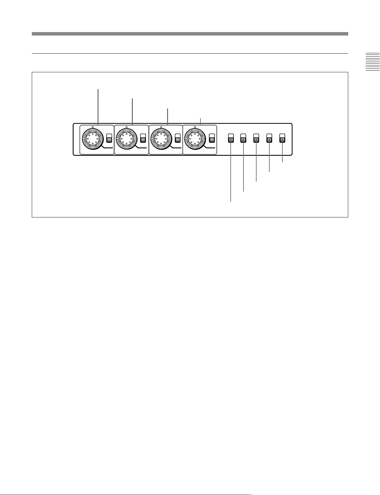
5 Audio control section
1 REC/PB audio level main adjustment knobs
and PRE/VAR switches
21
REC
PB
PRE VAR
Chapter 1 Overview
3
PRE VAR
1 3 4
2
2 REC/PB audio level subadjustment
knobs and PRE/VAR switches
1 REC/PB audio level main adjustment knobs and
PRE/VAR switches
Make level adjustments by channel for playback audio
channels 1 to 4.
The function of the knobs changes as follows,
depending on the position of the PRE/VAR switch.
PRE: Preset to fixed levels. Levels cannot be
adjusted with the level adjustment knobs.
VAR: Levels adjustable with level adjustment knobs.
This allows you to adjust the levels while viewing
the audio level meters in E-E mode.
4
REC
PB
REC
PB
2 REC/PB audio level subadjustment knobs and
PRE/VAR switches
Make level adjustments by channel for audio input to
this unit.
The function of the knobs changes as follows,
depending on the position of the PRE/VAR switch.
PRE: Preset to fixed levels. Levels cannot be
adjusted with the level adjustment sliders.
VAR: Levels adjustable with the level adjustment
sliders. This allows you to adjust the levels while
viewing the audio level meter.
For more information about switching to E-E mode, see the
descriptions of the SEQ/REC and EDIT buttons (page 1-8)
In the factory default configuration, the playback level
is adjusted. But you can also switch the function of
these knobs with the REC/PB audio level
subadjustment knobs 2, by using the MAIN VR
setting in the submenu (see page 2-20).
In the factory default configuration, the recording level
is adjusted. But you can also switch the function of
these knobs with the REC/PB audio level main
adjustment knobs 1, by using the MAIN VR setting
in the submenu (see page 2-20).
Chapter 1 Overview 1-11
Chapter 1 Overview
Locations and Functions of Parts
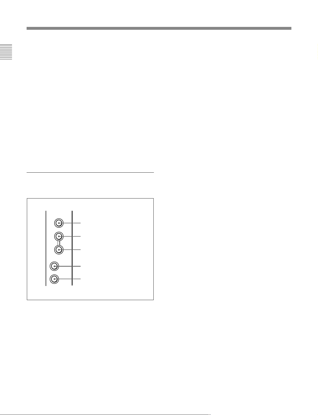
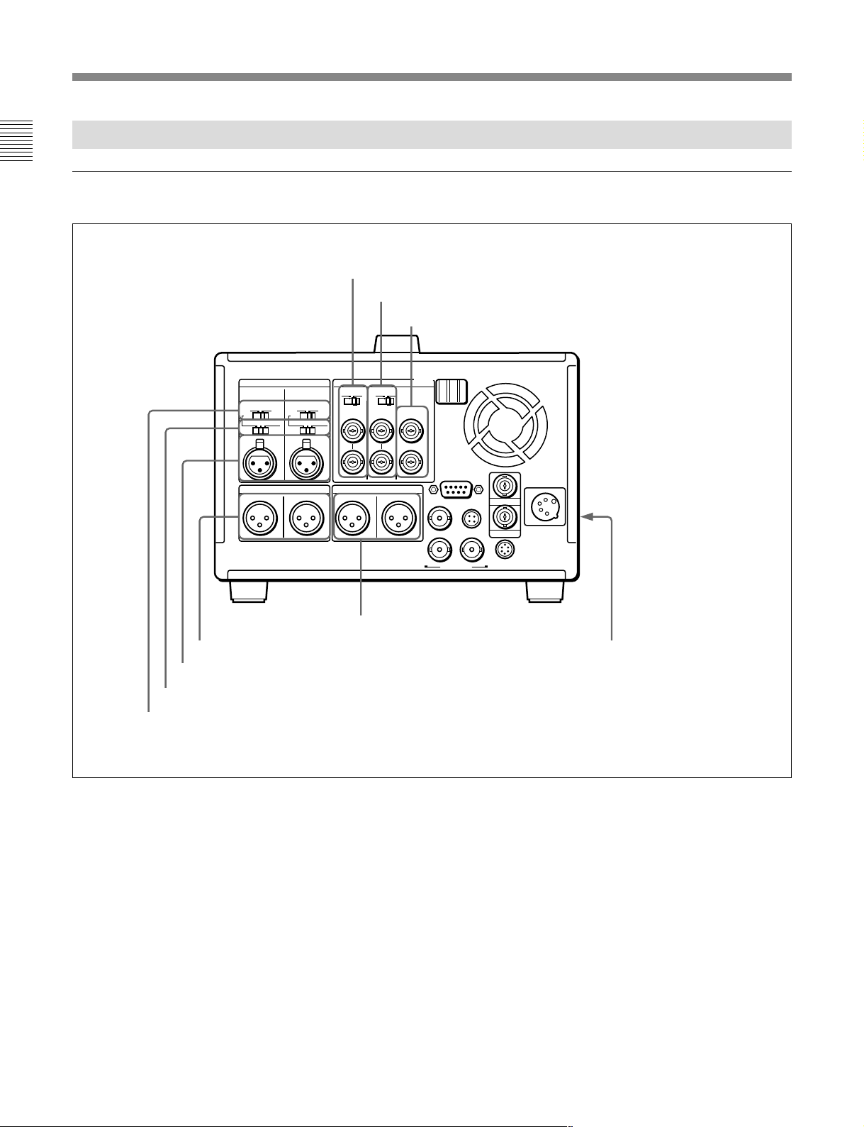
1-3-2 Rear Panel
Analog audio/video input and output section
6 REF. VIDEO IN connectors and 75 Ω termination switch
7 VIDEO INPUT connectors and 75 Ω termination switch
8 VIDEO OUTPUT connectors
AUDIO INPUT
OFF ON
48V
-60 0 +4dBu
CH-1 CH-2
AUDIO OUTPUT MONITOR OUTPUT
1/3 2/4 R L
OFF ON
48V
-60 0 +4dBu
75W 75W
4 AUDIO OUTPUT CH-1/3 and CH-2/4 connectors
3 AUDIO INPUT CH-1/CH-2 connectors
2 AUDIO INPUT CH-1/CH-2 level switches
1 Phantom power supply switches
VIDEO
OFF ON OFF ON
REF.IN INPUT OUTPUT
1
2(SUPER)
REMOTE
DC OUT
SDI IN
12
SDI OUT AUX
TC IN
TC OUT
5 MONITOR OUTPUT L/R connectors
DC IN
Battery adaptor attachment
screws
1 Phantom power supply switches
When the AUDIO INPUT CH-1/CH-2 level switches
2 are set to –60 dBu, phantom power is supplied to
the AUDIO INPUT connectors when these switches
are set to ON.
1-12 Chapter 1 Overview
2 AUDIO INPUT CH-1/CH-2 level switches
Select the input level of the analog audio signals of
input channels 1 and 2.
–60 dBu: Microphone input
0 dBu: Line audio input
+4 dBu: Line audio input
(0 dBu = 0.775 Vrms)

3 AUDIO INPUT CH-1/CH-2 connectors (XLR 3pin, female)
Input the analog audio signals of input channels 1 and
2.
4 AUDIO OUTPUT CH-1/3 and CH-2/4
connectors (XLR 3-pin, male)
Output the audio signals of the channels selected with
the LINE OUT in the submenu. You can select two
combinations of output signals: channels 1 and 2, or
channels 3 and 4.
For more information about LINE OUT settings, see page 2-
21.
Note
The level can be adjusted from the control panel, but
mixed signals cannot be output.
5 MONITOR OUTPUT L/R connectors (XLR 3pin, male)
Output the audio signals of the channels selected with
the MONITOR L/R in the submenu. The level is
adjustable, and mixing is possible. Connect these
connectors when you want to output mixed signals.
For more information about MONITOR L/R settings, see
page
2-21.
6 REF. VIDEO IN (reference video signal input)
connectors (BNC type) and 75 Ω termination switch
Input a video signal with color burst (VBS) or
monochrome video signal (VS) as reference video
signal. Set the 75 Ω termination switch to OFF when
the signal is bridged, and to ON when the signal is not
bridged.
7 VIDEO INPUT (analog composite video input)
connectors (BNC type) and 75 Ω termination switch
Input an analog composite video signal. Set the 75 Ω
termination switch to OFF when the signal is bridged,
and to ON when the signal is not bridged.
8 VIDEO OUTPUT (analog composite video
output) connectors (BNC type)
Output analog composite video signals. You can
superimpose timecode, menu settings, error messages,
or other information on the output of the 2(SUPER)
connector. (The superimposed information varies
depending on the setting of the SUPER in the
submenu.)
For more information about SUPER settings, see page 2-24.
For details about the superimposed information, see page 2-
9.
Chapter 1 Overview
You can also adjust the output level of the LEVEL knob with
the MONITOR in the submenu. For details, see page 2-21.
Chapter 1 Overview 1-13
Chapter 1 Overview
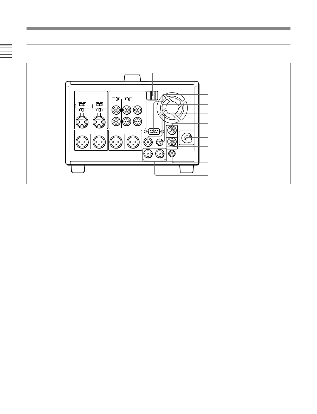
Locations and Functions of Parts
Digital signal/timecode/remote control/power input and output section
Cable clamps
AUDIO INPUT
OFF ON
48V
-60 0 +4dBu
CH-1 CH-2
1/3 2/4 R L
OFF ON
48V
-60 0 +4dBu
AUDIO OUTPUT MONITOR OUTPUT
VIDEO
OFF ON OFF ON
75W 75W
REF.IN INPUT OUTPUT
1
2(SUPER)
SDI IN
12
1 REMOTE (9-pin remote control) connector (DSUB 9-pin)
When editing with two DNW-A28/A28P units,
connect this connector on each unit using a 9-pin
remote control cable (not supplied). When editing with
this unit and D-1, D-2, Betacam VTR, Digital Betacam
VTR or other external equipment, connect the external
equipment.
2 SDI IN (serial digital interface input) connector
(BNC type)
Input a D-1 format video/audio signal. When editing
with two DNW-A28/A28P units, connect the SDI
OUT connector 8 on the player unit with this
connector on the recorder unit.
3 DC OUT connector
This connector supplies power to the BVR-3 Remote
Control Unit.
4 TC IN (timecode input) connector (BNC type)
To record timecode from an external device, input the
timecode from the external device’s timecode output
connector.
1 REMOTE connector
2 SDI IN connector
3 DC OUT connector
REMOTE
TC IN
DC OUT
TC OUT
SDI OUT AUX
DC IN
4 TC IN connector
5 DC IN connector
6 TC OUT connector
7 AUX connector
8 SDI OUT connectors
5 DC IN (external power input) connector (XLR
4-pin, male)
When using the BKP-L551 Battery Adaptor to mount
a battery or the AC-DN2A adaptor on the side of this
unit, connect the power cable of the BKP-L551. When
using the AC-550/550CE AC Adaptor, connect to the
DC output connector of the AC-550/550CE. You can
also use the DC-210 Battery Adaptor to connect a BP90(A) Battery Pack.
For more information, see section 2-1 “Power
Preparations”.
6 TC OUT (timecode output) connector (BNC
type)
Outputs the following types of timecode, depending on
the VTR operating status.
During playback: The playback timecode
During recording: The timecode generated by the
internal timecode generator, or the timecode input
through the TC IN connector.
7 AUX (auxiliary) connector
This connector is used only for service.
1-14 Chapter 1 Overview
8 SDI OUT (serial digital interface output)
connectors (BNC type)
Output a D-1 format video/audio signal. The same
signals are output from the left and right connectors.
2-1 Power Preparations
Chapter 2 Preparations
This unit can be powered by batteries or AC power.
Note
If you attach or remove batteries or AC adaptors
incorrectly, they may fall down and cause body injury.
Follow the procedures described below to attach or
remove them.
2-1-1 Usable Batteries
Batteries that can be used with this unit are as follows.
For each type of battery, a special battery adaptor and
battery charger is required.
Battery
BP-90(A)
(mounted on this
unit)
BP-90(A)
(connected to DC
IN connector)
BP-L60(A)/L90(A) BKP-L551
Battery Adaptor Battery Charger
DC-L90
DC-210 BC-210/210CE/410/
BC-210/210CE/410/
410CE
410CE
BC-L100/
L100CE/L50
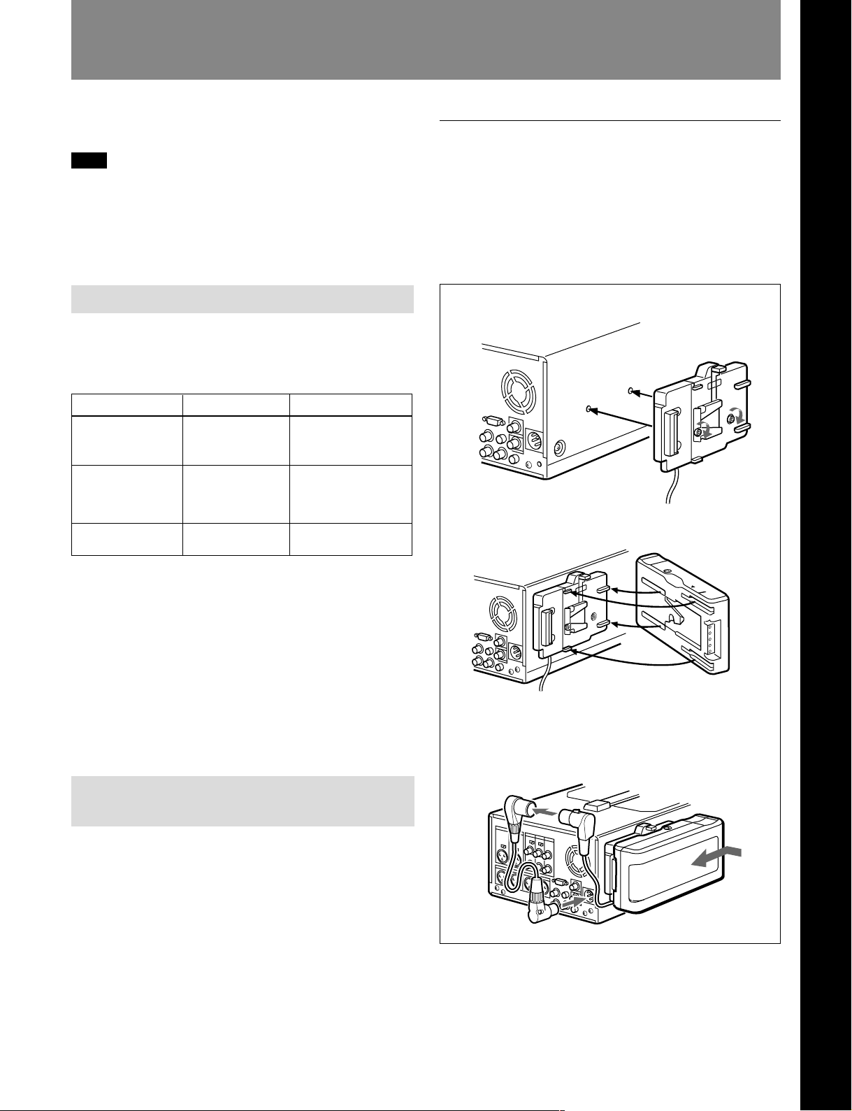
To attach the battery pack
Attach the BP-L60(A)/L90(A) as shown in the figure
below. Before attaching, remove the two screws on the
side panel of this unit.
For details on attaching the BKP-L551, refer to the BKPL551 installation manual.
1 Screw the BKP-L551 on the side panel.
2 Align the groove on the top panel of the BP-L60(A)/
L90(A) with the guides.
Chapter 2 Preparations
Notes about battery usage
•Before using the batteries, be sure to charge them
fully with the special battery charger. Refer to the
operating instructions of your battery charger for
more information about how to charge the batteries.
•Batteries may not be completely charged if you
charge them immediately after use when they are still
warm. You should wait until the batteries cool before
charging them.
2-1-2 Using the BP-L60(A)/L90(A) Battery Pack
This unit can be operated for about 80 minutes at
normal temperature on fully charged BP-L90 Battery
Pack.
To charge the battery pack
Before use, charge the battery pack with the BC-L100/
L100CE Battery Charger. It takes about 2.5 hours to
charge the BP-L60(A) and about 3.5 hours to charge
the BP-L90(A).
3 Slide the BP-L60(A)/L90(A) in so that its connector is
firmly connected to the battery connector. Use the
optional extension cable (part No. 1-790-446-11) to
connect the DC cable of the BKP-L551 to the DC IN
connecteor on this unit.
For more information about how to charge the battery pack,
refer to the manual for the BC-L100/L100CE.
Chapter 2 Preparations 2-1
Power Preparations
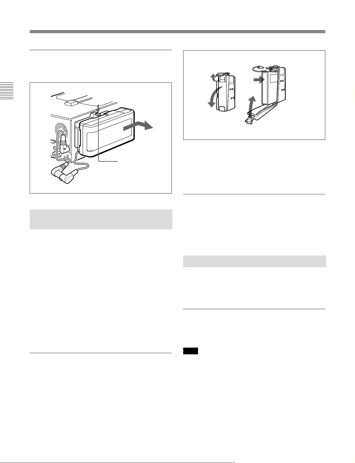
To remove the battery pack
With the lever pushed in, slide the BP-L60(A)/L90(A)
out.
Chapter 2 Preparations
2-1-3 Using the BP-90(A) Battery Pack
Different battery adaptors are used when attaching the
BP-90(A) on the side panel of this unit and when
connecting it the DC IN connector.
This unit can be operated for about 60 minutes at
normal temperature on a fully charged BP-90(A)
Battery Pack.
To charge the battery pack
Before use, be sure to charge the battery pack with the
BC-210/210CE/410/410CE Battery Charger. It takes
about 2 hours to charge the BP-90(A).
BP-L60(A)/L90(A)
Lever
3 Insert the BP-90(A).
4 Push the plug in.
1 Lift the lever up.
2 Open the side
cover.
5 Close the side cover
and pull the lever
down.
2 Attach the DC-L90 to the side panel of this unit.
Use the same method that you use to attach the BPL60(A)/L90(A). For details, refer to “To attach the
battery pack” on page 2-1.
To connect to the DC IN connector
Use the DC-210 Battery Adaptor.
For more information about connections, refer to the
operating instructions of the DC-210.
2-1-4 Using AC Power
You can operate the unit from an AC power source by
using the AC-550/550CE AC Adaptor or AC-DN2A
AC Adaptor.
To use the AC-550/550CE
For more information about how to charge the battery pack,
refer to the manual for the BC-210/210CE/410/410CE.
To attach to side this unit
Use the DC-L90 Battery Adaptor.
1 Mount the BP-90(A) in the DC-L90.
2-2 Chapter 2 Preparations
As shown in the figure on next page, connect the AC550/550CE to the AC power source and turn it on.
Note
Noise may occur in video and audio signals at the
moment when the unit switches from the battery pack
to AC power.
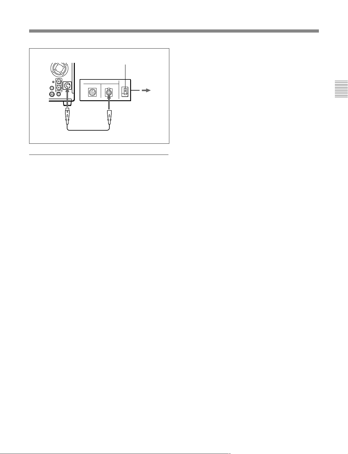
POWER switch: ON
AC-550/550CE
AC power cord
(supplied with
AC-550/550CE)
To AC power
DC IN
DC power cord (supplied with AC-550/550CE)
DC OUT
To use the AC-DN2A
Attach the AC-DN2A on the side panel of this unit,
and connect to AC power.
Use the same method that you use to attach the BP-L60 (A)/
L90 (A). For details, refer to “To attach the battery pack”
on page 2-1.
Chapter 2 Preparations
Chapter 2 Preparations 2-3
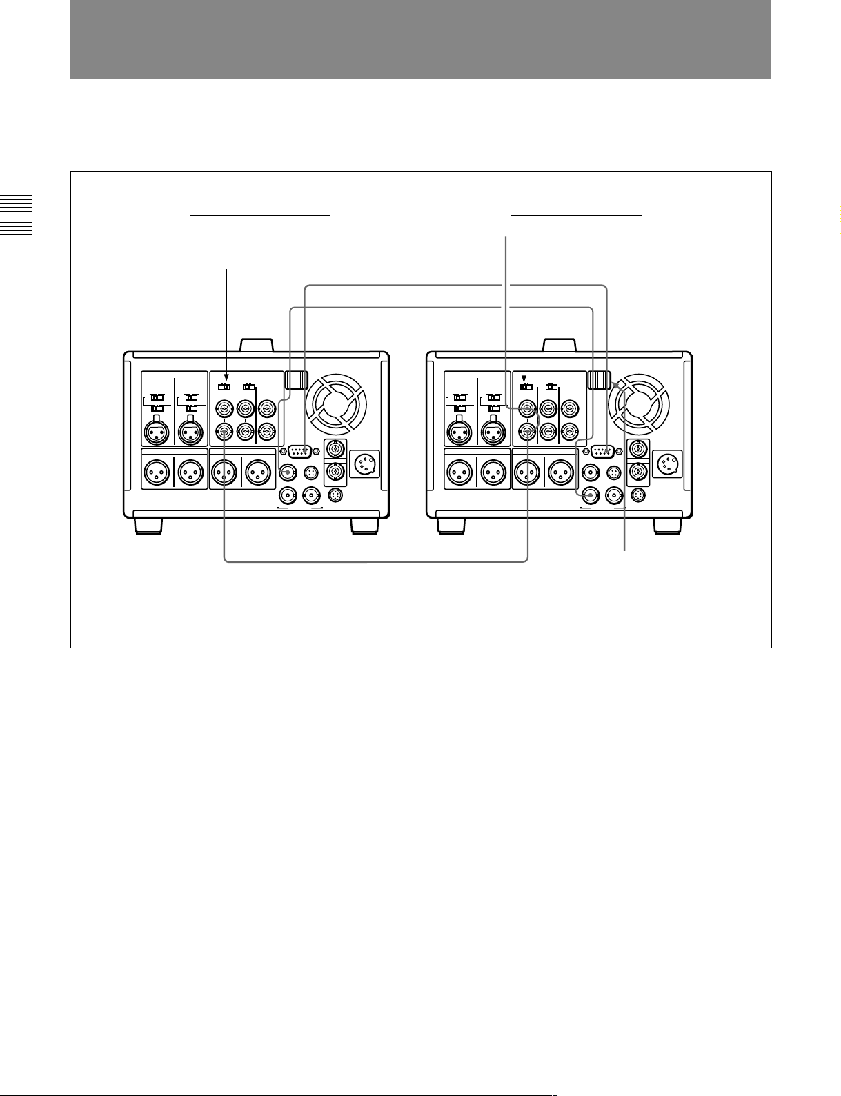
2-2 Connection
The figure below shows how to connect two DNWA28/A28P units for editing.
Chapter 2 Preparations
Recording-side VTR Playback-side VTR
Reference video signal
c)
REF. VIDEO 75Ω termination switch: ON
a)
b)
REF. VIDEO 75Ω termination switch: OFF
SDI IN
REMOTE
REF. VIDEO IN
c)
a) 9-pin remote control cable (not supplied)
b) 75 Ω coaxial cable with BNC plugs (not supplied)
c) To input a reference video signal, connect a 75 Ω coaxial cable with BNC plugs (not
supplied) and set the REF. VIDEO 75Ω termination switches as shown in the figure.
SDI OUT 1
REMOTE
REF. VIDEO IN
Push cables a) and b) in the cable clamps.
2-4 Chapter 2 Preparations
2-3 Handling Cassettes
To record with this unit, you can use half-inch width
Betacam SX S cassettes, Betacam SP S cassettes
(metal tape), or UVW S cassettes (metal tape).
The number in the model name of the cassette
indicates the cassette’s normal recording time in
minutes (for example, 12 minutes in the case of the
BCT-12SX). However, when you are using Betacam
SP S cassettes and S cassettes for UVW VTRs on this
unit, you can record up to twice the amount of time
indicated on the cassette (see the table below).
Usable Cassettes
Betacam SX
Betacam SP (metal tape)
UVW (metal tape)
Notes
•Digital Betacam cassettes cannot be used.
•Oxide tapes recorded in the Betacam format and
metal tapes recorded in the Betacam SP format can
be only played back.
BCT-6SX/12SX/22SX/32SX/
60SX
BCT-5MA/10MA/20MA/30MA
(Recording time: 10/20/40/60
minutes)
UVWT-10MA/20MA/30MA
(Recording time: 20/40/60
minutes)
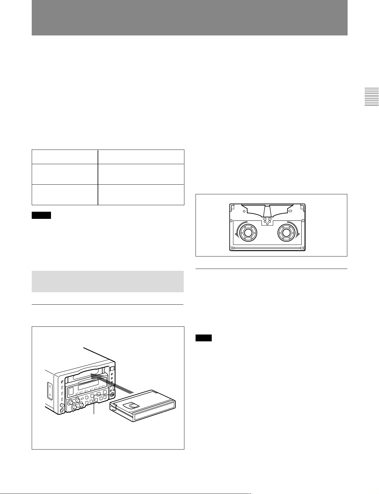
2 Load a cassette in the direction shown in the figure
after checking the following points.
•That “ERROR-10” is not displayed in the FL
display panel.
•That there is no slack in the tape.
If “ERROR-10” appears in the FL display panel
This means that there is condensation inside the unit.
For the steps to take in this case, see “Moisture
Condensation” (page A-3).
If there is slack in the tape
Take up the slack by rotating the reels in the directions
shown by the arrows in the figure, keeping one reel
fixed by pressing it with your finger as you rotate the
other reel.
The reels stop rotating when there is no more slack.
Chapter 2 Preparations
2-3-1 Loading/Ejecting Cassettes
To load a cassette
1
To eject the cassette
1 With the unit powered on, press the EJECT button.
A part of the cassette comes out from the unit.
2 Take out the cassette.
Note
The EJECT cannot be used to eject a cassette when
battery power falls to below about 9 V. Remove the
cassette manually (see next page).
2
1 Set the POWER switch to ON.
Chapter 2 Preparations 2-5
Handling Cassettes
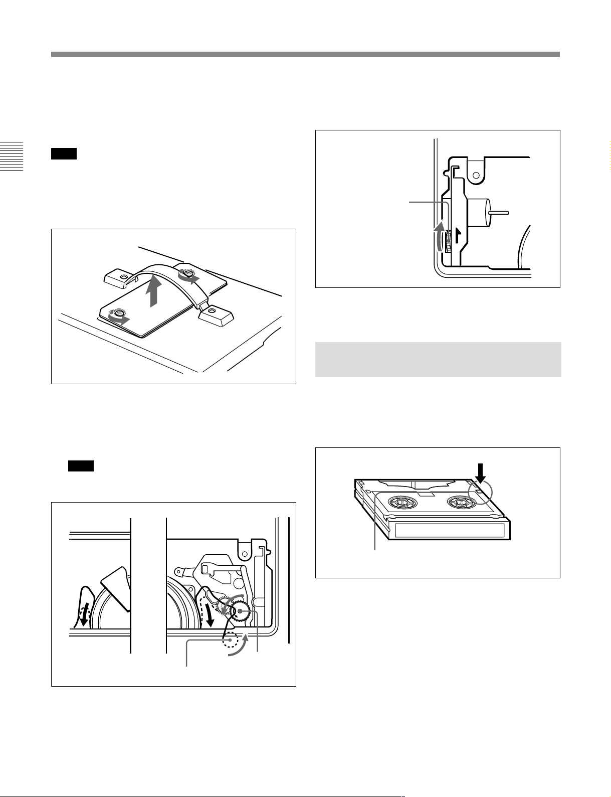
If there is no choice but to remove the
cassette manually
Remove the cassette manually when battery power
falls to below about 9 V.
Note
Chapter 2 Preparations
Power the unit off before removing the cassette
manually. If the unit is powered, the drums may rotate
and cause body injury.
1 Remove the cover on the center of the top panel.
3 Check that all tape has be wound into the cassette,
and eject the cassette by rotating the manual eject
gear in the direction shown by the arrow.
Manual eject gear
4 Attach the cover to the top panel.
2-3-2 Preventing Accidental Erasures
2 Press the manual eject knob (the red knob). Take
up any slack in the tape by rotating the black gears
on the top of the capstan in the counterclockwise
direction.
Note
Perform the operation carefully so that edges of
internal parts will not injure your hand.
Manual eject
Black gear
knob
To make it impossible to accidentally erase or record
over the contents of a cassette, press in the erasure
prevention plug. Return the plug to its original position
when you want to record on the cassette again.
Cassette
Erasure prevention plug
\
2-6 Chapter 2 Preparations

2-4 Setting Reference Video Signals
This section explains how reference video signals for
synchronization of video output and servo lock are
selected according to settings made with this unit.
Reference video signal for video output
Output video signals are synchronized with the signal
generated by this unit’s internal reference video signal
generator. The internal reference video signal
generator can be synchronized with an external
reference video signal or with an input video signal
(SDI or composite video).
Setting Setting of setup menu item
Operating mode of this unit Recording
309
OUT REF setting “REF”“INPUT”
a)
Editing
Other Ref
b)
Reference video signal for servo lock
synchronization
Servo lock can be synchronized with an external
reference video signal, with an input video signal (SDI
or composite video), or with the signal generated by
this unit’s internal reference video signal generator.
As shown in the table below, a signal for
synchronization of the internal reference video signal
generator and a reference video signal for
synchronization of servo lock are selected according to
the setting of setup menu item 309, the setting of the
OUT REF in the submenu, and the operating mode of
the unit.
For more information about setup menu item 309, see page
6-11. For more information about the OUT REF, see page
2-22.
“AUTO (AUTO1/AUTO2)”
d)
Input
See below, “Reference video
signals in editing”
Input
“EXT”
–
Ref
Chapter 2 Preparations
c)
a) During recording to tape.
b) When the assemble editing or insert editing mode has
been selected.
c) Synchronize with external reference video signal (input
to the REF. VIDEO IN connector).
Reference video signals in editing
When the OUT REF is set to REF, the signal shown in
the table below is selected, depending on whether
setup menu item 309 is set to AUTO1 or AUTO2.
Note
Normally select AUTO1 and synchronize the external
reference video signal with the input video signal.
Select AUTO2 when the external reference video
signal is not synchronized with the input video signal.
Setting of setup menu item 309 AUTO1
Synchronization signal for internal reference video
signal generator
Synchronization signal for servo reference
video signal
External reference video signal Input video signal
Input video signal
d) Synchronize with input video signal (SDI or composite
video), as selected with “source video signal” in the
submenu (see page 2-17).
If you select AUTO1 under these conditions, noise
may enter the video and audio signals, making editing
difficult.
AUTO2
Chapter 2 Preparations 2-7

Setting Reference Video Signals
When the signal selected in the menu is not being input
The servo reference video signal and internal reference
signal generator synchronize as follows.
When “Input” is selected for the sync signal
Chapter 2 Preparations
(see note d) of the table on previous page)
When a video signal is not being input, synchronize
with an external reference video signal.
When “Ref” is selected for the sync signal
(see note c) of the table on previous page)
When an external reference video signal is not being
input, there is no external synchronization. The servo
reference video signal synchronizes with the output of
the internal reference video signal generator.
2-8 Chapter 2 Preparations
2-5 Information Displayed on the Monitor
The monitor connected to the VIDEO OUTPUT
connector 2 (SUPER) displays setup menus, error
messages, time data, and information about the unit’s
operating status.
To display superimposed text information
To display superimposed time data and text
information about the operating status of the unit, set
the SUPER in the submenu to ALL (see page 2-23).
To adjust the displayed text
You can adjust the position, size, and type of
superimposed information using setup menu items
002, 003, 009, and 011.
For details, see pages 6-1 and 6-2.
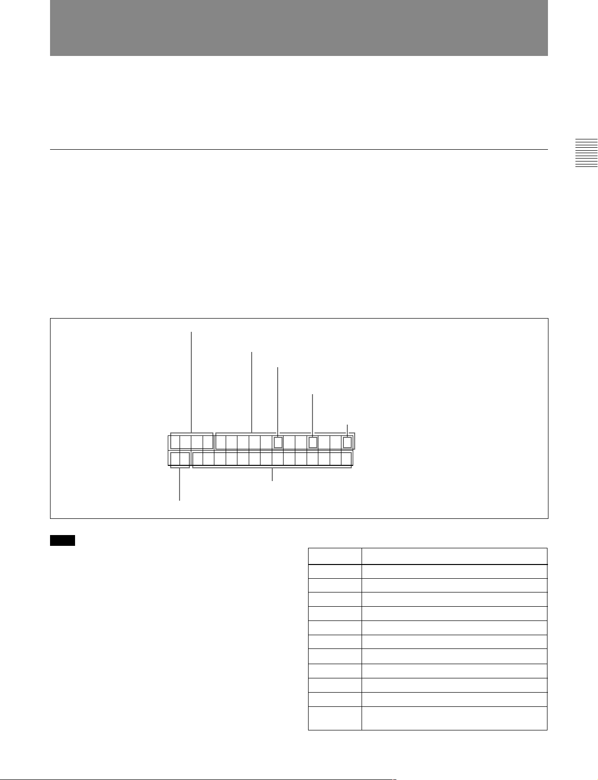
1 Time data type
Time data
2 Timecode reader drop-frame mark (525 mode)
For more information about the setup menus, see chapter 6
“Setup Menu”.
Chapter 2 Preparations
The figure below shows the time data and operation
status that can be superimposed.
TCR. 23 : 59 . 40 . 18*
PSHUTTLESTILL
6 Operating mode
5 Recorder/player selection
Note
The example above shows the factory default
configuration.
You can use setup menu item 005 to display a different
type of time data in the second line as well.
For details, see page 6-2.
3 Timecode generator drop-frame mark
(525 mode)
4 VITC data field mark
1 Time data type
Display Meaning
CTL CTL counter data
TCR LTC reader timecode data
UBR LTC reader user bits data
TCR. VITC reader timecode data
UBR. VITC reader user bits data
TCG Timecode generator timecode data
UBG Timecode generator user bits data
a)
IN
a)
OUT
a)
AI
a)
DUR
a) Displayed when this unit is used with an editor.
IN point time data
OUT point time data
AUDIO IN point time data
The duration between any two of the three
edit points (IN, OUT, AUDIO IN)
Chapter 2 Preparations 2-9
Information Displayed on the Monitor
Note
Asterisks are displayed in this block when timecode or
user bits could not be read correctly, for example as
T*R, U*R.
2 Timecode reader drop-frame mark (525 mode)
Chapter 2 Preparations
[.] (period): Indicates drop-frame mode.
[:] (colon): Indicates non-drop frame mode.
3 Timecode generator drop-frame mark (525
mode)
[.] (period): Indicates drop-frame mode (factory
default).
[:] (colon): Indicates non-drop frame mode.
4 VITC data field mark
[ ] (blank): Display of fields 1 and 3
[*] (asterisk): Display of fields 2 and 4
5 Recorder/player selection
The indication changes depending on whether this unit
is the recording-side VTR or the playback-side VTR.
No display: Neither of them
P: Playback-side VTR
R: Recording-side VTR
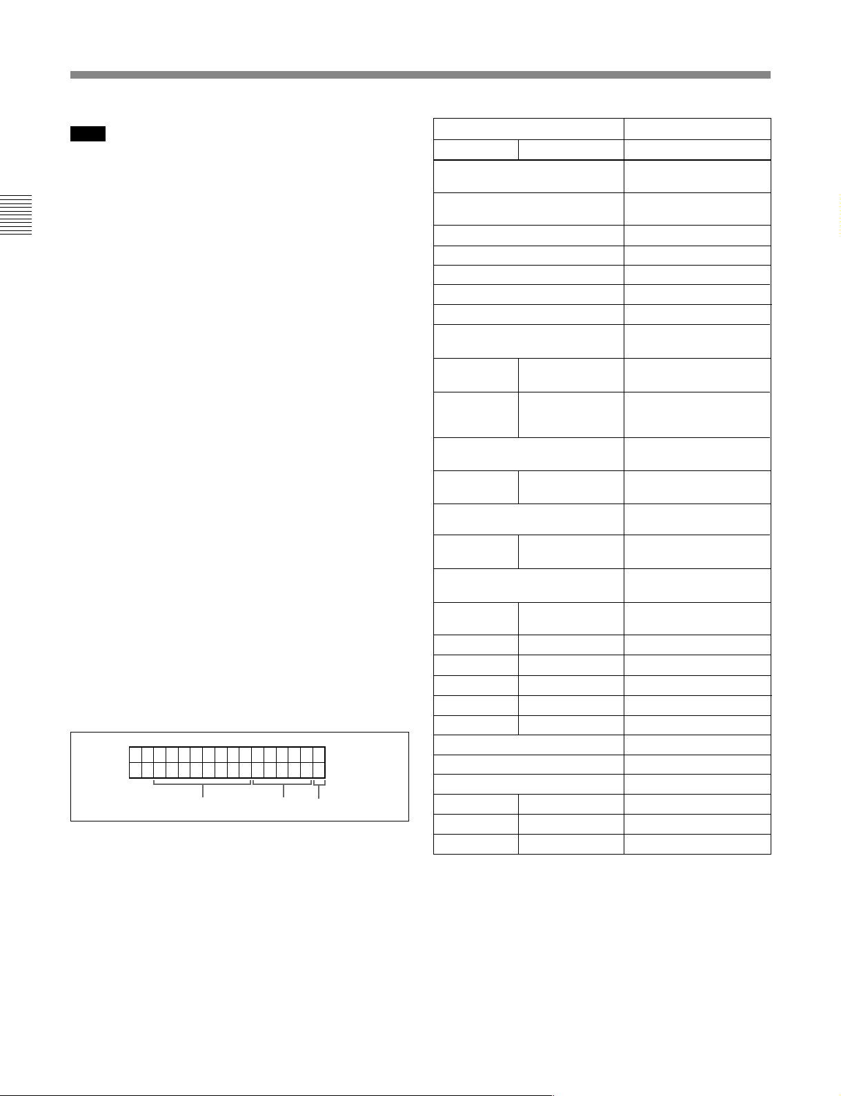
6 Operating mode
The display is divided into blocks A, B, and C, shown
in the figure below.
Block A: Operating mode
Block B: Servo lock status or tape speed
Block C: The p mark, indicating an auto editing
segment
The contents displayed in each block are listed on next
page.
ABC
Display Operating Mode
Block A
TAPE
UNTHREAD
STANDBY
OFF
T. RELEASE Tension release mode
STOP Stop mode
F. FWD Fast forward mode
REW Rewind mode
PREROLL
PLAY
PLAY
PLAY % difference with
REC Recording mode (servo
REC
SEQ REC
SEQ REC Sequential recording
EDIT Editing mode (servo
EDIT
JOG
JOG
JOG
SHUTTLE
a)
VAR
PREVIEW
AUTO EDIT
REVIEW
D-PREV
a)
D-EDIT
DMC-SPD
Block B
No cassette loaded
Standby off mode
Preroll mode
Playback mode (servo
unlock)
LOCK Playback mode (servo
respect to normal
speed
LOCK
LOCK
LOCK
STILL
FWD
REV
(speed)
(speed)
a)
a)
a)
a)
(speed)
(speed)
a)
(speed)
b)
b)
lock)
Capstan override mode
unlock)
Recording mode (servo
lock)
Sequential recording
mode (servo unlock)
mode (servo lock)
unlock)
Editing mode (servo
lock)
Jog mode still picture
Forward jog
Reverse jog
Shuttle mode
Variable mode
Preview mode
Auto edit mode
Review mode
DMC edit preview mode
DMC edit mode
DMC initial speed setting
a) Displayed when this unit is used with an editor
b) Initial speed or speed stored in memory
2-10 Chapter 2 Preparations
To create new text data
Use Setup Menu items 005 and 017 (pages 6-2 and 6-
3).
1 Set Setup menu item 005 to CHARCTER.
For more information about menu operations, see
Chapter 6 “Setup Menu”.
2 Set Setup menu item 017 to ON.
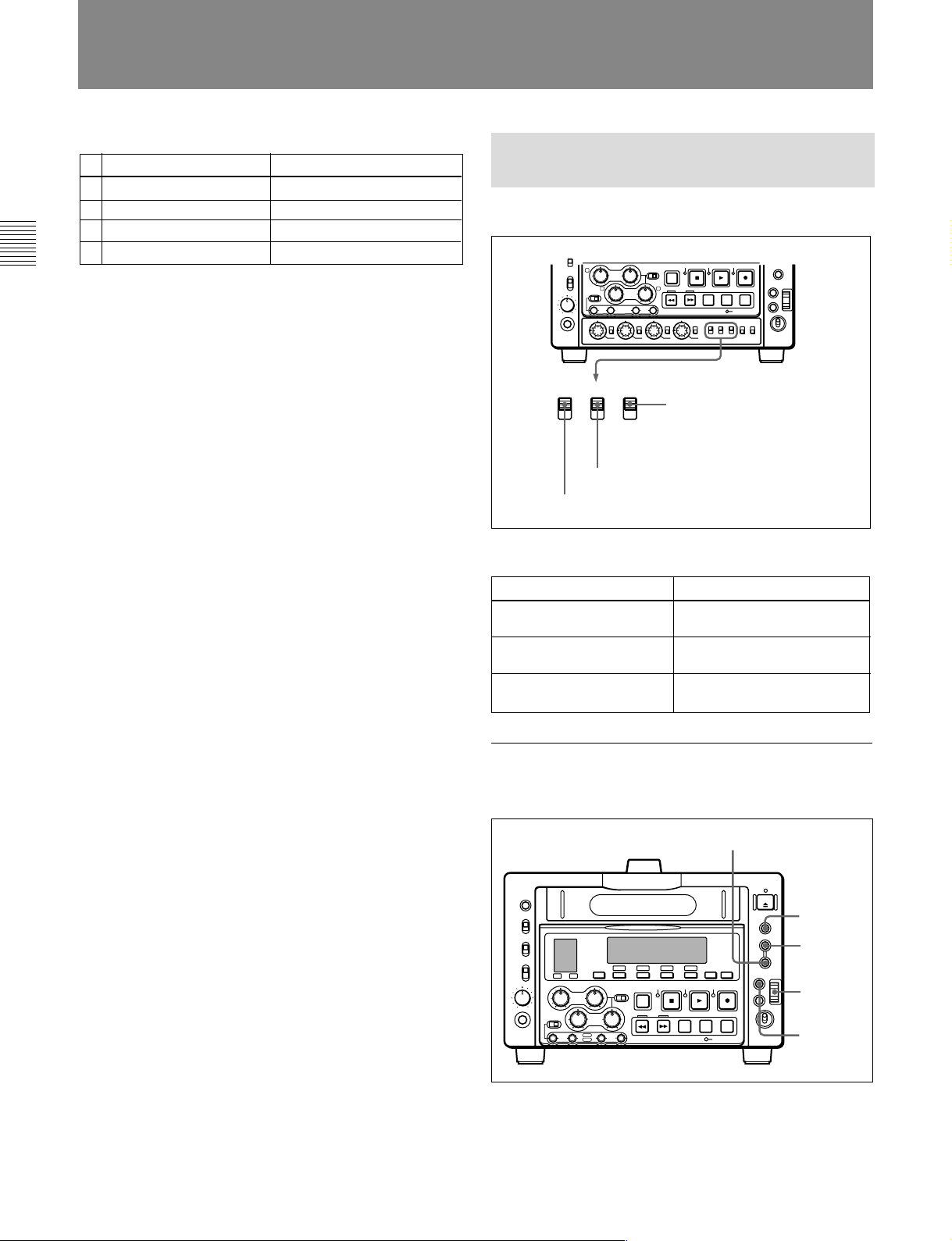
3 Press the SET button.
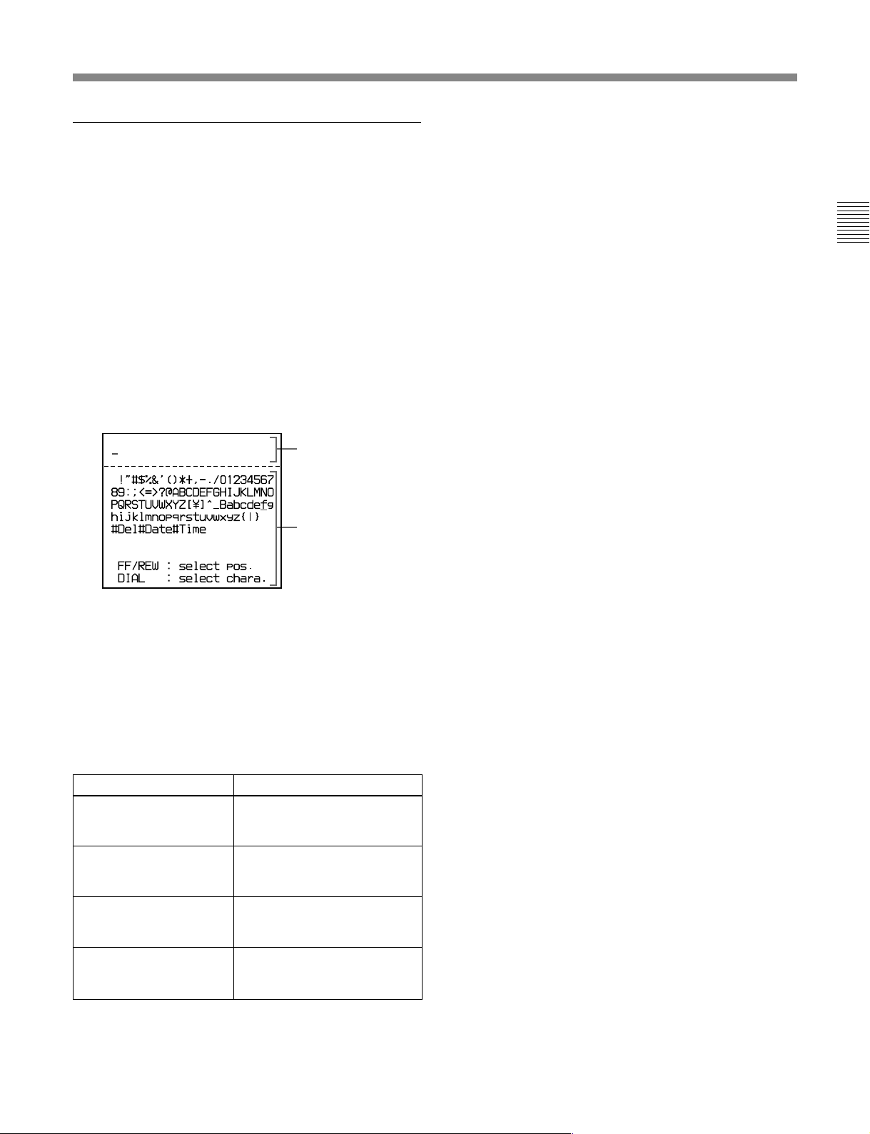
The Text Data Creation Screen appears and the
F FWD button lights.
Data entry section
Character selection
section
To delete a character from the data entry
section: Select #Del in the character selection
section.
To enter the date: Select #Date in the character
selection section.
To enter the time: Select #Time in the character
selection section.
Chapter 2 Preparations
4 Enter the data in the data entry section.
To specify the data entry position: Move the
cursor to the right by pressing the F FWD
button or to the left by pressing the REW
button.
To select a character to enter: Rotate the jog dial
to move the cursor to the desired character, then
press the jog dial.
Operation
Rotate upwards
Rotate downward Moves to the left. When the
Rotate upwards while
pressing the SHIFT button
Rotate downward while
pressing the SHIFT button
Cursor movement
Moves to the right. When the
last character is reached,
moves to the first character.
first character is reached,
moves to the last character.
Moves one line up. When the
cursor is in the top line, moves
to the bottom line.
Moves one line down. When
the cursor is in the bottom line,
moves to the top line.
Chapter 2 Preparations 2-11
2-6 Setting Timecode
There are four ways to record timecode.
INT/EXT switch PRESET/REGEN switch
(1) PRESET
INT
(2)
EXT
(3) INT
(4) PRESET
Chapter 2 Preparations
(1)Record the output of the internal timecode
generator with setting an initial value.
(2) Record the output of the internal timecode
generator, which has been synchronized with an
external timecode generator.
(3)Record the output of the internal timecode
generator, which has been synchronized with
playback timecode. (This method is always used
during editing.)
(4)Record the output of an external timecode generator
without regeneration.
For more information about timecode generator settings,
see the setup menu “Item 600 series: timecode generator
settings” (page 6-14).
For more information about playback timecode settings, see
page 4-4.
In addition to the INT/EXT switch and the PRESET/
REGEN switch, the following settings are made with
submenus.
•VITC ON/OFF: (home page)
•VITC/LTC/AUTO: (home page)
•DF/NDF (525 mode): (general settings page)
PRESET
PRESET
2-6-1 Setting an Initial Value and Recording Timecode
Set the switches and submenu items as shown below.
3
43
PB
INT
PRESET
F-RUN
F-RUN/R-RUN: Either
EXT
REGEN
R-RUN
TC GENERATOR
PRESET/REGEN: PRESET
INT/EXT: INT
Item Setting
VITC ON/OFF (home
page)
VITC/LTC/AUTO (home
page)
DF/NDF (general settings
page)
To set an initial timecode value
position
Submenu settings
Desired setting (ON for
recording)
No setting required (ignored)
Desired setting (in 525 mode)
For more information about submenus, see section 2-7-1
“Displays on the Home Page of the Submenu”.
2-12 Chapter 2 Preparations
Perform the following procedure.
RESET button
1
TC 525 SX-- BATT
00:00:00:00
AU-1 AUTO VITCON SDI
2
3,4,5
6
1 Press the CTL/TC/U-BIT button and select TC.
 Loading...