

Sony Betacam SX DNW-A22, Betacam SX DNW-A22P Operation Manual

DIGITAL VIDEOCASSETTE PLAYER
DNW-A22/A22P
OPERATION MANUAL
1st Edition (Revised 2)
Serial No. 10001 and Higher
[English]
WARNING
To prevent fire or shock hazard, do not
expose the unit to rain or moisture.
To avoid electrical shock, do not open the
cabinet. Refer servicing to qualified
personnel only.
This symbol is intended to alert the user to the
presence of important operating and
maintenance (servicing) instructions in the
literature accompanying the appliance.
For the customers in the USA
This equipment has been tested and found to comply with
the limits for a Class A digital device, pursuant to Part 15 of
the FCC Rules. These limits are designed to provide
reasonable protection against harmful interference when the
equipment is operated in a commercial environment. This
equipment generates, uses, and can radiate radio frequency
energy and, if not installed and used in accordance with the
instruction manual, may cause harmful interference to radio
communications. Operation of this equipment in a
residential area is likely to cause harmful interference in
which case the user will be required to correct the
interference at his own expense.
You are cautioned that any changes or modifications not
expressly approved in this manual could void your authority
to operate this equipment.
Use an appropriate AC power cord meeting the power
requirements of the unit. The unit is supplied with no AC
power cord.
WARNING: THIS WARNING IS APPLICABLE FOR USA
ONLY.
If used in USA, use the UL LISTED power cord
specified below.
DO NOT USE ANY OTHER POWER CORD.
Plug Cap Parallel blade with ground pin
(NEMA 5-15P Configuration)
Cord Type SJT, three 16 or 18 AWG
wires
Length Less than 2.5 m (8 ft 3 in)
Rating Minimum 10 A, 125 V
Using this unit at a voltage other than 120V
may require the use of a different line cord or
attachment plug, or both. To reduce the risk of
fire or electric shock, refer servicing to qualified
service personnel.
For the customers in Europe
This product with the CE marking complies with both the
EMC Directive (89/336/EEC) and the Low Voltage Directive
(73/23/EEC) issued by the Commission of the European
Community.
Compliance with these directives implies conformity to the
following European standards:
• EN60065: Product Safety
• EN55103-1: Electromagnetic Interference (Emission)
• EN55103-2: Electromagnetic Susceptibility (Immunity)
This product is intended for use in the following
Electromagnetic Environment(s):
E1 (residential), E2 (commercial and light industrial), E3
(urban outdoors) and E4 (controlled EMC environment, ex.
TV studio).
The shielded interface cable recommended in this manual
must be used with this equipment in order to comply with the
limits for a digital device pursuant to Subpart B of Part 15 of
FCC Rules.
For the customers in the United Kingdom
WARNING
THIS APPARATUS MUST BE EARTHED
IMPORTANT
The wires in this mains lead are coloured in accordance with
the following code:
Green-and-yellow: Earth
Blue: Neutral
Brown: Live
As the colours of the wires in the mains lead of this
apparatus may not correspond with the coloured markings
identifying the terminals in your plug proceed as follows:
The wire which is coloured green-and-yellow must be
connected to the terminal in the plug which is marked by the
letter E or by the safety earth symbol Y or coloured green
or green-and-yellow.
The wire which is coloured blue must be connected to the
terminal which is marked with the letter N or coloured black.
The wire which is coloured brown must be connected to the
terminal which is marked with the letter L or coloured red.

Table of Contents
Chapter 1
Overview
Chapter 2
Location and Function of
Parts
Chapter 3
Preparations
Chapter 4
Playback
1-1 Overview ......................................................................................... 1-1
1-2 Example System Configuration .................................................... 1-3
2-1 Control Panels ................................................................................ 2-1
2-1-1 Upper Control Panel............................................................... 2-2
2-1-2 Lower Control Panel .............................................................. 2-4
2-1-3 Subsidiary Control Panel ....................................................... 2-8
2-2 Connector Panel ............................................................................ 2-9
3-1 Setup ................................................................................................ 3-1
3-2 Superimposed Character Information ......................................... 3-2
3-3 Cassettes .......................................................................................... 3-4
3-3-1 Cassette Types........................................................................ 3-4
3-3-2 Inserting and Ejecting Cassettes ............................................ 3-4
4-1 Preparations for Playback............................................................. 4-1
4-2 Playback Procedures...................................................................... 4-2
4-2-1 Normal Playback................................................................... 4-2
4-2-2 Playback in Jog Mode............................................................ 4-2
4-2-3 Playback in Shuttle Mode ...................................................... 4-3
4-2-4 Playback Using the Capstan Override Function .................... 4-3
Chapter 5
Menu System
Chapter 6
Maintenance and
Inspection
Appendix
5-1 Menu System Configuration ......................................................... 5-1
5-2 Basic Menu...................................................................................... 5-1
5-2-1 Items in the Basic Menu......................................................... 5-1
5-2-2 Basic Menu Operations.......................................................... 5-3
5-3 Extended Menu............................................................................... 5-8
5-3-1 Items in the Extended Menu .................................................. 5-8
5-3-2 Extended Menu Operations.................................................... 5-9
6-1 Removing a Cassette When Tape Slack Occurs .......................... 6-1
6-2 Head Cleaning ................................................................................ 6-1
6-3 Moisture Condensation.................................................................. 6-2
6-4 Digital Hours Meter ....................................................................... 6-3
Specifications......................................................................................... A-1
Table of Contents 1

1-1 Overview
Chapter 1 Overview
The DNW-A22/A22P (also referred to simply as the
unit in this manual) is a videocassette player based on
the Betacam SX format.
It can play tapes recorded in Betacam/Betacam SP
format.
The following are some of the features of the unit.
Betacam SX format
The Betacam SX format was developed as a digital
version of the Betacam SP format, and is a digital VTR
format supporting nonlinear editing systems and server
systems. Compared with analog Betacam, the
Betacam SX format reduces the tape speed to
approximately one-half. For recording in Betacam SX
format, the drum rotates at 75 revolutions per second,
allowing two frames of video data and four channels of
digital audio to be recorded in ten diagonal tracks. The
longitudinal control and time code tracks are the same
as in the analog Betacam format.
High image quality, high audio quality,
high reliability
Chapter 1 Overview
Even with a low data rate, playback with high image
quality and high audio quality is achieved. The unit
also has a powerful error-correcting system.
Data compression by interframe encoding
For the Betacam SX format, data is compressed by
MPEG-2 interframe encoding conforming to 4:2:2
Profile @ Main level. The data rate is reduced by a
factor of 10.
Playback compatibility with Betacam/
Betacam SP
The unit can play tapes recorded in Betacam/Betacam
SP format. This makes for efficient use of existing
material in Betacam/Betacam SP format.
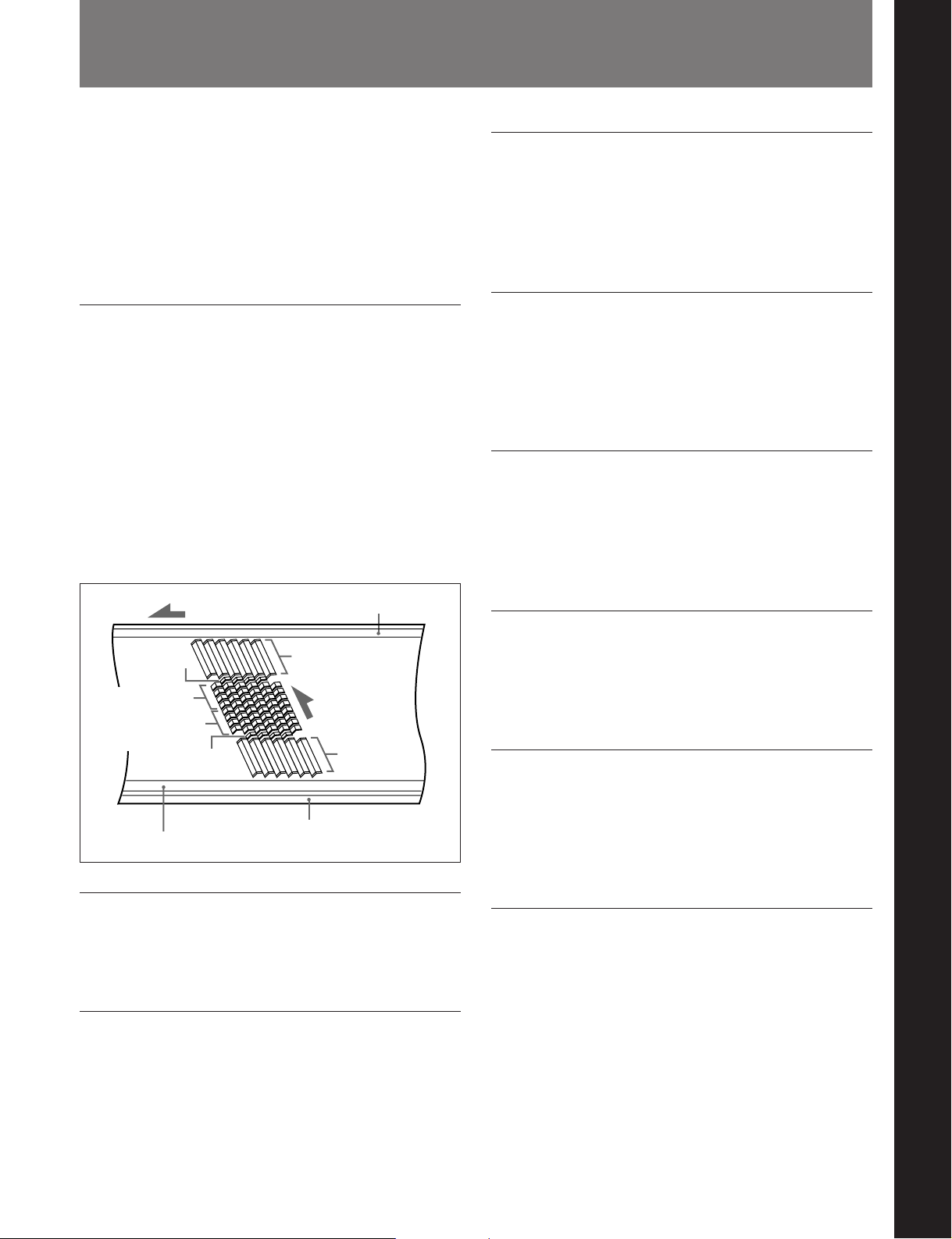
Tape transport direction
System data
Audio channels
1 to 4
Audio channels
1 to 4
System data
Control (CTL) track
Time code track
Auxiliary track
Video
Head
direction
Video
Head configuration
In addition to playback heads for Betacam SX, the unit
also has analog playback heads for Betacam SP.
Digital signal processing
This unit processes digital signals conforming to 4:2:2
component digital D-1 format.
Wide range of output signals
The unit can output the following signals.
•Analog video (composite)
•Analog audio (L and R)
Menu-based setup
Initial settings for the unit’s operating condition, the
interfaces with connected equipment, and so forth can
be made by menu operations on the front panel of the
unit.
Wide range of indications
In addition to the LED display which shows the
operating status and current settings of this unit and
connected equipment, a fluorescent display is provided
to show numerical values including time code, user
bits, error messages, and setup menu information.
Chapter 1 Overview 1-1

1-1 Overview
Minimal maintenance
Chapter 1 Overview
The design needs minimal maintenance, and requires
no daily maintenance or checks. The drum and other
components have reduced maintenance costs.
Rack mounting
The unit can be mounted in an EIA standard 19-inch
rack.
For details of rack mounting, refer to the Maintenance
Manual Part 1.
1-2 Chapter 1 Overview
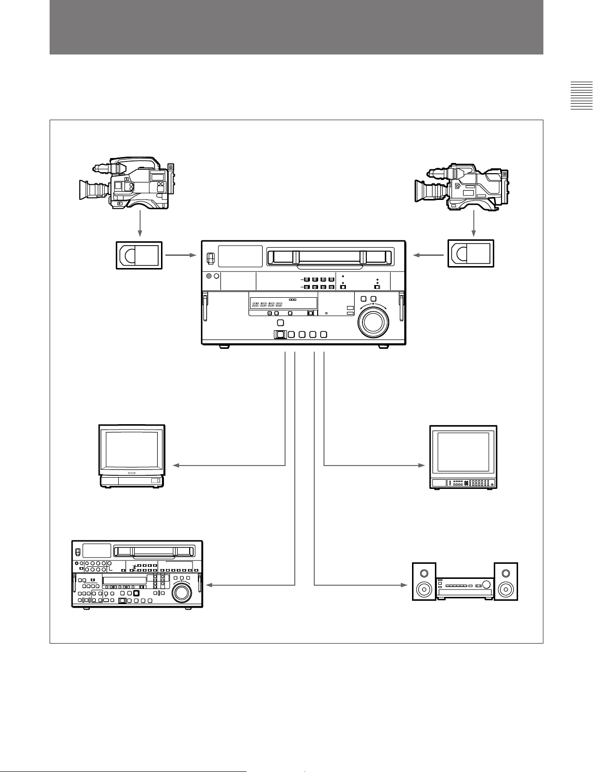
1-2 Example System Configuration
The following conceptual diagram shows an example
system configuration.
Chapter 1 Overview
Betacam SX camcorder
Digital cassette
Betacam SP camcorder
Analog cassette
DNW-A22/A22P
TV set
Analog VTR
Using RFU-89KB
RFU Adaptor.
Analog composite
Analog composite
Video monitor
Analog audio
Audio monitor
Chapter 1 Overview 1-3

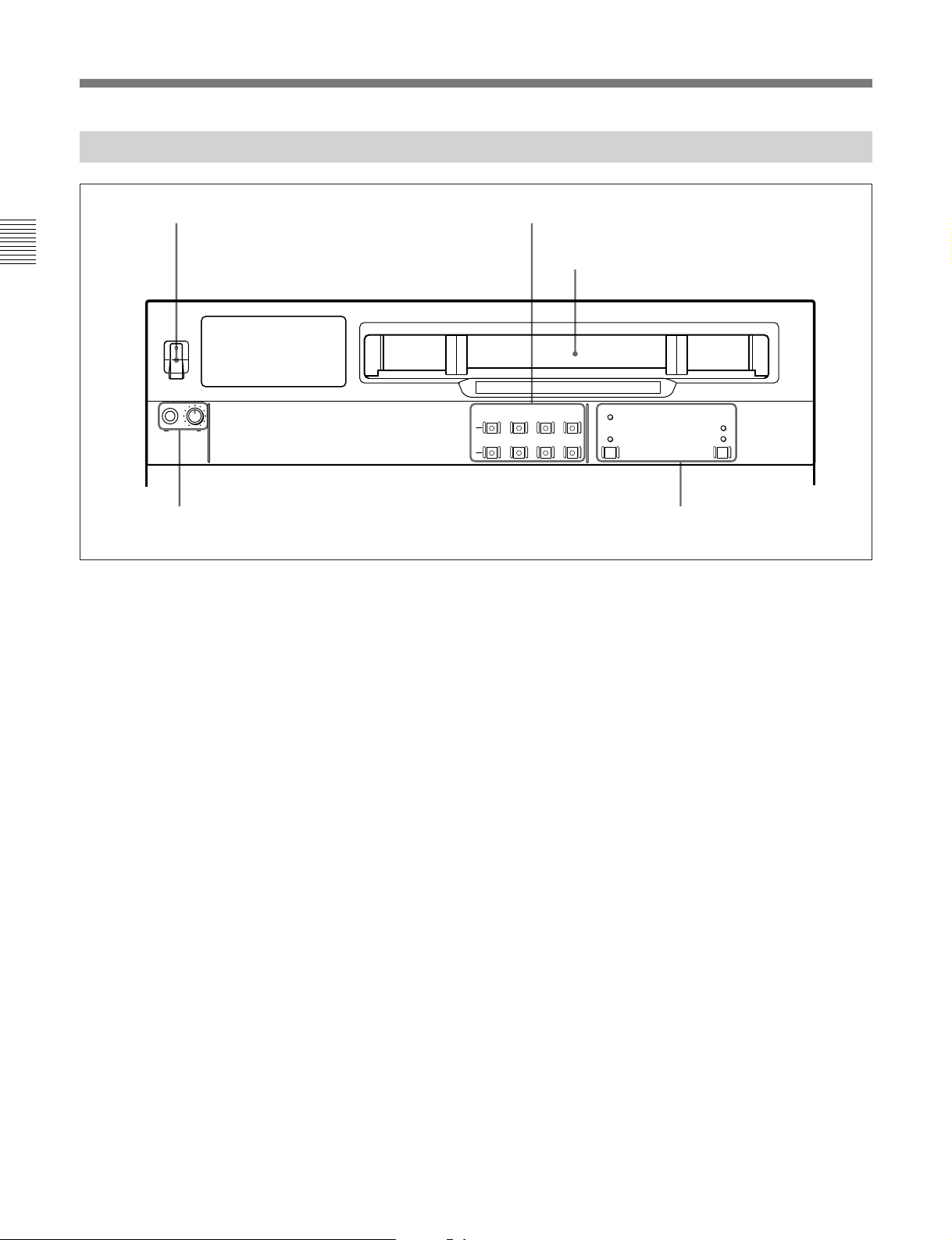
2-1 Control Panels
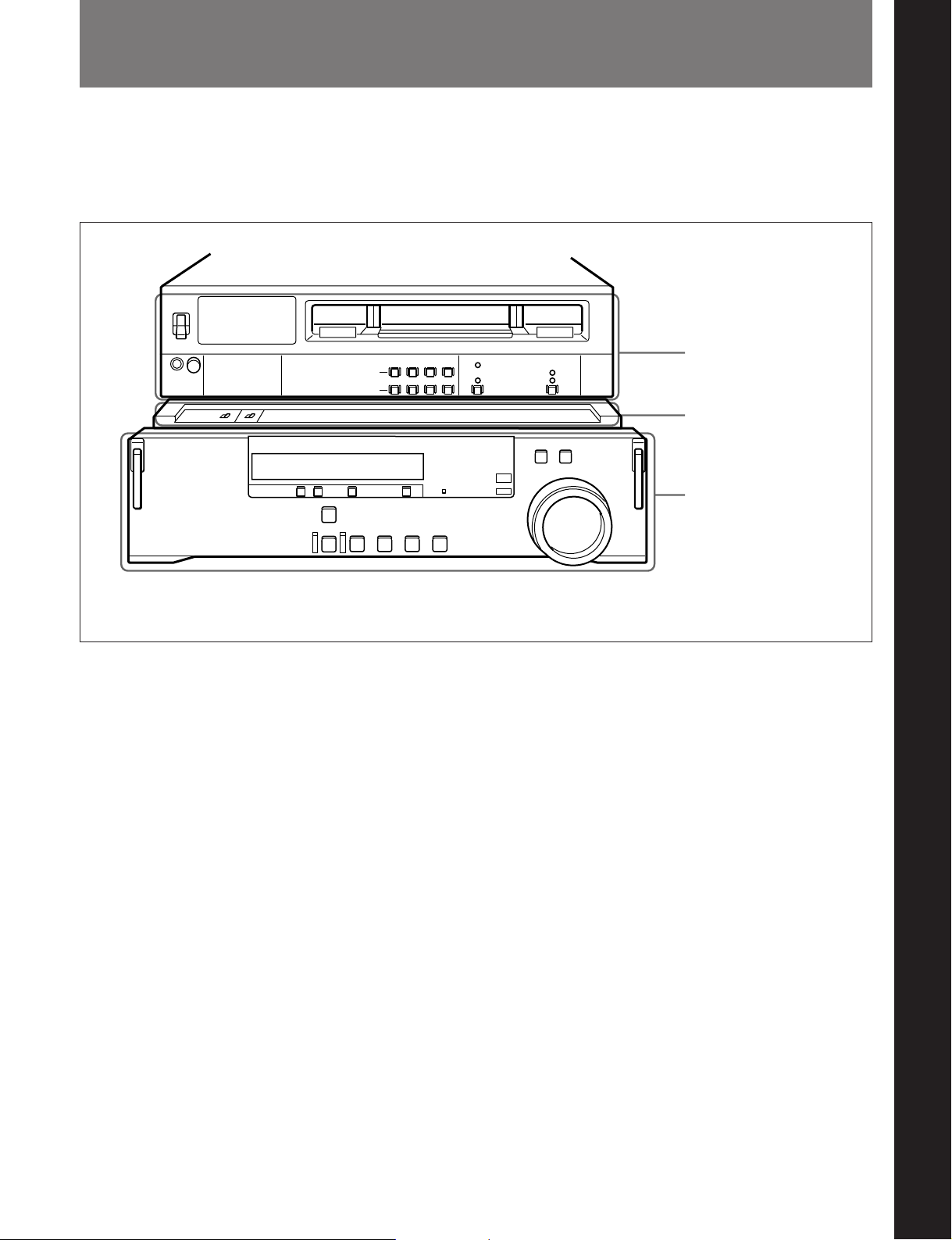
There are three front control panels, as follows:
•Upper control panel
•Subsidiary control panel
•Lower control panel
Chapter 2 Location and Function of Parts
Chapter 2 Location and Function of Parts
Upper control panel
(See page 2-2.)
Subsidiary control panel
(See page 2-8.)
Lower control panel
(See page 2-4.)
To reveal the subsidiary control panel, pull the lower control panel forward.
Chapter 2 Location and Function of Parts 2-1
2-1 Control Panels
2-1-1 Upper Control Panel
1 POWER switch
Chapter 2 Location and Function of Parts
POWER
ON
OFF
PHONES
1 POWER switch
This powers the unit on and off. When the unit is
powered on, the fluorescent display in the lower
control panel lights.
To power the unit off, press the side of the POWER
switch marked “OFF”.
2 AUDIO MONITOR SELECT buttons
Cassette compartment
ANALOG /
DIGITAL
AUDIO MONITOR SELECT
CH-1 CH-2 CH-3 CH-4
L
R
LTC
VITC
TC
DF
NDF
3 PHONES jack and control 4 Time code setting section
2 AUDIO MONITOR SELECT buttons
Press the buttons in the L and R rows to select the
audio signal channels (channels 1 to 4, identified as
CH-1 to CH-4) output from the MONITOR OUTPUT
L and MONITOR OUTPUT R connectors.
You can press two or more buttons simultaneously in
each row, turning them on, to monitor an output
produced by mixing the selected channels.
2-2 Chapter 2 Location and Function of Parts
3 PHONES jack and control
Connect stereo headphones with an impedance of 8
ohms, to monitor the sound during playback and
editing.
The control knob adjusts the volume.
It is possible to make a setting so that the output
volume from the MONITOR OUTPUT connectors is
controlled simultaneously.
In order that the output volume from the MONITOR
OUTPUT connectors can be controlled simultaneously, an
internal board switch setting is required. For details, refer
to the Maintenance Manual Part 1.
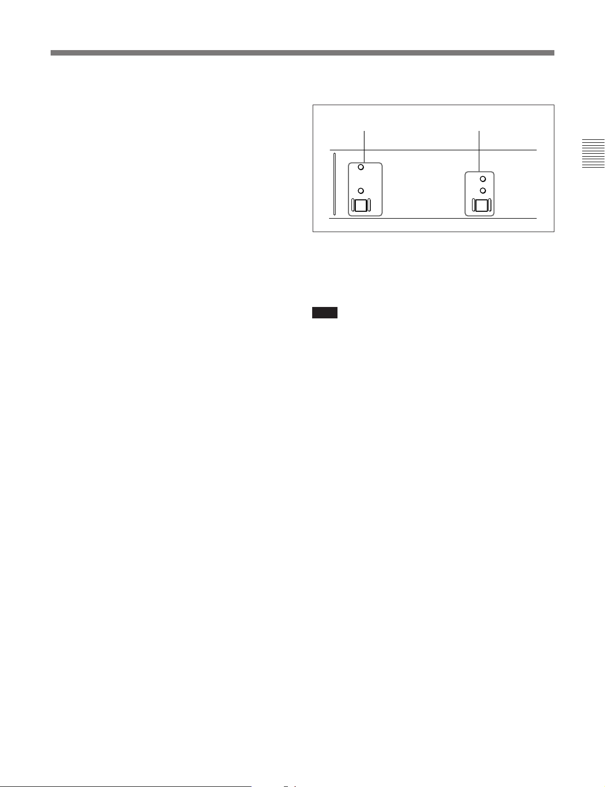
4 Time code setting section
TC switch and indicators DF/NDF switch and indicators
LTC
DF
VITC
TC
NDF
TC (time code) switch and indicators
1)
This switch selects LTC
or VITC2) as the time code
displayed in the lower control panel. The indicator
corresponding to the selection lights.
Note
In this unit, VITC may not be displayed correctly
except during normal playback.
DF/NDF (drop-frame/non-drop-frame) switch and
indicators
In a 525/60 system, this switch selects the
mode of advancing the time code generator and CTL
counter.
DF: Drop-frame mode.
NDF: Non-drop-frame mode.
3)
3)
The indicator corresponding to the selection lights.
Chapter 2 Location and Function of Parts
..........................................................................................................................................................................................................
1) LTC: abbreviation of Longitudinal Time code. This
time code is recorded on a longitudinal track on the tape.
Reading is unreliable at low speeds, and not possible at
all during still playback.
3) Drop-frame/non-drop-frame mode: In the NTSC
system, the actual frame rate is 29.97 frames per second.
There is therefore a cumulative discrepancy between the
actual frame rate and the 30 frames per second rate on
which time code is based. In drop-frame mode, except
2) VITC: abbreviation of Vertical Interval Time code.
This is inserted in the vertical blanking interval and
recorded on the video tracks.
once every 10 minutes, the first two frames are skipped
at the beginning of each minute to keep the time code
values in step with actual elapsed time. In non-dropframe mode, the correction is not carried out, and there is
a discrepancy of about 86 seconds per day between
actual elapsed time and time code values.
Chapter 2 Location and Function of Parts 2-3
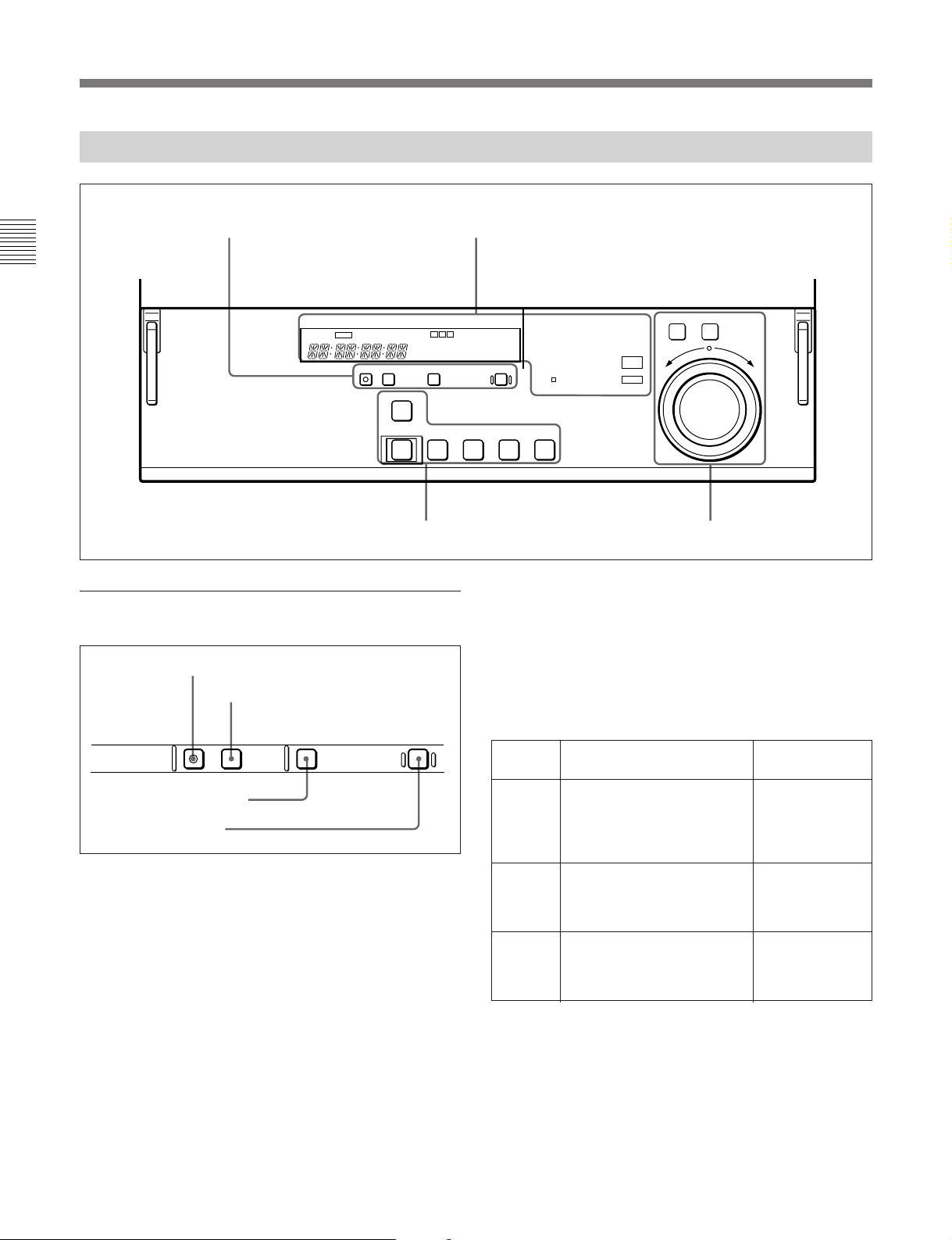
2-1 Control Panels
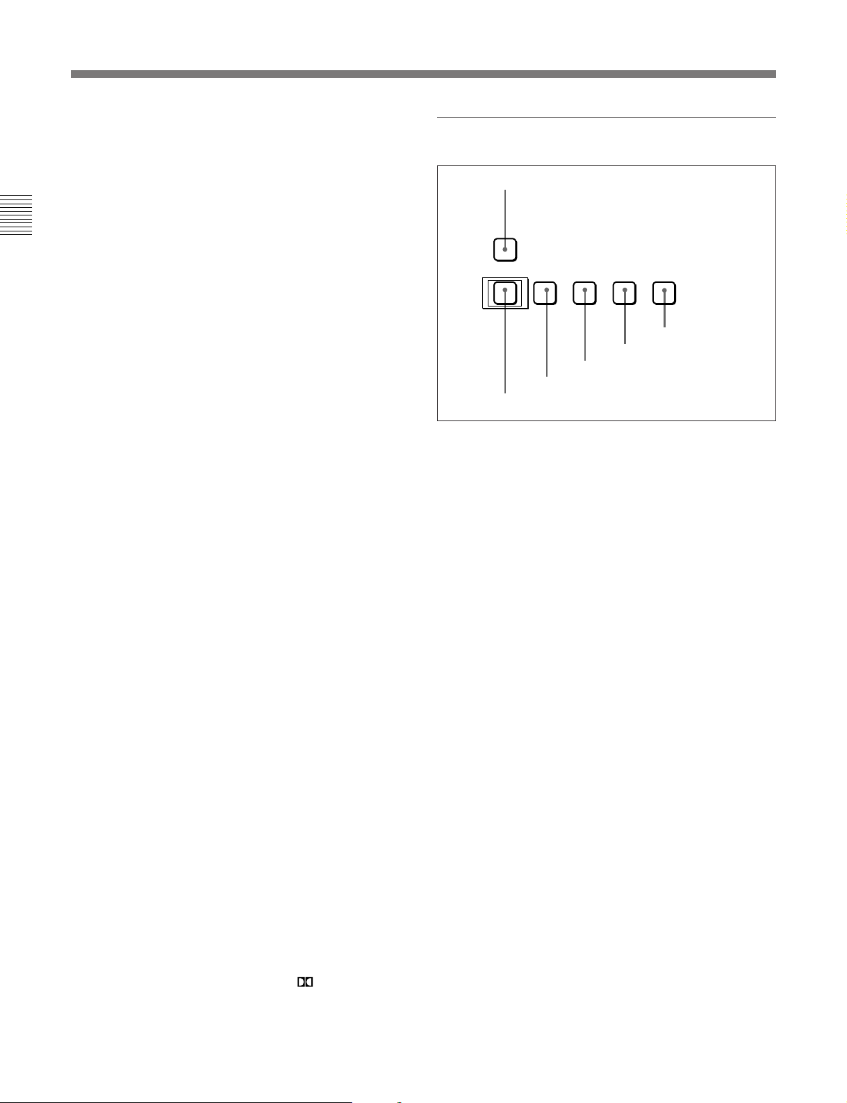
2-1-2 Lower Control Panel
Chapter 2 Location and Function of Parts
2 Display section1 Menu/display setting section
CH
VI TC UB
INTRP DF LTC VITC 4F
MENU SET RESETCTL/TC/UB
CONDITION
STANDBY
EJECT REW PLAY F FWD STOP
6
0
3 Tape transport control section
1 Menu/display setting section
1 MENU button
2 SET button
MENU SET RESET
3 CTL/TC/UB button
4 RESET button
1 MENU button
Use this button for setup menu operations.
Pressing this button, turning it on, displays setup
menus in the fluorescent display of the display section
2. Press the button once more to exit from the menu
display.
For details of setup menu operations, see Chapter 5, “Menu
System”.
CTL/TC/UB
SHUTTLE JOG
DOLBY
525 625
NR
SERVO
)
9
p
REVERSE FORWARD
BETACAM
SX
ALARM
4 Search control section
3 CTL/TC/UB button
This selects the value displayed in the fluorescent
display in the following sequence: CTL, TC, UB. As
the display changes, the corresponding indicators over
the fluorescent display also show the status.
Time code display value selection and display contents
Display
selection
CTL Tape running time (hours,
TC Playback time code read by
UB User bit value inserted in the
a) The selection of LTC or VITC is made by the TC switch.
When VITC is selected, the VITC indicator over the TC
switch lights.
Value displayed
minutes, seconds, frames)
computed from the CTL
(control) signal recorded on
the tape during playback.
the internal time code
a)
reader.
playback time code.
a)
Indicator status
TC and UB
indicators are
both off.
The TC indicator
lights and the UB
indicator goes
off.
The UB indicator
lights and the TC
indicator goes
off.
2 SET button
Use this button for setting time code and user bit
values and in setup menu operations.
For details of setup menu operations, see Chapter 5, “Menu
System”.
2-4 Chapter 2 Location and Function of Parts
4 RESET button
To reset a CTL, time code (TC) or user bit (UB) value
displayed in the fluorescent display, hold this button
down.
Resetting the CTL value erases all edit points.
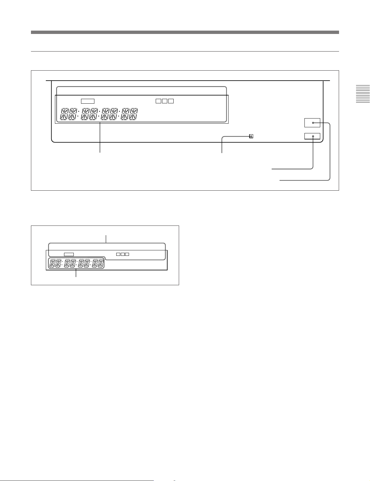
2 Display section
VI TC UB
INTRP DF LTC VITC 4F
CH
CONDITION
525 625
DOLBY
NR
BETACAM
SX
Chapter 2 Location and Function of Parts
1 Fluorescent display and indicators
1 Fluorescent display and indicators
This comprises a time data display area and a number
of indicators.
Indicator area
CH
VI TC UB
INTRP DF LTC VITC 4F
Time data display area
CONDITION
525 625
DOLBY
NR
Time data display area
Normally this displays a CTL count, time code value,
or user bit value according to the setting of the CTL/
TC/UB button in the menu/display setting section 1
and the setting of the TC switch in the upper control
panel.
It is also used to display error messages and setup
menus.
For details of the selection of CTL count, time code value,
or user bit value, see the description of the CTL/TC/UB
button (previous page).
SERVO
2 SERVO Indicator
3 ALARM indicator
4 BETACAM SX indicator
ALARM
Indicator area
This includes the following indicators.
•TC (time code) indicator: This lights when a time
code is displayed in the time data display area.
•UB (user bits) indicator: This lights when a user
bit value is displayed in the time data display area.
•VI (VITC) indicator: When a VITC time code
value or VITC user bit value is displayed in the
time data display area, this indicator lights
together with the TC or UB indicator.
•INTRP (interpolation) indicator: This lights
when a playback time code reading error is
interpolated using the CTL signal.
•DF (drop-frame) indicator: This lights when a
displayed time code value is in drop-frame mode.
•LTC, VITC indicators: Regardless of the display
in the time data display area, these indicators light
when the corresponding time code values are
being read.
•CH (channel) CONDITION indicator: A three-
color indicator shows the state of the playback
signal.
Green: The state of the playback signal is good.
Yellow: The playback signal is somewhat
deteriorated, but playback is possible.
Red: The playback signal is deteriorated.
When this indicator remains on, head cleaning
or an internal inspection is necessary.
Chapter 2 Location and Function of Parts 2-5
2-1 Control Panels
•525, 625 indicators: The indicator showing the
number of scan lines for the television standard
selected using basic menu item 013 lights (NTSC:
525 scan lines, field frequency 60 Hz; PAL: 625
scan lines, field frequency 50 Hz).
•DOLBY NR indicator: This lights when the Dolby
Chapter 2 Location and Function of Parts
noise-reduction
2 SERVO indicator
This indicator lights when the drum servo and capstan
servo are locked
normally.
3 ALARM indicator
This lights when a hardware error is detected on the
unit, and goes off when the error is resolved.
When this indicator is lit, an error message appears in
the fluorescent display. If you are using the
COMPOSITE VIDEO OUTPUT 2 (SUPER)
connector, then when the CHARACTER switch in the
subsidiary control panel is set to ON, the error
message also appears on the monitor screen.
4 BETACAM SX indicator
When playing back a tape recorded in Betacam SX
format, this indicator lights.
1)
circuit is functioning.
2)
and the tape is being played back
3 Tape transport control section
1 STANDBY button
STANDBY
EJECT REW PLAY F FWD STOP
6
0
5 REW button
6 EJECT button
1 STANDBY button
When a cassette is inserted and this button is off, to put
the VTR in standby mode, press the button, turning it
on.
In standby mode, the drum is rotating and the tape is in
contact with the drum. As a result, playback can start
immediately.
To end standby mode, press the STANDBY button,
turning it off.
If 8 minutes (value can be varied using extended menu
item 501) elapse in standby mode, the unit
automatically switches out of standby mode to protect
the tape.
)
9
3 F FWD button
4 PLAY button
p
2 STOP button
2 STOP button
To stop playback, press this button, turning it on.
3 F FWD (fast forward) button
To fast forward the tape, press this button, turning it
on.
..........................................................................................................................................................................................................
1) Dolby noise reduction manufacutured under license from
Dolby Laboratories Licensing Corporation.
“DOLBY” and the double-D symbol are trademarks
of Dolby Laboratories Licensing Corporation.
2) Servo lock: This refers to the synchronization of the
phase of the drum rotation and the reference signal for the
tape transport position, so that the video heads can trace
the same pattern on the tape for playback or recording.
2-6 Chapter 2 Location and Function of Parts
 Loading...