

m!r
DIGITAL AUDIO
ADC”M55YU
COMPACT DISC CHANGER
CAMBIADOR DE DISCOS COMPACTOS
OWNER’S RECORD
For your convenience, record the model number
and serial number (you will find them on the rear of
your set) inthe space provided below. Please refer
to them when you contact your AIWA dealer in
case of difficulty.
Model No. lADC-M55
Seria’ ‘0 ~
Welcome
Thank you for your purchasing thw AIWA product.
through this manual carefully.
●TABLE OF CONTENTS
■FEATU13ES
● Tracks from 6 CDs stored in the disc magazine
can be selected and played.
● Horizontal, vertical, slanted or suspended
Installation can be made
To optimize the performance of this unit, please read
NOTE
This equipment has been tested and found to
comply with the limits for a Class B digital device,
pmumt to Part 15 of the FCC Rules. These
limits are designed to prowde reasonable
protection against harmful interference in a
residential installation.
This equipment generates, uses, and can radiate
radlofrequency energy and, if not installed and
used in accordance with the instructions, may
cause harmful interference to radio
communications. However, there is no guarantee
that interference will not occur in a particular
installation. Ifthis equipment does cause harmful
interference to radio or television reception, which
can be determmed by turning the equipment off
and on, the user is encouraged to try to correct
the interference by one or more of the following
measures:
1 ENGLISH
— Reorient or relocate the receiving antenna.
—Increase the separation between the
equipment and receiver.
—Connect the equipment into an outlet on
circuit different from that to which the recewer
ISconnected.
— Consult the dealer or an experienced radio/
TV technician for help.
CAUTION
Modifications oradjustmentsto this product, which
are not expressly approved by the manufacturer,
may void the user’s right or authority to operate
this product.
❑PRECAUTIONS
● Do NOT install the unit in a location where it
may be subjected to:
— Direct sunlight or other sources of excessive
heat
— Fluid, rain or moisture
— Excessive dirt or dust
— Excesswe vibration
● This unit is designed to be operated on a 12-volt
DC negative-ground electrical system only.
● Choose themounting location carefully so that
the unit will not interfere with normal driving
functions.
● Before making connections, dlsconnectthe@
termmal of the car battery to avoid short
circuiting,
Notes on CDs
● A defective or soiled disc stored in the disc
magazine can cause the sound to drop out
during play.
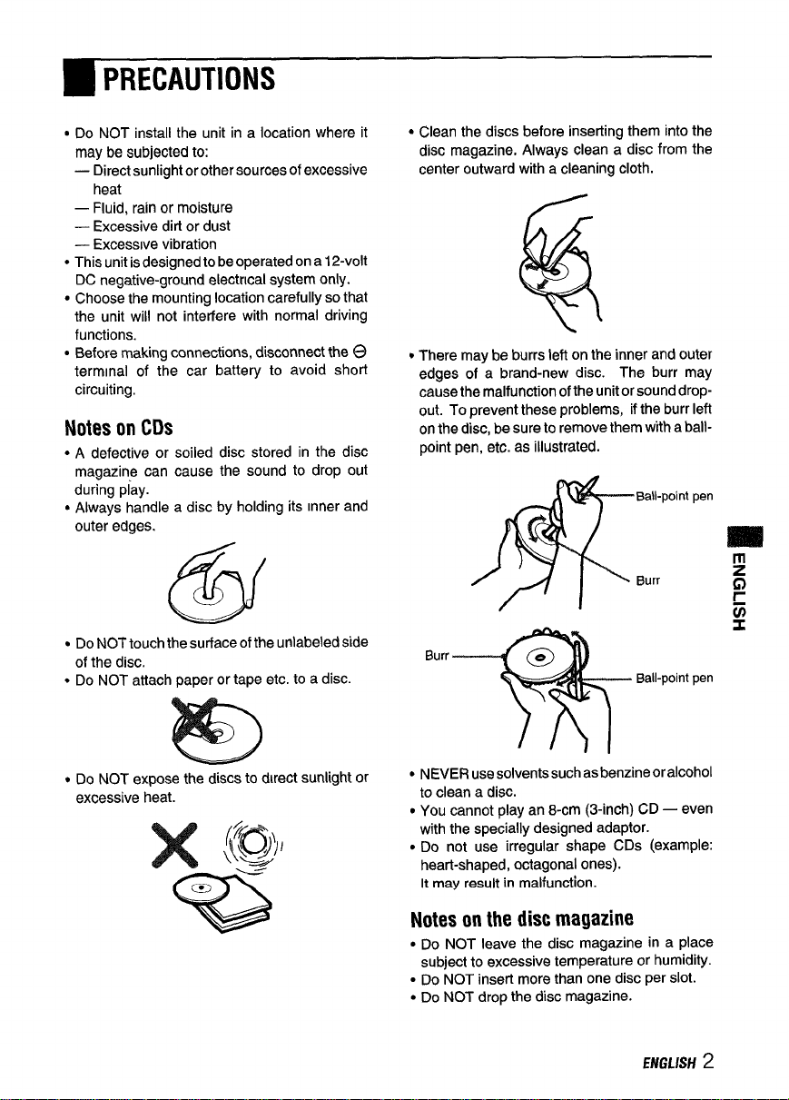
● Always handle a disc by holding its inner and
outer edges.
@iii
● Do NOTtouchthe surface of the unlabeled side
of the disc.
● Do NOT attach paper or tape etc. to a disc.
● Clean the discs before inserting them into the
disc magazine. Always clean a disc from the
center outward with a cleaning cloth.
● There may be burrs left on the inner and outer
edges of a brand-new disc. The burr may
cause the malfunction of the unit or sound dropout. Topreventthese problems, ifthe burrleft
on the disc, be sure to remove them with a ballpoint pen, etc. as illustrated.
Ball-point pen
Burr
Burr
@
Ball-point pen
● Do NOT expose the discs todirectsunhght or
excessive heat.
%
● NEVER usesolvents suchasbenzine oralcohol
to clean a disc.
● You cannot play an 8-cm (3-inch) CD — even
with the specially designed adaptor.
● Do not use irregular shape CDs (example:
heart-shaped, octagonal ones).
It may result in malfunction.
Notes on the disc magazine
● Do NOT leave the disc magazine in a place
subject to excessive temperature or humidity.
● Do NOTinsert more than one disc per slot.
● Do NOT drop the disc magazine.
ENGLISH2
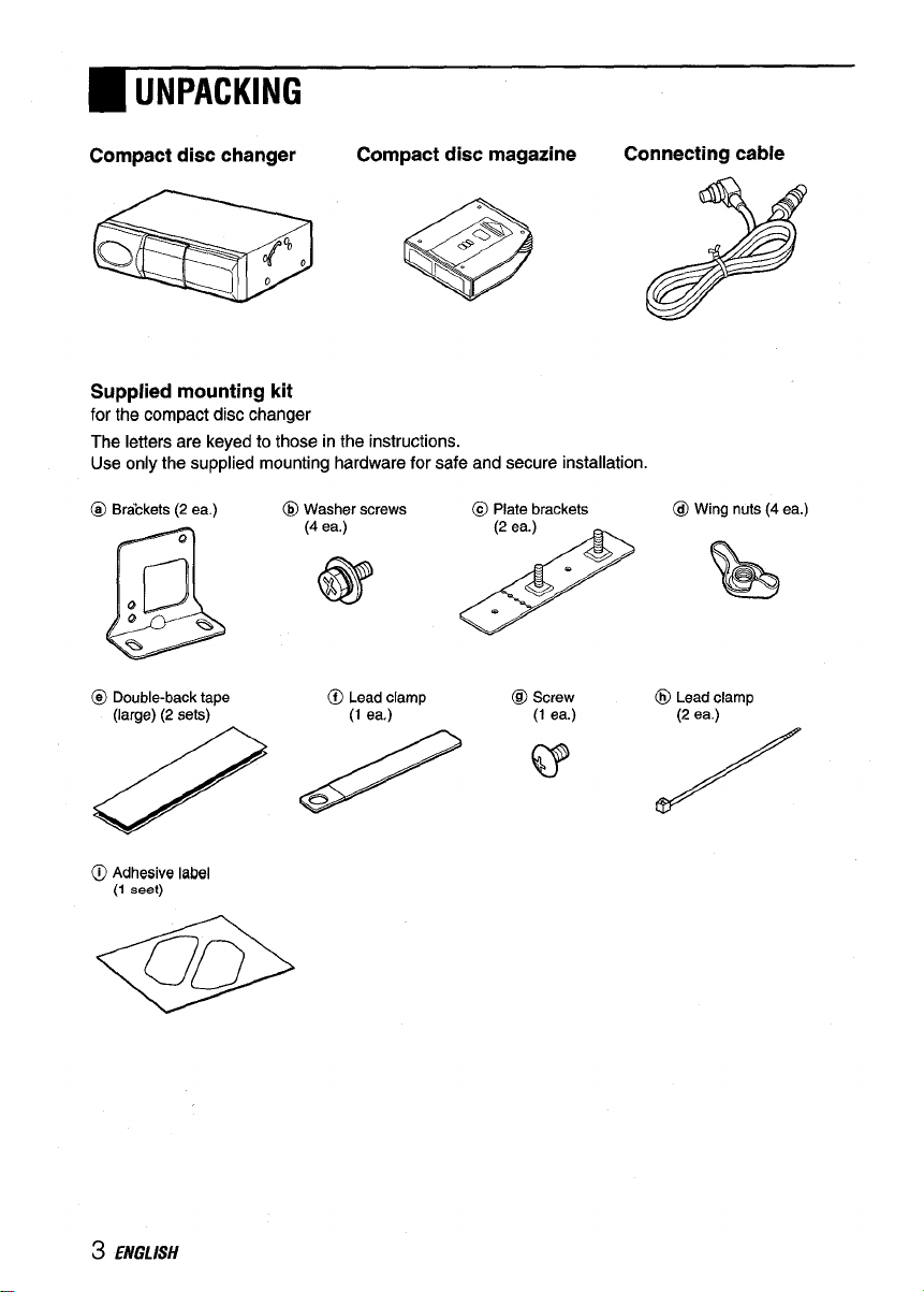
●UNPACKING
Compact disc changer
,
Q
/’%0
o
Compact disc magazine
e
Supplied mounting kit
for the compact disc changer
The letters are keyed to those in the instructions.
Use only the supplied mounting hardware for safe and secure installation.
@ Brdckets (2 ea.) @ Washer screws @ Plate brackets
@(G2’
@ Double-back tape
(large) (2 sets)
0 ~;; ;Iamp
@ Screw @ Lead clamp
Connecting cable
@ Wing nuts (4 ea.)
// ‘) 7
3 ENGLISH
●INSTALLATIONS
Precautions
Select the mounting location very carefully,
referring to the following points.
● Make sure that there is no fuel tank, wiring or
piping ontheothersideof the mounting surface.
● Make sure that the installation of the unit will not
hinder the movement of the deck lid or interfere
with the spare tire, etc.
● Use only the supplied mounting kit for safa and
proper installation.
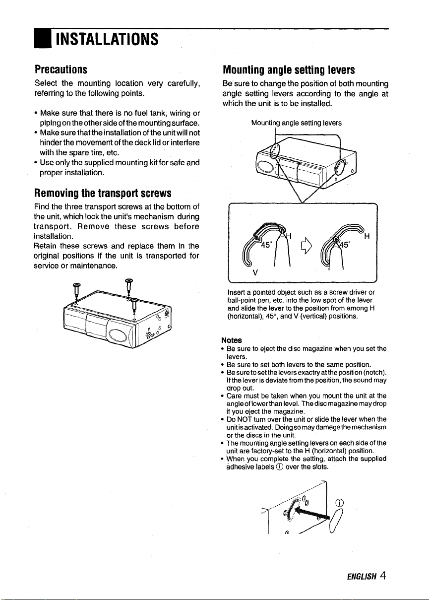
Removing the transport screws
Find the three transport screws at the bottom of
the unit, which lock the unit’s mechanism during
transport. Remove these screws before
installation.
Retain these screws and replace them in the
original positions if the unit is transported for
service or maintenance.
@ 77
Mounting angle setting levers
Be sure to change the position of both mounting
angle setting levers according to the angle at
which the unit is to be installed.
Mounting angle
insert a
pointed object such es e screw driver or
ball-point pen, etc. into
and
slide the leverto the position from among H
(horizontal), 45”, and V (vertical) positions.
Notes
● Be sure to eject the disc magazine when you set the
levers.
● Be sure to set both levers to the same position.
● Be suretosetthe leversexactryatthe poeition (notch).
If the lever iadeviate from the position, the sound may
drop out.
● Care must be taken when you mount the unit at the
angle of Iowerthan level, The disc magazine may drop
If you eject the magezine.
● Do NOTturn overthe unit or slide the lever when the
unit isactivated. Doing so may damege the mechanism
or the discs in the unit.
● The mounting angle setting levers on each side of the
unit are factory-set to the H (horizontal) position.
● When you complete the setting, attach the supplied
adhesive labels @ over the slots.
setting levers
I
the low spot of the lever
ENGLISH 4
●INSTALLATIONS
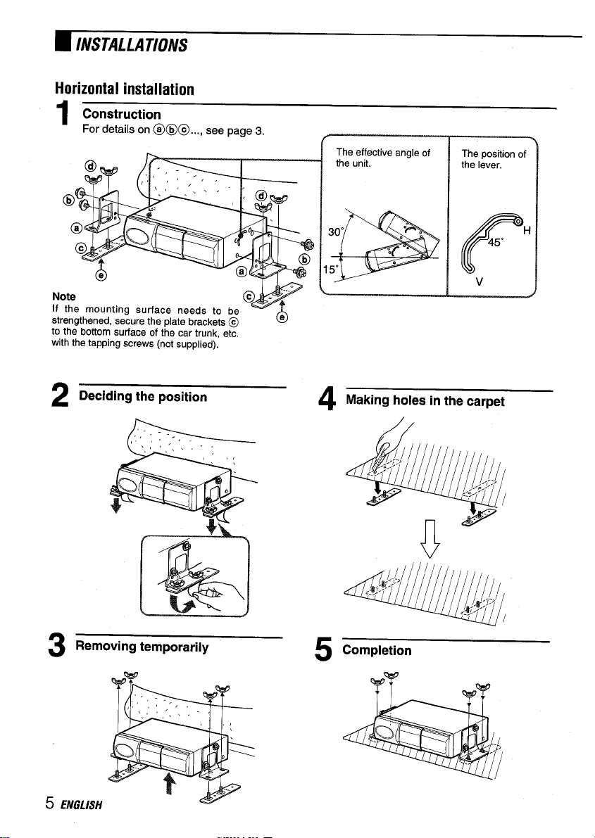
Horizontal installation
Construction
1
For details on @@@..., see page 3.
N
If
St
to the bottom surface of the car trunk, etc.
with the tapping screws (not supplied).
Deciding the position
2
Removing temporarily
3
Making holes in the carpet
v
Completion
5
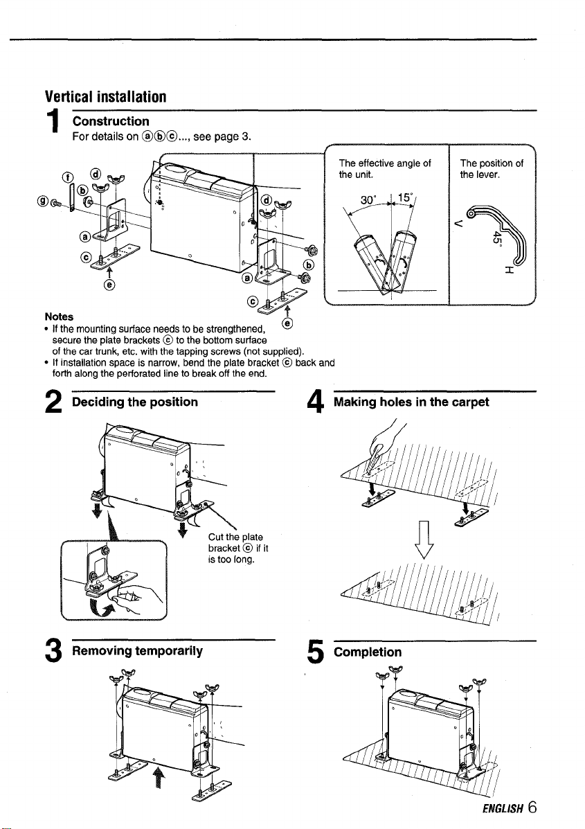
Vertical installation
Construction
1
For details on @@@..., see page 3.
secure the plate brackets @ to the bottom surface
of the car trunk, etc. with the tapping screws (not supplied).
● If installation space is narrow, bend the plate bracket@ back and
forlh along the perforated line to break off the end.
#-
The effective angle of
the unit. the lever.
I
The poeition of
Deciding the position
2
Removing temporarily
3
Making holes in the carpet
4
Completion
5
ENGLISH 6
●INSTALLATIONS
-ThepOsi
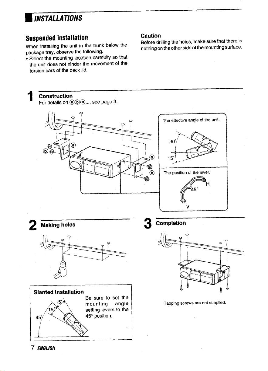
Suspended installation
When installing the unit in the trunk below the
package tray, observe the following.
● Select the mounting location carefully so that
the unit does not hinder the movement of the
torsion bars of the deck lid.
Construction
1
For details on @@@..., see pa9e 3.
Caution
Before drilling the holes, make sure that there is
nothing on theothersideof the mounting surface.
/-
The effective angle of the unit.
4 “
.
‘P .
.
15“
30”
P
-%
2
Slanted installation
7 ENGLISH
set the
angle
s to the
3
Completion
%
Tapping screws are not supplied.
●CONNECTIONS
‘ti
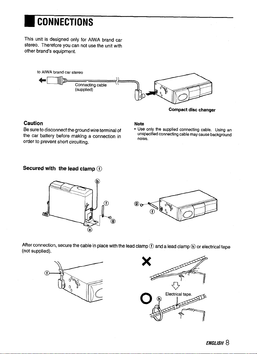
This unit is cksigned Only for AIWA brand car
stereo. Therefore you can not use the unit with
other brand’s equipment.
to AIWA brand car stereo
+-
Connecting cable
(supplied)
“~=
Compactdisc changer
Caution
Be sure to disconnect the ground wire terminal of
the car battety before making a connection in
order to prevent short circuiting.
Secured with the lead clamp @l
63
After connection, secure the cable in place with the lead clamp@) and a lead clamp@ or electrical tape
(not supplied).
Note
● Use only the supplied connecting cable. Using an
unspecified connecting
noise,
ceble maycausebackground
.4
,
‘M
ENGLISH 8
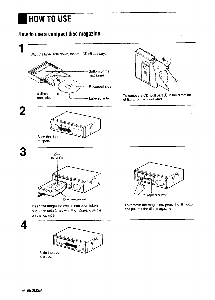
●HOW TO USE
How to use a compact disc magazirw
1
With the label side down, insert a CD all the way.
Bottom of the
magazine
Recorded side
2
o~ , 4°00
Q
Slide the door
to open.
3
Disc magazine
Insert the magazine (which has been taken
out of the unit) firmly with the &mark visible
on the top side.
4
Labeled side
0
To remove a CD, pull part@ in the direction
of the arrow as illustrated.
To remove the magazine, press the A button
and pull out the disc magazine.
Slide the
to close

~ SPECIFICATIONS
Notes on the disc magazine
● Be sure to align the edge of the disc to both
grooves of the disc tray when you set the disc.
If a disc is not set properly, it may cause
damage to the unit,
Disc magazine
Disc tray
● Thedisctraymay betakenoff from the magazine
if you pull the tray forcibly. Ifthe tray was taken
off, push it into the magazine while pressing the
part @as illustrated. Be sure that both ends of
the tray are aligned to the grooves of the
magazine correctly.
Compact disc changer
System
Frequency response 5 Hz – 20 kHz
Wow and flutter
Signal to noise ratio 91 dB or more
outputs Line output (for changer
Operating temperature
Dimensions 225 x63x 175 mm (w/h/d)
Weight
Power requirement 12 V DC car bettery
DIA converter
Sampling rate 44.1 kHz
Disc size 120 mm
Supplied accessories Disc magazine (1)
Design and specifications are subject to change without
notice.
Compact disc digital audio
system
Below measurable limit
connector only)
-10
“c to 55 “c
(8 7/sx21/2
1,7 kg
(3.74 Ibs.)
(negative ground)
1 bit DAC, 8 times over
sampling
Mounting kit (1 set)
Connecting cable (5 m)
(16.4 ft.) (1)
x 7 in.)
DISCtray
‘T
Disc
magazine
ENGLISH 10

Bienvenidos
Muchas gracias por su compra de este producto AlWA. Para utilizar este aparato en Ias mejores
condlciones posibles, lea cuidadosamente Ias mstrucciones de este manual.
●INDICE
BDETALLES
● Se pueden seleccionar y reproducer canciones
de 6 discos compactos colocados en el cargador
de discos.
●Se puede instalar horizontal mente,
verticalmente, inclinado y colgado de alg(m
Iado,
PRECAUTION
Las modificaciones y ajustes de este producto
que no han sido autorizadas a tftulo expreso por
el fabricate pueden anularel derecho o autoridad
del usuario para hater funcionar este producto.
1 ESPAifOL

❑PRECAUCIONES
● NOinstale launidaden un Iugardondepueda
quedar expuesto a:
— Ios rayos del sol o a temperatures muy altas.
— Iiquido, Iluvia o humedad.
— demasiada suciedad o POIVO
— vibration excesiva
● Este aparato funciona solo con CC de 12 voltios
con conexion a tlerra negativa.
● Seleccione cuidadosamente el Iugar para la
instalacion detal forma que elaparato no intetilera
con Ias funciones de conduction normales.
● Antes de hater Ias conexiones, desconecte el
terminal @ de la bateria del coche para evitar
un cortocircuito.
Notas sobre Ios discos compactos
● Sise ha colocado un disco sucio o con defectos
en el cargador de dkcos, el sonido puede
desaparecer a veces durante su reproduction.
● Sujete el disco por sus hordes interiors y
exteriors.
/
● NO toque el Iado de la superficie sin etiqueta
del disco.
● NO pegue papeles ni cintas, etc. en el disco.
● Litnpie Iosdiscos antes de colocarlos enel cargador
de discos. Empiece slempre por el centro y vaya
h~cia afuera Iimpiando con un paho Iimpiador.
\
c Pueden quedar rebabas en Ios hordes interior
y exterior de un disco nuevo. Las rebabas
pueden provocar una averia del aparato o
caidas en el sonido. Para evitar estos
ptoblemas, si quedan rebabas en el disco,
eliminelas con un boligrafo, etc., tal como en la
figura.
Bolfgrafo
Rebabas
Re,babas
@
Boligrafo
m
$
;
21
p
● NOdejequeel disco quedeen un Iugarexpuesto
a Ios rayos del sol o a temperatures muy altas.
%
● NO utilice disolventes tales como bencina o
alcohol para Iimpiar un disco.
● NO se pueden reproducerIosdiscos compactos de
8 cm (3 pulgadas) ni siquiera colocandolos en un
adaptadordiseiiado especialmente paratal efecto.
● No utilice dmcos compactos de formas
irregulars (per ejemplo con forma de corazon
u octogonales). Pueden provocar una averia.
Notas sobre el cargador de discos
● NO deje el cargador de discos en un Iugar
donde quede expuesto agrandestemperaturas
o lugares muy humedos.
● NO coloque mas de un disco en cada ranura.
● NO deje caer el cargador de discos.
ESPANOL
2

●DESEMBALAJE
Cambiador de discos Cargador de discos Cable de conexi6n
compactos
Juego de montaje suministrado
para el cambiador de discos compactos
Las Ietras en circulos tienen sus referencias a 10Iargo de Ias instrucciones.
Utilice s610 Ias piezas para montaje suministradas para que la instalacion sea segura.
compactos
@ Mensulas (2 c/u) @ Tornillos con
@
Cinta de doble superficie
adhesiva (grande)
(2 juegos)
@ Etiqueta adhesiva (1 hoja)
arandala (4 c/u)
~ Abrazadera de
plomo (1 c/u)
@ Mensulas de
placa (2
c/u)
@) Tornillo (1 c/u)
@ Tuercas de aleta
(4 c/u)
@ &::;deras de plomo
/
3 ESPAflOL

■INSTALACIONES
Precauciones
Seleccione cuidadosamente el Iugar donde se
va a instalar, teniendo en cuenta Ios siguientes
puntos.
● Confirmeque no haya untanque decombustible
detras de Iasuperficie de montaje yque tampoco
haya cables o caiios.
● La instalacion de la unidad no debera impedirel
movimiento de la tapa del haul ni el desmontaje
de la rueda de repuesto, etc.
● Utilice solo el juego de montaje suministrado
con el equipo para que la instalacion se haga
correctamente y de forma segura.
Desmontaje de Ios tornillos de
transport
Busque Ios tres tornillos de transport que estan
en la parte inferior del aparatoy que fijan el
mecanismo del aparato durante su transport.
Saque estos tornillos antes de la instalacion y
coloque Ias etiquetas adhesivas suministradas
sobre Ios orificios.
Guarde Ios tornillos y vuelva a colocarlos en sus
posiciones originales en caso de Ilevar o enviar
el aparato para su servicio o mantenimiento.
Instalacion de Ios herrajes de angulo
Cambie la position de instalacion de Ios herrajes
de angulo de acuerdo al angulo en el que desea
instalar el aparato.
Angulo de instalacion
H
o
v
Introduzca un objeto puntiagudo, por ejemplo un
destornillador superfino o bolfgrafo, etc. en Ios
ojetes protectors moviles y deslice Ios ojetes
protectors ala position deseada, H
(horizontal), 45’0 V (vertical).
Notaa
.
Expulse sin falta Ios cargadores de disco antes de
colocar Ioa ojetes protectors.
● Instale ambos ojetes protectors en la misma position.
● Los ojetes protectors deben estarasentados en el
Iugarespecificado para Iaposicion deseada; de 10
contrario la position de la unidad puede provocar una
ca(da del sonido.
● Debe tenerse cuidado para instalar el angulo de Ie
unidad con el Iado delantero mas abajo que el trasero.
Elcargador de disco puede caerse cuando 10expulse.
● NO inviertala unidad odeslice Iosojetee protectors
cuando el aparato esta activado. Esto puede dafiar el
mecanismo o Ios discos en el aparato.
● Loa herrajes de angulo de instalacion en cada Iado de
la unidad se han ajustado de fabrica a la posici6n
(horizontal).
● Cuando se completa el ajuste, pegue Ias etiquetas
adhesives@) sobre Ias ranuras.
45”
6
H
ESPAtiOL 4

~ INSTALACIONES
Instalacion horizontal
Nota
Si fuera necesario reforzar la superficie de
instaiacion, asegure Ias mensulas de placa
@en la auperficie inferiordel batil del coche
con tornillos autoterrajantes (no incluido).
Position del
ojete protector.
v
Decida la position
2
Desmontaje provisorio
3
Abra orificios en la alfombra
4
Fin
5
5 ESPAiOL

Instalacilln vertical
Disefio
1
Para mas detalles de @@@..., lea la pagina 3.
con tornillos autoterrajantes (no incluido),
● El espacio para su instalacion es angosto, doble la mensula
@ hacia atras Y hacia adelante a 10Iargode la Iinea
peforada para romper la punts,
Position del
ojete protector,
Decida la position
2
F==%27-
. ,
+“
A-
M
Desmontaje provisorio
,,
0’, .
+
Corte la mensula
de placa @ si
esta muy Iargo.
Abra orificios en la alfombra
4
Fin
5
ESPAiiOL
6

●INSTALACIONES
Instalacion colgada
Cuando se instala la unidad en el baui, debajo de
la bandeja para paquetes, tenga en cuenta Ios
siguientes puntos.
● Seleccione cuidadosamente el Iugar donde se
va a instalar la unidad, para que no impida el
movimiento de Ias barras de soporte de la tapa
del haul.
Diseiio
1
Para mas detalles de @@@..., lea la pagina 3.
Precaution
Verifique que no haya nada detras del Iugarde la
instalaci6n antes de abrir Ios orificios.
Angulo efectivo del aparato.
Position del ojete protector.
v
Abra orificios
2
a
Instalacion inclinada
15°
15°
45”
. .
A
7 ESPA/fiOL
Instale Ios herrajes
de angulo para la
instalacion a la
position de 45.
.
0
3
Fin
Nose incluyen Ios tornillos
auto-roscadores.

●CONEXIONES
‘ti
Este aparato fue diseiiado solo para Ios estereos
de coche AlWA. Por 10 tanto, no utilice este
aparato con equipos de otra marca.
al estereo de coche de la marca AIWA
em
Cable de conexion
(suministrado)
‘+&e
Cambiador de discos
compactos
Precaution
Desconecte el terminal del cable a tierra de la
bateria del coche antes de hater Ias conexiones,
para evitar un cortocircuito.
Asegurado con la abrazadera de plomo (@
Despues de la conexion, asegure el cable en su Iugarcon unaabrazadera de plomo @ y una abrazadera
de plomo @ o
cinta aislante-(no incluida). -
Nota
● Utilice solo elcabledeconexion suministrado. El uso
de un cable de conexion no especificado puede
provocar ruidos de fondo.
.,,
‘d
ESPANOL 8

UTILIZATION
Utilization del cargador de discos compactos
A
I COIOq.eelti,cocompacto hastaelfondo
con el Iado con la etiqueta hacia abajo.
Parte inferior del
magaz[n
Lado grabado
6 discos, uno =
cada ranura
L~adoconla
eticweta
Para sacar un disco compacto, tire de [a Parte @ en
el sentido de la flecha, tal como se puede apreciar en
la figura.
2
Q~ ,4’0
-
Deslice la puerta
para abrir.
Cargador de discos
Coloque el cargador, (despues de sacarlo)
con el Iado de la marca A hacia arriba.
Deslice I
para cerrar.
0
Presione el boton A ytire del cargadorde
discos.
9 ESPA~OL

, UTILIZATION
Utilizaci6n del cargador de discos compactos
Coloque el disco compacto hasta el fondo
1
con el Iado con la etiqueta hacia abajo.
Parte inferior del
magazin
Lado grabado
IQ%.
2
Q , [%0
Desiice la puerta
-
para abrir,
3
Coloque al cargador, (despues de sacarlo)
con el Iado de la marca A hacia arriba,
A
INSERT
I
Cargador de discos
4
Lado con la
o
Para sacar un disco compacto, tire de la parte @ en
el sentido de la flecha, tai como se puede apreciar en
la figure.
Presione el boton A y tire del cargador de
discos.
9 ESPANOL
Deslice I
para cerrar,

~ ESPECIFICACIONES
Notas sobre e! cargador de discos
● Asegurese de alinear el horde del disco en
ambas ranuras de la bandeja del disco cuando
instale el disco. Si uno de Ios discos no esta
bien puesto, puede daiiar el aparato.
\
Cargador de
discos
Bandeja
de discos
● Iabandejade discos puede salirsedel cargador
sise tira con fuera de la bandeja. Si la bandeja
sesale, vuelvaainstalar enel cargadormientras
presiona la parte con la etiqueta @)en la figura
a continuation. Asegurese de que ambas
puntas de la bandeja estan alineadas
correctamente con [as ranuras del cargador.
a
Bandej
[~
de
discos
I
Csmbiadorde discoscompactos
Sistema Sistema de audio digital en
Respuesta de frecuencia
Fluctuation ytremolo Insignificance
Relacion setial-ruido 91dBomas
Salidas
Temperature de funcionamiento
Dimensioned
Peso 1,7 kg
Alimentacion
Convertidor D/A
Muestreo
Tamaffo del disco
Accesorios suministrados
Eldisefio y Ias especificaciones estan sujetos a cambios
sin previo aviso.
discos compactos
5
HZ -20 kHz
Salida de I[nea (para el
conector de cambiador
solamente)
–10°Ca55°C
225x63 x175mm
(anlallprf)
Batsria de automovil con CC
de 12 V (negativo a tierra)
Conversion digital/analogica
del bitconsobremuestreo
octuple
44,1 kHz
120 mm
Cargador de discos (1)
Juego de montaje (1 caja)
Cable conector (5 m) (1)
Bandeja
de discos
‘fl
k——————~anura
Cargador
de discos
ESPANOL 10

Bienvenue
Nous vous remercions d’avoir choisi ce produit AlWA. Pour optimiser ses performances, veuillez Iire
attentivement ce mode d’emploi.
~ TABLE DES MATIERES
~ CARACTERISTIQUES
● Les pistes des 6 CD stockes clans Ie magasin a
disques peuvent &re selectionnees et Iues.
● L’installation peut se faire a I’horizontale, a la
verticale, en pente ou suspendue.
ATTENTION
Les modifications ou ajustements a ce produits,
non expressement approuvees par Ie fabricant,
peuvent annulerledroit ou I’autorite de I’utilisateur
a faire fonctionner ce produit.
i FRAN~AIS

❑PRECAUTIONS
● NE PAS installer I’appareil a un endroit ou il
pourrait 6tre soumis:
— aux rayons directs du soleil ou a d’autres
formes de temperature elevee.
— a des Iiquides, a la pluie ou a I’humidite.
— a une salete ou poussiere excessive.
— a des vibrations excessive
● Cet appareil n’est destine qu’a fonctionner sur
un circuit de courant continu de 12 volts a
masse n6gative.
● Choisirsoigneusement I’emplacement d’installation
de sorte que I’appareil ne gi%e pas la conduite.
● Avant d’effectuer Ies connexions, deconnecter
la borne @ de la batterie auto pour eviter tout
court-circuit.
Remarques sur Ies CD
● Un disque defectueux ou sale stocke clans Ie
magasin a disques peut provoquer un passage
a vide pendant la lecture.
● Toujours saisir Ies disques parleur bord interne
ou externe.
● NE PAStoucher Iasurface du cbte non etiquete
du disque.
● NE PAS coller de papier ou de ruban adhesif,
etc., sur Ie disque.
● Nettoyer Ies disques avant de Ies inserer clans
Ie magasin a disques. Toujours nettoyer un
disque avec un chiffon, en passant dessus du
centre vers I’exterieur.
● II peut y avoir des bavures restant sur Ies bords
interieur et exterieur d’un disque tout neuf.
Elles peuvent provoquer un mauvais
fonctionnement ou une coupure du son. Pour
eviter ces problemes, eliminer avec un stylo a
bille, etc. Ies bavures restant sur un disque,
comme Ie montre I’illustration.
Stylo a bille
Bavures
Bavures
Stylo a bille
● NE PAS exposer lesdisques alalumieredirecte
du soleil ou a une chaleur excessive.
● NE JAMAIS utiliser de solvant, tel que benzine
ou alcool, pour nettoyer un disque.
● La lecture d’un CD de 8 cm (3 pouces) est
impossible m~me avec I’adaptateur
specialement prevu a cet effet.
● Ne pas utiliser de CD de forme irreguliere (par
ex. en coeur, octagonal). Cela pourrait se
traduire par un mauvais fonctionnement.
Remarques concernant Ie magasin
a disques
● NE PAS Iaisser Ie magasin a disques a un
endroit pouvant 6tre soumis a une temperature
ou une humidite excessive.
● NE PAS inserer plus d’un disque par Iogement.
● NE PAS faire tomber Ie magasin a disques.
FRAN$AIS
2

●DEBALLAGE
Changeurdedisque
compact
Kit de montage fourni
pour Ie changeur de disque compact
Les Iettres correspondent a celles du mode d’emploi.
Utiliser uniquement Ies fixations de montage fournies pour assurer une installation stire.
@ Suppotis (2) @ ~ avec rondelle
Magasin a disques Cable de raccordement
@ Supports plats (2)
@ Ecrous a oreilles
(4)
e
b
@ Ruban adhesif double face
(grand) (2 lots)
@ E~q.etiez adh6sive (1)
3 FRAN~AIS
@)Pince a @viS(l)
conducteur (1)
@ Pince a conducteur (2)
/

~ INSTALLATION
Precautions
Choisir I’emplacement de montage tres
soigneusement en verifiant Ies points suivants:
● Verifier qu’il n’y a pas de reservoir a carburant,
c~blage ou tuyauterie derriere la surface de
montage.
● Verifierque I’installation de I’appareil neg6nera
pas l’ouverture/fermeture de la porte de coffre
arriere et n’interferers pas avec Ie pneu de
rechange, etc.
● Utiliser uniquement Ie kit de montage fourni
pour assurer une installation correcte et stire.
Retrait des vis de transport
Trouver Ies trdis vis de transport sur la face
inferieure de I’appareil. Elies servent averrouiller
Ie mecanisme de I’appareil pendant Ie transport.
Retirer ces vis avant dinstaller I’appareil.
Conserver Ies vis et Ies remettre en place si I’on
doit transporter I’appareil pour un depannage ou
une reparation.
Fixations de montage
Changer la pasition des deuxfixation de montage
selon;angle dinstallation de I’appareil,
Fixatio~ de montage
hwerer un objet pointu comme un tournevis ou
un stylo a bille, etc. dane Ie point bas du levier
pour Ie faire glisser entre Ies positions H
(horizontal), 45° et V (vertical).
Remarquas
● Ne pas oublier d’ejecter Iemagasin adiaquee avant de
regler Ies leviera.
● Ne pas oublier de r~gler Ies deux leviers a la m6me
position.
● Blen regler Ies deux Ieviere exactement a la m6me
poeition (entaille). Si un levier devie de cette position,
il pourra y avoir des coupures de son.
. Bien monter I’appareil a ~angle de niveau inferieur. Le
magasin a disques peut tomber a eon ejection.
● NE PAS retourner I’appareil ou faire glisser un levier
quand I’appareil est sous teneion. Cela pourrait
endommager Ie mecanisme ou Ies disquee a I’interieur.
● Les leviers de s61ection d’angle de montage des deux
c~tes de I’appareil eont reglea a H (horizontal) a
I’usine.
. Lea reglages termines, coller Ies autocollants fournis
@) sur lea fentes.
FRAN~AIS 4

~ INSTALLATION
Installation horizontale
Construction
1
Pour Ies details sur @@@... voir la page 3.
(
Angle effectif de Position de
I’appareil I’oeillet
-1
I
Remarque
Si la surface de montage doit etre renforcee,
fixer Ies plaques de soutien @
du coffre de la voiture, etc. avec des vis
taraudeuses (non fourni).
2
Selection de la position
Retrait temporaire
—
sur Ie dessous
‘L!
b
Decoupage de trous clans la
4
moquette
v
.F,k!’l‘
,,--
/
A&’
.$..,
/
5
*
Fin
5 FRAN~A

Installation verticale
Construction
1
Pour Ies details sur @@@... voir la page 3.
Selection de la position
2
R@rait ternporaire
3
........w
ae la
Decoupage de trous clans la
moque~e
/
v

~ INSTALLATION
A
Installation suspendue
A I’installation de I’appareil clans Ie coffre sous la
planche a paquets, respecterles points suivants.
● Selectionner soigneusement I’emplacement de
montage de sorte que I’appareil ne g6ne pas Ie
mouvement des barres de torsion du couvercle
de la porte de coffre arriere.
Construction
1
Pour Ies details sur @(@@... voir la page 3.
Precaution
Verifier qu’il n’ya rien de I’autre c6te de Iasurface
de montage avant de perter Ies trous.
Angle effectif de I’appareil
r–
Position de I’oeillet
i
0IH
45”
C
Per&age de trous
2
Installation en pente
15“
15“
45”
. .
7 FRAN~AIS
Placer Ies fixations
de montage sur
position 45°.
s
Q
Fin
3
la
Les vis taraudeuses ne sent
pas fournies.

gRACCORDEMENTS
Cet appareil est con~u seulement pour une stereo
automobile AlWA. IIne peut pas &Mreutilise avec
des equipments dautres marques.
a une stereo auto de marque AIWA
+m
Attention
Bien deconnecter la borne dufil de misea la
masse de la batterie auto avant d’effectuer Ies
raccordements pour eviter tout court-circuit.
Fixe avec la pince a conducteur @)
Cable de
raccordement
(fourni)
“%-
Changeur de diaque
compact
Remarques
● Lltiliswuniquement lec~blede raccordement fourni.
L’emploi dun autre c~ble pourrait produire des bruits
de fond.
Apr& la connexion, fixer Ie cable avec la pince a conducteur @ et une pince a conducteur @, ou un
chatterton (non
fourni).
—.
‘M
‘&
FRAN~AIS 8

❑UTILISATION
Comment utiliser Ie magasin a disques
Inserer Ie CD a fond, son c6te etiquete
dirige vers Ie has.
Dessous du
magasin
C6te enregistre
2
Faire glisser la
porte pour I’ouvrir.
3
Magasin a disques
Inserer fermement Ie magasin (qui a ete retire
del’appareil) aveclamarque A visible surle
dessus.
C6te etiquette
Pour retirer un CD, tirer la partie @ clans Ie
sens de la fleche comme indique.
Appuyersur la touche A et retirer Ie magasin a
disques.
Faire gli
porte pour la
fermer.

●SPECIFICATIONS
Remarques sur Ie magasin a disques
● Bien aligner Ie bord du disque sur les deux
cannelures
Un disque mal place peut endommager
I’appareil.
● Le plateau a disque peut se detacher du magasin
s’il est tire avec force. Dans ce cas, reinserer Ie
magasin en pressant sur la partie marquee @
sur la figure ci-dessous. Verifier que Ies deux
bords du plateau sent correctement alignes sur
Ies cannelures du magasin.
du plateau a disque en I’installant.
\
Magasin a
disques
Plateau a
disque
Changeur de disque compact
Systeme Systeme audio numerique a
Reponse en frequence
Pleurage et scintillement
Rapport signal/bruit
Sorties Sortie de Iigne (pour
Temperature de fonctionnement
Dimensions 225 x63x 175 mm (l/h/p)
Poids 1,7 kg
Puissance requise Batterie auto de
Convertisseur N/A 1 bit, surechantillonnage 8 fois
Frequence d’echantillonnage
Dimension des disques
Accessoires fournis Magasin a disques (1)
Conception et specifications sent sujettas a modification
sane preavis.
disque compact
Hz – 20 kHz
5
Non mesurables
91 dB
OU PIUS
connecter de changeur
seulement)
–lo”ca55”c
12 Vc.c, (masse negative)
44,1 kHz
120 mm
Kit de montage (1 ens.)
Cable de raccordement (5 m)
(1)
Plateau a
dlsque
‘ti
L--____
Magasin a
disques
cannelure
FRAIV~AIS 10

88-KM3-901 -01
9801 30 BTM-OX
Printed in Japan
AIWA CO.,LTD.
 Loading...