

Page 1
AIT Drive Kit
4-657-839-06(1)
取扱説明書 Page 2 ______________________________________
Operating Instructions Page 6 _____________________________
お買い上げいただきありがとうございます。
電気製品は安全のための注意事項を守らないと、
火災や人身事故になることがあります。
この取扱説明書には、事故を防ぐための重要な注意事項と製品の取り扱いかたを示してあり
ます。この取扱説明書をよくお読みのうえ、製品を安全にお使いください。お読みになった
あとは、いつでも見られるところに必ず保管してください。
JP
GB
ACY-DR162
© 2001 Sony Corporation
Page 2

目次
©
はじめに
はじめに ........................................................................................2
同梱品を確認する .......................................................................3
AIT ドライブを取り付ける ...................................................... 3
ホットスワップで行う場合 ................................... 3
電源を切って行う場合 .......................................... 5
SCSI ID を設定する ..................................................................5
AIT ライブラリーの F/W バージョンを確認する ............5
AIT ドライブの交換に関しては、サービス・サポート窓
口までご依頼ください。(有償)
AIT ライブラリーの内部はとても精密にできています。
そのため、増設ドライブの取り付けかたや取り外しかた
を誤ると、本機の故障の原因となります。破損した場合
は、有償修理となります。
AIT ドライブキットは、AIT ライブラリーに内蔵して使
用できます。また、AIT ドライブは、ホットスワップ対
応のユニットになっているため、電源が入っている状態
で増設したり、交換したりすることができます。
AIT ドライブキットには、以下の種類があります。1 台
の AIT ライブラリーに 2 台の AIT ドライブを内蔵して使
用する場合は、必ず同じフォーマットの製品を使用して
ください。
・ ACY-DR162/A5VL(SDX-1100V/L:AIT-5 ドライ
ブ左側用)
・ ACY-DR162/A5VR(SDX-1100V/L:AIT-5 ドライ
ブ右側用)
・ ACY-DR162/A4VL(SDX-900V/L:AIT-4
V ドライブ左側用)
・ ACY-DR162/A4VR(SDX-900V/L:AIT-4
V ドライブ右側用)
・ ACY-DR162/A3XL(SDX-800V/L:AIT-3Ex ドラ
イブ左側用)
・ ACY-DR162/A3XR(SDX-800V/L:AIT-3Ex ドラ
イブ右側用)
・ ACY-DR162/A3L(SDX-700C/L:AIT-3 ドライブ
左側用)
・ ACY-DR162/A3R(SDX-700C/L:AIT-3 ドライブ
右側用)
・ ACY-DR162/A3VL(SDX-700V/L:AIT-3
V ドライブ左側用)
・ ACY-DR162/A3VR(SDX-700V/L:AIT-3
V ドライブ右側用)
・ ACY-DR162/A2L(SDX-500C/L:AIT-2 ドライブ
左側用)
・ ACY-DR162/A2R(SDX-500C/L:AIT-2 ドライブ
右側用)
・ ACY-DR162/A1L(SDX-400C/L:AIT-1 ドライブ
左側用)
・ ACY-DR162/A1R(SDX-400C/L:AIT-1 ドライブ
右側用)
2001 Sony Corporation. All rights reserved
商標について
・ Advanced Intelligent Tape は日本およびその他の国におけるソニー株式会社の登録商標または商標です。
・ その他、本書に記載されている製品名は各社の登録商標または商標です。
はじめに
2
Page 3
同梱品を確認する
パッケージを開けたら、以下のものがそろっているかお
確かめください。付属品の中に欠けているものがあると
きは、お買い上げ店にご連絡ください。
・ AIT ドライブ(1)
・ SCSI ケーブル(1)
・ 取扱説明書(本書)(1)
・ 保証書(1)(日本国内向けのみ)
*
ACY-DR162/A5VL、ACY-DR162/A4VL、
ACY-DR162/A3XL、ACY-DR162/A3L、
ACY-DR162/A3VL、ACY-DR162/A2L、
ACY-DR162/A1L のみ
*
AIT ドライブを取り付ける
AIT ドライブスロット(ドライブ 1(R)またはドライブ
2(L))に AIT ドライブを取り付けます。
・ ドライブ 1(R)スロットには、ACY-DR162/A5VR、
ACY-DR162/A4VR、ACY-DR162/A3XR、
ACY-DR162/A3R、ACY-DR162/A3VR、
ACY-DR162/A2R、ACY-DR162/A1R のいずれかを
取り付けることができます。
・ ドライブ 2(L)スロットには、ACY-DR162/A5VL、
ACY-DR162/A4VL、ACY-DR162/A3XL、
ACY-DR162/A3L、ACY-DR162/A3VL、
ACY-DR162/A2L、ACY-DR162/A1L のいずれかを
取り付けることができます。
・ フォーマットの異なるドライブは取り付けないでくださ
い。
ホットスワップで行う場合
操作パネルの[Hot Swap]メニューで、ドライブスロッ
ト(ドライブ 1(R)またはドライブ 2(L))を指定して
から AIT ドライブを取り付けます。
1
AIT ドライブを用意する。
ビニールやテープなどの梱包材を取り除いてくださ
い。
2
ステータス表示から、[MENU]ボタンを 2 秒以上押
す。
3
V ボタンを 7 回押して[8.Password]を選択し、
[MENU]ボタンを押しながら V ボタンを押す。
[Manual operation]が表示されます。
Manual Operation
1.Hot Swap
2.Life Information
3.Error Information
4.Sencer Information
5.Log
6.Demonstration
4
[1.Hot Swap]を選択し、[ENTER]ボタンを押
す。
[Drive D1]が表示されます。(機種によっては、
[D1]の代りに[Drive1]と表示されます。)
12:34
JP
AIT ドライブを取り付けるときは、次のように行います。
・ ホットスワップで行う場合は、操作パネルでドライブス
ロット(ドライブ 1(R)またはドライブ 2(L))を指
定してから AIT ドライブを取り付けます。
・ ホットスワップしない場合は、電源を切ってから AIT
ドライブを取り付けます。
・ 静電気を体から逃がすため、AIT ライブラリー本体の
金属部分(塗装されている部分)に触れてから作業を始
めてください。
マイナスドライバーを使用しますので、あらかじめ用意
しておいてください。
ご注意
・ 体にたまった静電気により部品を破損する場合がありま
す。作業を始める前に、必ず AIT ライブラリー本体の
金属部分(塗装されている部分)に触れてください。フ
ロントパネルを開けたときは、ドライブ交換のために指
定されている部品以外は内部部品にさわらないでくださ
い。
Hot Swap 12:34
Drive D1
同梱品を確認する / AIT ドライブを取り付ける
3
Page 4
5
v ボタンまたは V ボタンを押して[D2]、[D1&D2]
と表示させ、交換するドライブスロットを選択して
から[ENTER]ボタンを押す。
(機種によっては、[D2]の代りに[Drive2]、
[D1&D2]の代りに[Drive1&2]と表示されま
す。)
下図は、Drive2 を選択した例です。
・ Drive1 は右側のドライブスロットで、
ACY-DR162/A5VR、ACY-DR162/A4VR、
ACY-DR162/A3XR、ACY-DR162/A3R、
ACY-DR162/A3VR、ACY-DR162/A2R、
ACY-DR162/A1R のいずれかを取り付けること
ができます。
・ Drive2 は左側のドライブスロットで、
ACY-DR162/A5VL、ACY-DR162/A4VL、
ACY-DR162/A3XL、ACY-DR162/A3L、
ACY-DR162/A3VL、ACY-DR162/A2L、
ACY-DR162/A1L のいずれかを取り付けること
ができます。
・ 右側と左側のドライブは、必ず同じフォーマット
の製品を使用してください。
6
[[ENTER]to activate]が表示されたら、
[ENTER]ボタンを押す。
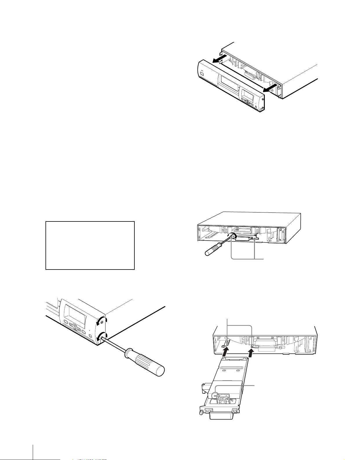
両側のネジをゆるめ、矢印の方向に平行に引くと、
フロントパネルが外れます。
S
T
A
N
D
B
Y
M
EN
U
ER
E
N
RO
TE
R
R
C
AN
C
EL
ホットスワップの場合は、選択した Drive の LED
が点滅していることを確認してください。
8
Drive1(右側のドライブ)を交換するときは、右側
の Drive の LED が点滅していることを確認してか
ら(ホットスワップの場合)、右端と中央の取り付け
ネジ 2 本をゆるめ、交換する。
9
Drive2(左側のドライブ)を交換するときは、左側
の Drive の LED が点滅していることを確認してか
ら(ホットスワップの場合)、以下のように行う。
1 Drive 1(R)の左側のネジをゆるめる。
Hot Swap 12:34
Drive D2
[ENTER] to activate
7
LCD の画面が消えた後、フロントパネル両側面のネ
ジをゆるめる。
M
E
N
U
E
E
R
N
R
T
O
E
R
R
C
A
N
C
E
L
取り付けネジ
2 図のようにして、スロットのレールに AIT ドライ
ブをのせ、奥まで押し込む。
しっかりと奥まで押し込んでください。
ホットスワップの場合は、Drive の LED が点滅
することを確認してください。
スロットレール
LED 窓
AIT ドライブを取り付ける
4
Page 5
10
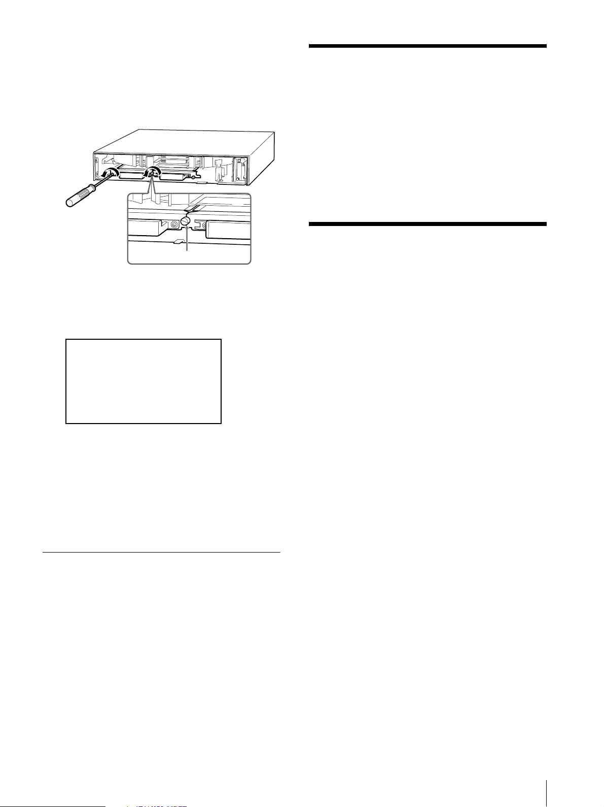
AIT ドライブのネジを締める。
中央のネジは、両方の AIT ドライブを止めていま
す。Drive1 と Drive2 の両方に AIT ドライブを入
れた場合は、図のように、両方の取り付け板がきち
んと合うまでドライブを押し込んでから、ネジを締
めてください。
取り付け板を合わせる
11
フロントパネルを元に戻す。
12
[ENTER to activate]が表示されたら、フロントパ
ネルのネジを確実に締め、[ENTER]ボタンを押す。
Hot Swap 12:34
Drive D2
Drive a Screw in?
[ENTER] to activate
13
初期化が完了した後(LCD の Initializing のメッセー
ジが消え、メニュー画面に変わった後)、
[CANCEL]ボタンを 2 回押して、ステータス表示
に戻す。
SCSI ID を設定する
AIT ドライブを取り付けたら、必要に応じて AIT ドライ
ブの SCSI ID を設定してください。
工場出荷時の SCSI ID の設定は、次のとおりです。
・ ライブラリー: 0
・ テープドライブ 1 : 1
・ テープドライブ 2 : 2
SCSI ID の設定方法については、AIT ライブラリーの取
扱説明書を参照してください。
AIT ライブラリーの F/W
バージョンを確認する
AIT ドライブを取り付けたら、ライブラリーの F/W バー
ジョンを確認してください。
AIT ドライブキットが SDX-1100V/L(AIT-5 ドライブ)
の場合、ライブラリーの F/W バージョンは「0206」以
降が必要です。
AIT ドライブキットが SDX-900V/L(AIT-4 ドライブ)
の場合、ライブラリーの F/W バージョンは「0203」以
降が必要です。
AIT ドライブキットが SDX-800V/L(AIT-3Ex ドライ
ブ)の場合、ライブラリーの F/W バージョンは「0204」
以降が必要です。
ライブラリーの最新 F/W は下記のサイトにアクセスして
入手し、アップデートを実施してください。
http://www.sony.co.jp/tapestreamer/
14
ステータス表示で、AIT ドライブの状態が実線で表
示されていることを確認する。
電源を切って行う場合
1
AIT ドライブを用意する。
ビニールやテープなどの梱包材を取り除いてくださ
い。
2
本機の電源を切る。
フロントパネルのスタンバイスイッチをオフにして
から、背面の電源スイッチで電源を切ってください。
3
「ホットスワップで行う場合」 (3 ページ)の手順 7 か
ら 11 を行う。
4
電源を入れる。
SCSI ID を設定する / AIT ライブラリーの F/W バージョンを確認する
5
Page 6

Table of Contents
Introduction
Introduction ........................................................... 6
Checking the Package Contents ........................... 7
Installing an AIT Drive ......................................... 7
When Performing a Hot Swap ........................... 7
When Turning Off the Power ............................. 9
Setting the SCSI ID ............................................... 9
Checking the Version of the AIT Library
Firmware ................................................................ 9
For details on replacing the AIT drive, contact your
nearest Sony Service Support Center. (Charges apply)
The inside of the AIT Library contains precision
components. Therefore, damage may result if you do not
install and remove the expansion drive in the correct
manner. In the event of damage, a charge will be
assessed for repair
The AIT Drive Kit can be housed and used in the AIT
library. Because the AIT drive supports hot swapping,
AIT drives can be added or exchanged while the power
is on.
There are two different types of AIT Drive Kits. When
using two AIT drives in the same AIT library, make sure
that both drives are of the same format.
• ACY-DR162/A5VL (SDX-1100V/L: for AIT-5 Drive,
left side)
• ACY-DR162/A5VR (SDX-1100V/L: for AIT-5 Drive,
right side)
• ACY-DR162/A4VL (SDX-900V/L: for AIT-4
V Drive, left side)
• ACY-DR162/A4VR (SDX-900V/L: for AIT-4
V Drive, right side)
• ACY-DR162/A3XL (SDX-800V/L: for AIT-3Ex
Drive, left side)
• ACY-DR162/A3XR (SDX-800V/L: for AIT-3Ex
Drive, right side)
• ACY-DR162/A3L (SDX-700C/L: for AIT-3 Drive,
left side)
• ACY-DR162/A3R (SDX-700C/L: for AIT-3 Drive,
right side)
• ACY-DR162/A3VL (SDX-700V/L: for AIT-3
V Drive, left side)
• ACY-DR162/A3VR (SDX-700V/L: for AIT-3
V Drive, right side)
• ACY-DR162/A2L (SDX-500C/L: for AIT-2 Drive,
left side)
• ACY-DR162/A2R (SDX-500C/L: for AIT-2 Drive,
right side)
• ACY-DR162/A1L (SDX-400C/L: for AIT-1 Drive,
left side)
• ACY-DR162/A1R (SDX-400C/L: for AIT-1 Drive,
right side)
© 2001 Sony Corporation. All rights reserved.
Trademarks
• Advanced Intelligent Tape is a trademark of Sony Corporation in this country, other countries, or both.
• Other product names are trademarks or registered trademarks of their respective owners in this country, other
countries, or both.
6
Introduction
Page 7
Checking the Package
Contents
After opening the package, make sure that all of the
following items are present. Contact your dealer if
anything is missing.
• AIT drive (1)
• SCSI cable (1)
• Operating instructions (this manual) (1)
*
Only with the ACY-DR162/A5VL,
ACY-DR162/A4VL, ACY-DR162/A3XL,
ACY-DR162/A3L, ACY-DR162/A3VL,
ACY-DR162/A2L, and ACY-DR162/A1L.
*
When Performing a Hot Swap
Use the control panel’s Hot Swap Menu to specify the
element address for the slot (drive 1 (R) or drive 2 (L))
before installing the AIT drive.
1
Prepare an AIT drive.
Remove all packing materials from the drive,
including the vinyl bag, tape, etc.
2
At the status display, press the [MENU] button for
two seconds.
3
Press the V button seven times and select “8.
Password”, then hold down the [MENU] button and
press the V button. “Manual operation” appears.
Installing an AIT Drive
Install the AIT drive in the drive slot (drive 1 (R) or drive
2 (L)).
• For drive 1 (R) slot, you can install the
ACY-DR162/A5VR, ACY-DR162/A4VR,
ACYDR162/A3XR, ACY-DR162/A3R,
ACYDR162/A3VR, ACY-DR162/A2R, or
ACY-DR162/A1R.
• For drive 2 (L) slot, you can install the
ACY-DR162/A5VL, ACY-DR162/A4VL,
ACYDR162/A3XL, ACY-DR162/A3L,
ACYDR162/A3VL, ACY-DR162/A2L, or
ACY-DR162/A1L.
To install the AIT drive, perform the following
procedure.
• If you will be doing a hot swap, specify the drive slot
(drive 1 (R) or drive 2 (L)) from the control panel
before installing the AIT drive.
• If you will not be doing a hot swap, turn off the AIT
library before installing the AIT drive.
• For installation instructions, contact Sony Service
Support Center. (Charges apply.)
Manual Operation
1.Hot Swap
2.Life Information
3.Error Information
4.Sencer Information
5.Log
6.Demonstration
4
Select “1. Hot Swap,” then press the [ENTER]
button.
“Drive D1” appears. (Depending on your drive,
“Drive 1” may appear instead of “D1”.)
Hot Swap 12:34
Drive D1
12:34
GB
This procedure requires a standard screwdriver.
Caution
• Electrostatic charges that build up on your body can
damage the components. Before handling the drive,
touch the metal chassis of the AIT Library. When the
front panel is open, do not touch any components
other than those that must be replaced.
• Do not install drives that of differing formats.
Checking the Package Contents / Installing an AIT Drive
7
Page 8
5
Press the v or V button to display “D2” and “D1 &
D2”, then select the drive slot where the AIT drive
to replace and press the [ENTER] button.
(Depending on your drive, “Drive 2” may appear
instead of “D2” and “Drive 1&2” instead of
“D1&D2”.)
The illustration below shows an example with
Drive 2 selected.
• Drive 1 is the drive slot on the right, and you can
install the ACY-DR162/A5VR,
ACY-DR162/A4VR, ACY-DR162/A3XR,
ACY-DR162/A3R, ACY-DR162/A3VR,
ACY-DR162/A2R, or ACY-DR162/A1R in this
slot.
• Drive 2 is the drive slot on the left, and you can
install the ACY-DR162/A5VL,
ACY-DR162/A4VL, ACY-DR162/A3XL,
ACY-DR162/A3L, ACY-DR162/A3VL,
ACY-DR162/A2L, or ACY-DR162/A1L in this
slot.
• Make sure that both drives (left and right) are of
the same format.
6
When “[ENTER] to activate?” appears, press the
[ENTER] button.
Hot Swap 12:34
Drive D2
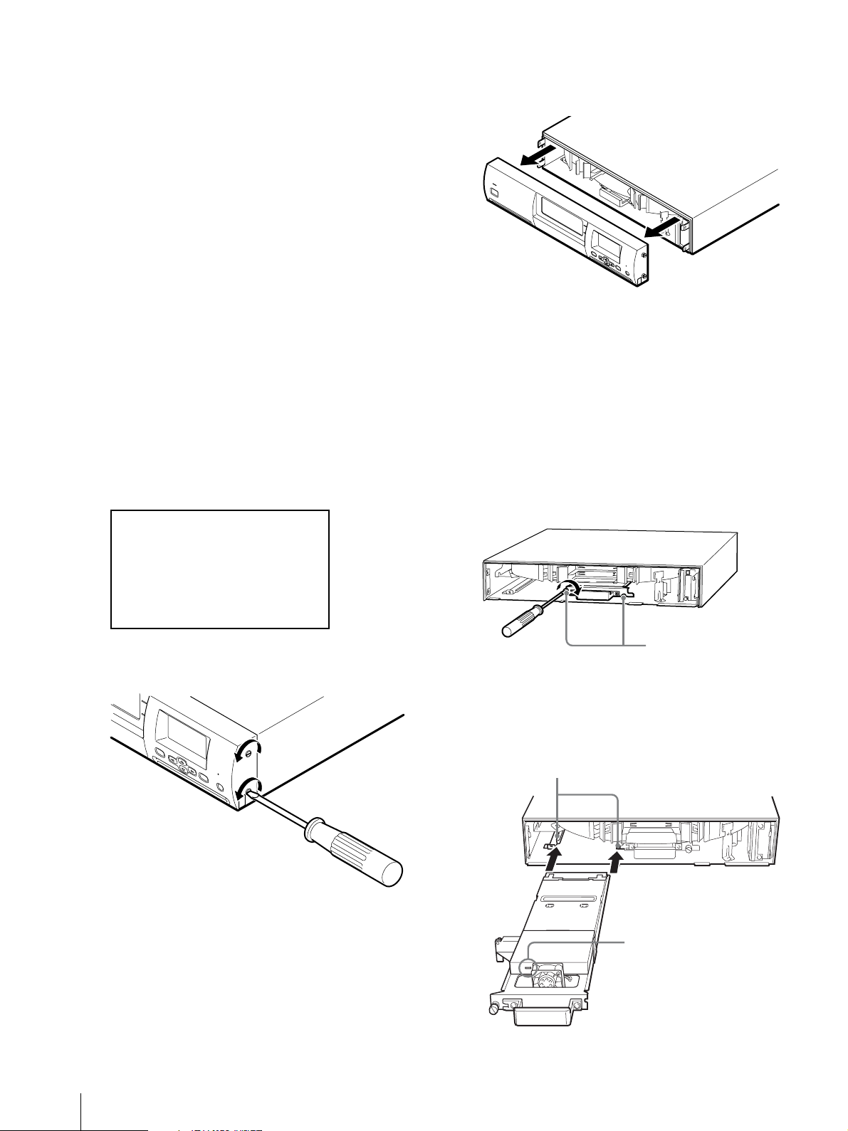
Remove the screws on both sides of the front panel
and pull it horizontally in the direction of the arrow
to remove it.
S
T
A
N
D
B
Y
ME
N
U
E
EN
R
RO
T
ER
R
C
AN
C
EL
When using Hot Swap, make sure that the LED of
the drive that you selected is blinking.
8
When replacing Drive 1 (the one on the right), first
make sure that the right-hand drive LED is blinking
(when using Hot Swap), then loosen the middle and
right screws, and finally replace the drive.
9
When replacing Drive 2 (the one on the left), make
sure that the left-hand drive LED is blinking (when
using Hot Swap), and then replace the drive as
explained below.
1
Remove the screw on the left side of drive 1 (R).
[ENTER] to activate
7
After the LCD screen disappears, remove the
screws on both sides of the front panel.
M
E
N
U
E
E
R
N
R
T
O
E
R
R
C
A
N
C
E
L
Screws
2 Fit the AIT drive onto the rails of the AIT drive
slot as shown in the diagram, and push the AIT
drive slot in as far as it will go.
When using Hot Swap, make sure that the drive
LED is blinking.
Slot rails
LED hole
8
Installing an AIT Drive
Page 9
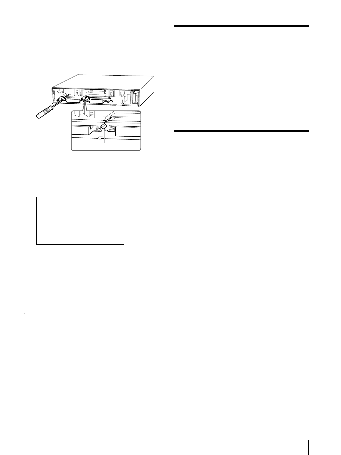
10
Tighten the AIT drive screws.
The middle screw serves as a fastener for both AIT
drives. When an AIT drive is installed in both Drive
1 and Drive 2:
Push the AIT drive into the slot until both of the
installation boards are level as shown in the
diagram, then tighten the screws.
Setting the SCSI ID
After installing an AIT drive, set the SCSI ID for the
AIT drive as necessary.
The factory settings for the SCSI IDs of these devices
are as follows:
• Library: 0
• Tape drive 1: 1
• Tape drive 2: 2
For details on how to set the SCSI ID, refer to the
Operating Instructions for the AIT library.
Installation boards
11
Replace the front panel.
12
When “[ENTER] to activate?” appears, make sure
that the front panel is securely fastened, then press
the [ENTER] button.
Hot Swap 12:34
Drive D2
Drive a Screw in?
[ENTER] to activate
13
After initialization is complete (the Initializing
message disappears from the LCD and the menu
screen appears), press the [CANCEL] button twice
to return to the status display.
14
In the status display, check that the AIT drive
representations appear as solid lines.
Checking the Version of
the AIT Library Firmware
After you have installed the AIT drive, check the version
of the library firmware.
If you are using the AIT Drive Kit SDX-1100V/L (for
AIT-5 Drive), the library firmware version should be
0206 or later.
If you are using the AIT Drive Kit SDX-900V/L (for
AIT-4 Drive), the library firmware version should be
0203 or later.
If you are using the AIT Drive Kit SDX-800V/L (for
AIT-3Ex Drive), the library firmware version should be
0204 or later.
Visit the following web site to download the latest
version of the library firmware, and perform an update:
http://www.sony.co.jp/en/Products/TS/
When Turning Off the Power
1
Prepare an AIT drive.
Remove all packing materials from the drive,
including the vinyl bag, tape, etc.
2
Turn off the power.
Turn off the standby switch on the front panel, then
turn off the power switch at the rear of the AIT
library.
3
When doing a hot swap, perform the steps 7
through 11 on page 8.
4
Turn on the power.
Setting the SCSI ID / Checking the Version of the AIT Library Firmware
9
Page 10

Page 11

Page 12
Printed in Japan
 Loading...