

Sony A-700T Service Manual
SERVICE MANUAL
A-700T
N. Hemisphere Model
Chassis No.SCC-L10E-A
A-700T
Picture Tube
Video image area
Logical resolution
Physical resolution
SPECIFICATIONS
0.25 mm aperture grill pitch
17 inches measured diagonally
90-degree deflection
(15.9" maximum viewing image)
Approx. 327 x 241 mm (w/h)
7/8
1/2
x 9
(12
Horizontal: Max. 1280 dots
Vertical: Max. 1024 lines
Horizontal: Max. 1024 dots
Vertical: Max. 768 lines
inches)
X2F
Standard image area
Deflection frequency
AC input voltage / current
Dimensions
Mass
Design and specifications are subject to change without notice.
Approx. 312 x 234 mm (w/h)
(12
Horizontal: 30 to 70 KHz
Vertical: 50 to 120 Hz
100 to 120 V , 50-60 Hz, 1.8 A (max.)
220 to 240 V, 50-60 Hz, 1.0 A
406 x 426.5 x 451 mm (w/h/d)
(16 x 16
Approx. 18.5 kg (40lbs 13oz)
CHASSIS
3/8
1/4
x 9
inches)
7/8
7/8
x 17
inches)
COLOR COMPUTER DISPLAY
— 1 —
A-700T
POWER SAVING FUNCTION
This monitor meets the power saving guidelines set
by the EPA Energy Star Program as well as the more
stringent TC092 guidelines (NUTEK). It is capable of
reduced power consumption when used with a computer equipped with Display Power Management Signaling (DPMS). By sensing the absence of the sync
signal coming from the computer, it will reduce the
CAUTION:
The Power Saving function will automatically put the monitor into Active-off state
if the power switch is turned on without
any video signal input. Once the horizontal and vertical syncs are sensed, the monitor will automatically return to its Normal
operation state.
power consumption as follows:
State Power Required u Power indicator POWER SAVING
consumption resumption time indicator
1
2
3
4
Normal Operation
Stand-by
1st step of power saving)
Suspend
(2nd step of power saving)
Active-off
(3rd step of power saving)
< 110W green on off
< 15W approx. 3 sec. green on orange on
< 15W approx. 3 sec. green on orange on
< 8W approx. 10 sec. off orange on
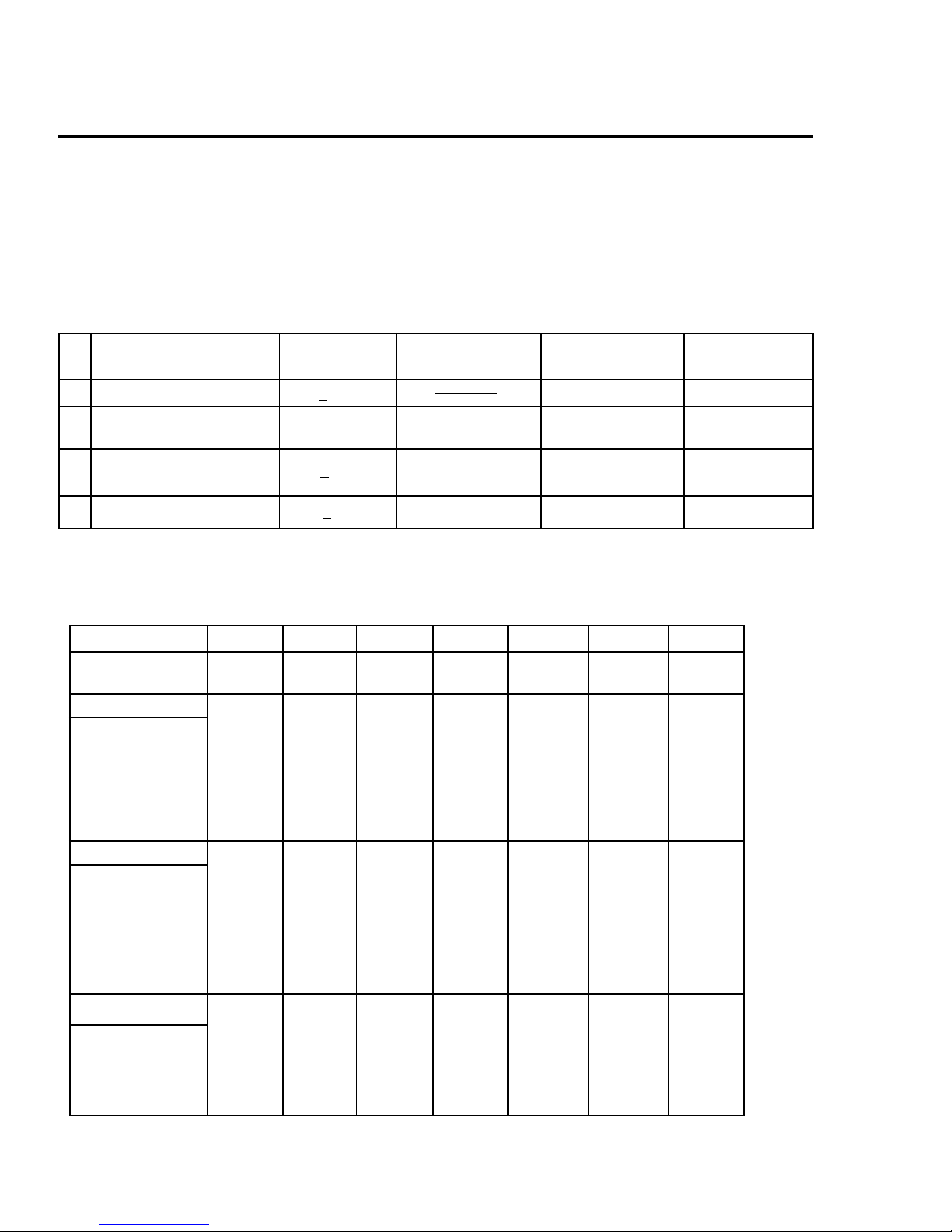
TIMING SPECIFICATION
MODE 1 2 3 4 5 6 7
Resolution(H x V)
Dot Clock(MHz)
HORIZONTAL
Hor. Freq. (kHz)
H-Total
H-Blanking
H-Front Porch
H-Sync.
H-Back Porch
H-Active
(µsec)
VERTICAL
Ver. Freq. (Hz)
V-Total
V-Blanking
V-Front Porch
V-Sync.
V-Back Porch
V-Active
(lines)
640 x 480
25.175
31.469
31.778
6.356
0.636
3.813
1.907
25.422
59.940
525
45
10
33
480
2
800 x 600
49.500
46.875
21.333
5.172
0.323
1.616
3.232
16.162
75.000
625
25
21
600
1
3
800 x 600
56.250
53.674
18.631
4.409
0.569
1.138
2.702
14.222
85.061
631
31
27
600
1
3
832 x 624
57.283
49.725
20.111
5.586
0.559
1.117
3.910
14.524
74.550
667
43
39
624
1024 x 768
1
3
78.750
60.023
16.660
3.657
0.203
1.219
2.235
13.003
75.029
800
32
28
768
1280 x 1024
108.000
63.981
15.630
11.852
60.020
1
3
3.778
0.444
1.037
2.296
1066
42
38
1024
1024 x 768
1
3
94.500
68.677
14.561
3.725
0.508
1.016
2.201
10.836
84.997
808
40
1
3
36
768
SYNC.
Int(G)
Ext (H/V)/Polarity
Ext (CS)/Polarity
Int / Non Int Non Int Non Int Non Int Non Int Non Int Non Int Non Int
No
Yes -/ No
No
Yes +/+
No
No
Yes +/+
No
— 2 —
No
Yes -/ No
No
Yes +/+
No
No
Yes +/+
No
No
Yes +/+
No
SAFETY CHECK-OUT
(US Model only)
A-700T
After correcting the original service problem, perform
the following safety checks before releasing the set to the
customer:
1. Check the area of your repair for unsoldered or
poorly-soldered connections. Check the entire board
surface for solder splashes and bridges.
2. Check the interboard wiring to ensure that no wires
are “pinched” or contact high-wattage resistors.
3. Check that all control knobs, shields, covers, ground
straps, and mounting hardware have been replaced.
Be absolutely certain that you have replaced all the
insulators.
4. Look for unauthorized replacement parts,
particularly transistors, that were installed during
a previous repair. Point them out to the customer
and recommend their replacement.
5. Look for parts which, though functioning, show
obvious signs of deterioration. Point them out to
the customer and recommend their replacement.
6. Check the line cords for cracks and abrasion.
Recommend the replacement of any such line cord
to the customer.
7. Check the B+ and HV to see if they are specified
values. Make sure your instruments are accurate;
be suspicious of your HV meter if sets always have
low HV.
8. Check the antenna terminals, metal trim,
“metallized" knobs, screws, and all other exposed
metal parts for AC Leakage. Check leakage as
described below.
To Exposed Metal
Parts on Set
LEAKAGE TEST
The AC leakage from any exposed metal part to earth ground
and from all exposed metal parts to any exposed metal part having
a return to chassis, must not exceed 0.5 mA (500 microampere).
Leakage current can be measured by any one of three methods.
1. A commercial leakage tester, such as the Simpson 229 or
RCA WT-540A. Follow the manufacturers' instructions to
use these instructions.
2. A battery-operated AC milliammeter. The Data Precision
245 digital multimeter is suitable for this job.
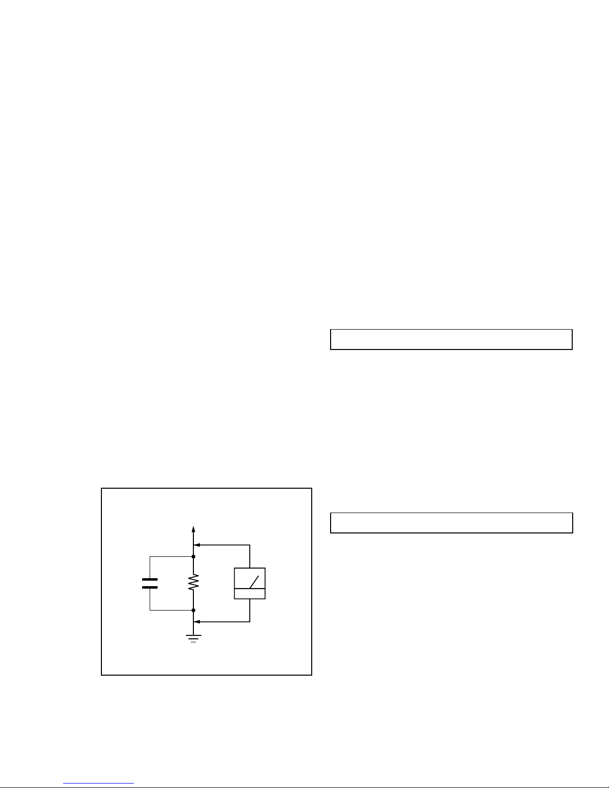
3. Measuring the voltage drop across a resistor by means of
a VOM or battery-operated AC voltmeter. The "limit"
indication is 0.75 V, so analog meters must have an accurate
low voltage scale. The Simpson's 250 and Sanwa
SH-63Trd are examples of passive VOMs that are suitable.
Nearly all battery operated digital multimeters that have a
2V AC range are suitable. (See Fig. A)
WARNING!!WARNING!!
WARNING!!
WARNING!!WARNING!!
NEVER TURN ON THE POWER IN A CONDITION IN WHICH THE
DEGAUSS COIL HAS BEEN REMOVED.
SAFETY-RELATED COMPONENT WARNING!!
COMPONENTS IDENTIFIED BY SHADING AND MARK ¡ ON
THE SCHEMATIC DIAGRAMS, EXPLODED VIEWS AND IN THE
PARTS LIST ARE CRITICAL FOR SAFE OPERATION. REPLACE
THESE COMPONENTS WITH SONY PARTS WHOSE PART
NUMBERS APPEAR AS SHOWN IN THIS MANUAL OR IN
SUPPLEMENTS PUBLISHED BY SONY . CIRCUIT ADJUSTMENTS
THAT ARE CRITICAL FOR SAFE OPERATION ARE IDENTIFIED
IN THIS MANUAL. FOLLOW THESE PROCEDURES WHENEVER
CRITICAL COMPONENTS ARE REPLACED OR IMPROPER
OPERATION IS SUSPECTED.
AVERTISSEMENT!!
0.15 µF
Fig. A. Using an AC voltmeter to check AC leakage.
1.5 k
Ω
Earth Ground
AC
Voltmeter
(0.75 V)
NE JAMAIS METTRE SOUS TENSION OUAND LA BOBINE DE
DEMAGNETISATION EST ENLEVEE.
ATTENTION AUX COMPOSANTS RELATIFS A LA
SECURITE!!
LES COMPOSANTS IDENTIFIES P AR UNE TRAME ET PAR UNE
MARQUE ¡ SUR LES SCHEMAS DE PRINCIPE, LES VUES
EXPLOSEES ET LES LISTES DE PIECES SONT D'UNE
IMPORTANCE CRITIQUE POUR LA SECURITE DU
FONCTIONNEMENT. NE LES REMPLACER QUE PAR DES
COMPOSANTS SONY DONT LE NUMERO DE PIECE EST
INDIQUE DANS LE PRESENT MANUEL OU D ANS DES SUPPLEMENTS PUBLIES PAR SONY. LES REGLAGES DE CIRCUIT
DONT L'IMPORTANCE EST CRITIQUE POUR LA
SECURITE DU FONCTIONNEMENT SONT IDENTIFIES DANS
LE PRESENT MANUEL. SUIVRE CES PR OCEDURES LORS DE
CHAQUE REMPLA CEMENT DE COMPOSANTS CRITIQUES, OU
LORSQU'UN MAUVAIS FONTIONNEMENT SUSPECTE
— 3 —
.

A-700T
TABLE OF CONTENTS
Section Title Page
1. GENERAL ................................................................................... 5
2. DISASSEMBLY
2-1. Cabinet Removal ............................................................8
2-2. Service Position .............................................................. 8
2-3. D Board Removal ........................................................... 8
2-4. Picture Tube Removal ................................................... 9
3. SAFETY RELATED ADJUSTMENT.................................10
4. ADJUSTMENTS ........................................................................11
5. DIAGRAMS
5-1. Block Diagram ................................................................15
5-2. Circuit Boards Location ................................................. 18
5-3. Schematic Diagrams and Printed Wiring Boards ......18
1. D Board - Schematic Diagram .................................19
2. A Board - Schematic Diagram ................................. 23
5-4. Semiconductors ..............................................................27
6. EXPLODED VIEWS
6-1. Chassis ............................................................................ 29
6-2. Packing Materials .......................................................... 30
7. ELECTRICAL PARTS LIST ................................................ 31
— 4 —
— 5 —
A-700T
4
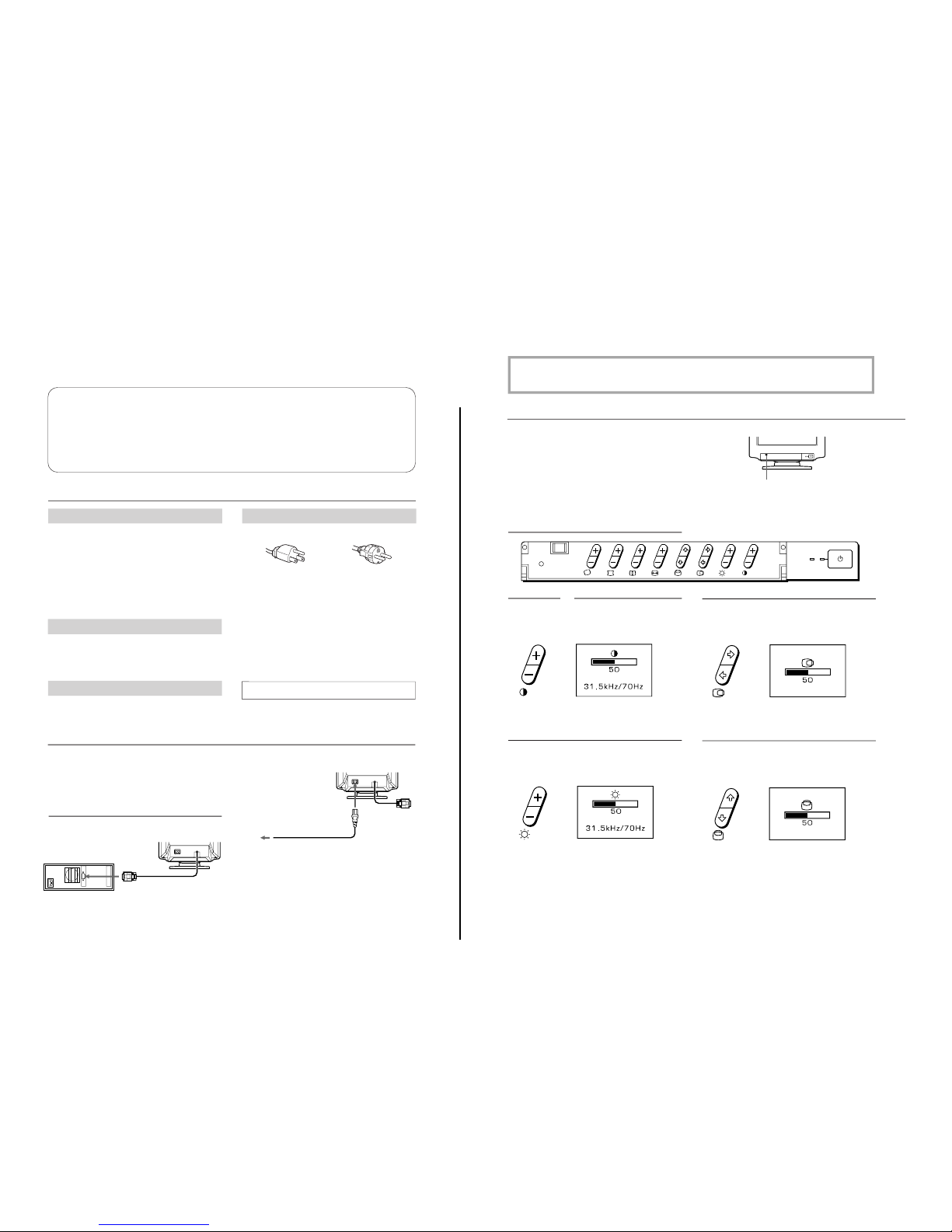
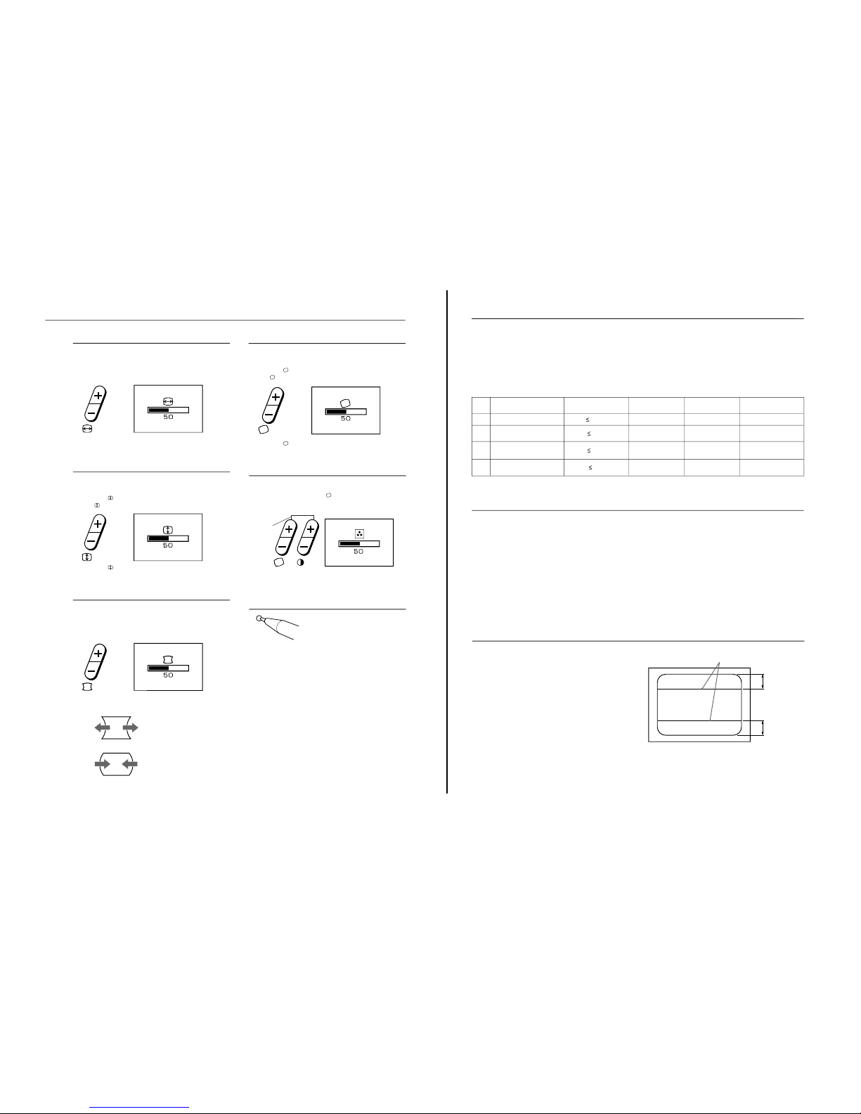
Adjustments
A number of digital controls are provided to allow you to
optimize the display parameters to your preferences.
You can adjust the picture to your preferences by following
the procedure described below.
You can adjust all items on the OSD (On Screen Display).
POWER
SAVING
Push this part to open the control panel cover.
p Adjustments will be stored automatically.
p The OSD automatically disappears 3 seconds after you
release the buttons.
Control Panel
Contrast
The adjustment data becomes the common setting for all
input signals.
1
Press the >+/– button.
The > OSD (On Screen Display) appears.
2
Press the >+/– button to adjust picture contrast.
+.... for more contrast
– ....for less contrast
Horizontal centering
The adjustment data becomes the unique setting for the
input signal received.
1
Press the S∫/ı button.
The S OSD (On Screen Display) appears.
2
Press the S∫/ı button.
∫ ... to move right
ı ... to move left
Brightness
The adjustment data becomes the common setting for all
input signals.
1
Press the ¨+/– button.
The ¨ OSD (On Screen Display) appears.
2
Press the ¨+/– button to adjust picture brightness.
+.... for more brightness
– ....for less brightness
Vertical centering
The adjustment data becomes the unique setting for the
input signal received.
1
Press the s◊/√ button.
The s OSD (On Screen Display) appears.
2
Press the s◊/√ button.
◊ ... to move up
√ ... to move down
POWER
SAVING
RESET
3
EN
Installation
• Prevent internal heat buildup by allowing adequate air
circulation. Do not place the unit on surfaces (rugs,
blankets, etc.) or near materials (curtains, draperies) that
may block the ventilation holes.
• Do not install the unit near heat sources such as radiators
or air ducts, or in a place subject to direct sunlight,
excessive dust, mechanical vibration or shock.
• Do not place the unit near equipment that generates
magnetism, such as a converter or high-voltage power
lines.
Maintenance
Clean the cabinet, glass panel, and controls with a soft cloth,
lightly moistened with a mild detergent solution. Do not use
any type of abrasive pad, scouring powder, or solvent, such
as alcohol or benzine.
Transportation
When you transport this monitor for repairing or shipping,
use the original carton box and packing materials.
Table of Contents
Precautions ............................................................................... 3
Getting Started ......................................................................... 3
Adjustments.............................................................................. 4
Power Saving Function........................................................... 6
Plug and Play ........................................................................... 6
Damper Wire ..........................................................................6
Use of the Tilt-Swivel............................................................ 7
Specifications ..........................................................................7
Troubleshooting..................................................................... 7
Precautions
Warning on Power Connection
• Use the supplied power cord.
Before using this monitor, make sure that the following
items are included in your package:
the monitor, power cord and this operating instruction
manual.
This monitor will sync to platforms running at horizontal
frequencies between 30 and 70 kHz.
Connecting the Computer
Step 1: With the computer switched off, attach the video
signal cable to the video output.
Step 2: Attach the power cord to the monitor and then to
the power outlet.
Step 3: Turn on the monitor and computer.
Step 4: If necessary, adjust the user controls according to
your personal preference.
The installation is complete.
Computer
to the video output
Power cord (supplied)
to the power
outlet
Getting Started
for 220 to 240 V AC
for 100 to 120 V AC
For the customers in U.S.A.
If you do not do this, this monitor will not conform to
mandatory FCC standards.
• Before disconnecting the power cord, wait for at least
30 seconds after turning off the power switch to allow for the
discharging of static electricity on the CRT display surface.
• After the power has been turned on, the CRT is
demagnetized for approximately 5 seconds. This
generates a strong magnetic field around the bezel, which
may affect the data stored on magnetic tape or disks near
the bezel. Place such magnetic recording equipment and
tapes/disks at a distance from this unit.
The socket-outlet shall be installed near the equipment
and shall be easily accessible.
The instructions given here are partial abstracts from the Operating Instruction
Manual. The page numbers shown reflect those of the Operating Instruction Manual.
SECTION 1
GENERAL
— 6 —
A-700T
5
EN
RESET
Horizontal size
The adjustment data becomes the unique setting for the
input signal received.
1
Press the Å+/– button.
The Å OSD (On Screen Display) appears.
2
Press the Å+/– button.
+.... to enlarge
– .... to diminish
Vertical size
The adjustment data becomes the unique setting for the
input signal received.
1
Press the +/– button.
The
OSD (On Screen Display) appears.
2
Press the
+/– button.
+.... to enlarge
– .... to diminish
2
Press the d+/– button.
+ ... to expand the picture sides
– ... to diminish the picture sides
Pincushion
The adjustment data becomes the unique setting for the
input signal received.
1
Press the d+/– button.
The d OSD (On Screen Display) appears.
Rotation
The adjustment data becomes the common setting for all
input signals.
1
Press the +/– button.
The
OSD (On Screen Display) appears.
2
Press the +/– button.
+.... to rotate clockwise
– .... to rotate counterclockwise
Resetting
• Press the RESET button to recall the
factory settings for brightness, contrast,
pincushion, horizontal and vertical size,
and center for the mode currently in
use.
• Press and hold the RESET button for 2
seconds to recall factory settings for all
adjustments in all modes.
Color Adjustment
This adjustment is common to all input signals received.
1
Press the + buttons of the
Raster Rotation and the >
Contrast simultaneously. The OSD (On Screen Display)
appears.
2
Press the >+/– button.
+.... for higher color temperature
– .... for lower color temperature
Press the +
buttons
simultaneously
6
Required
resumption time
—
approx. 3 sec.
approx. 3 sec.
approx. 10 sec.
State
Normal operation
Stand-by
(1st step of power saving)
Suspend
(2nd step of power saving)
Active-off
(3rd step of power saving)
Plug and Play
Damper Wire
Using a white background, very thin horizontal stripes on
the screen are visible as shown right. These stripes are the
damper wires. These wires are attached to the aperture
grille inside the Trinitron tube and are there to damp
vibrations of the aperture grille in order to prevent them
from influencing the picture quality.
Approx. 6 cm
Approx. 6 cm
Damper wire
Power Saving Function
This monitor meets the power-saving guidelines set by the
International
E
nergy Star Program as well as the more
stringent NUTEK 803299 (TCO92) guidelines. It is capable
of reduced power consumption when used with a computer
equipped with Display Power Management Signaling
(DPMS). By sensing the absence of the sync signal coming
from the computer, it will reduce the power consumption as
follows:
CAUTION: The Power Saving function will automatically
put the monitor into Active-off state if the
power switch is turned on without any video
signal input. Once the horizontal and vertical
syncs are sensed, the monitor will
automatically return to its Normal operation
state.
Power consumption
110 W
15 W
15 W
8 W
u Power indicator
green on
green on
green on
off
POWER SAVING
indicator
off
orange on
orange on
orange on
1
2
3
4
This monitor complies with the DDC
TM
1, DDC2B and
DDC2AB which are the Display Data Channel (DDC)
standards of VESA.
When a DDC1 host system is connected, the monitor
synchronizes with the V. CLK in accordance with the VESA
standards and outputs the EDID (Extended Display
Identification Data) to the data line.
When a DDC2B or DDC2AB host system is connected, the
monitor automatically switches to each communication.
DDC
TM
is a trademark of Video Electronics Standard
Association.
• Your monitor operates according to the VESA DDC Level
2AB. Only computers that support the same guidelines
and operate at the same or higher level can make use of
this feature.
• If your computer does not support the relevant
guidelines, you can still use your monitor and computer.
You may need to specify manually the appropriate
resolution in the computer.
• The highest resolution selected automatically may not
give the best result. In that case select the most suitable
resolution manually in the computer.
— 7 —
A-700T
8
If the message of “OUT OF
SCAN RANGE”
appears on the screen
Picture is scrambled
Color is not uniform
Screen image is not
centered or sized properly
Picture is fuzzy
Picture bounces or has
wavy oscillations
A fine horizontal line
(wire) is visible
Screen image is tilted
Edges of the image are
curved.
Wavy or elliptical (moire)
pattern is visible
Symptom
Troubleshooting
Check these items
* The Auto-degauss function demagnetizes the metal frame of the CRT in order to obtain a
neutral field for uniform color reproduction. If a second degauss cycle is needed, allow a
minimum interval of 20 minutes for the best result.
** Trinitron
is a registered trademark of Sony Corporation.
• If the problem persists, call your authorized dealer from a location near your monitor.
• Note the model name and the serial number of your monitor. Also note the make and name of your computer and video
board.
• Check that the video sync signal is specified for the monitor.
• Check your graphics board manual for the proper monitor setting on your monitor.
• Check this manual and confirm that the graphics mode and the frequency at which you
are trying to operate is supported. Even within the proper range, some video boards
may have a sync pulse that is too narrow for the monitor to sync correctly.
• Trip the u power switch once to activate the Auto-degauss cycle*.
• Adjust centering or size (pages 4, 5).
• Some video modes do not fill the screen to the edge of the monitor. There is no single
answer to solve the problem. There is tendency to have this problem on higher refresh
timings.
• Adjust the Contrast and Brightness controls (page 4). Several brands of SVGA boards
have an excessive video output level which creates a fuzzy picture at max contrast.
• Trip the u power switch once to activate the Auto-degauss cycle*.
• Move electrical (magnetic) devices that may be creating electrical interference away
from the monitor.
• If you have another monitor close to this monitor, increase the distance between them to
reduce the interference.
• Your office may have electric power wiring behind the wall. Move the monitor away
from the wall.
• This wire stabilizes the vertically striped Aperture Grille. This Aperture Grille allows
more light to pass through to the screen giving the Trinitron
** CRT more color and
brightness.
• Trip the u power switch once to active the Auto-degauss cycle∗.
Then, adjust the Rotation (page 5).
• Adjust the Pincushion (page 5).
• Due to the relationship between resolution, monitor dot pitch, and the pitch of some
image patterns, certain screen backgrounds, especially gray, sometimes show moire.
This can only be eliminated by changing your desktop pattern.
7
EN
Check these items
• Check that the power cord is properly connected.
• Check that the u power switch is in the “on” position.
• Check that your computer power switch is in the “on” position.
• The monitor will recover when you press any key on the keyboard of the computer.
• Check that the video cable is properly connected.
• Ensure that no pins are bent or pushed in the HD15 connector of the cable.
• Check that the video card is seated completely in a proper bus slot.
• Check that the video sync signal is within that specified for the monitor.
• Use the monitor’s self-diagnosis function to check for any other problems. To use the self-
diagnosis, power down the monitor, then press and hold the u power switch until the u
(power) indicator begins to blink (after about five seconds), then the screen should turn
white and a display of three colored bars (red, green, and blue) appears in the middle of the
black display. If you observe these conditions, the monitor is working properly.
• Turn the monitor off and on. If the indicator is not flashing, the monitor is in the normal
condition.
• There is a potential monitor failure. Contact your dealer.
Symptom
No picture
If neither the u (power)
indicator nor the POWER
SAVING indicator is lit
If the POWER SAVING
indicator is lit
If the u (power) and the
POWER SAVING
indicators are both flashing
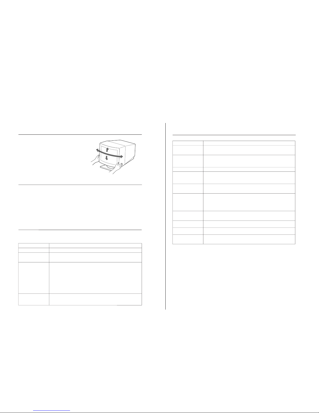
Use of the Tilt-Swivel
45°
15°
45°
With the tilt-swivel base, this unit can be adjusted to be
viewed at your desired angle within 90° horizontally and
20° vertically.
To turn the unit vertically and horizontally, hold it at its
bottom with both hands.
5°
Specifications
Picture tube 0.25 mm aperture grille pitch
17 inches measured diagonally
90-degree deflection
Viewable image size
Approx. 327 × 241 mm (w/h)
(12
7
/8 × 9
1
/2 inches)
15.9” viewing image
Resolution Horizontal: Max. 1280 dots
Vertical: Max. 1024 lines
Display picture size Approx. 312 × 234 mm (w/h)
(12
3
/8 × 9 1/4 inches)
Deflection frequency Horizontal: 30 to 70 kHz
Vertical: 50 to 120 Hz
AC input voltage/current
100 to 120 V, 50/60 Hz, 1.8 A
220 to 240 V, 50-60 Hz, 1 A
Dimensions 406 × 426.5 × 451 mm (w/h/d)
(16 × 16
7
/8 × 17 7/8 inches)
Mass Approx. 18.5 kg (40 lb 13 oz)
Design and specifications are subject to change without
notice.
T r oubleshooting
This section may help you isolate a problem and, as a result, eliminate the need to contact technical support, allowing continued
productivity.
A-700T
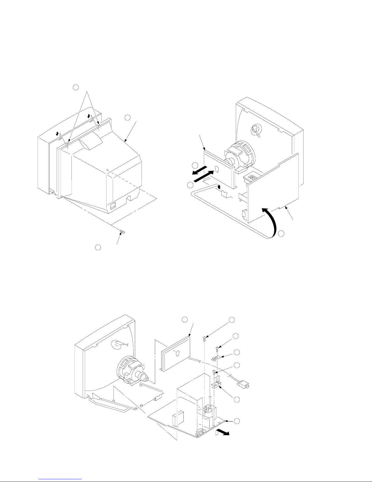
SECTION 2
DISASSEMBLY
2-1. CABINET REMOVAL 2-2. SERVICE POSITION
2
Two claws
PUSH
PUSH
1
Two screws
(BVTP 4 x 16)
3
Cabinet
A board
1
3
D board
2
2-3. D BOARD REMOVAL
— 8 —
1
A board
6
Five screws
(BVTP 3 x 12)
2
One screw
(BVTT 4 x 8)
3
Cable stopper
4
Two screws
(BVTP 3 x 12)
5
Cable bracket
7
D board
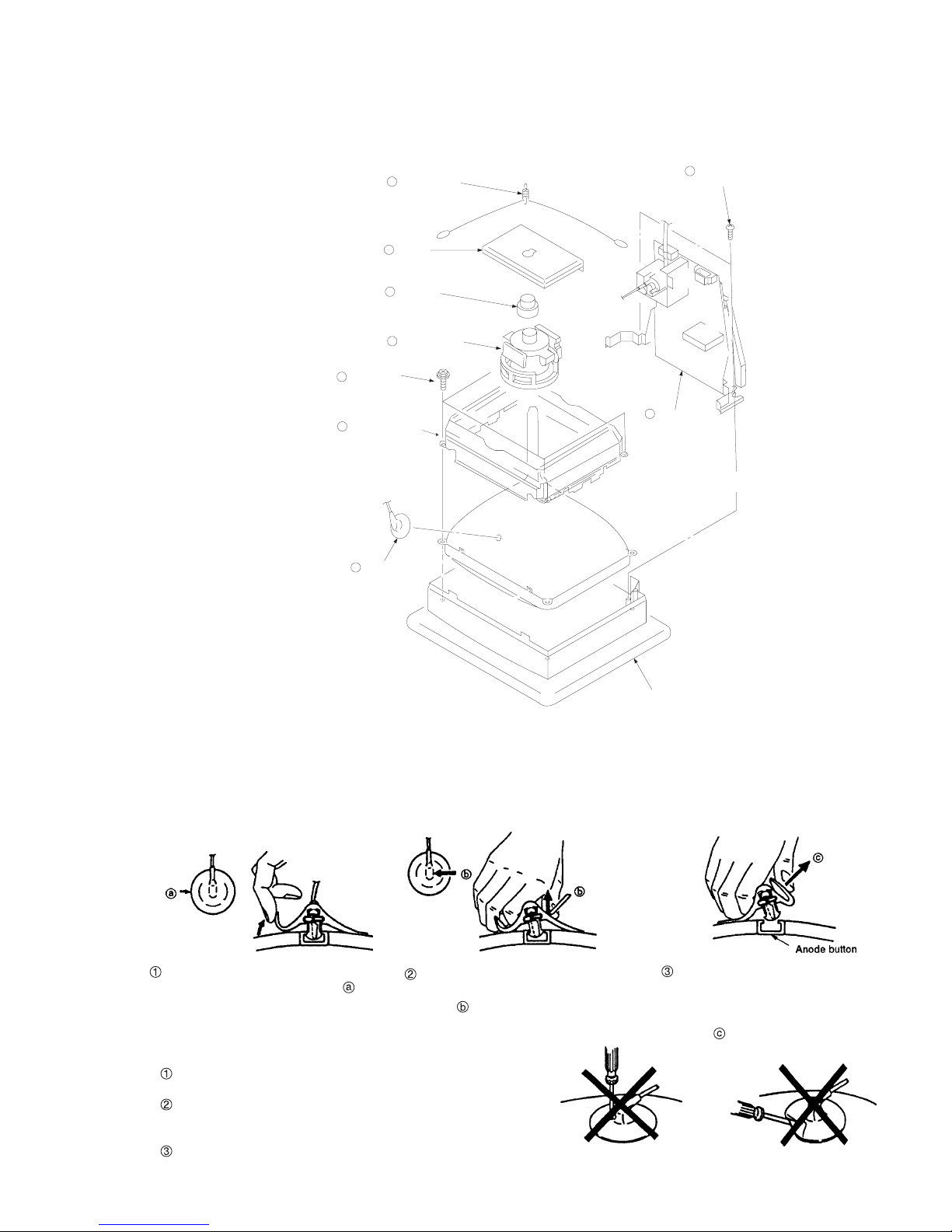
2-4. PICTURE TUBE REMOVAL
3
Four screws
(Tapping screw 5)
Picture tube shield
2
8
Demagnetization coil
7
Tension spring
6
A board
5
Neck assy
4
Deflection yoke
9
Two screws
10
Stand assy
(D board)
A-700T
(BVTP 4 x 16)
1
Anode cap
Cushion
REMOVAL OF THE ANODE-CAP
NOTE: Short circuit the anode of the picture tube and the anode cap to the metal chassis, CRT shield or carbon painted on the CRT, after
removing the anode.
REMOVAL PROCEDURES
Turn up one side of the rubber cap in
the direction indicated by arrow .
Use your thumb to pull the rubber cap
firmly in the direction indicated by
arrow .
HOW TO HANDLE AN ANODE-CAP
Do not use sharp objects which may cause damage to the surface
of the anode-cap.
Do not squeeze the rubber covering too hard to avoid damaging
the anode-cap. A material fitting called a shatter-hook terminal is
built into the rubber.
Do not force turn the foot of the rubber cover. This may cause the
shatter-hook terminal to protrude and damage the rubber.
When one side of the rubber cap sepa-
rates from the anode button, the anodecap can be removed by turning the rubber cap and pulling it in the direction of
arrow .
— 9 —
 Loading...