


ServiceTechnicalInformation
MODELNO.
Modelswith6ZG1mechanism −
SUBJECT
DATE: Dec. 15-1999
<CONTENTS>
Useofthejigimprovesserviceabilty of models with 5 CD changer.
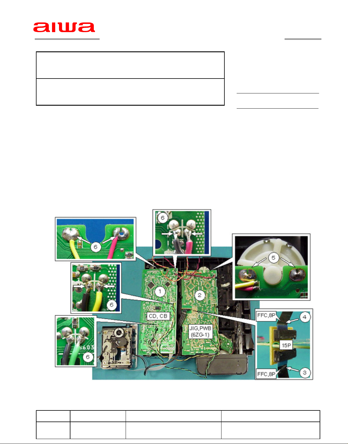
MountingproceduresandusemethodforthejigPWBisdescribebelow:
Mountingprocedure
1.RemoveCDPWBfroma6ZG1mechanism.−
2.MountthejigPWB(JIG,PWB(6ZG1))ontothe6ZG1mechanism.−−
3.PlugFFC,8PfromT-TPWBontotheconnectoronthejigPWB.(Note:Payattentionto
connectingpositionofFFC,8P,sincea15PconnectorismountedonthejigPWB.)
4.ConnectaseparatelyobtainedFFC,8P,betweenthejigPWBandCDPWB.
5.SolderMOTORpinontojigPWB.
6.Solderextensionwires(8wires)ofthejigPWBontoSWandMOTORpinsoftheCDPWB.
1/1
Usemethod
SeparateaCDC.B,etc.fromamainunitusinganextensionjigexplainedin SB # 22-96-009
andthenoperatetheunitasnormal.
Ref. PartsCode Description Remarks
−−−− − −SVJ00073010 JIG,PWB(6ZG1)
−−−− −86ZG1608010 CABLE,FFC8P