

SONY 910102 Service Manual
ServiceTechnicalInformation
MODELNO.
Modelswith4ZG-1mounted
SUBJECT
IntroducingjigPWBfor 3CD changer BULLETIN # 91-99-003
DATE: Dec. 15, 1999
<CONTENTS>
Useofthejigimprovesserviceabilityofmodels,especiallyoneswithVCDmounted.−
Mountingproceduresandusage forthejigPWBisdescribedbelow:
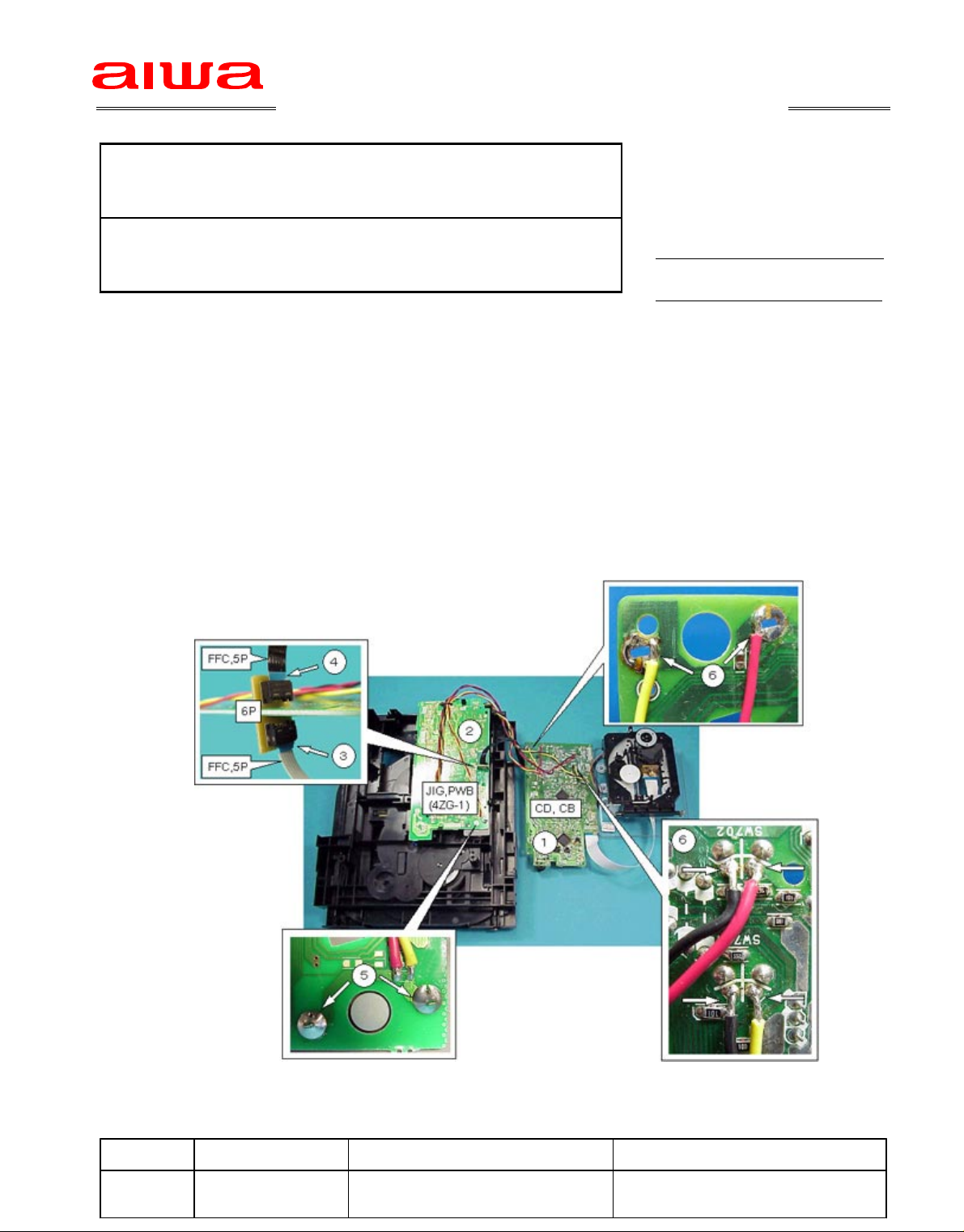
Mountingprocedure
1.RemoveCDPWBfroma4ZG1mechanism.−
2.MountthejigPWB(JIG,PWB(4ZG1))ontothe4ZG1mechanism.−−
3.ConnectFFC,5PfromTTPWBontotheconnectoronthejigPWB.(Note:Payattentionto−
connectingpositionofFFC,5P,sincea6PconnectorismountedonthejigPWB.)
4.ConnectaseparatelyobtainedFFC,5P,betweenthejigPWBandCDPWB.
5.SolderMOTORpinontojigPWB.
6.Solderextensionwires(6wires)ofthejigPWBontoSWandMOTORpinsoftheCDPWB.
1/1
Usemethod
SeparateCDPWB,etc.fromamainunitusinganextensionjigexplained in SB # 22-96-009
andthenoperatetheunitasnormal.
Ref. PartsCode Description Remarks
−−−− − −SVJ00072010 JIG,PWB(4ZG1)
−−−−− − −84ZG1673010 FCABLE,5P1.25210MMB
 Loading...