


2-4-2. DC DETECTION CIRCUIT BULLETIN NO. 91-01-02
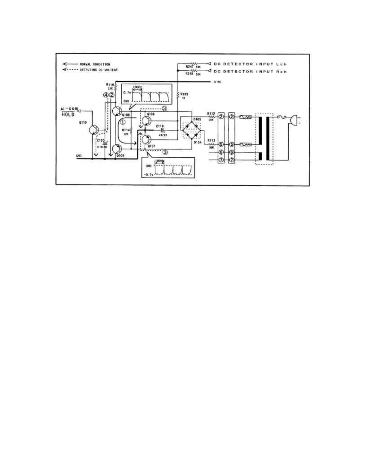
Figure 2-6 DC Detecting Circuit
This power amplifier circuit employs the output-capacitor-less (OCL) system, which connects
a speaker directly to an amplifier output, not requiring a coupling capacitor in the output stage.
The OCL circuit, which uses a positive-negative power supply, operates by balancing voltages at
zero-volts at the output point. Thus, imbalance voltage caused by faulty components, etc. results
in outputting DC voltage to the speaker output. The DC voltage may destroy a voice-coil of a
connected speaker.
The DC detection circuit shown in Figure 2-6 holds the microcomputer when a DC voltage is
detected, protecting the system.
The following describes circuit operation and flow for detecting faults:
• Under normal condition:
1) Voltage shown by the waveform (based on overseas model @ 50Hz AC) in the figure
from the bridge-diodes composed by D104 and D105 is applied to bases of transistors
Q108 and Q109. Here, transistors Q106 and Q107 are turned off because no DC voltage
is applied to their bases. (Alternate currents are cancelled by C119.)
2) Current shown by ¬ in the figure flows between bases and emitters of Q108 and Q109.
3) Q108 and Q109 are turned on, and current shown by - flows between their emitters and
collectors.
4) Q110 is turned off here. HOLD is set to “H”.
• Under abnormal status
1) Q106 and Q107 are turned on by DC voltage. (Current shown by ® in the figure flows
between collectors and emitters of Q106 and Q107.)
2) Base current on Q108 and Q109 goes off and the transistors are turned off.
3) Current shown by ¯ in the figure charges C120 and turns on Q110.
4) HOLD is set to “L” and the power to the amplifier is turned off by holding the
microcomputer.