Sony 83585X, 70664G User Manual

November 2, 2018
Sony Nimway sensor system installation manual
Introduction
The Sony Nimway sensor system is used to detect and report occupancy in rooms and at desks. The sensor system consists of four major hardware components. One door sensor, one room sensor, one desk sensor and one access point. Typically, multiple sensors talk to one access point.
The three sensor types use the same electronics inside but have different housings. The housing has a special designed masking that covers the internal PIR sensor in a specific pattern.
Whenever a sensor detects movement in its field of view it reports the movement to the access point. The access point then relays the message to the USB connected internet enabled embedded computer. The embedded computer relays the message to the Nimway cloud service for processing. The cloud service holds an occupancy state for each room. The occupancy state is either free or occupied and is calculated by fusing all sensors in a room together.
Installation
The procedure for installing the three different kinds of sensors are basically the same except where they are physically mounted.
Prerequisites
A sensor is installed in a meeting room or under a desk. The location is part of an office building which is part of a domain. The domain needs to have been configured and the maps needs to exist for the domain. The USB access points needs to be connected and configured accordingly. This is part of the greater Nimway system and not covered by this sensor installation guide.
nimway.com |
Rev: 1.00 |

November 2, 2018
Step 1 – Add the sensor to the system
Using the Android mobile installation tool which is only issued to authorized Nimway installers scan the QR code which contains the unique id for the sensor. This is needed for the system to identify the sensor. Choose the install location on the map in the mobile installation tool.
Step 2 – Open the sensor
Insert a pointy object into the small hole located on either end of the sensor and gently bend so that the internal clip detaches and the sensor opens up.
Step 3 – Connect the battery
The battery is of a special type with very long shelf time and the sensors are delivered with the battery connector disconnected. Connect the battery connector to the matching connector on the circuit board. The LED on the sensor board will light up during 750ms to indicate power on.
Step 3 – Mount the sensor
When mounting the sensors care needs to be taken of the placement. The position and direction are very important. Being a radio device, large metal surfaces should be avoided if possible as this could affect the wireless range. The surface should also be suitable for the adhesive and/or screws.
Door sensor
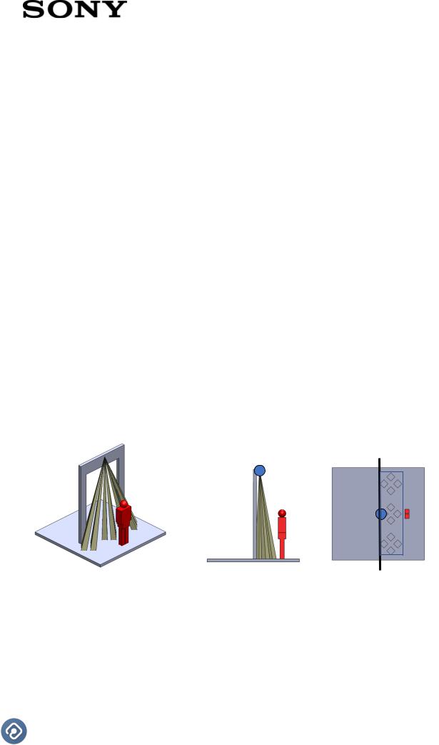
The door sensor is mounted inside the room above the entrance to the room facing down. It detects movement in the entrance area to a room. A room may have several entrances and hence multiple door sensors needs to be installed. At a 3.00-meter installation height the detection area at floor level is approximately 2.67 x 0.67 meters.
3D view |
Side view |
Bottom view |
nimway.com |
Rev: 1.00 |
 Loading...