

SONY 7607005301 SB Service Manual
HiFi Service Manual
CIRFLEXX
UMS 4201 SPCD
GLO0300
Zusätzlich erforderliche Unterlagen für den Komplettservice
Additionally required Service Documents for the Complete Service
Service
Manual
Sicherheit
Safety
Materialnr./Part No.
720108000000
Materialnummer/Part Number 720107727500
Änderungen vorbehalten/Subject to alteration • Printed in Germany
H-S43 • 0403 • 8002/8012 oUKIRL, 8003/8013 oD, 8005/8015
http://www.grundig.com
Grundig Service
Hotline Deutschland…
Technik:
TV
TV
SAT
VCR/LiveCam
HiFi/Audio
Car Audio
Telekommunikation
Planatron
Ersatzteil-Verkauf: Mo.-Fr. 8.00-19.00 Uhr
Kundendienst/Werkstätten:
*0,12€/Min. über Arcor
(8.00-22.00 Uhr)
…Mo.-Fr. 8.00-18.00 Uhr
0180/52318-41*
0180/52318-49*
0180/52318-48*
0180/52318-42*
0180/52318-43*
0180/52318-44*
0180/52318-45*
Fax:
Telefon: 0180/52318-40*
Telefon:
Fax:
0180/52318-51*
0180/52318-99*
0180/52318-50*Fax:
Mo.-Fr. 8.00-18.00 Uhr
0180/52318-52*
0180/52318-46*

GRUNDIG Service CIRFLEXX UMS 4201 SPCD
Es gelten die Vorschriften und Sicherheitshinweise gemäß dem Service Manual "Sicherheit",
Materialnummer 720108000000, sowie zusätzlich die eventuell abweichenden, landesspezifischen Vorschriften!
Inhaltsverzeichnis
Seite
Allgemeiner Teil ........................... 1 - 2 … 1 - 11
Messgeräte / Messmittel ............................................................ 1 - 2
Technische Daten ...................................................................... 1 - 3
Servicehinweise ......................................................................... 1 - 3
Ausbauhinweise ......................................................................... 1 - 4
Bedienhinweise .......................................................................... 1 - 8
Abgleichvorschriften .................................. 2 - 1
Platinenabbildungen
und Schaltpläne ........................... 3 - 1 … 3 - 20
Blockschaltplan .......................................................................... 3 - 1
Verdrahtungsplan ....................................................................... 3 - 2
Schaltpläne:
Verstärkerteil .......................................................................... 3 - 5
Rundfunkteil ........................................................................... 3 - 9
CD- und Prozessorteil .......................................................... 3 - 11
MP3-Teil ............................................................................... 3 - 15
Netzteil ................................................................................. 3 - 17
Bedien-Platten ...................................................................... 3 - 18
Display-Platte ....................................................................... 3 - 19
Platinenabbildungen:
Verstärkerteil .......................................................................... 3 - 7
Rundfunkteil ........................................................................... 3 - 8
CD- und Prozessorteil .......................................................... 3 - 13
MP3-Teil ............................................................................... 3 - 16
Netzteil ................................................................................. 3 - 17
Bedien-Platten ...................................................................... 3 - 18
Display-Platte ....................................................................... 3 - 20
The regulations and safety instructions shall be
valid as provided by the "Safety" Service Manual,
part number 720108000000, as well as the respective national deviations!
Table of Contents
Page
General Section ............................ 1 - 2 … 1 - 15
Measuring Instruments / Equipment .......................................... 1 - 2
Technical Data ........................................................................... 1 - 3
Service Hints .............................................................................. 1 - 3
Disassembly Instructions ........................................................... 1 - 4
Operating Hints ........................................................................ 1 - 12
Adjustment Procedures.............................. 2 - 2
Layout of PCBs
and Circuit Diagrams ................... 3 - 1 … 3 - 20
Block Diagram ............................................................................ 3 - 1
Wiring Diagram .......................................................................... 3 - 2
Circuit Diagrams:
Amplifier Part .......................................................................... 3 - 5
Tuner Part .............................................................................. 3 - 9
CD and Processor Part ........................................................ 3 - 11
MP3 Part .............................................................................. 3 - 15
Mains Unit ............................................................................ 3 - 17
Keyboards ............................................................................ 3 - 18
Display PCB ......................................................................... 3 - 19
Layout of the PCBs:
Amplifier Part .......................................................................... 3 - 7
Tuner Part .............................................................................. 3 - 8
CD and Processor Part ........................................................ 3 - 13
MP3 Part .............................................................................. 3 - 16
Mains Unit ............................................................................ 3 - 17
Keyboards ............................................................................ 3 - 18
Display PCB ......................................................................... 3 - 20
Explosionszeichnung und
Ersatzteilliste .................................. 4 - 1 … 4 - 3
Explosionszeichnung ................................................................. 4 - 1
Ersatzteilliste .............................................................................. 4 - 2
Allgemeiner Teil
Messgeräte / Messmittel
Mess-Sender Wobbelsender
Oszilloskop Digitalvoltmeter
Klirrfaktormessgerät
Exploded View and
Spare Parts List .............................. 4 - 1 … 4 - 3
Exploded View ........................................................................... 4 - 1
Spare Parts List ......................................................................... 4 - 2
General Section
Measuring Instruments / Equipment
Signal generator Sweep generator
Oscilloscope Digital voltmeter
Distortion meter
1 - 2

GRUNDIG Service CIRFLEXX UMS 4201 SPCD
Technische Daten
Verstärkerteil
Ausgangsleistung:
Sinusleistung ........................................................................ 2 x 12W
Musikleistung ....................................................................... 2 x 20W
Eingangsempfindlichkeit/Impedanz ............................. 500mV/22kΩ
Empfangsteil
Empfangsbereich FM ............................................. 87,5 ...108,0MHz
Empfangsbereich MW .............................................. 522 ... 1620kHz
CD Teil
Frequenzgang ............................................................ 20Hz ... 20kHz
Geräuschspannungsabstand (wtd.) ........................................ >90dB
MP3 Features
Multi-session-fähig
Wiedergabe-Format ..................................... MPEG 1 Layer 3 (MP3)
Sampling Frequenz ............................................................. 44,1 kHz
File System/File Management ........... ISO 9660; Level 1 kompatibel
Max. Alben .................................................................................... 99
Max. Files ................................................ 400 pro CD/255 pro Album
Bitrate ............................................................... variabel, 8-320 kbit/s
Spannungsversorgung
Betriebsspannung ................................................................... 230V~
Netzfrequenz ........................................................................ 50/60Hz
max. Leistungsaufnahme ........................................................... 75W
Leistungsaufnahme in Standby ............................................... <1,5W
Technical Data
Amplifier unit
Output:
Sinusoidal power .................................................................. 2 x 12W
Music signal power .............................................................. 2 x 20W
Input sensitivity/impedance .......................................... 500mV/22kΩ
Receiver unit
Reception range FM ............................................. 87.5 ... 108.0MHz
Reception range MW ............................................... 522 ... 1620kHz
CD unit
Frequency response .................................................. 20Hz ... 20kHz
Noise voltage ratio (wtd.) ........................................................ >90dB
MP3 features
Multi-session capable
Playback format ............................................ MPEG 1 layer 3 (MP3)
Sampling frequency ............................................................ 44.1 kHz
File system/file management .............. ISO 9660; level 1 compatible
Max. albums .................................................................................. 99
Max. files ............................................... 400 per CD / 255 per album
Bit rate .............................................................. Variable, 8-320 kbit/s
Power supply
Operating voltage.................................................................... 230V~
Mains frequency ................................................................... 50/60Hz
Max. power consumption ........................................................... 75W
Power consumption in stand-by mode .................................... <1.5W
Abmessungen und Gewicht
Abmessungen Gerät .......................... B x H x T 175 x 245 x 230mm
Gewicht Gerät ........................................................................... 3,1kg
Abmessungen Lautsprecher .............. B x H x T 130 x 240 x 160mm
Gewicht pro Lautsprecher .........................................................1,3kg
Servicehinweise
Achtung: ESD-Vorschriften beachten
Vor Öffnen des Gehäuses Netzstecker ziehen.
Leitungsverlegung
Bevor Sie die Leitungen und insbesondere die Masseleitungen lösen,
muss die Leitungsverlegung zu den einzelnen Baugruppen beachtet
werden.
Nach erfolgter Reparatur ist es notwendig, die Leitungsführung wieder
in den werkseitigen Zustand zu versetzen um evtl. spätere Ausfälle
oder Störungen zu vermeiden.
CD-Teil
Bei Ausbau der CD-Lasereinheit muss vor
Abziehen der Steckverbindungen eine
Schutzlötstelle auf der Leiterplatte der
Lasereinheit angebracht werden, um eine
Zerstörung der Laserdiode durch statische
Aufladung zu vermeiden.
Beim Einbau einer neuen Lasereinheit
(CD-Laufwerk) muss nach Einstecken
der Steckverbinder die werkseitig angebrachte Schutzlötstelle entfernt werden!
Dimensions and weight
Device dimensions ............................W x H x D 175 x 245 x 230mm
Device weight ............................................................................ 3.1kg
Loadspeaker dimensions .................. W x H x D 130 x 240 x 160mm
Weight per loudspeaker ............................................................1.3kg
Service Hints
Attention: Observe the ESD safety regulations
Disconnect the mains plug before opening the set.
Wiring
Before disconnecting any leads and especially the earth connecting
leads observe the way they are routed to the individual assemblies.
On completion of the repairs the leads must be laid out as originally
fitted at the factory to avoid later failures or disturbances.
CD Section
When removing the Laser pick-up, the Laser
pick-up PCB must be provided with a protective soldered joint before unplugging the
connectors to avoid damage to the Laser
diode by static charges.
When inserting the new Laser pick-up (CD
drive mechanism) the soldered joint fitted
at the factory must be removed after the
connectors are plugged in.
1 - 3
Schutzlötstelle
protective soldered joint
GRUNDIG Service CIRFLEXX UMS 4201 SPCD
Ausbauhinweise
Bevor Sie Leitungen lösen, muss die Leitungsverlegung beachtet
werden. Nach erfolgter Reparatur ist es notwendig, die Leitungsführung in den werkseitigen Zustand zu versetzen.
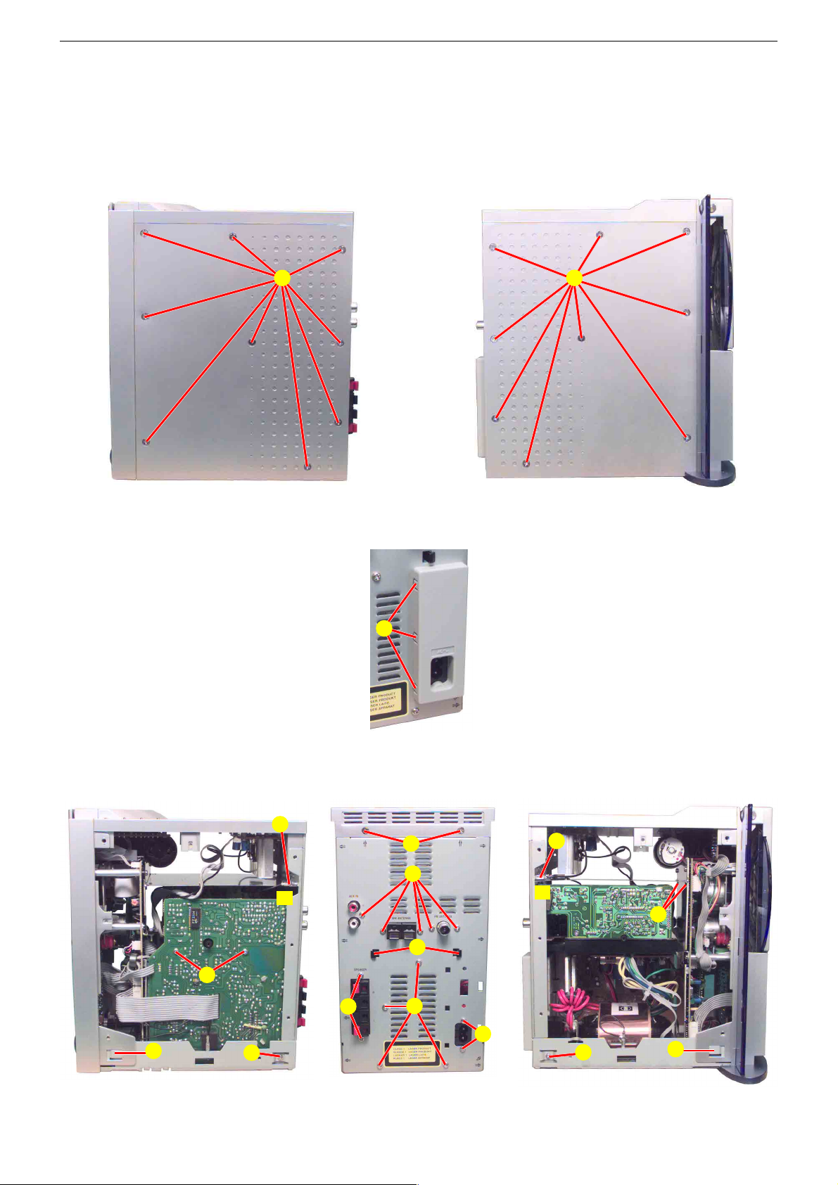
1. Gehäuseseitenteile
- 18 Schrauben A (Fig. 1, 2) herausdrehen.
- Gehäuseseitenteile nach hinten schieben und abnehmen.
Disassembly Instructions
Before disconnecting any leads observe the way they are routed.
On completion of the repairs the leads must be laid out as
originally fitted at the factory.
1. Cabinet Sides
- Undo 18 screws B (Fig. 1, 2).
- Move the sides to the rear and remove.
AA
Fig. 1
2. Gehäuserückwand
- Gehäuseseitenteile abnehmen (Punkt 1).
- Netzbuchsenabdeckung ausrasten und abnehmen B (Fig. 3).
- 7 Schrauben C (Fig. 5) herausdrehen.
- 2 Schrauben D (Fig. 5) herausdrehen.
- 6 Schrauben E (Fig. 4, 5, 6) herausdrehen.
- 2 Schrauben F (Fig. 5) herausdrehen.
- Gehäuseoberteil mit Spannungsregler-Platte
hinten anheben, 2 Rastnasen H (Fig. 5) ausrasten, 2 Masseverbindungen G (Fig. 4, 6) abziehen
und Gehäuserückwand abnehmen.
3. Gehäuseoberteil mit Spannungsregler-Platte
- Gehäuserückwand abnehmen (Punkt 2).
- Gehäuseoberteil mit Spannungsregler-Platte
hinten anheben, an der Frontblende aushängen
und abnehmen.
- Bei Bedarf Steckverbindungen lösen.
G
f
B
Fig. 3
D
C
Fig. 2
2. Cabinet Rear
- Remove the Sides (point 1).
- Disengage the cover of the mains socket B
(Fig. 3).
- Undo 7 screws C (Fig. 5).
- Undo 2 screws D (Fig. 5).
- Undo 6 screws E (Fig. 4, 5, 6).
- Undo 2 screws F (Fig. 5).
- Lift the Cabinet top together with the Regulation
PCB at the rear, disengage hooks H (Fig. 5),
unplug 2 ground connections G (Fig. 4, 6) and
remove the cabinet rear.
3. Cabinet Top together with the Regulation PCB
- Remove the cabinet rear (point 2).
- Lift the Cabinet top together with the regulation
PCB at the rear, disengage at the front and
remove.
- When necessary unplug the connections.
G
f
L
H
S
C
E
F
T
Fig. 4 Fig. 5 Fig. 6
E
1 - 4
E
T
GRUNDIG Service CIRFLEXX UMS 4201 SPCD
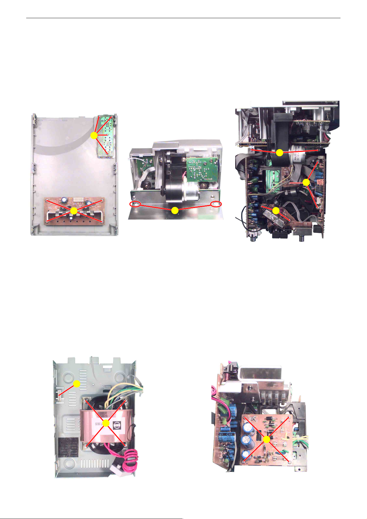
4. Spannungsregler-Platte
- Gehäuseoberteil mit Spannungsregler-Platte abnehmen (Punkt 3).
- 4 Schrauben I (Fig. 7) herausdrehen.
5. Bedienplatte Gehäuseoberteil
- Gehäuseoberteil mit Spannungsregler-Platte abnehmen (Punkt 3).
- 4 Schrauben J (Fig. 7) herausdrehen.
6. Abschirmblech des FM-Tuner
- Gehäuseoberteil mit Spannungsregler-Platte abnehmen (Punkt 3).
- Abschirmblech ablöten K (Fig. 8) und abnehmen. Abschirmblech
beim Einbau wieder in das Abschirmblech der CD-Leiterplatte
einhängen L (Fig. 6).
J
4. Regulation PCB
- Remove the cabinet top together with the regulation PCB (point 3).
- Undo 4 screws I (Fig. 7).
5. Operating PCB of Cabinet Top
- Remove the cabinet top together with the regulation PCB (point 3).
- Undo 4 screws J (Fig. 7).
6. Shielding Plate of FM Tuner
- Remove the cabinet top together with the regulation PCB (point 3).
- Unsolder and remove the shielding plate K (Fig. 8). When
reassembling take care to put it in the shieling plate of the CD PCB
L (Fig. 6).
O
N
I
Fig. 7
7. Leiterplatte FM-Tuner/Antennen-Buchsen
- Abschirmblech des FM-Tuners abnehmen (Punkt 6).
- 2 Schrauben M (Fig. 9) herausdrehen.
- Bei Bedarf Steckverbindungen lösen.
8. Leiterplatten AM/ZF und PLL
- Abschirmblech des FM-Tuners abnehmen (Punkt 6).
- 3 Schrauben N (Fig. 9) herausdrehen.
- Bei Bedarf Steckverbindungen lösen.
9. Montagerahmen mit Leiterplatten
- Abschirmblech des FM-Tuners abnehmen (Punkt 6).
- 2 Schrauben O (Fig. 9) herausdrehen.
- Bei Bedarf Steckverbindungen lösen.
- Beim Einbau darauf achten, dass die Verstärkerplatte in die Führung P (Fig. 10) eingreift.
Fig. 8
P
K
M
Fig. 9
7. FM Tuner/Antenna Sockets PCB
- Remove the shielding plate of the FM tuner (point 6).
- Undo 2 screws M (Fig. 9).
- When necessary unplug the connections.
8. AM/IF and PLL PCBs
- Remove the shielding plate of the FM tuner (point 6).
- Undo 3 screws N (Fig. 9).
- When necessary unplug the connections.
9. Mounting Frame with PCBs
- Remove the shielding plate of the FM tuner (point 6).
- Undo 2 screws O (Fig. 9).
- When necessary unplug the connections.
- When reassembling take care, that the Amplifier PCB engages with
its guide P (Fig. 10).
Fig. 10
Q
R
Fig. 11
1 - 5
GRUNDIG Service CIRFLEXX UMS 4201 SPCD
10. Transformator
- Montagerahmen lösen (Punkt 9).
- 4 Schrauben Q (Fig. 10) herausdrehen.
- Bei Bedarf Steckverbindungen lösen.
11. Leiterplatte Netzteil
- Montagerahmen lösen (Punkt 9).
- 4 Schrauben R (Fig. 11) herausdrehen.
- Bei Bedarf Leitungen zur Netzteilplatte ablöten.
12. Verstärkerplatte
- Montagerahmen lösen (Punkt 9).
- 2 Schrauben S (Fig. 4) herausdrehen.
- Bei Bedarf Steckverbindungen lösen.
13. Front mit CD-Teil
- Montagerahmen lösen (Punkt 9).
- 2 Rastungen T (Fig. 4, 6) lösen.
- Bei Bedarf Steckverbindungen lösen.
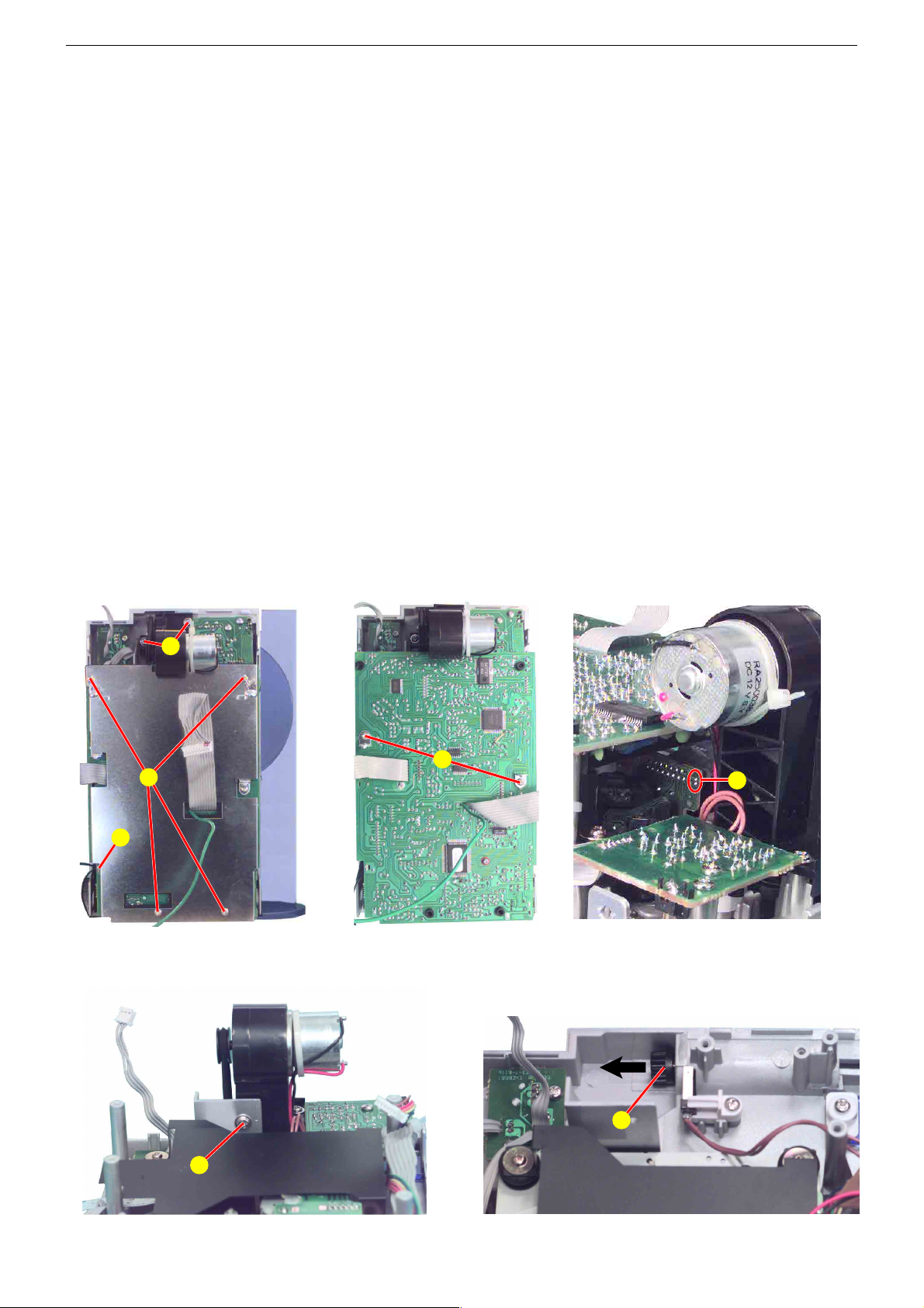
14. CD-Leiterplatte
- Front mit CD-Teil abnehmen (Punkt 13).
- 4 Schrauben U (Fig. 12) herausdrehen.
- Masselötstelle V (Fig. 12) auflöten.
- 2 Schrauben W (Fig. 13) herausdrehen.
- Vor abziehen des Flexprints zum CD-Laufwerk Sicherheitslötstelle
X (Fig. 14) schließen.
- Bei Bedarf Steckverbindungen lösen.
15. Antrieb CD-Tür
- CD-Leiterplatte ausbauen (Punkt 14).
- 3 Schrauben Y (Fig. 12, 15) herausdrehen.
- Antrieb aushängen und abnehmen.
- CD-Tür-Achse Z (Fig. 16) in Pfeilrichtung abziehen.
10. Transformer
- Loosen the mounting frame (point 9).
- Undo 4 screws Q (Fig. 10).
- When necessary unplug the connections.
11. Mains Unit PCB
- Loosen the mounting frame (point 9).
- Undo 4 screws R (Fig. 11).
- When necessary unsolder the wires to the mains unit.
12. Amplifier PCB
- Loosen the mounting frame (point 9).
- Undo 2 screws S (Fig. 4).
- When necessary unplug the connections.
13. Front together with the CD Part
- Loosen the mounting frame (point 9).
- Disengage 2 hooks T (Fig. 4, 6).
- When necessary unplug the connections.
14. CD PCB
- Remove the front together with the CD part (point 13).
- Undo 4 screws U (Fig. 12).
- Unsolder ground solder connection V (Fig. 12).
- Undo 2 screws W (Fig. 13).
- Short circuit the protective soldered joint X (Fig. 14) before
disconnecting the flexprint to the CD mechanism.
- When necessary unplug the connections.
15. CD Door Drive
- Remove the CD PCB (point 14).
- Undo 3 screws Y (Fig. 12, 15).
- Unhook the drive and remove.
- Pull out the CD door axle Z (Fig. 16) in direction of the arrow.
V
U
Y
W
X
Fig. 13 Fig. 14Fig. 12
Y
Z
Fig. 16Fig. 15
1 - 6
GRUNDIG Service CIRFLEXX UMS 4201 SPCD
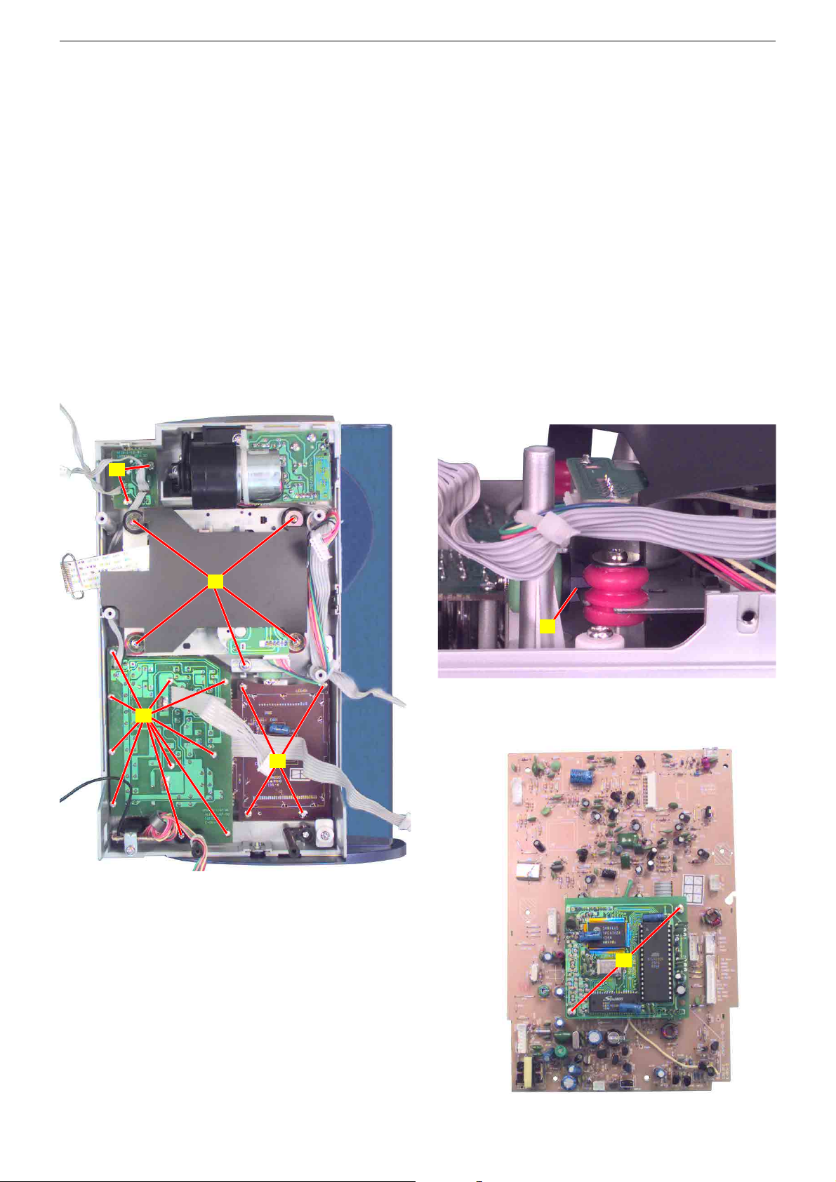
16. CD-Laufwerk
- CD-Leiterplatte ausbauen (Punkt 14).
- 5 Schrauben A (Fig. 17) herausdrehen.
- Bei Bedarf Steckverbindungen lösen.
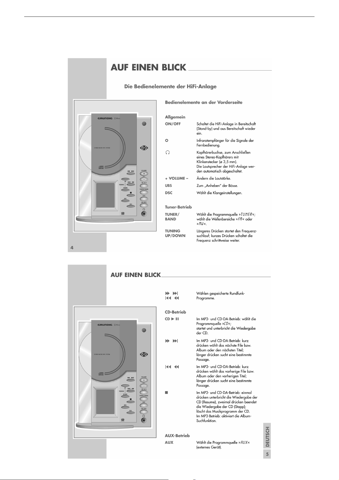
- Beim Einbau die Farbe der Gummidämpfer beachten!
Das Laufwerkchassis muss in die Führung B (Fig. 18) des grünen
Gummidämpfers eingreifen.
17. Bedienplatte Frontseite
- CD-Leiterplatte ausbauen (Punkt 14).
- 10 Schrauben C (Fig. 17) herausdrehen.
18. Displayplatte
- CD-Leiterplatte ausbauen (Punkt 14).
- 4 Schrauben D (Fig. 17) herausdrehen.
19. IR-Empfänger-Leiterplatte
- Gehäuseoberteil abnehmen (Punkt 3).
- 2 Schrauben E (Fig. 17) herausdrehen.
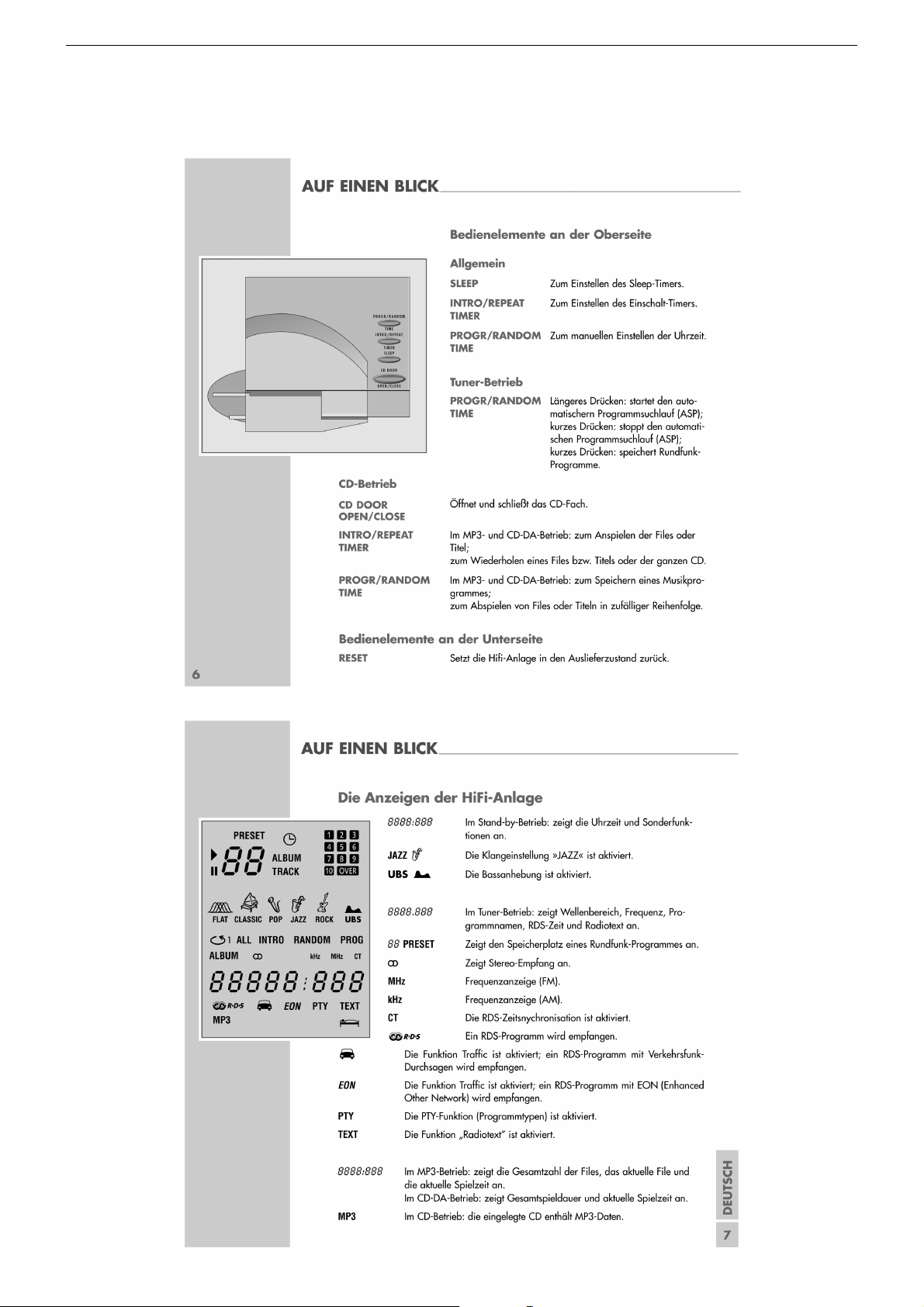
20. MP3-Platte
- CD-Leiterplatte ausbauen (Punkt 14).
- 2 Schrauben F (Fig. 19) herausdrehen.
- MP3-Platte abziehen.
E
16. CD Mechanism
- Remove the CD PCB (point 14).
- Undo 5 screws A (Fig. 17).
- When necessary unplug the connections.
- When reassembling pay attention to the different colors of the
dampers! The mechanism chassis must engage with the guide B
(Fig. 18) of the green damper.
17. Operating PCB Front
- Remove the CD PCB (point 14).
- Undo 10 screws C (Fig. 17).
18. Displayplatte
- Remove the CD PCB (point 14).
- Undo 4 screws D (Fig. 17).
19. IR Receiver PCB
- Remove the cabinet top (point 3).
- Undo 2 screws E (Fig. 17).
20. MP3 PCB
- Remove the CD PCB (point 14).
- Undo 2 screws F (Fig. 19).
- Pull up the MP3 PCB.
Fig. 17
A
B
Fig. 18
C
D
F
1 - 7
Fig. 19
GRUNDIG Service CIRFLEXX UMS 4201 SPCD
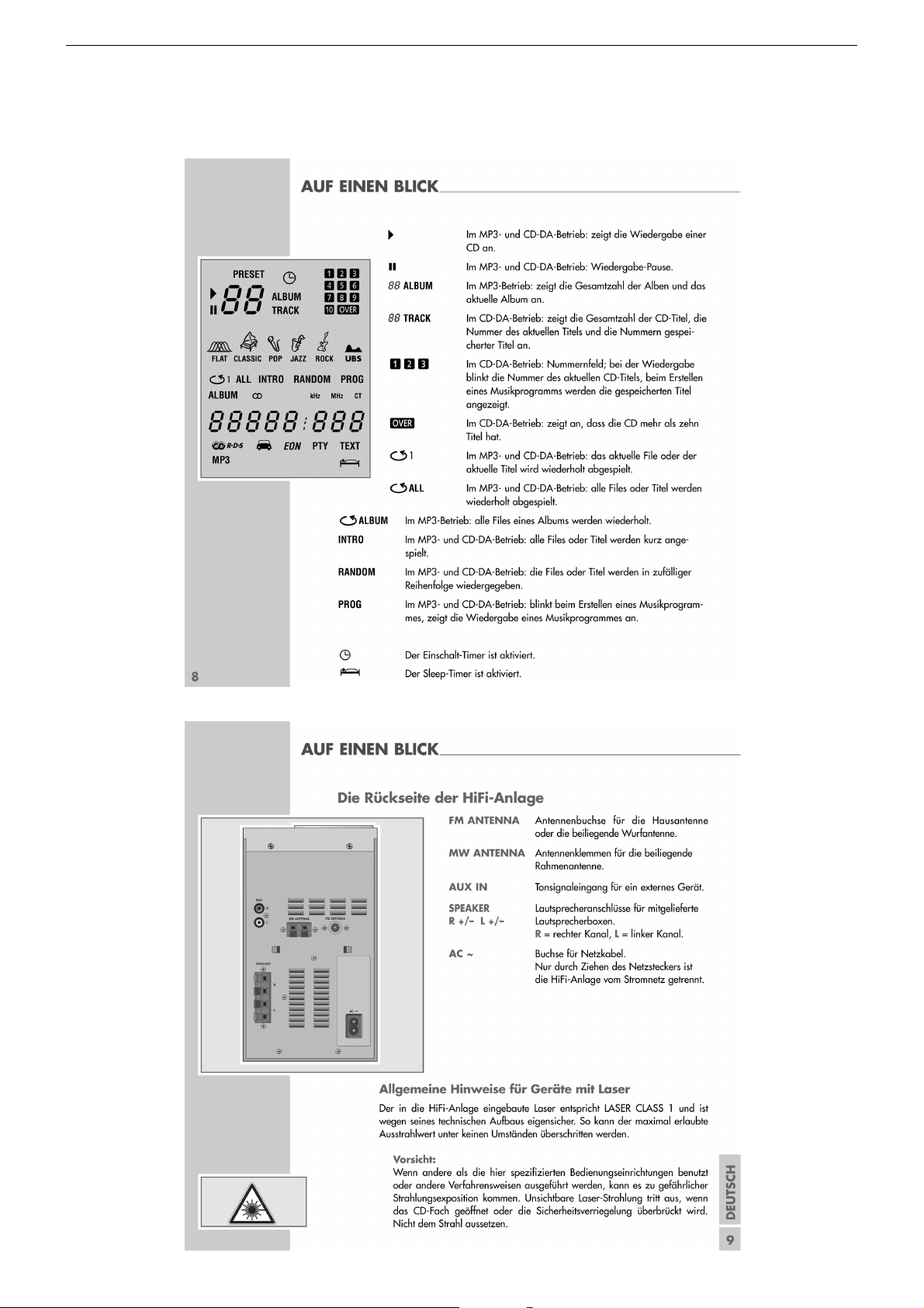
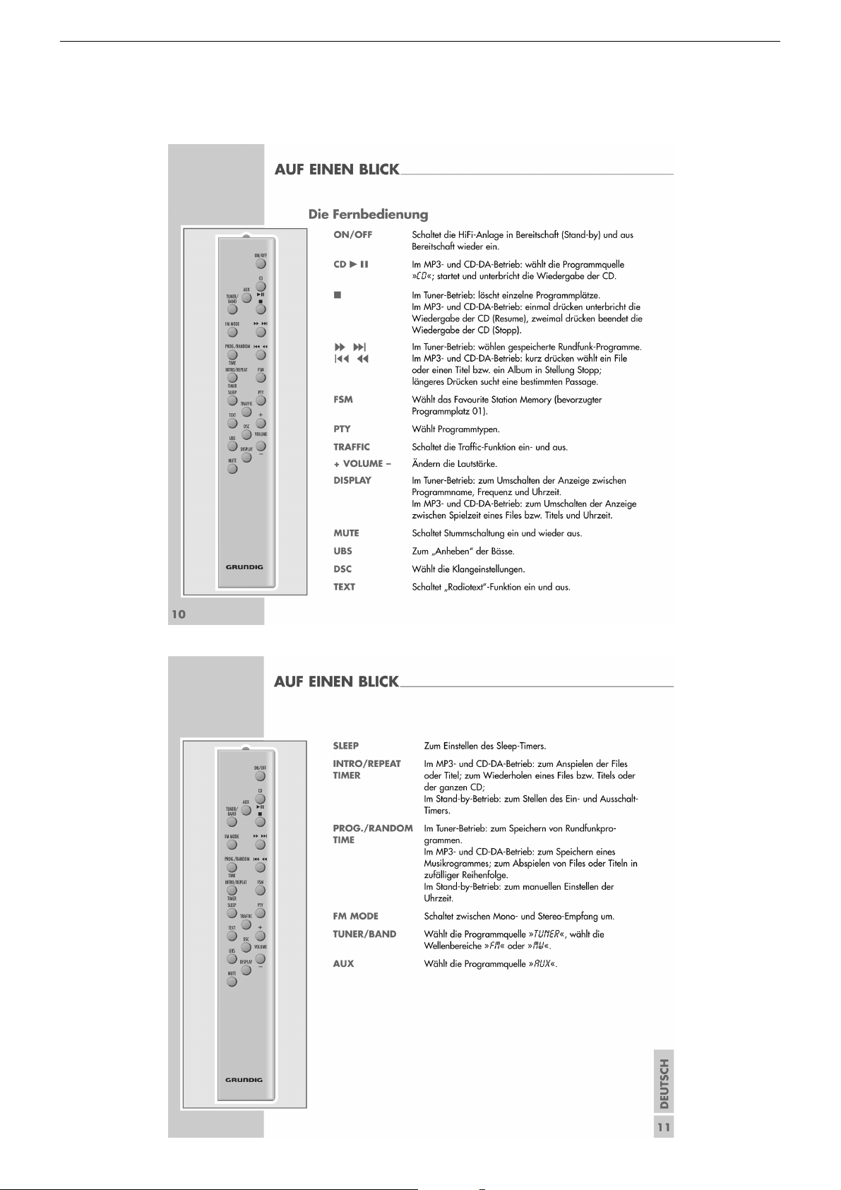
Bedienhinweise
Dieses Kapitel enthält Auszüge aus der Bedienungsanleitung. Weitergehende Informationen entnehmen Sie bitte der gerätespezifischen
Bedienungsanleitung, deren Materialnummer Sie in der entsprechenden Ersatzteilliste finden.
1 - 8
GRUNDIG Service CIRFLEXX UMS 4201 SPCD
1 - 9
GRUNDIG Service CIRFLEXX UMS 4201 SPCD
1 - 10
GRUNDIG Service CIRFLEXX UMS 4201 SPCD
1 - 11
GRUNDIG Service CIRFLEXX UMS 4201 SPCD
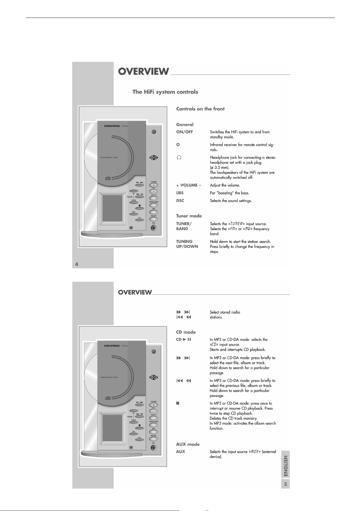
Operating Hints
This chapter contains excerpts from the operating instructions. For further particulars please refer to the appropriate user instructions the part number
of which is indicated in the relevant spare parts list.
1 - 12
 Loading...