

17" LCD Color Monitor AOC 712Si
Service
Service
Service
Horizontal Frequency
30- 80 kHz
Table Of Contents
Description Page Description Page
Table Of Contents.......…….................……...........…........1
Important Safety Notice.………….…..................……......2
Revision List.…........................………................……......3
1.Product Feature..............................………........4
2.LCD Monitor Description…………………………….......6
3.Operation Instruction…………...............……...........7
3.1.General Instructions...........................…...........7
3.2.Control Buttons…………….…..............……...............7
3.3 Adjusting the Picture...........................…............8
4.Input/Output Specification............……………...........10
4.1.Analog Connector............…………........……….......10
4.2.Factory Preset Display Modes...............…..........10
5.Panel Specification.....………………..................11
5.1. General Feature…….....………………..................11
5.2. Optical Characteristics………………………………11
5.3. Electrical Characteristics……………………………12
6.Block Diagram…….…................…………................13
6.1.Monitor Exploded View……………………............13
6.2.Software Flow Chart…………………....….......14
6.3.Electrical Block Diagram…………..…..….......16
7.Schematic……………...............................….....17
7.1 Main Board.............................................17
7.2 Power Board....……...........……........................27
8.PCB Layout..…………...........……...........................29
8.1.Main Board………..................……....................29
8.2.Power Board…....................……………..................30
8.3.Key Board………........…................………............32
9.Maintainability………............................……….........33
9.1.Equipments and Tools Requirement......……….......33
9.2.Trouble Shooting…………..............................34
10.White-Balance, Luminance adjustment....................42
11.BOM List….................……......................….............43
12.Different Parts List………………………...…………..58
SAFETY NOTICE
ANY PERSON ATTEMPTING TO SERVICE THIS CHASSIS MUST FAMILIARIZE HIMSELF WITH THE
CHASSIS AND BE AWARE OF THE NECESSARY SAFETY PRECAUTIONS TO BE USED WHEN SERVICING
ELECTRONIC EQUIPMENT CONTAINING HIGH VOLTAGES.
CAUTION: USE A SEPARATE ISOLATION TRANSFOMER FOR THIS UNIT WHEN SERVICING
1

17" LCD Color Monitor AOC 712Si
Important Safety Notice
Proper service and repair is important to the safe, reliable operation of all AOC Company Equipment. The service
procedures recommended by AOC and described in this service manual are effective methods of performing service
operations. Some of these service operations require the use of tools specially designed for the purpose. The
special tools should be used when and as recommended.
It is important to note that this manual contains various CAUTIONS and NOTICES which should be carefully read in
order to minimize the risk of personal injury to service personnel. The possibility exists that improper service
methods may damage the equipment. It is also important to understand that these CAUTIONS and NOTICES ARE
NOT EXHAUSTIVE. AOC could not possibly know, evaluate and advise the service trade of all conceivable ways in
which service might be done or of the possible hazardous consequences of each way. Consequently, AOC has not
undertaken any such broad evaluation. Accordingly, a servicer who uses a service procedure or tool which is not
recommended by AOC must first satisfy himself thoroughly that neither his safety nor the safe operation of the
equipment will be jeopardized by the service method selected.
Hereafter throughout this manual, AOC Company will be referred to as AOC.
WARNING
Use of substitute replacement parts, which do not have the same, specified safety characteristics might create
shock, fire, or other hazards.
Under no circumstances should the original design be modified or altered without written permission from AOC.
AOC assumes no liability, express or implied, arising out of any unauthorized modification of design.
Servicer assumes all liability.
FOR PRODUCTS CONTAINING LASER:
DANGER-Invisible laser radiation when open AVOID DIRECT EXPOSURE TO BEAM.
CAUTION-Use of controls or adjustments or performance of procedures other than those specified herein may
result in hazardous radiation exposure.
CAUTION -The use of optical instruments with this product will increase eye hazard.
TO ENSURE THE CONTINUED RELIABILITY OF THIS PRODUCT, USE ONLY ORIGINAL MANUFACTURER'S
REPLACEMENT PARTS, WHICH ARE LISTED WITH THEIR PART NUMBERS IN THE PARTS LIST SECTION OF
THIS SERVICE MANUAL.
Take care during handling the LCD module with backlight unit
-Must mount the module using mounting holes arranged in four corners.
-Do not press on the panel, edge of the frame strongly or electric shock as this will result in damage to the screen.
-Do not scratch or press on the panel with any sharp objects, such as pencil or pen as this may result in damage to
the panel.
-Protect the module from the ESD as it may damage the electronic circuit (C-MOS).
-Make certain that treatment person’s body is grounded through wristband.
-Do not leave the module in high temperature and in areas of high humidity for a long time.
-Avoid contact with water as it may a short circuit within the module.
-If the surface of panel becomes dirty, please wipe it off with a soft material. (Cleaning with a dirty or rough cloth may
damage the panel.)
2
17" LCD Color Monitor AOC 712Si
Revision List
Revision Date Revision History TPV Model
A00 Apr.-21-2007 First Version Release
T77CNNNKHAA1FIE
T77CNNMDHAA4NIE
3
17" LCD Color Monitor AOC 712Si
1. Product Feature
Driving system TFT Color LCD
LCD Panel Size 43.2cm(17.0")
Pixel pitch 0.264mm( H ) × 0.264mm( V )
Video R,G,B Analog Interface
Input Separate Sync. H/V TTL
H-Frequency 30kHz – 80kHz
V-Frequency 55-75Hz
Display Colors 16.2M Colors
Dot Clock 135MHz
Max. Resolution 1280 × 1024 @75Hz
Plug & Play VESA DDC2BTM
EPA ENERGY STAR® ON Mode ≤37W
OFF Mode ≤1W
Input Connector 15-pin D-Sub
External
Input Video Signal Analog:0.7Vp-p(standard),
75 OHM, Positive
Maximum Screen Size Horizontal : 338mm
Vertical : 270mm
Power Source 100~240VAC,47~63Hz
Environmental Operating Temp: 5° to 35°C
Considerations Storage Temp.: -20° to 60°C
Operating Humidity: 10% to 85%
Dimension 399(H)×433(W)×133(D)mm
Weight (N. W.) 4.25kg Unit (net)
Switch Auto Adjust Key
Brightness
Contrast
Power Button
MENU
Functions Contrast
Controls:
Brightness
Focus
Clock
H. Position
V. Position
Auto Config
Language
Information
OSD Setup
4

17" LCD Color Monitor AOC 712Si
(Warm)Color
(Cool)Color
User Color temperature
sRGB
Reset
Exit
Regulatory Compliance CE, FCC, cULus, TUV-S
5
17" LCD Color Monitor AOC 712Si
(
)
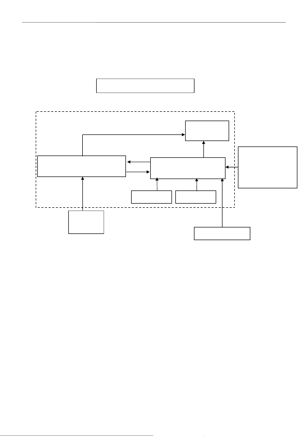
2. LCD Monitor Description
The LCD MONITOR will contain a main board, a power board, a key board and an audio board which house the flat
panel control logic, brightness control logic and DDC.
The power board will provide AC to DC voltage to drive the backlight of panel and the main board chips each
voltage.
Power Board
Include Adapter and Inverter
Monitor Block Diagram
CCFL Drive.
Flat Panel and
CCFL backlight
Main Board
RS232 Connector
For white balance
adjustment in factory
mode
Audio Board
Key Board
OK
HOST Computer
Video signal, DDC
6
17" LCD Color Monitor AOC 712Si
3. Operating Instructions
3.1 General Instructions
Press the power button to turn the monitor on or off. The other control buttons are located at the front panel of
the monitor. By changing these settings, the picture can be adjusted to your personal preferences.
The power cord should be connected.
-
Connect the video cable from the monitor to the video card.
-
Press the power button to turn on the monitor, the power indicator will light up.
-
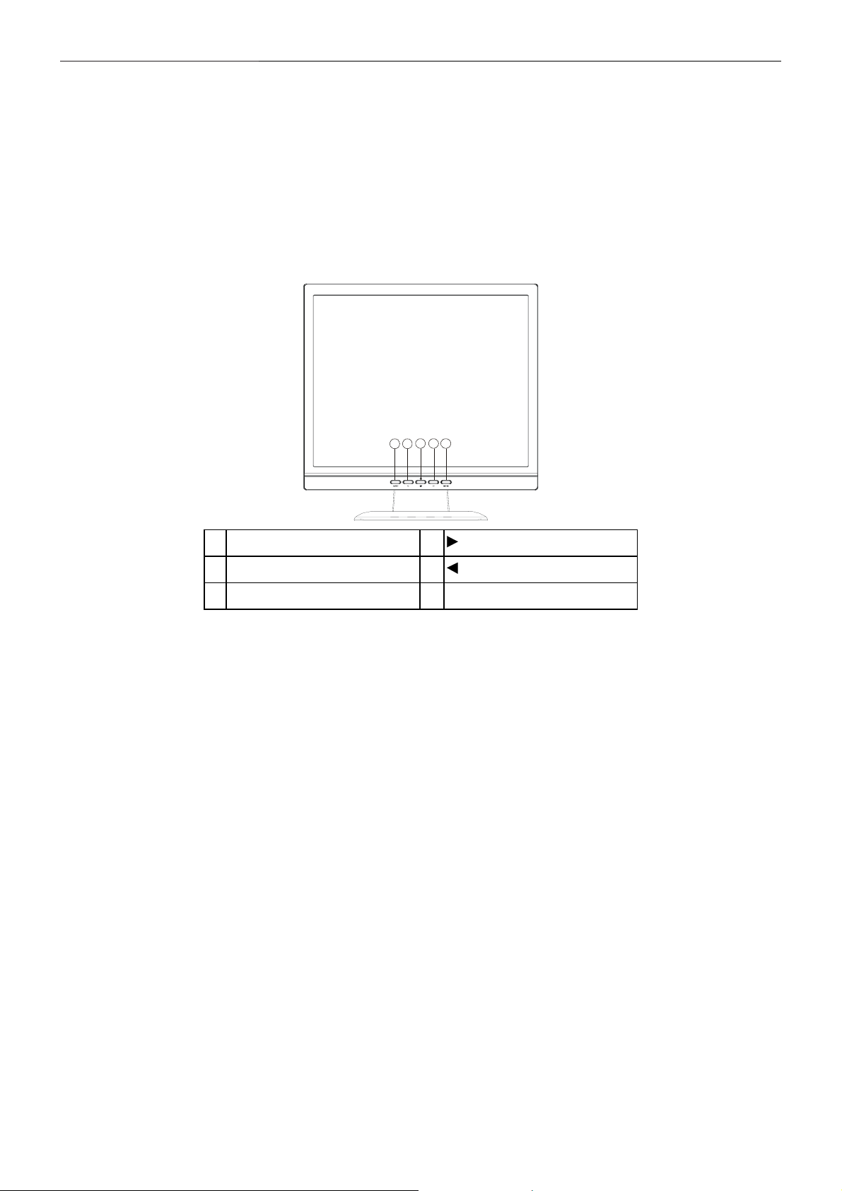
3.2 Control Buttons
3 4 5
1 2
1. Auto Adjust button / Exit 2. / Brightness
3. Power Button/ LED 4. / Contrast
5. MENU / ENTER
• Power Button:
Press this button to turn the monitor ON or OFF.
• Power Indicator:
Blue — Power On mode.
Orange — Off mode.
• MENU / ENTER :
Activate OSD menu when OSD is OFF or activate/de-activate adjustment function when OSD is ON or Exit OSD
menu when in Brightness /Contrast Adjust OSD status.
• Brightness :
Adjust brightness or function adjust.
• Contrast :
Adjust contrast or function adjust.
• Auto Adjust button / Exit:
1. When OSD menu is in active status, this button will act as EXIT-KEY (EXIT OSD menu).
2. When OSD menu is in off status, press this button for 2 seconds to activate the Auto Adjustment function.
The Auto Adjustment function is used to set the HPos, VPos, Clock and Focus.
7
17" LCD Color Monitor AOC 712Si
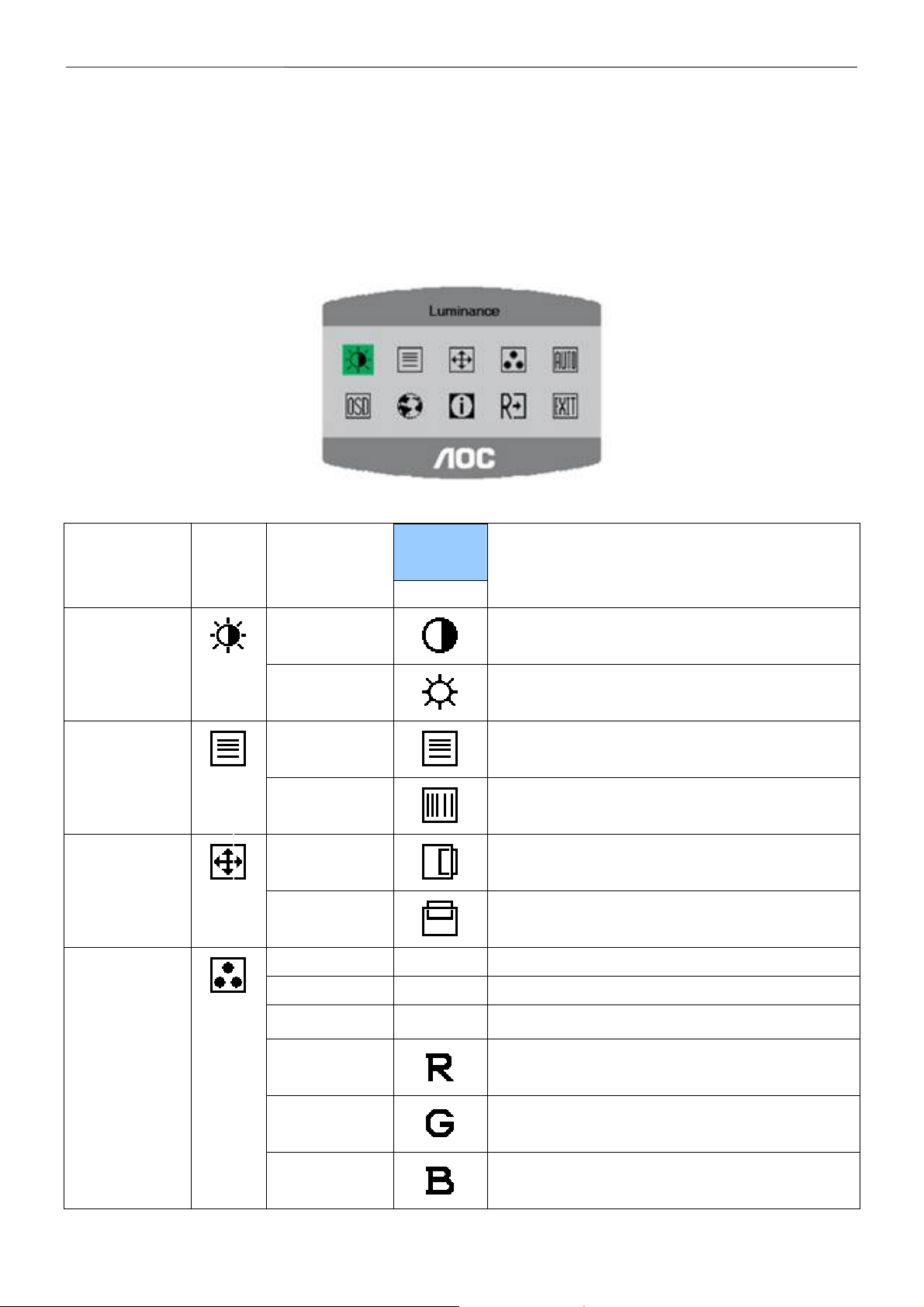
3.3 Adjusting The Pictures
1. Press the MENU-button to activate the OSD window.
2. Press
< or > to navigate through the functions. Once the desired function is highlighted, press the MENU-button
to activate it. If the function selected has a sub-menu, press
< or >again to navigate through the sub-menu
Functions. Once the desired function is highlighted, press MENU-button to activate it.
3. Press
< or > to change the settings of the selected function.
4. To exit and save, select the exit function. If you want to adjust any other function, repeat steps 2-3.
The table below describes the function of each OSD icon.
Main
Menu
Item
Main
Menu Icon
Sub
Menu
Item
Sub Menu
Icon
Description
Image Setup
Image Position
Color Temp.
Contrast
Brightness
Focus
Clock
H. Position
V. Position
Warm N/A Recall Warm Color Temperature from EEPROM.
Cool N/A Recall Cool Color Temperature from EEPROM.
sRGB N/A Recall sRGB Temperature from EEPROM.
User / Red
Contrast from Digital-register. Luminance
Backlight Adjustment
Adjust Picture Phase to reduce Horizontal-Line noise
Adjust picture Clock to reduce Vertical-Line noise.
Adjust the horizontal position of the picture.
Adjust the verticalposition of the picture.
Red Gain from Digital-register.
User / Green
User / Blue
Green Gain Digital-register.
Blue Gain from Digital-register.
8
17" LCD Color Monitor AOC 712Si
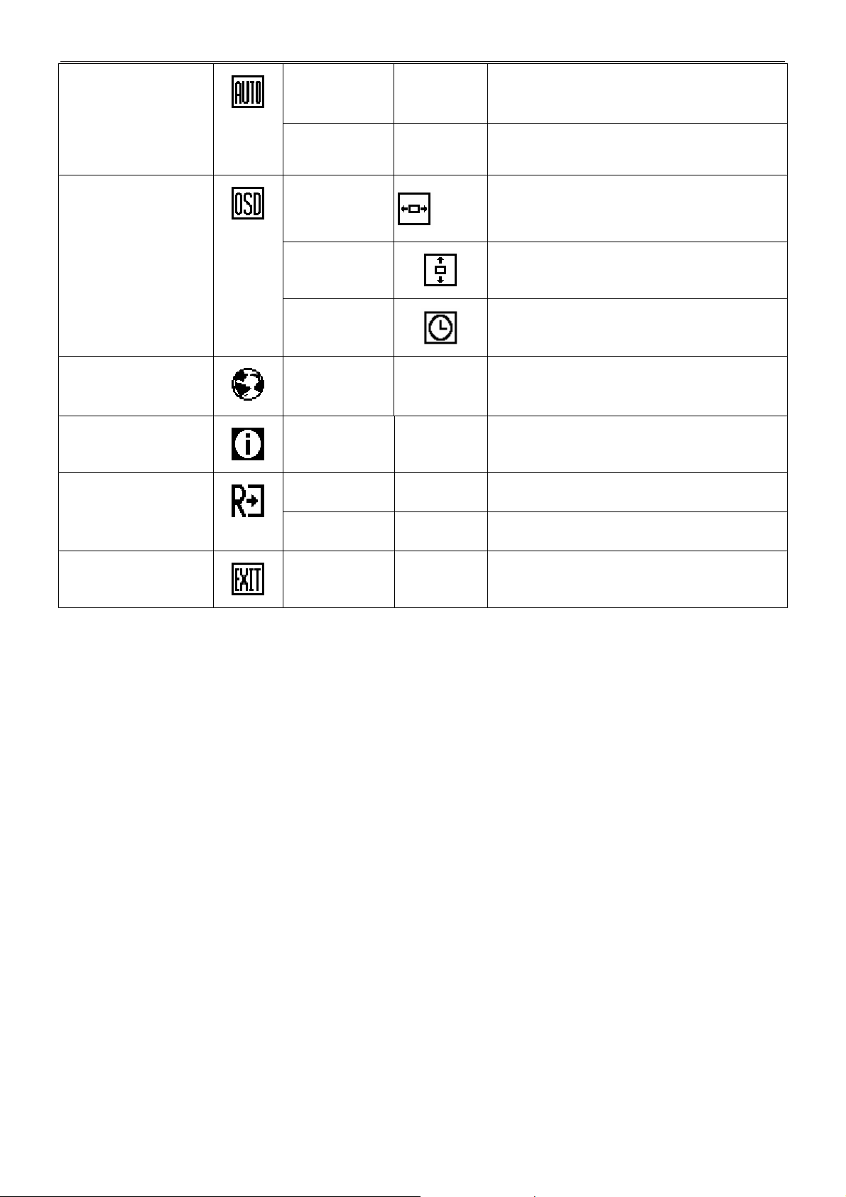
Auto Config
OSD Setup
Language
Information
Yes
No N/A Do not execute Auto Config, return to main menu.
H. Position
V. Position
OSD Timeout
Language N/A
Information N/A Show the resolution, H/V frequency and input port of
Yes N/A Clear each old status of Auto-configuration. Reset
N/A Auto Adjust the H/V Position, Focus and Clock of
picture.
Adjust the horizontal position of the OSD.
Adjust the verticalposition of the OSD.
Adjust the OSD timeout.
Set OSD language
current input timing.
Exit
No N/A Do not execute reset, return to main menu.
N/A N/A Exit OSD
9
17" LCD Color Monitor AOC 712Si
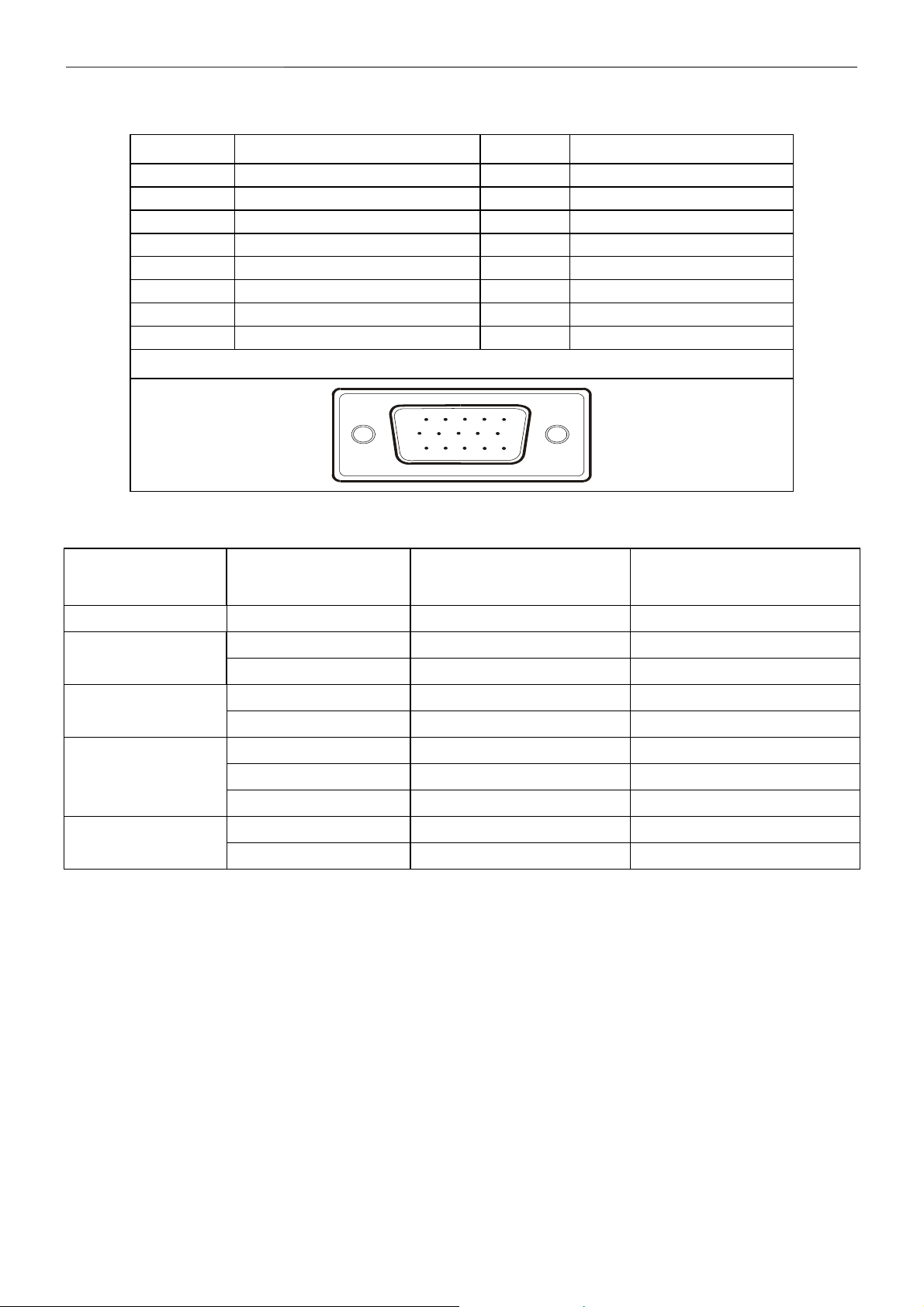
4. Input/Output Specification
4.1 D-SUB connector
Pin No. Description Pin No. Description
1. Red 9. +5V
2. Green 10. Detect Cable
3. Blue 11. TXD
4. RXD 12. DDC-Serial Data
5. Ground 13. H-Sync
6. R-Ground 14. V-Sync
7. G-Ground 15. DDC-Serial Clock
8. B-Ground
VGA Connector layout
15
6
11 15
10
4.2 Factory Preset Display Modes
STANDARD
Dos-mode 720 x 400 31.47kHz 70.0Hz
VGA
SVGA
XGA
SXGA
RESOLUTION
640 × 480 31.47kHz 60.0Hz
640 × 480 37.50kHz 75.0Hz
800 × 600 37.879kHz 60.0Hz
800 × 600 46.875kHz 75.0Hz
1024 × 768 48.363kHz 60.0Hz
1024 × 768 56.476kHz 70.0Hz
1024 × 768 60.021kHz 75.0Hz
1280 × 1024 64.000kHz 60.0Hz
1280 × 1024 80.000kHz 75.0Hz
HORIZONTAL
FREQUENCY
VERTICAL
FREQUENCY
10
17" LCD Color Monitor AOC 712Si
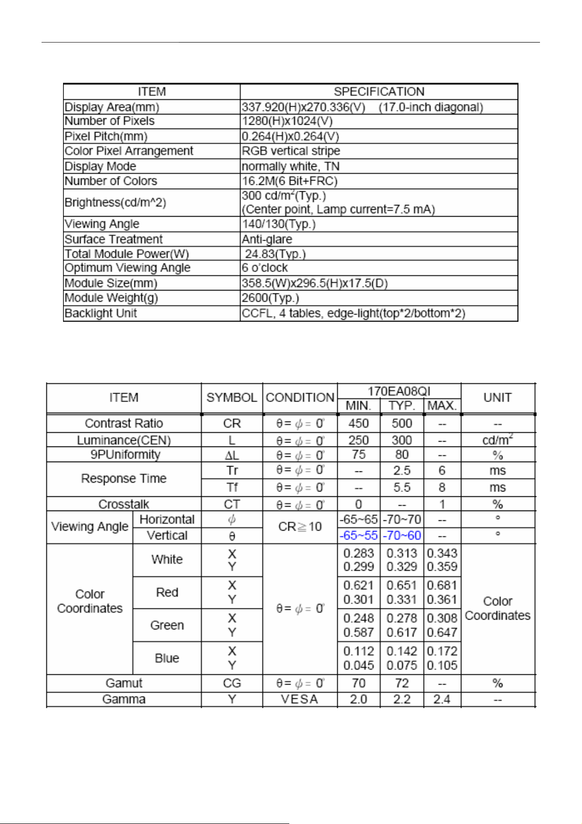
5. Panel Specification
5.1 General Characteristics
5.2 Optical Characteristics
The optical characteristics are measured under stable conditions at 25±2 (Room Temperature)℃ :
11
17" LCD Color Monitor AOC 712Si
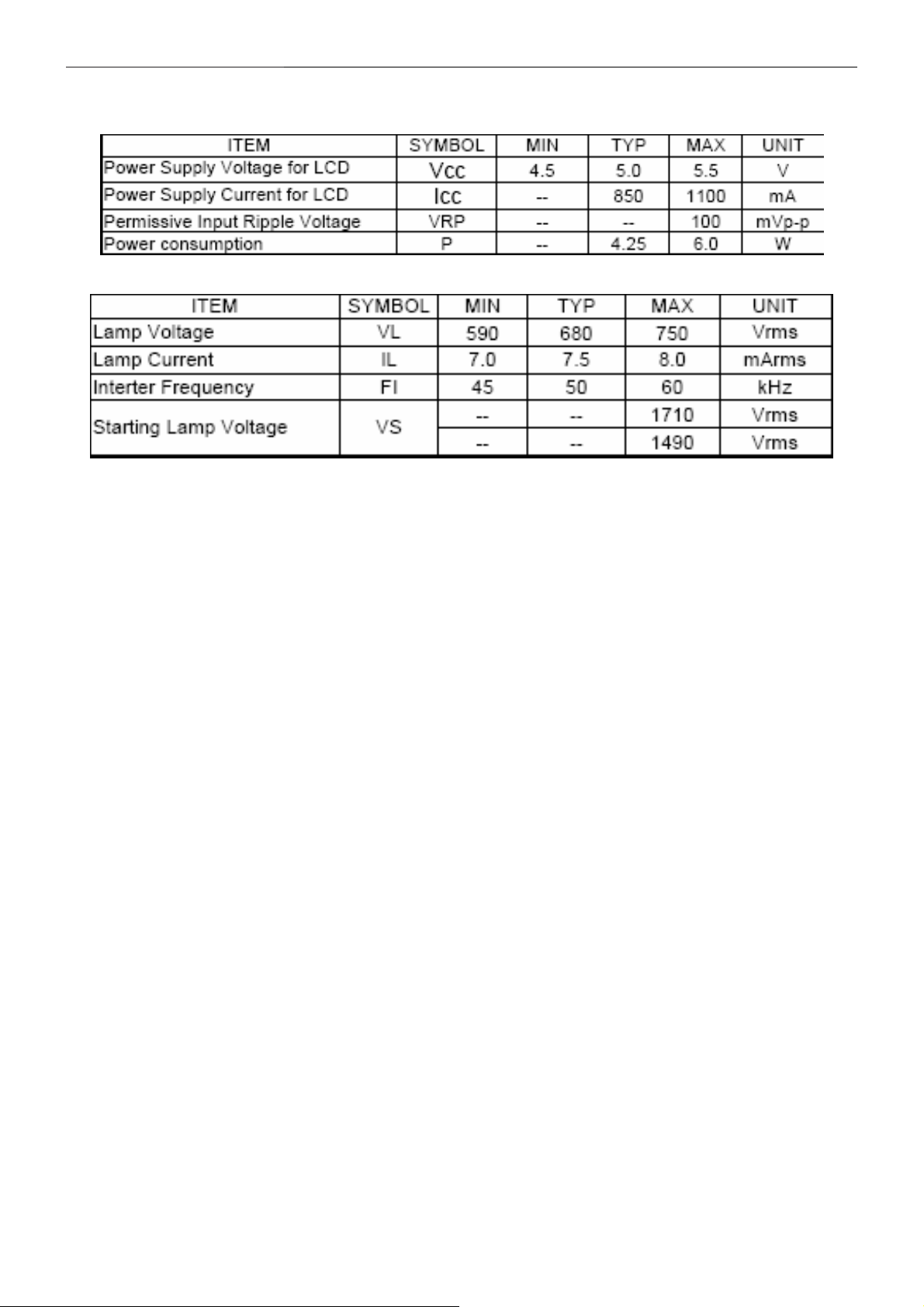
5.3 Electrical Characteristics
TFT LCD MODULE
BACKLIGHT UNIT
12
17" LCD Color Monitor AOC 712Si
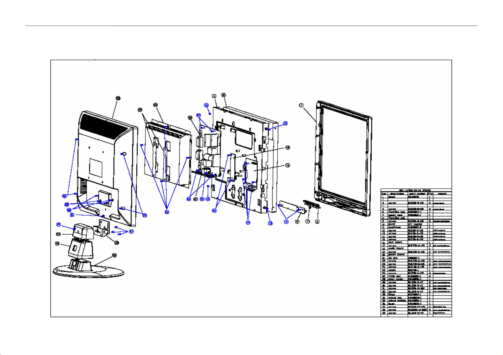
6. Block Diagram
6.1 Monitor Exploded View
13
17" LCD Color Monitor AOC 712Si
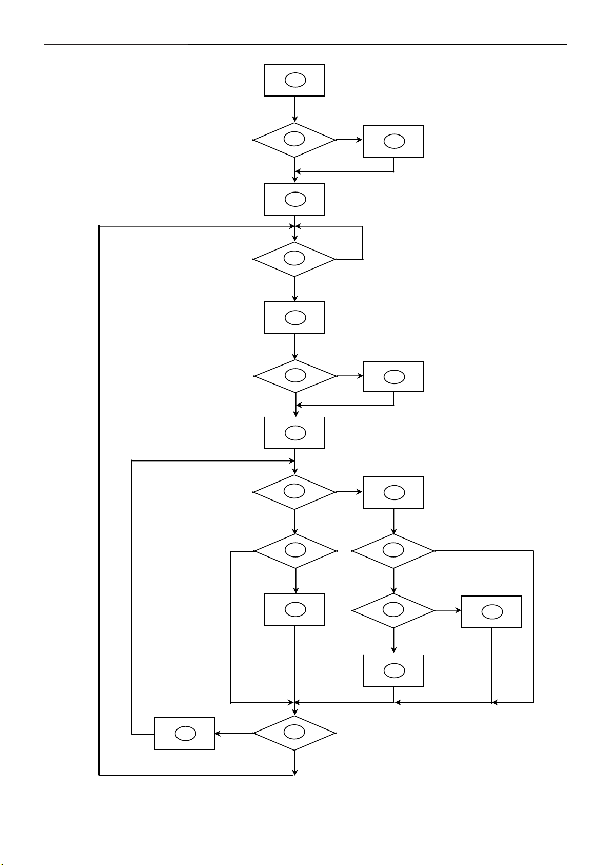
6.2 Software Flow Chart
1
2
N
4
5
Y
6
Y
N
3
N
10
12
14
7
Y
9
Y
Y
N
N
13
15
17
11
8
N
Y
N
Y
16
18
N
19
Y
14
17" LCD Color Monitor AOC 712Si
1) MCU initializes.
2) Is the EEPROM blank?
3) Program the EEPROM by default values.
4) Get the PWM value of brightness from EEPROM.
5) Is the power key pressed?
6) Clear all global flags.
7) Are the AUTO and SELECT keys pressed?
8) Enter factory mode.
9) Save the power key status into EEPROM. Turn on the LED and set it to green color. Scaler initializes.
10) In standby mode?
11) Update the lifetime of back light.
12) Check the analog port, are there any signals coming?
13) Does the scalar send out an interrupt request?
14) Wake up the scalar.
15) Are there any signals coming from analog port?
16) Display "No connection Check Signal Cable" message. And go into standby mode after the message
disappears.
17) Program the scalar to be able to show the coming mode.
18) Process the OSD display.
19) Read the keyboard. Is the power key pressed?
15
17" LCD Color Monitor AOC 712Si
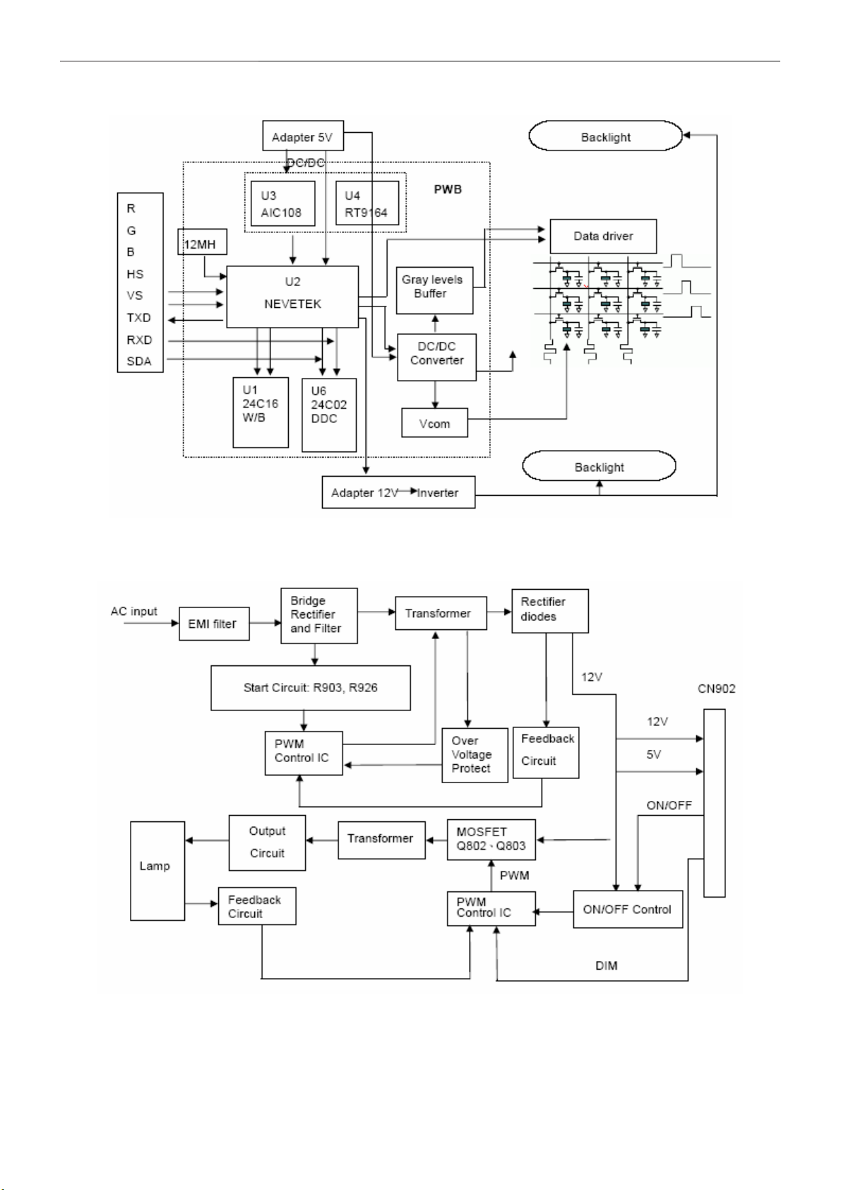
6.3 Electrical Block Diagram
6.3.1 Main Board
6.3.2 Inverter/Power Board
16
17" LCD Color Monitor AOC 712Si
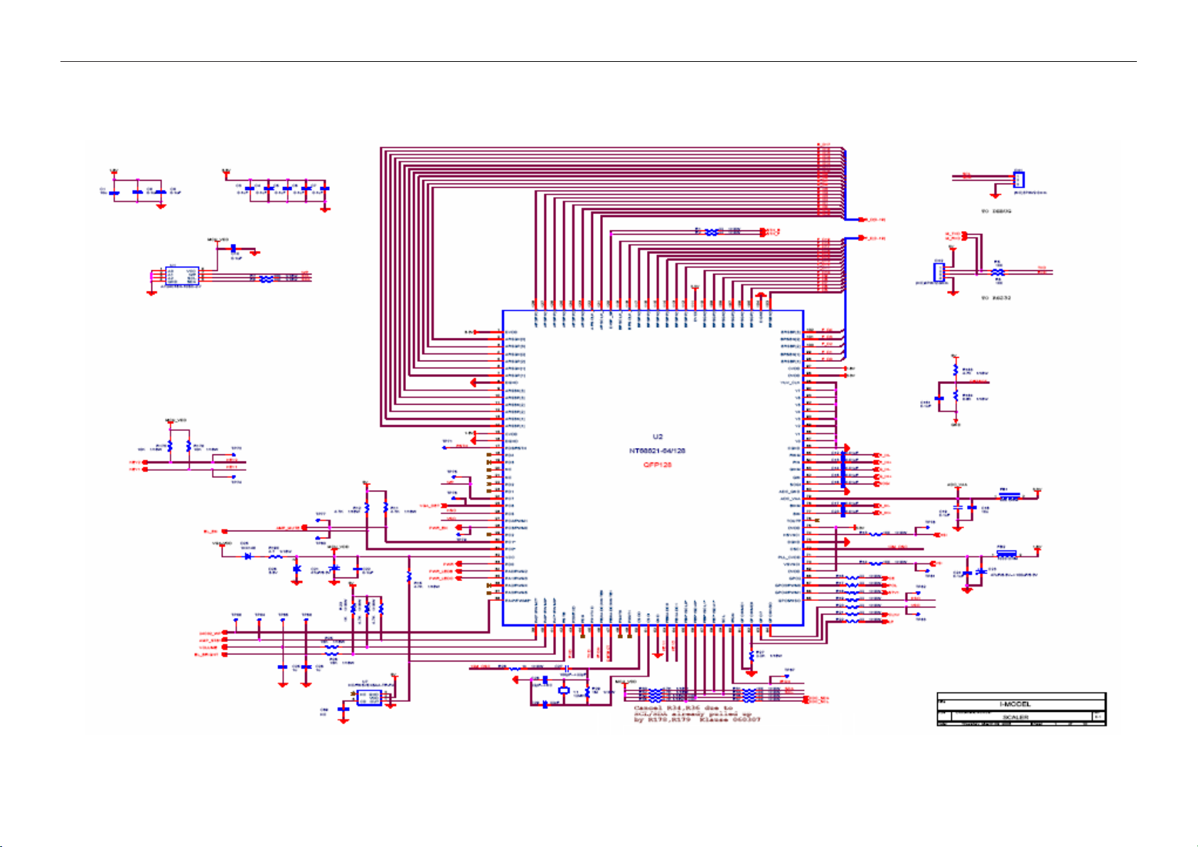
7. Schematic
7.1 Main Board
17
17" LCD Color Monitor AOC 712Si
18

17" LCD Color Monitor AOC 712Si
19

17" LCD Color Monitor AOC 712Si
20

17" LCD Color Monitor AOC 712Si
21

17" LCD Color Monitor AOC 712Si
22

17" LCD Color Monitor AOC 712Si
23

17" LCD Color Monitor AOC 712Si
24

17" LCD Color Monitor AOC 712Si
25

17" LCD Color Monitor AOC 712Si
26

17" LCD Color Monitor AOC 712Si
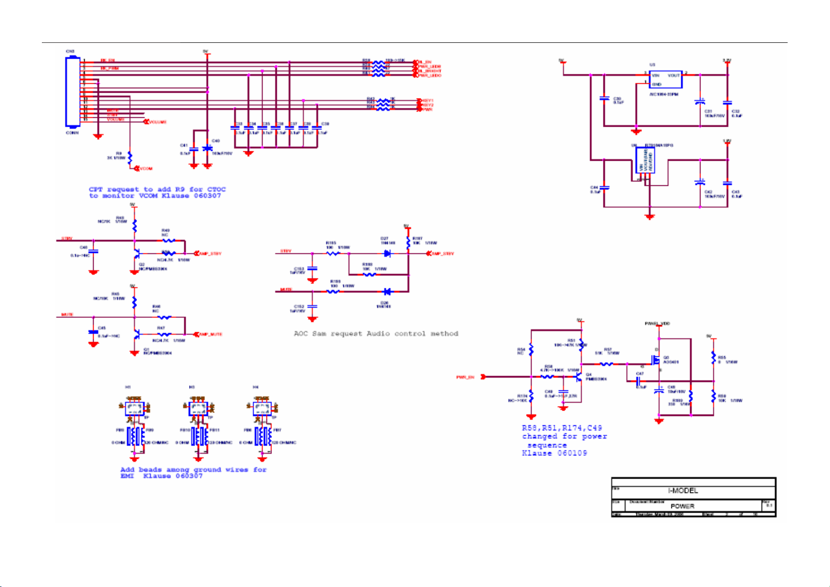
7.2 Inverter/ Power Board
27

17" LCD Color Monitor AOC 712Si
28

17" LCD Color Monitor AOC 712Si
8. PCB Layout
8.1 Main Board
29

17" LCD Color Monitor AOC 712Si
8.2 Power Board
30

17" LCD Color Monitor AOC 712Si
31

17" LCD Color Monitor AOC 712Si
8.3 Key Board
32

17" LCD Color Monitor AOC 712Si
9. Maintainability
9.1 Equipment and Tools Requirement
1. Voltmeter.
2. Oscilloscope.
3. Pattern Generator.
4. DDC Tool with an IBM Compatible Computer.
5. Alignment Tool.
6. LCD Color Analyzer.
7. Service Manual.
8. User Manual.
33

17" LCD Color Monitor AOC 712Si
9.2 Trouble Shooting
9.2.1 Main Board
No Power (No LED indicator)
Rewrite SW
Check U3, U4=5v
OK
Check U2 supply voltage
OK
Check key circuit if ok
OK
Check U2 (pin PWR、RST )
NG
NG
NG
NG
Check U2、U3
and U4 if OK
NG
Check adapter and
connector
Change defective
NG
Change defective
component
Change defective component
34

17" LCD Color Monitor AOC 712Si
g
p
pply
No Picture (LED green)
The button under
control
NG
Check U2、pin50 and pin51
waveforms
NG
Change U2
No picture(LED orange)
The button under
control
NG
OK
Check U2 BL EN is
hi
h voltage
Change U2
OK
Check reset signal
of U2、
NG
Change defective
in17
OK
Check C29 and
NG
NG
Change U2
Analyse inverter
OK
Check waveforms of
U2、pin50 and pin51
NG
Check Y1、C29
su
voltage
NG
Change defective
OK
Check U2 supply voltage
NG
Change defective component
OK
Check VGA、HS、VS signal
NG
Check if under saving mode
OK
Check U2、pin70、pin74
NG
Check U5
NG
Change U5
NG
Change U2
35

17" LCD Color Monitor AOC 712Si
No Use Of Pressing Key button
Check key circuit
is normal
NG
Check C33、C38 and C39
OK
Check U2、pin33、34、35
are defective
NG
Change U2 or solder
solder or bad
White Screen
Check PWR_EN is
high voltage
OK
NG
NG
Change defective component
Change U2
Check L1 supply voltage
Check output of Pin4 from IC3
OK
OK
Check D21 voltage is normal
after adjusting current
OK
Change Q6
NG
NG
Change Q3、L1
Pin 6 oscillate is
normal
OK
Check pin1、pin2 is high voltage
NG
Check C82/C85/IC3
NG
Change defective component
NG
Check C81
Check IC3
OK
NG
Change C81
36

17" LCD Color Monitor AOC 712Si
OSD is normal when on signal, no picture when connect signal (black screen)
Check pin70、pin74 H/V
sync signal is OK
OK
Change U2
Miss color
Check the missing color,
the input
OK
NG
Change defective component
Check VGA、
HS、VS
OK
Check U5、D15、D16、
C55、C56
NG
NG
Check signal
connector if OK
OK
NG
Change signal
connector
NG
Check signal
source
Change signal
connector connecter
Check U2 pin77 pin82
pin84,
NG
R fail G fail B fail
Check D14、
R69、C52
Check D10、
R66 and C51
OK
check U2
Check D6、
R61 and
37

17" LCD Color Monitor AOC 712Si
Picture shake
Check Vcom=4.35V
signal of which is normal
NG
If VR1 adjust to Vcom by hand
NG
Check VDDA if normal
NG
Check D21、Q6
NG
Change defective
Adjust picture to normal
Change VR1
38

17" LCD Color Monitor AOC 712Si
9.2.2 Power Board
Check F801= 12V
NG
Check AC line volt 110V or 220V
OK
NG
Check AC input
Check the voltage of C907 (+)
NG
OK
Check bridge rectified circuit and F901
circuit
Check start voltage for the pin8 of IC901
OK
NG
Check R903 Change IC901
Check the auxiliary voltage is bigger than
10V and smaller than 20V
OK
NG
1) Check IC901
2) Check R904/D903 circuit
Check IC901 pin7 PWM wave
OK
NG
Check IC901
Check Q901/D901/D904/ZD901
39

17" LCD Color Monitor AOC 712Si
2.) No Backlight
Check F801=12V
NG
Check adapter and F801
OK
Check ON/OFF signal
NG
OK
Check U201 pin9=12V
NG
OK
Check IC801 PIN2=5V
NG
OK
Check IC201 PIN13 have triangle wave
NG
Check Interface board or
Change Q201 or Q202
Change on/off circuit
Change U201
OK
Check IC201 PIN1/PIN15 PWM wave
NG
OK
Check Q802/Q803 Drain wave
NG
OK
Check the output of PT801
NG
OK
Check connecter & lamp
Check Q802/Q803
Check Q802/Q803
Change PT801
40

17" LCD Color Monitor AOC 712Si
9.2.3 Key Board
OSD is unstable or not working
Is Keypad Board connecting normally?
Y
Is Button Switch normally?
Y
Is Keypad Board Normally?
Y
Check Main Board
N
Connect Keypad Board
N
Replace Button Switch
N
Replace Keypad Board
41

17" LCD Color Monitor AOC 712Si
10. White- Balance, Luminance Adjustment
Approximately 30 minutes should be allowed for warm up before proceeding White-Balance adjustment.
1. How to do the Chroma-7120 MEM. Channel setting
A. Reference to chroma 7120 user guide
B. Use “ SC” key and “ NEXT” key to modify x, y, Y value and use “ID” key to modify the
TEXT description Following is the procedure to do white-balance adjust
2. Setting the color temp. you want
A. MEM.CHANNEL 3 (7800 color):
7800 color temp. parameter is x = 296 ±20, y = 311 ±20, Y = 180 cd/m
B. MEM.CHANNEL 4 (6500 color):
6500 color temp. parameter is x = 313±20, y = 329 ±20, Y =180 cd/m2
3. Into factory mode of 712Si
Turn on power, press the MENU button, pull out the power cord, and then plug the power cord. Then the factory
OSD will be at the left top of the panel.
2 ,
4. Bias adjustment:
Set the Contrast
to 50; Adjust the Brightness to 90.
5. Gain adjustment:
Move cursor to “-F-” and press MENU key
A. Adjust C2 (7800) color-temperature
1. Switch the Chroma-7120 to RGB-Mode (with press “MODE” button)
2. Switch the MEM. Channel to Channel 3 (with up or down arrow on chroma 7120)
3. The LCD-indicator on chroma 7120 will show x = 296 ±20, y = 311 ±20, Y =180 cd/m
2
4. Adjust the RED of color1 on factory window until chroma 7120 indicator reached the value R=100
5. Adjust the GREEN of color1 on factory window until chroma 7120 indicator reached the value G=100
6. Adjust the BLUE of color1 on factory window until chroma 7120 indicator reached the value B=100
7. Repeat above procedure (item 4,5,6) until chroma 7120 RGB value meet the tolerance =100±5
B. Adjust C1 (6500) color-temperature
1. Switch the chroma-7120 to RGB-Mode (with press “MODE” button)
2. Switch the MEM.channel to Channel 4(with up or down arrow on chroma 7120)
3. The LCD-indicator on chroma 7120 will show x = 313 ±20, y = 329 ±20, Y = 180 cd/m
2
4. Adjust the RED of color3 on factory window until chroma 7120 indicator reached the value R=100
5. Adjust the GREEN of color3 on factory window until chroma 7120 indicator reachedthe value G=100
6. Adjust the BLUE of color3 on factory window until chroma 7120 indicator reached the value B=100
7. Repeat above procedure (item 4,5,6) until chroma 7120 RGB value meet the tolerance =100±5
C. Turn the Power-button off to quit from factory mode.
42

17" LCD Color Monitor AOC 712Si
11. BOM List
T77CNNNKHAA1FIE
Location Part No. Description
KEPC7HA4 KEY BOARD
PWPC1741CE2P POWER BOARD
15G8266 1 AC BKT
26G 800504 7 BARCODE
40G 58162435A MANUAL LABEL
41G780061532C SA CENTER LIST
50G 600 2 HANDLE1
50G 600 3 HANDLE2
52G 1185 MIDDLE TAPE
52G 1186 SMALL TAPE
52G6020 11 PROTECT FILM
85G 721 1 SHIELD
E089A 89G 745HAA 1 SIGNAL CABLE HONGLIN
89G402A15N IS POWER CORD
M1G 330 4128 CR3 SCREW M3X4
M1G 330 6 47 CR3 SCREW 3X6mm
M1G 340 6 47 CR3 SCREW
M1G 340 8225 CR3 SCREW 4*8mm
M1G1130 6128 CR3 SCREW
M1G1140 6128 CR3 SCREW
M1G1730 6128 CR3 SCREW M3x6
Q1G 330 8128 CR3 SCREW 3X8mm
705GH734008 ASS'Y
750GLV70M8Q61V PANEL CLAA170EA08QI 000
A15G0028 1 VESA BKT
A33G0030 GM 1L 32 CABLE COVER
A33G0060 1 POWER LENS
A33G0067 Q1 L KEY PAD
A34G0095 Q1Z9B 30 BEZEL
A34G0096 GMZAB REAR COVER
H40G 17N61537A ID LABEL
H41G170061533B MANUAL
H44G700761530A CARTON
H45G 87 1 2H R PE BAG FOR MONITOR
H45G 87 4 H R PE BAG FOR BASE
H45G 87 4 H R PE BAG FOR BASE
H52G6025 16006 INSULATE SHEET
43

17" LCD Color Monitor AOC 712Si
J44G7007 1 EPS
J44G7007 2 EPS
Q15G0022 2 HINGE BRACKET
Q45G 88606 14 R PE BAG
CN001 33G8027 12 H PIN HEADER 2*6 R/A
SW001 77G 600 1GCJ TACT SWITCH TSPB-2
SW002 77G 600 1GCJ TACT SWITCH TSPB-2
SW003 77G 600 1GCJ TACT SWITCH TSPB-2
SW004 77G 600 1GCJ TACT SWITCH TSPB-2
SW005 77G 600 1GCJ TACT SWITCH TSPB-2
DP001 81G 12 2 GP LED
R009 61G0603103 RST CHIPR 10KOHM +-5% 1
R011 61G0603103 RST CHIPR 10KOHM +-5% 1
C002 65G0603104 12 0.1UF +-10% 16V X7R
C003 65G0603104 12 0.1UF +-10% 16V X7R
C004 65G0603104 12 0.1UF +-10% 16V X7R
C005 65G0603104 12 0.1UF +-10% 16V X7R
C001 65G0603105 12 CHIP 1UF 16VX7R 0603
D001 93G 39S 34 T UDZS5.6B
D002 93G 39S 34 T UDZS5.6B
715G2253 1 2 KEY BOARD PCB
L901 S73L17450VH LINE FILTER
CN801 33G8021 2E U WAFER
CN802 33G8021 2E U WAFER
CN803 33G8021 2E U WAFER
CN804 33G8021 2E U WAFER
40G 45762420A ID LABEL
IC902 56G 139 3A PC123Y22FZOF
NR901 61G 58080 WT RST NTCR 8 OHM
R924 61G152M10464L RST MOFR 100KOHM +-5% 2
R912 61G152M278 64 RST MOFR 0.27 OHM +-5%
C908 63G 10747410V CAP X2 0.47UF M 275VAC
C805 65G 3J1006ET H TDK 10PF +-5% 3KV
C809 65G 3J1006ET H TDK 10PF +-5% 3KV
C801 65G 3J5096ET H 5PF 5% 3KV TDK
C811 65G 3J5096ET H 5PF 5% 3KV TDK
C900 65G305M1022BP Y2 1000PF M 250VAC Y5P
C901 65G305M1022BP Y2 1000PF M 250VAC Y5P
C902 65G306M4722BP 4700PF +-20% 400VAC
C904 67G215S1023KV ELCAP 1000UF +-20% 16V
44
17" LCD Color Monitor AOC 712Si
C905 67G215S1023KV ELCAP 1000UF +-20% 16V
C910 67G215S1023KV ELCAP 1000UF +-20% 16V
C911 67G215S1023KV ELCAP 1000UF +-20% 16V
C802 67G215S4713KV ELCAP 470UF +-20% 16V 1
C906 67G215S4713KV ELCAP 470UF +-20% 16V 1
C912 67G215S4713KV ELCAP 470UF +-20% 16V 1
C907 67G215Z12115K ELCAP 120UF +-20% 450V
L902 73G 174 65 H LINE FILTER
L905 73G 253 91 H CHOKE COIL
L903 73G 253 91 LS CHOKE BY LI SHIN
PT801 80GL17T 34 DN XFMR BY DARFON
T901 80GL17T 35 DN XFMR FOR POWER DARFON
CN901 87G 501 32 S AC SOCKET
CN902 95G8014 15506 WIRE HARNESS
CN903 95G801412X607 WIRE HARNESS
Q51G 6 4508 RTV
BD901 93G 50460509 2KBP06M 2A 600V
D904 93G3010 1 31DQ10FC
705G 780 57 54 Q901 ASS'Y
705G 780 93 16 D901 ASS'Y
IC901 56G 564911 IC TEA1532AT S08
IC801 56G 608 10 OZ9938GN
Q801 57G 417 4 PMBS3904/PHILIPS-SMT(04
Q806 57G 417 4 PMBS3904/PHILIPS-SMT(04
Q811 57G 417 4 PMBS3904/PHILIPS-SMT(04
Q804 57G 417 6 PMBS3906/PHILIPS-SMT(06
Q812 57G 417 6 PMBS3906/PHILIPS-SMT(06
Q802 57G 600 61 AM4502C-TI-PF S0-8
Q803 57G 600 61 AM4502C-TI-PF S0-8
Q807 57G 759 2 RK7002
Q810 57G 759 2 RK7002
Q808 57G 760 4B PDTA144WK SOT346
Q805 57G 760 5B PDTC144WK SOT346
R921 61G0805000 RST CHIPR 0 OHM +-5% 1/
R922 61G0805000 RST CHIPR 0 OHM +-5% 1/
R906 61G0805100 RST CHIPR 10 OHM +-5% 1
R909 61G0805100 1F RST CHIPR 1KOHM +-1% 1/
R804 61G0805102 RST CHIPR 1KOHM +-5% 1/
R918 61G0805102 RST CHIPR 1KOHM +-5% 1/
R919 61G0805102 RST CHIPR 1KOHM +-5% 1/
45

17" LCD Color Monitor AOC 712Si
R832 61G0805103 RST CHIPR 10KOHM +-5% 1
R907 61G0805103 RST CHIPR 10KOHM +-5% 1
R803 61G0805104 RST CHIPR 100KOHM +-5%
R813 61G0805104 RST CHIPR 100KOHM +-5%
R820 61G0805104 RST CHIPR 100KOHM +-5%
R823 61G0805105 RST CHIPR 1MOHM +-5% 1/
R826 61G0805105 RST CHIPR 1MOHM +-5% 1/
R830 61G0805105 RST CHIPR 1MOHM +-5% 1/
R910 61G0805123 RST CHIPR 12KOHM +-5% 1
R829 61G0805124 RST CHIPR 120KOHM +-5%
R828 61G0805150 1F RST CHIPR 1.5KOHM +-1%
R920 61G0805150 2F RST CHIPR 15KOHM +-1% 1
R802 61G0805152 RST CHIPR 1.5KOHM +-5%
R835 61G0805152 RST CHIPR 1.5KOHM +-5%
R807 61G0805153 RST CHIPR 15KOHM +-5% 1
R818 61G0805153 RST CHIPR 15KOHM +-5% 1
R810 61G0805220 RST CHIPR 22 OHM +-5% 1
R827 61G0805221 RST CHIPR 220 OHM +-5%
R915 61G0805300 2F RST CHIPR 30KOHM +-1% 1
R917 61G0805390 1F RST CHIPR 3.9KOHM +-1%
R824 61G0805390 2F RST CHIPR 39KOHM +-1% 1
R911 61G0805472 RST CHIPR 4.7KOHM +-5%
R916 61G0805510 1F RST CHIPR 5.1KOHM +-1%
R923 61G0805510 1F RST CHIPR 5.1KOHM +-1%
R808 61G0805511 RST CHIPR 510 OHM +-5%
R831 61G0805514 RST CHIPR 510KOHM +-5%
R801 61G0805561 RST CHIPR 560 OHM +-5%
R812 61G0805561 RST CHIPR 560 OHM +-5%
R819 61G0805564 RST CHIPR 560KOHM +-5%
R816 61G0805822 RST CHIPR 8.2KOHM +-5%
R821 61G0805822 RST CHIPR 8.2KOHM +-5%
R837 61G0805911 RST CHIPR 910 OHM +-5%
R838 61G0805911 RST CHIPR 910 OHM +-5%
RJ801 61G1206000 RST CHIPR 0 OHM +-5% 1/
RJ802 61G1206000 RST CHIPR 0 OHM +-5% 1/
RJ803 61G1206000 RST CHIPR 0 OHM +-5% 1/
F801 61G1206000 4 RST CHIPR 0 OHM +-5% 1/
R914 61G1206204 RST CHIPR 200KOHM +-5%
R825 61G1206564 RST CHIPR 560KOHM +-5%
R900 61G1206684 RST CHIPR 680KOHM +-5%
46

17" LCD Color Monitor AOC 712Si
R901 61G1206684 RST CHIPR 680KOHM +-5%
R902 61G1206684 RST CHIPR 680KOHM +-5%
R904 61G1206759 RST CHIPR 7.5 OHM +-5%
C810 65G0805102 31 1000PF 50V NPO
C812 65G0805102 31 1000PF 50V NPO
C822 65G0805102 31 1000PF 50V NPO
C922 65G0805102 31 1000PF 50V NPO
C819 65G0805103 32 10NF/50V/0805/X7R
C820 65G0805103 32 10NF/50V/0805/X7R
C916 65G0805104 22 0.1UF +-10% 25V X7R 080
C806 65G0805104 32 CHIP 0.1U 50V X7R
C807 65G0805104 32 CHIP 0.1U 50V X7R
C824 65G0805104 32 CHIP 0.1U 50V X7R
C917 65G0805104 32 CHIP 0.1U 50V X7R
C921 65G0805104 32 CHIP 0.1U 50V X7R
C919 65G0805224 22 CAIP CAP 0.22 uF 25V X7
C815 65G0805225 27 2.2UF
C823 65G0805225 27 2.2UF
C804 65G0805471 31 CHIP 470PF 50V NPO
C814 65G0805471 31 CHIP 470PF 50V NPO
C817 65G0805471 31 CHIP 470PF 50V NPO
C821 65G0805473 32 CHIP 0.047UF 50V X7R
C818 65G0805682 32 CHIP 6.8nF 50V X7R 0805
C816 65G0805683 22 MLCC 0805 68NF 25V X7R
D803 93G 64 42 P BAV70 SOT-23
D804 93G 64 42 P BAV70 SOT-23
D905 93G 6432S 1N4148W
D801 93G 6433P BAV99
D802 93G 6433P BAV99
ZD902 93G 39S 17 T RLZ12B LLDS
ZD801 93G 39S 24 T RLZ 5.6B LLDS
ZD903 93G 39S 25 T RLZ5.1B BY ROHM
ZD901 93G 39S 38 T PTZ 9.1B
CN901 6G 31500 EYELET
C907 6G 31502 1.5MM RIVET
L901 6G 31502 1.5MM RIVET
L902 6G 31502 1.5MM RIVET
PT801 6G 31502 1.5MM RIVET
Q901 6G 31502 1.5MM RIVET
T901 6G 31502 1.5MM RIVET
47

17" LCD Color Monitor AOC 712Si
C914 65G517K102 5T6921 1000PF +-10% 500V Y5P
C915 65G517K102 5T6921 1000PF +-10% 500V Y5P
F901 84G 55 7W FUSE 3.15A 250V WICKMAN
715G1696 3 POWER BOARD PCB
J1 95G 90 23 TINCOATEDCOPPER
J304 95G 90 23 TINCOATEDCOPPER
J305 95G 90 23 TINCOATEDCOPPER
J307 95G 90 23 TINCOATEDCOPPER
J309 95G 90 23 TINCOATEDCOPPER
J310 95G 90 23 TINCOATEDCOPPER
J801 95G 90 23 TINCOATEDCOPPER
J802 95G 90 23 TINCOATEDCOPPER
J803 95G 90 23 TINCOATEDCOPPER
J804 95G 90 23 TINCOATEDCOPPER
J805 95G 90 23 TINCOATEDCOPPER
J806 95G 90 23 TINCOATEDCOPPER
J807 95G 90 23 TINCOATEDCOPPER
J808 95G 90 23 TINCOATEDCOPPER
J809 95G 90 23 TINCOATEDCOPPER
J810 95G 90 23 TINCOATEDCOPPER
J811 95G 90 23 TINCOATEDCOPPER
J812 95G 90 23 TINCOATEDCOPPER
J813 95G 90 23 TINCOATEDCOPPER
J814 95G 90 23 TINCOATEDCOPPER
J815 95G 90 23 TINCOATEDCOPPER
J816 95G 90 23 TINCOATEDCOPPER
J817 95G 90 23 TINCOATEDCOPPER
J901 95G 90 23 TINCOATEDCOPPER
J902 95G 90 23 TINCOATEDCOPPER
J903 95G 90 23 TINCOATEDCOPPER
J904 95G 90 23 TINCOATEDCOPPER
J905 95G 90 23 TINCOATEDCOPPER
J906 95G 90 23 TINCOATEDCOPPER
J907 95G 90 23 TINCOATEDCOPPER
J908 95G 90 23 TINCOATEDCOPPER
R833 95G 90 23 TINCOATEDCOPPER
R834 95G 90 23 TINCOATEDCOPPER
R908 61G 17218252T RST CFR 1.8K0HM +-5% 1/
R806 61G 17247152T RST CFR 470 0HM +-5% 1/
R905 61G 20747052T RST MOFR 47 OHM +-5% 1/
48

17" LCD Color Monitor AOC 712Si
R913 61G 20747052T RST MOFR 47 OHM +-5% 1/
R836 61G 60251152T RST CFR 510 OHM +-5% 1/
R903 61G212Y15352T RST MGFR 15KOHM +-5% 1/
R809 61G212Y625 KT RST MGFR 6.2MOHM +-5% 1
R814 61G212Y625 KT RST MGFR 6.2MOHM +-5% 1
C923 64G700J1040AT 0.1UF 50V PEN
D902 93G 6026T52T RECTIFIER DIODE FR107
D903 93G 6038P52T PS102R
IC903 56G 158 4 T H431BA
C918 65G 2K152 1T6052 1.5NF/2KV Y5P+-10%
C920 67G 2151097NT ELCAP 1UF +-20% 50V 105
C909 67G 305100 7T ELCAP 10UF +-20% 50V 10
Q901 57G 667 21 STP10NK70ZFP
90G6263 1 HEAT SINK
M1G1730 8128 CR3 SCREW
90G6263 1 HEAT SINK
D901 93G 60245 SP10150
M1G1730 8128 CR3 SCREW
A34G0053 GM 1B STAND TOP
A34G0054 GM 1B STAND BOTTOM
A34G0097 GM 1B 33 BASE
A37G0007 9 HINGE
AQ1G1740 12120 SCREW
BOM For PWB
SMTC6CNNACH1
Location Part No. Description
CN3 33G802315A H WAFER
CN4 33G802315A H WAFER
40G 457624 1B CPU LABEL
IC3 56G 379 64 CT1102
U2 56G 562122 NT68621MEFG-64
U3 56G 563 75 G1084-33T43UF TO-252
IC2 56G 563 76 G960T63UF SOT-223
U4 56G 563 77 G952T43UF TO-252
IC1 56G 643 19 G675L240T1U
IC5 56G 663 2 AAT7205 SSOP-24
U1 56G1133 56 M24C16-WMN6TP
U6 56G113334A 24LC02B/SNG SOIC-8PIN
U5 56G4LVC 14 TI IC SN74LVC14APWR TSSOP-
49

17" LCD Color Monitor AOC 712Si
Q4 57G 417 4 PMBS3904/PHILIPS-SMT(04
Q5 57G 417 6 PMBS3906/PHILIPS-SMT(06
Q8 57G 417 6 PMBS3906/PHILIPS-SMT(06
Q9 57G 417 18 T PMBT3904 SOT-23
Q3 57G 763 1 AO3401L SOT23 BY AOS(A1
Q6 57G 763 21 MMC2301 SOT-23
Q7 57G 763 22 MMC2302 SOT-23
FB10 61G0603000 RST CHIPR 0 OHM +-5% 1/
FB6 61G0603000 RST CHIPR 0 OHM +-5% 1/
FB8 61G0603000 RST CHIPR 0 OHM +-5% 1/
R106 61G0603000 RST CHIPR 0 OHM +-5% 1/
R107 61G0603000 RST CHIPR 0 OHM +-5% 1/
R160 61G0603000 RST CHIPR 0 OHM +-5% 1/
R55 61G0603000 RST CHIPR 0 OHM +-5% 1/
R60 61G0603000 RST CHIPR 0 OHM +-5% 1/
R65 61G0603000 RST CHIPR 0 OHM +-5% 1/
R68 61G0603000 RST CHIPR 0 OHM +-5% 1/
R78 61G0603000 RST CHIPR 0 OHM +-5% 1/
R79 61G0603000 RST CHIPR 0 OHM +-5% 1/
R82 61G0603000 RST CHIPR 0 OHM +-5% 1/
R85 61G0603000 RST CHIPR 0 OHM +-5% 1/
R86 61G0603000 RST CHIPR 0 OHM +-5% 1/
R88 61G0603000 RST CHIPR 0 OHM +-5% 1/
R90 61G0603000 RST CHIPR 0 OHM +-5% 1/
R93 61G0603000 RST CHIPR 0 OHM +-5% 1/
R94 61G0603000 RST CHIPR 0 OHM +-5% 1/
R96 61G0603000 RST CHIPR 0 OHM +-5% 1/
R149 61G0603100 0F RST CHIPR 100 OHM +-1%
R150 61G0603100 0F RST CHIPR 100 OHM +-1%
R151 61G0603100 0F RST CHIPR 100 OHM +-1%
R152 61G0603100 0F RST CHIPR 100 OHM +-1%
R153 61G0603100 0F RST CHIPR 100 OHM +-1%
R154 61G0603100 0F RST CHIPR 100 OHM +-1%
R155 61G0603100 0F RST CHIPR 100 OHM +-1%
R156 61G0603100 0F RST CHIPR 100 OHM +-1%
R157 61G0603100 0F RST CHIPR 100 OHM +-1%
R158 61G0603100 0F RST CHIPR 100 OHM +-1%
R163 61G0603100 0F RST CHIPR 100 OHM +-1%
R164 61G0603100 0F RST CHIPR 100 OHM +-1%
R165 61G0603100 0F RST CHIPR 100 OHM +-1%
50

17" LCD Color Monitor AOC 712Si
R166 61G0603100 0F RST CHIPR 100 OHM +-1%
R167 61G0603100 0F RST CHIPR 100 OHM +-1%
R168 61G0603100 0F RST CHIPR 100 OHM +-1%
R169 61G0603100 0F RST CHIPR 100 OHM +-1%
R170 61G0603100 0F RST CHIPR 100 OHM +-1%
R171 61G0603100 0F RST CHIPR 100 OHM +-1%
R172 61G0603100 0F RST CHIPR 100 OHM +-1%
R63 61G0603100 1F RST CHIPR 1KOHM +-1% 1/
R13 61G0603101 RST CHIPR 100 OHM +-5%
R14 61G0603101 RST CHIPR 100 OHM +-5%
R180 61G0603101 RST CHIPR 100 OHM +-5%
R181 61G0603101 RST CHIPR 100 OHM +-5%
R185 61G0603101 RST CHIPR 100 OHM +-5%
R186 61G0603101 RST CHIPR 100 OHM +-5%
R31 61G0603101 RST CHIPR 100 OHM +-5%
R33 61G0603101 RST CHIPR 100 OHM +-5%
R35 61G0603101 RST CHIPR 100 OHM +-5%
R37 61G0603101 RST CHIPR 100 OHM +-5%
R5 61G0603101 RST CHIPR 100 OHM +-5%
R6 61G0603101 RST CHIPR 100 OHM +-5%
R62 61G0603101 RST CHIPR 100 OHM +-5%
R64 61G0603101 RST CHIPR 100 OHM +-5%
R67 61G0603101 RST CHIPR 100 OHM +-5%
R7 61G0603101 RST CHIPR 100 OHM +-5%
R70 61G0603101 RST CHIPR 100 OHM +-5%
R72 61G0603101 RST CHIPR 100 OHM +-5%
R73 61G0603101 RST CHIPR 100 OHM +-5%
R8 61G0603101 RST CHIPR 100 OHM +-5%
R23 61G0603102 RST CHIPR 1KOHM +-5% 1/
R28 61G0603102 RST CHIPR 1KOHM +-5% 1/
R42 61G0603102 RST CHIPR 1KOHM +-5% 1/
R43 61G0603102 RST CHIPR 1KOHM +-5% 1/
R44 61G0603102 RST CHIPR 1KOHM +-5% 1/
R174 61G0603103 RST CHIPR 10KOHM +-5% 1
R175 61G0603103 RST CHIPR 10KOHM +-5% 1
R176 61G0603103 RST CHIPR 10KOHM +-5% 1
R187 61G0603103 RST CHIPR 10KOHM +-5% 1
R188 61G0603103 RST CHIPR 10KOHM +-5% 1
R59 61G0603103 RST CHIPR 10KOHM +-5% 1
R97 61G0603103 RST CHIPR 10KOHM +-5% 1
51

17" LCD Color Monitor AOC 712Si
R162 61G0603104 RST CHIPR 100KOHM +-5%
R58 61G0603104 RST CHIPR 100KOHM +-5%
R80 61G0603104 RST CHIPR 100KOHM +-5%
R81 61G0603104 RST CHIPR 100KOHM +-5%
R83 61G0603104 RST CHIPR 100KOHM +-5%
R87 61G0603104 RST CHIPR 100KOHM +-5%
R99 61G0603104 RST CHIPR 100KOHM +-5%
R29 61G0603105 RST CHIPR 1MOHM +-5% 1/
R126 61G0603107 0F RST CHIPR 107 OHM +-1%
R137 61G0603107 0F RST CHIPR 107 OHM +-1%
R109 61G0603109 RST CHIPR 1 OHM +-5% 1/
R112 61G0603109 RST CHIPR 1 OHM +-5% 1/
R148 61G0603109 RST CHIPR 1 OHM +-5% 1/
R91 61G0603109 RST CHIPR 1 OHM +-5% 1/
R124 61G0603110 0F RST CHIPR 110 OHM +-1%
R130 61G0603110 1F RST CHIPR 1.1KOHM +-1%
R138 61G0603113 0F RST CHIPR 113 OHM +-1%
R127 61G0603130 1F RST CHIPR 1.3KOHM +-1%
R146 61G0603140 1F RST CHIPR 1.4KOHM +-1%
R120 61G0603150 9F RST CHIPR 15 OHM +-1% 1
R25 61G0603153 RST CHIPR 15KOHM +-5% 1
R26 61G0603153 RST CHIPR 15KOHM +-5% 1
R38 61G0603153 RST CHIPR 15KOHM +-5% 1
R95 61G0603169 0F RST CHIPR 169 OHM +-1%
R144 61G0603178 9F RST CHIPR 17.8 OHM +-1%
R136 61G0603180 0F RST CHIPR 180 OHM +-1%
R115 61G0603182 9F RST CHIPR 18.2 OHM +-1%
R123 61G0603191 1F RST CHIPR 1.91KOHM +-1%
R113 61G0603200 0F RST CHIPR 200 OHM +-1%
R1 61G0603220 RST CHIPR 22 OHM +-5% 1
R16 61G0603220 RST CHIPR 22 OHM +-5% 1
R17 61G0603220 RST CHIPR 22 OHM +-5% 1
R18 61G0603220 RST CHIPR 22 OHM +-5% 1
R19 61G0603220 RST CHIPR 22 OHM +-5% 1
R2 61G0603220 RST CHIPR 22 OHM +-5% 1
R20 61G0603220 RST CHIPR 22 OHM +-5% 1
R21 61G0603220 RST CHIPR 22 OHM +-5% 1
R22 61G0603220 RST CHIPR 22 OHM +-5% 1
R39 61G0603220 RST CHIPR 22 OHM +-5% 1
R41 61G0603220 RST CHIPR 22 OHM +-5% 1
52

17" LCD Color Monitor AOC 712Si
R116 61G0603220 9F RST CHIPR 22 OHM +-1% 1
R27 61G0603222 RST CHIPR 2.2KOHM +-5%
R74 61G0603222 RST CHIPR 2.2KOHM +-5%
R75 61G0603222 RST CHIPR 2.2KOHM +-5%
R145 61G0603232 1F RST CHIPR 2.32KOHM +-1%
R141 61G0603237 0F RST CHIPR 237 OHM +-1%
R140 61G0603240 1F RST CHIPR 2.4KOHM +-1%
R121 61G0603261 1F RST CHIPR 2.61KOHM +-1%
R122 61G0603270 0F RST CHIPR 270 OHM +-1%
R9 61G0603302 RST CHIPR 3KOHM +-5% 1/
R108 61G0603309 2F RST CHIPR 30.9KOHM +-1%
R114 61G0603316 0F RST CHIPR 316 OHM +-1%
R102 61G0603333 RST CHIPR 33KOHM +-5% 1
R84 61G0603333 RST CHIPR 33KOHM +-5% 1
R89 61G0603333 RST CHIPR 33KOHM +-5% 1
R92 61G0603333 RST CHIPR 33KOHM +-5% 1
R133 61G0603365 9F RST CHIPR 36.5 OHM +-1%
R117 61G0603383 9F RST CHIPR 38.3 OHM +-1%
R142 61G0603383 9F RST CHIPR 38.3 OHM +-1%
R105 61G0603453 2F RST CHIPR 45.3KOHM +-1%
R131 61G0603464 9F RST CHIPR 46.4 OHM +-1%
R40 61G0603470 RST CHIPR 47 OHM +-5% 1
R11 61G0603472 RST CHIPR 4.7KOHM +-5%
R12 61G0603472 RST CHIPR 4.7KOHM +-5%
R15 61G0603472 RST CHIPR 4.7KOHM +-5%
R173 61G0603472 RST CHIPR 4.7KOHM +-5%
R177 61G0603472 RST CHIPR 4.7KOHM +-5%
R178 61G0603472 RST CHIPR 4.7KOHM +-5%
R179 61G0603472 RST CHIPR 4.7KOHM +-5%
R183 61G0603472 RST CHIPR 4.7KOHM +-5%
R24 61G0603472 RST CHIPR 4.7KOHM +-5%
R30 61G0603472 RST CHIPR 4.7KOHM +-5%
R32 61G0603472 RST CHIPR 4.7KOHM +-5%
R71 61G0603472 RST CHIPR 4.7KOHM +-5%
R51 61G0603473 RST CHIPR 47KOHM +-5% 1
R101 61G0603474 RST CHIPR 470KOHM +-5%
R190 61G0603479 RST CHIPR 4.7 OHM +-5%
R57 61G0603513 RST CHIPR 51KOHM +-5% 1
R111 61G0603549 0F RST CHIPR 549 OHM +-1%
R129 61G0603576 9F RST CHIPR 57.6 OHM +-1%
53

17" LCD Color Monitor AOC 712Si
R98 61G0603680 2F RST CHIPR 68KOHM +-1% 1
R184 61G0603682 RST CHIPR 6.8KOHM +-5%
R61 61G0603750 RST CHIPR 75 OHM +-5% 1
R66 61G0603750 RST CHIPR 75 OHM +-5% 1
R69 61G0603750 RST CHIPR 75 OHM +-5% 1
R104 61G0603750 1F RST CHIPR 7.5KOHM +-1%
R103 61G0603787 1F RST CHIPR 7.87KOHM +-1%
R119 61G0603845 9F RST CHIPR 84.5 OHM +-1%
R132 61G0603845 9F RST CHIPR 84.5 OHM +-1%
R134 61G0603910 9F RST CHIPR 91 OHM +-1% 1
R147 61G0603953 9F RST CHIPR 95.3 OHM +-1%
R189 61G1206331 RST CHIPR 330 OHM +-5%
C84 65G0603101 326805 100PF +-10% 50V X7R
C12 65G0603103 326805 0.01UF+-10% 50V X7R
C13 65G0603103 326805 0.01UF+-10% 50V X7R
C14 65G0603103 326805 0.01UF+-10% 50V X7R
C15 65G0603103 326805 0.01UF+-10% 50V X7R
C16 65G0603103 326805 0.01UF+-10% 50V X7R
C17 65G0603103 326805 0.01UF+-10% 50V X7R
C20 65G0603103 326805 0.01UF+-10% 50V X7R
C85 65G0603103 326805 0.01UF+-10% 50V X7R
C102 65G0603104 126805 0.1UF +-10% 16V X7R
C103 65G0603104 126805 0.1UF +-10% 16V X7R
C105 65G0603104 126805 0.1UF +-10% 16V X7R
C106 65G0603104 126805 0.1UF +-10% 16V X7R
C108 65G0603104 126805 0.1UF +-10% 16V X7R
C109 65G0603104 126805 0.1UF +-10% 16V X7R
C112 65G0603104 126805 0.1UF +-10% 16V X7R
C113 65G0603104 126805 0.1UF +-10% 16V X7R
C114 65G0603104 126805 0.1UF +-10% 16V X7R
C115 65G0603104 126805 0.1UF +-10% 16V X7R
C116 65G0603104 126805 0.1UF +-10% 16V X7R
C122 65G0603104 126805 0.1UF +-10% 16V X7R
C123 65G0603104 126805 0.1UF +-10% 16V X7R
C124 65G0603104 126805 0.1UF +-10% 16V X7R
C131 65G0603104 126805 0.1UF +-10% 16V X7R
C132 65G0603104 126805 0.1UF +-10% 16V X7R
C133 65G0603104 126805 0.1UF +-10% 16V X7R
C134 65G0603104 126805 0.1UF +-10% 16V X7R
C135 65G0603104 126805 0.1UF +-10% 16V X7R
54

17" LCD Color Monitor AOC 712Si
C136 65G0603104 126805 0.1UF +-10% 16V X7R
C140 65G0603104 126805 0.1UF +-10% 16V X7R
C141 65G0603104 126805 0.1UF +-10% 16V X7R
C142 65G0603104 126805 0.1UF +-10% 16V X7R
C149 65G0603104 126805 0.1UF +-10% 16V X7R
C151 65G0603104 126805 0.1UF +-10% 16V X7R
C19 65G0603104 126805 0.1UF +-10% 16V X7R
C22 65G0603104 126805 0.1UF +-10% 16V X7R
C24 65G0603104 126805 0.1UF +-10% 16V X7R
C3 65G0603104 126805 0.1UF +-10% 16V X7R
C30 65G0603104 126805 0.1UF +-10% 16V X7R
C32 65G0603104 126805 0.1UF +-10% 16V X7R
C33 65G0603104 126805 0.1UF +-10% 16V X7R
C34 65G0603104 126805 0.1UF +-10% 16V X7R
C35 65G0603104 126805 0.1UF +-10% 16V X7R
C36 65G0603104 126805 0.1UF +-10% 16V X7R
C37 65G0603104 126805 0.1UF +-10% 16V X7R
C38 65G0603104 126805 0.1UF +-10% 16V X7R
C39 65G0603104 126805 0.1UF +-10% 16V X7R
C4 65G0603104 126805 0.1UF +-10% 16V X7R
C41 65G0603104 126805 0.1UF +-10% 16V X7R
C43 65G0603104 126805 0.1UF +-10% 16V X7R
C44 65G0603104 126805 0.1UF +-10% 16V X7R
C47 65G0603104 126805 0.1UF +-10% 16V X7R
C5 65G0603104 126805 0.1UF +-10% 16V X7R
C57 65G0603104 126805 0.1UF +-10% 16V X7R
C58 65G0603104 126805 0.1UF +-10% 16V X7R
C6 65G0603104 126805 0.1UF +-10% 16V X7R
C7 65G0603104 126805 0.1UF +-10% 16V X7R
C70 65G0603104 126805 0.1UF +-10% 16V X7R
C73 65G0603104 126805 0.1UF +-10% 16V X7R
C74 65G0603104 126805 0.1UF +-10% 16V X7R
C76 65G0603104 126805 0.1UF +-10% 16V X7R
C78 65G0603104 126805 0.1UF +-10% 16V X7R
C8 65G0603104 126805 0.1UF +-10% 16V X7R
C82 65G0603104 126805 0.1UF +-10% 16V X7R
C83 65G0603104 126805 0.1UF +-10% 16V X7R
C86 65G0603104 126805 0.1UF +-10% 16V X7R
C89 65G0603104 126805 0.1UF +-10% 16V X7R
C9 65G0603104 126805 0.1UF +-10% 16V X7R
55

17" LCD Color Monitor AOC 712Si
C90 65G0603104 126805 0.1UF +-10% 16V X7R
C91 65G0603104 126805 0.1UF +-10% 16V X7R
C92 65G0603104 126805 0.1UF +-10% 16V X7R
C94 65G0603104 126805 0.1UF +-10% 16V X7R
C95 65G0603104 126805 0.1UF +-10% 16V X7R
C97 65G0603104 126805 0.1UF +-10% 16V X7R
C98 65G0603104 126805 0.1UF +-10% 16V X7R
C60 65G0603104 376805 CHIP 0.1UF 50V/Y5V
C61 65G0603104 376805 CHIP 0.1UF 50V/Y5V
C152 65G0603105 126805 CHIP 1UF 16VX7R 0603
C153 65G0603105 126805 CHIP 1UF 16VX7R 0603
C49 65G0603105 126805 CHIP 1UF 16VX7R 0603
C25 65G0603105 176805 1UF 16V Y5V
C26 65G0603105 176805 1UF 16V Y5V
C75 65G0603105 176805 1UF 16V Y5V
C27 65G0603220 326805 CHIP 22PF 50V X7R
C29 65G0603220 326805 CHIP 22PF 50V X7R
C55 65G0603220 326805 CHIP 22PF 50V X7R
C56 65G0603220 326805 CHIP 22PF 50V X7R
C10 65G0603224 126805 CHIP 0.22UF 50V X7R
C81 65G0603272 326805 CHIP 2700 PF 50V X7R
C50 65G0805224 176805 MLCC 0805 0.22UF Z16V Y
C51 65G0805224 176805 MLCC 0805 0.22UF Z16V Y
C52 65G0805224 176805 MLCC 0805 0.22UF Z16V Y
C80 65G0805224 226029 CAIP CAP 0.22 uF 25V X7
C79 65G0805475 A56805 0805 4.7UF +-10% 10V X5
C1 65G1206106 056805 CHIP 10UF/6.3VX5R
C18 65G1206106 056805 CHIP 10UF/6.3VX5R
C48 65G1206106 176805 CHIP 10UF 16V Y5V
C99 65G1206106 176805 CHIP 10UF 16V Y5V
C23 67G311F101 3T CDPH ELCAP 100UF +-20%
C31 67G311F101 3T CDPH ELCAP 100UF +-20%
C40 67G311F101 3T CDPH ELCAP 100UF +-20%
C42 67G311F101 3T CDPH ELCAP 100UF +-20%
C21 67G311F4703XT CDPH ELCAP 47UF +-20% 1
C66 67G311F4703XT CDPH ELCAP 47UF +-20% 1
C68 67G311F4703XT CDPH ELCAP 47UF +-20% 1
C71 67G311F4703XT CDPH ELCAP 47UF +-20% 1
C72 67G311F4703XT CDPH ELCAP 47UF +-20% 1
C77 67G311F4703XT CDPH ELCAP 47UF +-20% 1
56

17" LCD Color Monitor AOC 712Si
C87 67G311F4703XT CDPH ELCAP 47UF +-20% 1
FB2 71G 56D102 B201209D102TTOHM
FB1 71G 56Z601 M CHIP BEAD 600OHM
FB3 71G 59C300 30 OHM BEAD
FB4 71G 59C300 30 OHM BEAD
FB5 71G 59C300 30 OHM BEAD
L1 73G253S 12 K SMD CHOKE 4.7UH BS0302C
VR1 75G 359203 P CHIP VR 20K OHM 3mm c33
D24 93G 64 42 P BAV70 SOT-23
D10 93G 6433P BAV99
D14 93G 6433P BAV99
D6 93G 6433P BAV99
Y1 93G 22S 51 12MHZ/20PF/AGX-49U/S SM
D23 93G 39PA34 T DIODE MM3Z7V5B SEMTECH
D28 93G 39S 14 T ZENER DIODE UDZ33.3B SO
D11 93G 39S 34 T UDZS5.6B
D15 93G 39S 34 T UDZS5.6B
D16 93G 39S 34 T UDZS5.6B
D17 93G 39S 34 T UDZS5.6B
D7 93G 39S 34 T UDZS5.6B
D8 93G 39S 34 T UDZS5.6B
D9 93G 39S 34 T UDZS5.6B
D21 93G 60S 11 T ASKS10-04T-G SOD-323-T
D18 93G 60S 13 T D-BAT54SW-7-F SOT-323T
D22 93G 64S 5 D-BAV99W-7-F SOT323
D25 93G 64S523SEM DIODE IN4148WS SEMTECH
D26 93G 64S523SEM DIODE IN4148WS SEMTECH
D27 93G 64S523SEM DIODE IN4148WS SEMTECH
7 15G1783 2 N Main Board PCB
Q 40G 58162463A S/N LABEL
Q 40G 582624 1A S/N LABEL
57

17" LCD Color Monitor AOC 712Si
12. Different Parts List
Diversity of T77CNNMDHAA4NIE compared with T77CNNNKHAA1FIE
Location Part No. Description
KEPC7HA9 KEY BOARD
26G 800504 H BARCODE
44GH600 1 HANDLE2
50G 600 4 HANDLE1
89G414A15N IS POWER CORD
750GLV70M8Q61N PANEL CLAA170EA08QI 000
A33G0067 KG L KEY PAD
A34G0095 KGA9B BEZEL
H40G 17N61540A ID LABEL
H40G 58161512A 712Si 8ms POP LABEL
H41G7800615 7B WARRANTY BOOKLIST
H41G780061512A QSG
H44G7007615 1A CARTON
H70G200761522A CD MANUAL
Q40G000260811A Windows Vista logo
Q45G 88618 33 R OUT PE BAG
Q52G 1185 65 MIDDLE TAPE
DP001 81G 12 1F GH LED 3 Pin
58
 Loading...