

Sony 6116.12 RX100 III Instruction Manual
Digital Housing
I n s t r u c t i o n M a n u a l
6116.12 Sony RX100 III (DSC-RX100M3/B)
Thank you for your purchase of Ikelite equipment. Please read this
instruction manual completely before attempting to operate or dive
with this product. Please refer to the back page of this manual to
register your Ikelite product.
Table of Contents
Preparation ..................................................................P. 3
Specifications ..............................................................P. 4
What’s in the Box ........................................................P. 4
Parts of the Housing - Front View ..................................P. 5
Parts of the Housing - Back View ..................................P. 6
Housing and Camera Setup ........................................P. 7
STEP 1 - Initial Camera Setup ........................................P. 7, 8
STEP 2 - Opening the Housing ......................................P. 8
STEP 3 - Attach Camera to Mounting Tray ....................P. 8, 9
STEP 4 - Attach the Control Ring Gear ..........................P. 10
STEP 5 - Installing Camera in Housing ..........................P. 11
STEP 6 - Closing the Housing ........................................P. 11
STEP 7 - Final Check......................................................P. 12
Housing Usage ............................................................P. 12
Zoom Control Use ..........................................................P. 12
Built-in Flash and Strobe Use ....................................P. 13
Strobe Use ......................................................................P. 13
Using Strobes with a Fiber Optic Connection ................P. 13
Using the Camera’s Built-in Flash ..................................P. 14
Deflector Installation and Removal ................................P. 14
Diffuser Purpose..............................................................P. 15
Diffuser Installation and Removal....................................P. 15
Entering the Water ..........................................................P. 16
Recommended Accessories and Attachments ........P. 16 - 20
2
continued
Table of Contents
Maintenance ................................................................P. 21 - 24
Photo Tips ..................................................................P. 25
Troubleshooting ........................................................P. 26 - 28
Spare Parts ..................................................................P. 29
Customer Support ......................................................P. 30
Limited Warranty ........................................................P. 30
Returning Products for Service ................................P. 31
Product Registration ..................................................Back Page
-
Preparation
This product has been water pressure tested at the factory and is depth
rated to 200 ft (60 m). Thoroughly inspect and immerse the empty
housing completely in water before installing a camera. If any fogging
occurs or droplets of water enter the housing, do not install a camera.
Clean the main housing o-ring and retest to make sure that it is
watertight. Refer to the Troubleshooting section, page 26.
Please read your camera manual thoroughly to have a full
understanding of each camera function.
If you are new to underwater photography, be sure to read the Photo
Tips section, page 25.
3

Specifications
Depth Rating..........................200 ft (60 m)
Controls ................................All important camera functions accessed
................................................except Flash switch and Viewfinder switch
Buoyancy ..............................Slight negative buoyancy in fresh water
Housing Weight ....................4.7 lb (2.1 kg)
Strobe Connection................Fiber Optic Ports
Use Built-in Flash..................Yes
Optional Tray Mounting ........12-24 thread external tray mounting with 3 in
................................................(76 mm) spacing
Main O-Ring ..........................0109
Housing Dimensions ............Dimensions 6.8 x 4.8 x 5.4 in (173 x 122 x
...
.............................................137 mm)
(no camera installed)
Housing Material ..................Polycarbonate front, acrylic back
Lens Port ..............................3.0-inch diameter glass
What’s in the Box
- Housing
- Port Cover
- Flash Diffuser
- Flash Deflector (removeable from housing)
- Control Ring Gear with set screws and Allen Wrench
- Silicone 1cc Lubricant Tube
- Allen wrench for control knob set screws
- Control Ring Gear with 3 small set screws installed, 3 extra small set
screws and small allen wrench (in a bag inside housing)
4
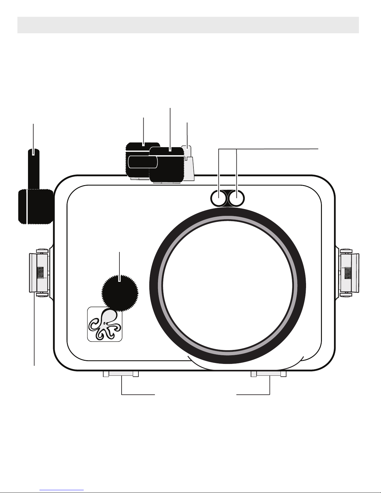
Parts of the Housing - Front View
Housing controls are provided for all camera functions except the
flash up switch and viewfinder switch. The built-in camera flash must be
extended BEFORE placing the camera in the housing.
Shutter
Release
Mode Dial
Control Ring
Zoom Lever
ON/OFF (Power) Button
Fiber
Optic
Ports
Lens Port
Lid Snap
External Tray Mount
Control Ring: To properly engage the Control Ring on the surface or in
shallow water, apply slight downward pressure as you rotate the knob.
Always check to see if the Control Ring teeth are meshing properly with
the Housing Control Gear.
5
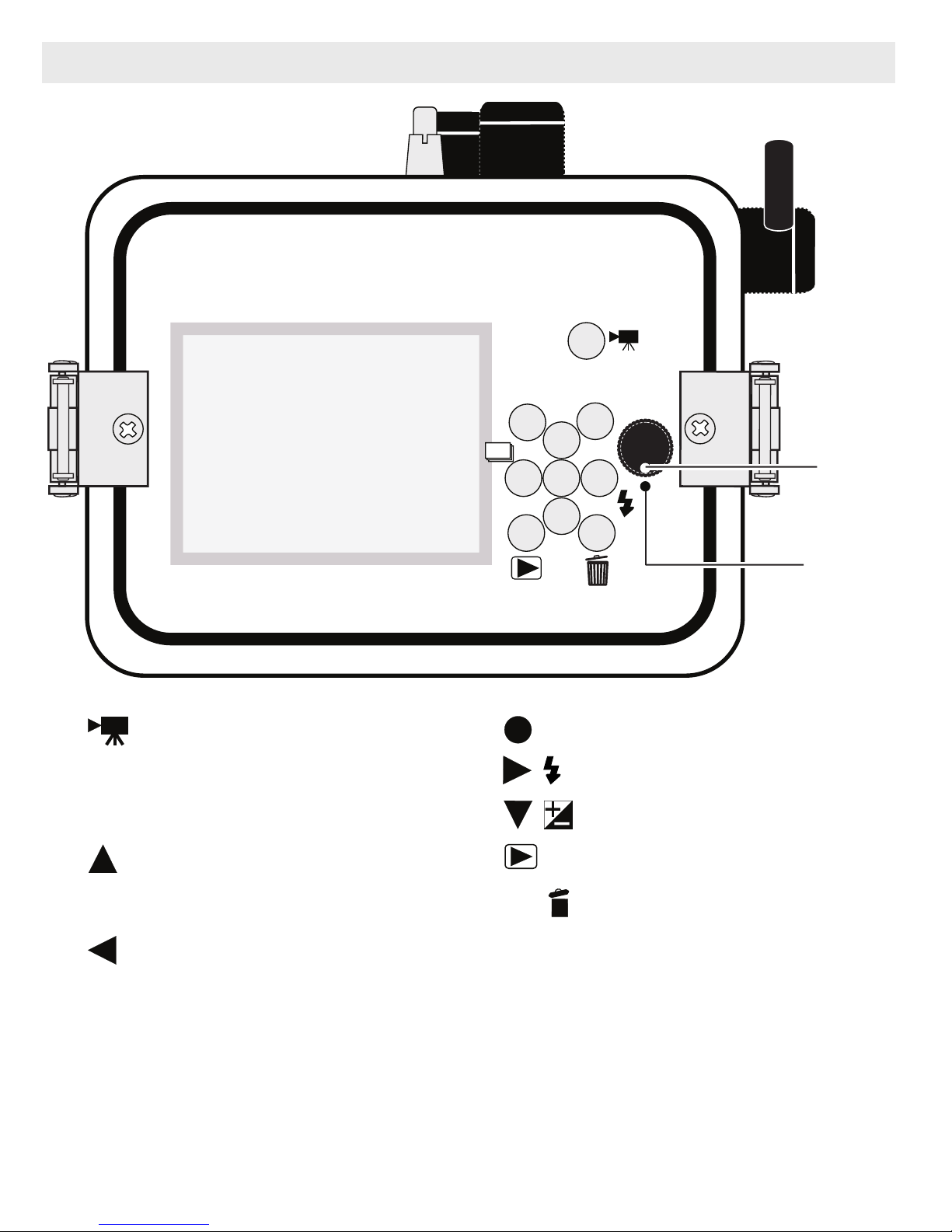
Parts of the Housing - Back View
1
1. MOVIE Button
2. Fn Function Button
3. MENU Button
3
87
MENU
5
Control
Wheel
Dot
Fn
2
4
6
9
10
7. Set / Tracking Focus
8. Flash Mode / Right Button
9. Exp. Comp. / Down Button
11
Housing
Dot
4. DISP Display / UP Button
5. * Control Wheel
6. Drive Mode / Left Button
* Control Wheel: Note that a small section of the rubber disc is missing at the end of this
control. This is normal and allows the user to completely disengage the control from the
camera when not in use. To disengage Control wheel, rotate Control Wheel Knob to the
6 o’clock position, lining up the Knob’s White Dot with the Housing Dot. Rotate Control
Knob White Dot to
12 o’clock position when attaching or removing Housing Back.
10. Playback Button
11. C / Delete Button
6

Housing and Camera Setup
1
STEP 1 - Initial Camera Setup
Setup your camera for underwater use and then adjust your settings once underwater.
- Set Mode Dial to “A” Aperture Priority. Manually adjust aperture setting to
achieve the best exposure for your shooting conditions. The shutter
speed will be locked at 1/30th second. If a faster shutter speed is
desired, set Mode Dial to “M” Manual mode to manually adjust both
aperture and shutter speed settings.
- In MENU settings:
Set Image Size to “L: 20M” and Aspect Ratio to “3:2” or other preffered
setting.
Set Quality to “X.FINE” Extra Fine.”
Set Drive Mode to “Single Shooting” and Red Eye Reduction to “Off.”
(before placing camera in housing)
Set Focus Mode to “Single-shot AF” and Focus Area to “Center.”
Set AF Illuminator to “Off.”
Set ISO to “200” and ND Filter to “Off.”
Set Metering Mode to “Center” and White Balance to “Auto WB.” For
best results and when using a color filter, manually set white balance
for each working depth.
Set DRO/Auto HDR “OFF.”
Set SteadyShot to “On” and Auto Review to “5 Sec.”
Set Pre-AF to “On” and Zoom Setting to “Optical Zoom Only.”
Set Monitor Brightness to “Manual +1.”
Set Pwr Save Start Time to “5 min.”
Set Date and Time.
Insert and Format a memory card.
- Set Flash Mode to “Fill-flash .”
7
STEP 1 - Initial Camera Setup
- continued
If close-up images are overexposed, adjust aperture setting and/or use
“-” Flash Exposure Compensation and/or back away, zoom in, and
then reshoot.
- RAISE the camera flash before placing camera in housing (no housing
control is provided for this function).
** All camera user settings not listed should be set to the user’s
preference.
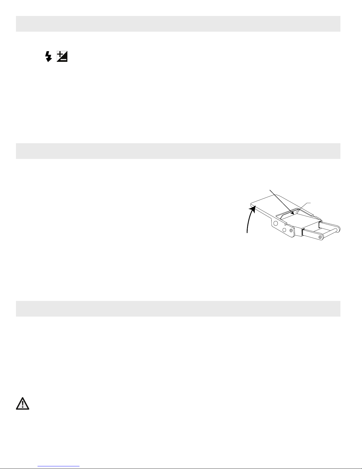
STEP 2 - Opening the Housing
Lid Snaps have a Lock.
1. Push Lid Snap Locks forward and lift as shown.
Push Forward
Open opposing Lid Snaps simultaneously. Keep
pressure on the Lid Snaps so they do not fly
open quickly.
Some Lid Snaps have a lot of spring tension
Lift
once they go over center, so keep a firm grip on
each Lid Snap. Lid Snaps may also be opened
one at a time.
2. Remove the Housing Back.
STEP 3 - Attach Camera to Mounting Tray
1. The Mounting Tray for the camera is secured to the housing back.
Position the camera on the Mounting Tray.
2. Using a coin or screwdriver (preferred), secure the camera with the
Lid
Snap
Lock
Mounting Tray Bolt which threads into the camera’s tripod socket,
Diagram B
, page 9.
CAUTION:
Do not cross thread or overtighten the Mounting Tray Bolt as you may
damage the camera tripod socket threads.
8
SONY
ZEISS
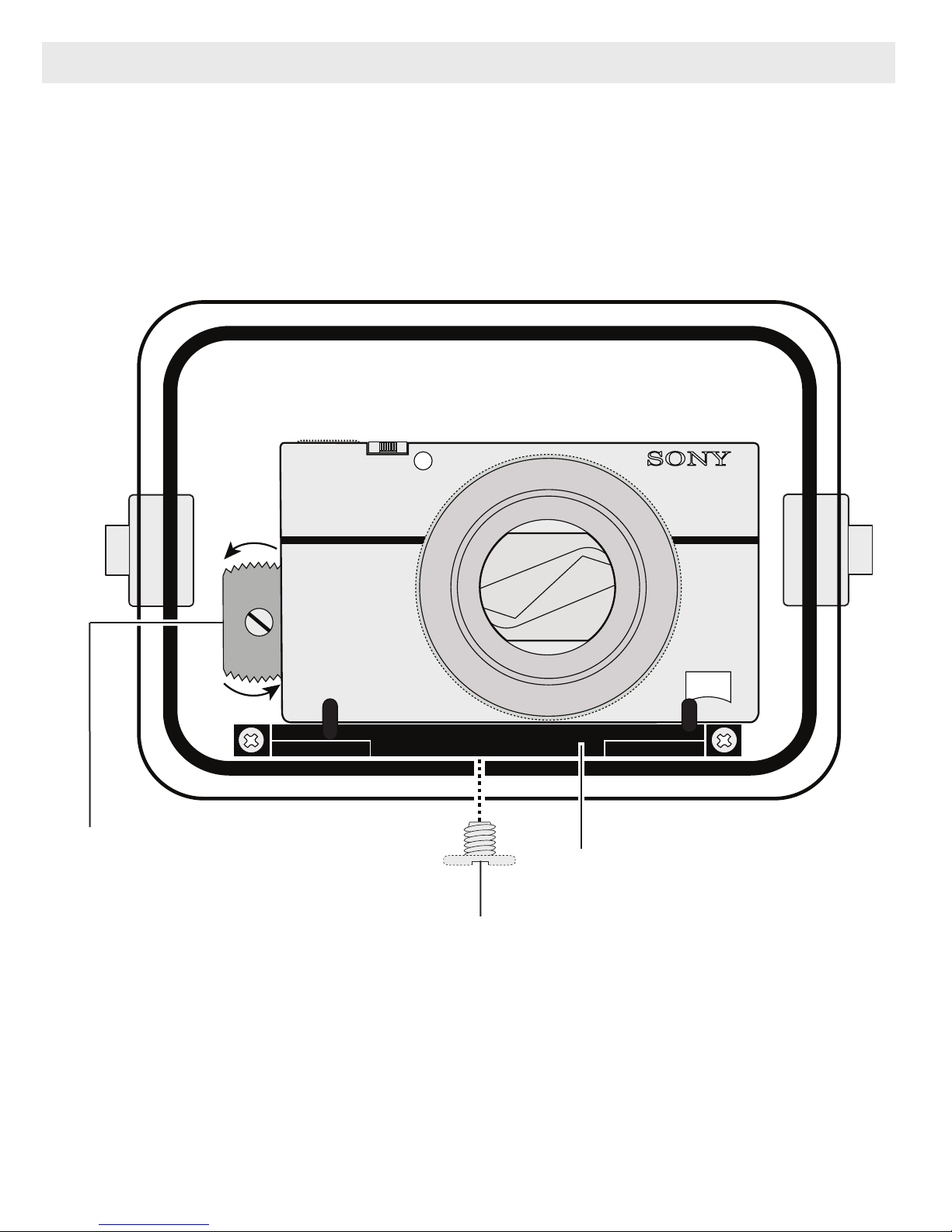
STEP 3 - Attach Camera to Mounting Tray - continued
Diagram B
* Control Wheel “cut away.” When not
in use, rotate Control Wheel knob
white dot to the 6 o’clock position so
“cut away” is over camera dial and
not contacting camera.
Mounting Tray
Mounting Tray Bolt
9
SONY
ZEISS
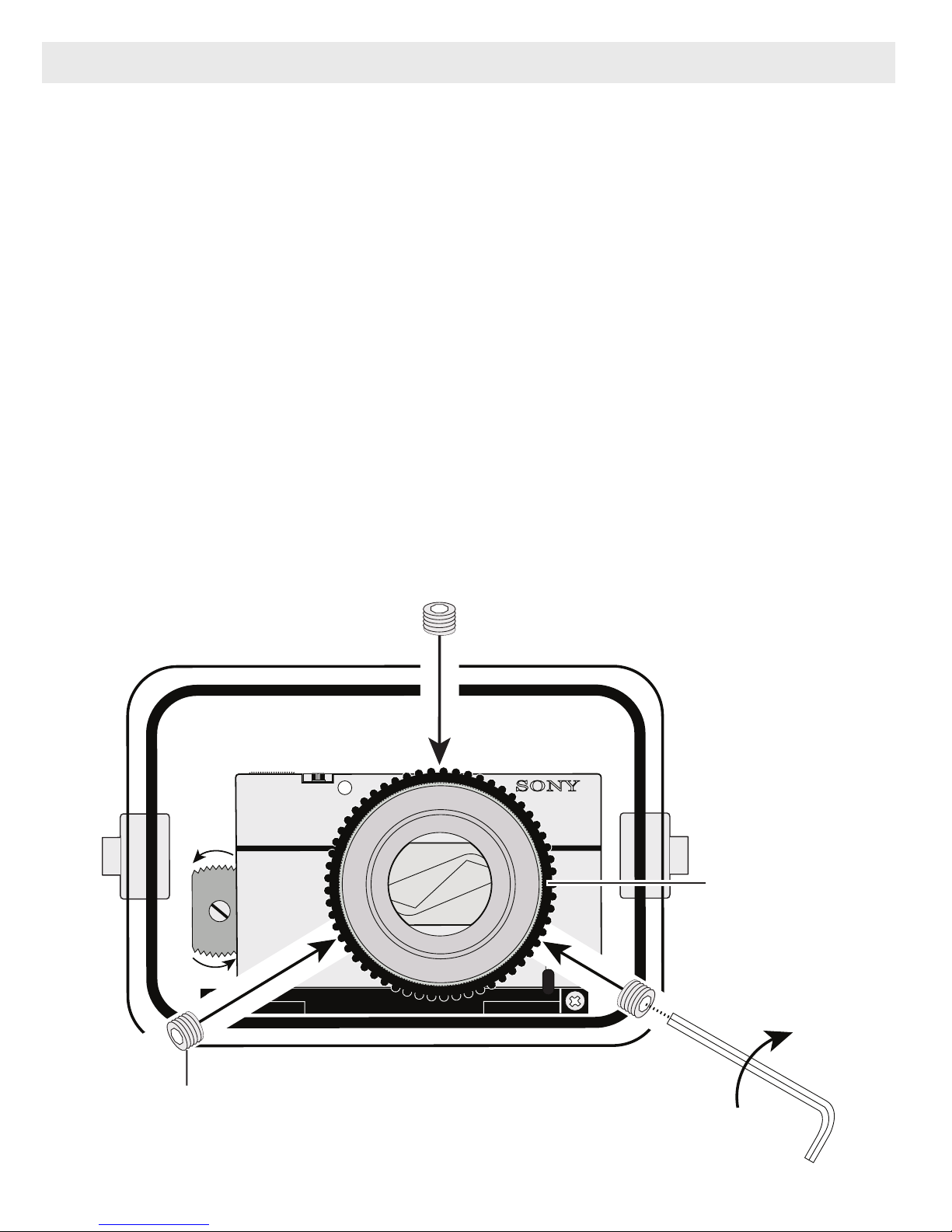
STEP 4 - Attach the Control Ring Gear
The supplied Control Ring Gear is attached to the camera control ring by
3 small nylon Allen Set Screws. Place the Control Ring Gear over the
camera’s step ring before installing the camera in the housing. The Gear
is a “press fit” over the lens. Gently tighten all three allen screws with
the supplied Allen Wrench as show below. DO NOT overtighten or you
may damage the gear, or cause it to warp and bow out from the lens
Control Ring. Make sure to test it’s function once installed.
When installing the camera in the housing, make sure that the Control
Ring Gear meshes properly with the smaller black housing gear.
When removing the Gear, leave the Set Screws in the Gear. The Set
Screws are very small and easy to lose. Extra Set Screws are included
with your housing. We recommend that you leave the Gear installed as
it makes rotating the camera control ring easier when out of the housing.
Control Ring Gear
(properly installed)
Set Screw
10
Turn clockwise to tighten. DO NOT overtighten
or you may warp or damage the gear.
Allen
Wrench
 Loading...