


 Loading...
S Series
Ultrasound System
Service Manual

SonoSite, Inc.
21919 30th Drive SE Bothell, WA 98021-3904 USA
Telephone: 1-888-482-9449 or 1-425-951-1200 Fax: 1-425-951-1201
SonoSite Ltd
Alexander House
40A Wilbury Way
Hitchin, Herts
SG4 OAP UK
T: +44-1462-444800
F: +44-1462-444801
Caution: Federal (United States) law restricts this device to sale by or on the order of a physician.
S Series, SiteLink, SonoCalc, SonoHD, SonoMB, and SonoSite are registered trademarks or trademarks of SonoSite, Inc.
DICOM is the registered trademark of the National Electrical Manufacturers Association for its standards publications relating to digital communications of medical information.
Non-SonoSite product names may be trademarks or registered trademarks of their respective owners.
Protected by U.S. patents: 5722412, 5817024, 5893363, 6135961, 6364839, 6371918, 6383139, 6416475, 6471651, 6569101, 6648826, 6962566, 7169108, D456509, D538432. Patents pending.
P08386-01 3/2008
Copyright 2008 by SonoSite, Inc.
All rights reserved.
ii

Contents |
|
Chapter 1: Introduction |
|
Audience ........................................................................................................................... |
1 |
Conventions .................................................................................................................... |
1 |
Contact Information ..................................................................................................... |
1 |
Chapter 2: System Overview |
|
About the System .......................................................................................................... |
3 |
Theory of Operation ..................................................................................................... |
3 |
System Specifications .................................................................................................. |
6 |
Chapter 3: Troubleshooting |
|
Periodic Maintenance ................................................................................................ |
11 |
Technical Bulletins ....................................................................................................... |
11 |
System and Subsystem Diagnosis ......................................................................... |
11 |
System Repair ............................................................................................................... |
11 |
Test Equipment ............................................................................................................ |
11 |
Failure (Assert) Codes ................................................................................................. |
12 |
Chapter 4: Replacement Procedures |
|
Required Tools .............................................................................................................. |
13 |
Rear Cover Removal .................................................................................................... |
13 |
Rear Cover Installation ............................................................................................... |
14 |
Major System Components ..................................................................................... |
14 |
Superplug Assembly Removal ................................................................................ |
15 |
Superplug Installation ............................................................................................... |
18 |
Power Supply PCBA Replacement ......................................................................... |
19 |
Mini-dock Assembly Replacement ....................................................................... |
20 |
SD Card Daughter-card Replacement .................................................................. |
23 |
Audio I/O PCBA Replacement ................................................................................. |
28 |
USB I/O PCBA Replacement ..................................................................................... |
28 |
Main PCBA Replacement .......................................................................................... |
30 |
Other Major System Components ......................................................................... |
35 |
LCD Replacement ........................................................................................................ |
36 |
Display Backlight Inverter PCBA Replacement ................................................. |
38 |
Control Panel PCBA Replacement ......................................................................... |
39 |
TGC PCBA Replacement ............................................................................................ |
41 |
Chapter 5: Performance Testing |
|
Overview ........................................................................................................................ |
43 |
Test Equipment ............................................................................................................ |
43 |
Set Up Performance Tests ......................................................................................... |
43 |
Basic Operational Tests .............................................................................................. |
43 |
2D Performance Tests ................................................................................................ |
44 |
Additional Performance Tests ................................................................................. |
46 |
Appendix A: Replacement Parts List |
|
Major System Components ..................................................................................... |
49 |
Other System Components ..................................................................................... |
50 |
Miscellaneous System Components ..................................................................... |
51 |
Fan Housing ................................................................................................................... |
52 |
Enclosure Assembly .................................................................................................... |
53 |
Transducer Nest Frame Assembly ......................................................................... |
54 |
iii

Ordering Replacement Parts ................................................................................... |
54 |
Appendix B: Service Event Report |
|
Service Event Report Form ....................................................................................... |
56 |
Service Event Report Instructions ......................................................................... |
57 |
Returning Products to SonoSite ............................................................................. |
58 |
Index ........................................................................................................................ |
59 |
iv

Chapter 1: Introduction
Before servicing the S Series ultrasound system, please read this manual. The information applies only to the SonoSite S Series ultrasound system product manufactured after December 7, 2007.
The ultrasound system has multiple configurations and feature sets. All are described in this service manual but not every option may apply to your system. System features depend on your system configuration, transducer, and exam type.
Refer to the S Series Ultrasound System User Guide for additional information regarding safety, system controls, operation, capabilities, and specifications.
Audience
The intended audience of this manual is properly trained field and in house service personnel.
Conventions
These conventions are used in this service manual:
•A WARNING describes precautions necessary to prevent injury or loss of life.
•A Caution describes precautions necessary to protect the products.
•Numbered steps must be performed in a specific order.
•Bulleted lists present information in list format but do not imply a sequence. Labeling symbols are in the user guide.
Contact Information
Questions and comments are encouraged. SonoSite is interested in your feedback regarding the service manual. If you encounter difficulty with the system, use the information in this manual to help correct the problem. If the problem is not covered here, contact SonoSite Technical Support as follows:
Technical Support (USA, Canada) phone: |
1-877-657-8118 |
Technical Support fax: |
1-425-951-6700 |
Technical Support e-mail: |
service@sonosite.com |
SonoSite Web site: |
www.sonosite.com (Select Resources > Support & |
|
Service) |
International Technical Support: |
Contact your local representative or call (USA) |
|
+425-951-1330 |
European Service Center: |
+44-(0)1462-444-800 |
|
e-mail: uk.service@sonosite.com |
Japan Service Center: |
+81-3-5304-5337 |
|
e-mail: service-jp@sonosite.com |
Chapter 1: Introduction |
1 |

2Chapter 1: Introduction

Chapter 2: System Overview
About the System
The SonoSite S Series high resolution ultrasound system is a portable, software controlled, diagnostic ultrasound system using all digital architecture. The system is used to acquire and display high resolution, real time ultrasound data in 2D, Color Power Doppler (CPD), and color Doppler (Color) or in a combination of these modes.
The system provides measurement capabilities for anatomical structures and fetal biometry that provide information used for clinical diagnostic purposes. System features include cine review, image zoom, labeling, biopsy, measurements and calculations, and image storage, review, printing, recording capabilities.
The system/transducer is capable of exceeding a TI or an MI of 1.0 in certain operating modes or mode combinations. The system displays the current output level in terms of one of two bioeffects indices (“Mechanical Index [MI]” and “Thermal Index [TI]”) in accordance with the AIUM/NEMA Standard for Real Time Display of Thermal and Mechanical Acoustic Output Indices on Diagnostic Ultrasound Equipment.
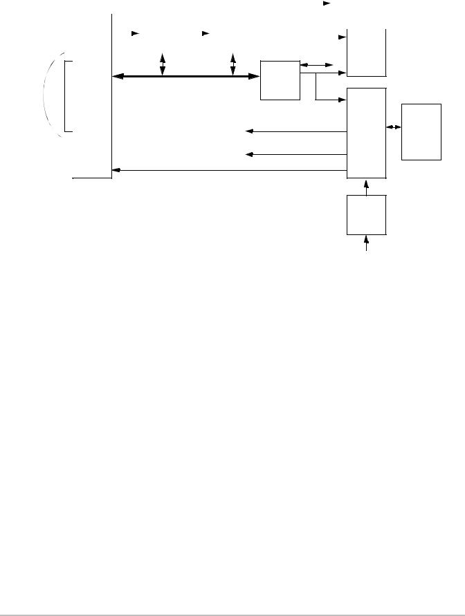
Theory of Operation
The S Series ultrasound system has seven (7) major functional groups:
•Transducer
•Acquisition Subsystem
•Processing Subsystem
•Display Subsystem
•Control Subsystem
•User Interface Subsystem
•Power Subsystem
Figure 2.1 shows the relationship of the functional groups.
Chapter 2: System Overview |
3 |
|
|
|
|
|
|
|
|
|
|
|
External video to |
|||
|
|
RF |
|
|
AQ |
|
|
|
monitor, printer |
|||||
Acquisition |
|
Processing |
|
Display |
|
|
|
|
|
|
||||
|
Bus |
|
Bus |
Video |
|
|
|
|
|
|||||
subsystem |
|
subsystem |
|
subsystem |
|
|
|
|
|
|||||
|
|
|
|
|
|
|
|
|||||||
|
|
|
|
|
|
|
|
|
|
|
|
|
User |
|
|
|
|
|
|
|
|
|
|
|
|
|
|||
|
|
|
|
|
|
|
|
|
|
|
|
|
interface |
|
|
|
IrDA |
|
|
Control |
|
|
Control Bus |
subsystem |
Serial Bus |
|
|
|
Power |
|
|
|
subsystem |
Battery |
|
|
|
|
|
Display power |
pack |
|
|
assembly |
||
|
|
|
|
Transducer
Logic power
Pulser voltage
Power adapter
External power
Figure 2.1 SonoSite High-Resolution Ultrasound System (S Series) Block Diagram
The Transducer elements convert the pulser voltage to acoustic energy during the transmit portion of the ultrasound acquisition cycle. The elements convert the acoustic echo to voltage in the receive portion of the acquisition. The voltage developed on the transducer elements is sensed by the acquisition subsystem. The system transducers have 64 to 192 elements.
The Acquisition Subsystem consists of the beamformer and interface to the transducer. The beamformer controls the timing of the transmit pulses to focus the acoustic beam. The beamformer amplifies the low level received echoes and controls the receive focusing. The system beamformer transmits on up to 128 elements and receives on 64 elements.
The Processing Subsystem includes capabilities for interfacing with the beamformer and performing high speed processing. The processing subsystem demodulates, filters, detects, and compresses the signal supplied by the beamformer into display information.
The Display Subsystem converts the detected ultrasound data into picture elements (pixels). The software user interface graphics are combined with the ultrasound information and converted to a video stream. The external video port supports NTSC and PAL format.
The Control Subsystem consists of the central processing unit, program and video memory, permanent image storage and retrieval memory, external communication interface ports, and connection to the user interface keys. The control software includes the acoustic power and intensity software subsystem, power group monitors, and a beamformer monitor. This software guarantees a level of patient safety by ensuring the system is operating within acoustic power and intensity limits.
The User Interface Subsystem represents the software interface and form factor. The software interface is the interaction between the user and the screen layout components. The form factor is the type of physical buttons, location, and grouping of the buttons and the device size, shape, and weight. Dedicated controls are for high usage activities and grouped according to the user workflow.
4Chapter 2: System Overview

The Power Subsystem provides the system power and protects the hardware from destructive and/or unsafe conditions by detecting failures in the system through hardware and software monitors. Detection of a fault results in disabling of the pulser supply, and signaling of an error to the Control Group. The power subsystem includes the battery pack and battery charging electronics.
Description of Operating Modes
2D Mode |
2D mode is a two dimensional image of the amplitude of the echo signal. It is used for |
|
location and measurement of anatomical structures and for spatial orientation during |
|
operation of other modes. In 2D, a two-dimensional cross-section of a 3-dimensional soft |
|
tissue structure such as the heart is displayed in real time. Ultrasound echoes of different |
|
intensities are mapped to different gray scale or color values in the display. The outline of |
|
the 2D cross-section may be a rectangle, parallelogram, trapezoid, sector, or a full circle, |
|
depending on the particular transducer used. 2D mode can be used in combination with |
|
any other modes. |
Color |
In color Doppler, a real-time, two-dimensional cross-section of blood flow is displayed. The |
Doppler |
2D cross-section may be presented as a rectangle, parallelogram, trapezoid, sector, or a full |
(Color) |
circle, depending on the particular transducer used. |
|
The 2D cross-section is presented as a full color display, with various colors being used to |
|
represent the velocity, both positive and negative, of the blood flow echoes. Often, to |
|
provide spatial orientation, the full color blood flow cross-section is overlaid on top of the |
|
gray scale cross-section of soft tissue structure (2D echo). For each pixel in the overlay, the |
|
decision of whether to display VCD, gray scale (echo) information or a blended combination |
|
is based on the relative strength of echoes from the soft-tissue structures and from the red |
|
blood cells. |
|
A high pass filter (wall filter) is used to remove the signals from stationary or slowly moving |
|
structures. Tissue motion is discriminated from blood flow by assuming that blood is |
|
moving faster than the surrounding tissue, although additional parameters may also be |
|
used to enhance the discrimination. The remaining signal after wall filtering may be |
|
averaged over time (persistence) to present a steady state image of blood flow distribution. |
|
Variance information may also be displayed to provide information when large variance is |
|
observed in the velocity information. |
Color Power |
In CPD, a real-time two-dimensional cross-section of blood flow is displayed. The 2D |
Doppler |
cross-section may be presented as a rectangle, parallelogram, trapezoid, sector, or a full |
(CPD) |
circle, depending on the particular transducer used. |
|
The 2D cross-section is presented as a full color display, with various colors being used to |
|
represent the power in blood flow echoes. Often, to provide spatial orientation, the full color |
|
blood flow cross-section is overlaid on top of the gray scale cross-section of soft tissue |
|
structure (2D echo). For each pixel in the overlay, the decision of whether to display CPD, |
|
gray scale (echo) information or a blended combination is based on the relative strength of |
|
echoes from the soft-tissue structures and from the red blood cells. |
|
A high pass filter (wall filter) is used to remove the signals from stationary or slowly moving |
|
structures. Tissue motion is discriminated from blood flow by assuming that blood is |
|
moving faster than the surrounding tissue, although additional parameters may also be |
|
used to enhance the discrimination. The power in the remaining signal after wall filtering |
|
may be averaged over time (persistence) to present a steady state image of blood flow |
|
distribution. |
Chapter 2: System Overview |
5 |

Additional System Feature Performances
Broadband |
This ultrasound acquisition system uses high resolution broadband technology in the |
Imaging |
transmit pulsers, transducer, and receivers. The receive path can capture and process |
|
signals over a wide spectrum, from below 2.0 MHz to beyond 10 MHz. For each |
|
application, the transmit pulse is designed to produce an appropriate bandwidth. For |
|
example, in 2D grayscale imaging, a wide band pulse is used to support good axial |
|
resolution. For Doppler modes, a narrower band pulse is used, which improves the |
|
spectral resolution of the detected Doppler signal. |
|
In addition to transmit pulse control, programmable digital signal processing is used in |
|
the receive path to further refine the bandwidth used to produce the final image. Digital |
|
filters are applied to the digitized received signal to limit and shape the spectral |
|
bandwidth used to generate the displayed output. |
Biopsy |
The system can display a pair of biopsy guidelines that represent the anticipated path of |
Guidance |
the biopsy needle. The image of an anatomical target, biopsy guidelines, a scan plane |
|
marker, and a biopsy needle are displayed to assist in guiding the biopsy needle to the |
|
target. The system also provides needle guidance for vascular access procedures. For |
|
additional information, see the biopsy user guides. |
Measurement |
The system offers a variety of measurements and calculations, specific to exam type and |
and |
transducer. A list of them, and author references, are in the system user guide. |
Calculation |
Measurement accuracy is also discussed. |
Capabilities |
|
System Specifications
This section contains system and accessory specifications and agency approvals. The specifications for recommended peripherals can be found in the manufacturers’ instructions. See the applicable SonoSite accessory user guide for information on the accessories.
System Dimensions
Height: 15.1 in. (38.4 cm)
Width: 11.6 in. (29.5 cm)
Depth: 6.1 in. (15.5 cm)
Weight: 8.35 lbs. (3.79 kg)
Display Dimensions
Length: 8.4 in. (21.34 cm)
Height: 6.3 in. (16 cm)
Diagonal: 10.4 in. (26.4 cm)
Transducers
Note: Each of the S Series system types (S ICU, S Nerve, etc.) supports a unique combination of transducers.
C11x/5 2 MHz 11 mm curved array (6 ft./1.8 m)
C60x/5 2 MHz 60 mm curved array (5.5 ft./1.7 m)
HFL38x/13 6 MHz 25 mm linear array (5.6 ft./1.7 m)
ICTx/8 5 MHz 11 mm intracavitary array (5.5 ft./1.7 m)
L25x/13 6 MHz 25 mm linear array (7.5 ft./2.3 m)
6Chapter 2: System Overview
L38x/10 5 MHz 38 mm linear array (5.5 ft./1.7 m)
P21x/5 1 MHz 21 mm phased array (6 ft./1.8 m)
Imaging Modes
2D (256 gray shades)
Color power Doppler (CPD) (256 colors)
Color Doppler (Color) (256 colors)
Image and Clip Storage
The number of images and clips you can save varies with imaging mode and file format.
Accessories
Hardware, Software, and Documentation
Battery
Biopsy Guide
Kensington Security Cable
Needle Guides
Power supply
SiteLink Image Manager 4.0
S Series Stand
System User Guide
System AC PowerCcord (10 ft / 3.1 m)
USB Keyboard
VESA Compliant Mounting
Video and printer cables
Cables
See the S Series Ultrasound System User Guide or the S Series Stand User Guide for information on cables.
Peripherals
Peripherals include the following medical grade (conforming to the requirements of EN60601 1) and non medical grade (commercial) products. Manufacturer’s instructions accompany each peripheral. System setup instructions are in the S Series Ultrasound System User Guide. Instructions for using peripherals with the system are in the applicable SonoSite accessory user guide.
Medical Grade
Black and white printer
DVD recorder
Barcode Scanner
Non-Medical Grade
USB Memory Stick
Chapter 2: System Overview |
7 |

Temperature, Pressure, and Humidity Limits
Note: The temperature, pressure, and humidity limits apply only to the ultrasound system and transducers.
Operating Limits: System
•10–40°C (50–104°F), 15–95% R.H.
•700 to 1060hPa (0.7 to 1.05 ATM) Operating Limits: Battery
•10–40°C (50–104°F), 15–95% R.H.
•700 to 1060hPa (0.7 to 1.05 ATM) Operating Limits: Transducer 10–40°C (50–104°F), 15–95% R.H.
Shipping/Storage Limits: System without Battery
•35–65°C ( 31–149°F), 15–95% R.H.
•500 to 1060hPa (0.5 to 1.05 ATM) Shipping/Storage Limits: Battery
•20–60°C ( 4–140°F), 0–95% R.H.*
•500 to 1060hPa (0.5 to 1.05 ATM)
*For storage longer than 30 days, store at or below room temperature.
•10–40°C (50–104°F), 15–95% R.H.
Shipping/Storage Limits: Transducer
• 35–65°C ( 31–149°F), 15–95% R.H.
Electrical
Power Supply Input: |
100 240 VAC, 50/60 Hz, 2.0 A Max @ 100 VAC. |
Power Supply Output 1: |
15 VDC, 5.0A Max (system) |
Power Supply Output 2: |
12 VDC, 2.3A Max (battery) |
Combined output not exceeding 75W.
Battery
6 cell, 11.2 VDC, 5.2 amp hours, rechargeable lithium ion battery pack.
Run time is up to 2 hours, depending on imaging mode and display brightness.
Electromechanical Safety Standards
EN 60601 1:1997, European Norm, Medical Electrical Equipment–Part 1. General Requirements for Safety.
EN 60601 1 1:2001, European Norm, Medical Electrical Equipment–Part 1. General Requirements for Safety–Section 1 1. Collateral Standard. Safety Requirements for Medical Electrical Systems.
EN 60601 1 2:2001, European Norm, Medical Electrical Equipment – Part 1 2: General Requirements for Safety Collateral Standard: Electromagnetic compatibility Requirements and tests
EN 60601-2-37:2001 + Amendment A1:2005, European Norm, Particular requirements for the safety of ultrasonic medical diagnostic and monitoring equipment.
CAN/CSA C22.2, No. 601.1-M 90, Canadian Standards Association, Medical ElectricalEquipment.Part 1. General Requirements for Safety (including CSA 601.1 Supplement 1:1994 and CSA 601.1 Amendment 2:1998)
8Chapter 2: System Overview

CEI/IEC 61157:1992, International Electrotechnical Commission, Requirements for the Declaration of the Acoustic Output of Medical Diagnostic Ultrasonic Equipment.
UL 60601-1 (1st Edition), Underwriters Laboratories, Medical Electrical EquipmentPart 1: General Requirements for Safety.
EMC Standards Classification
EN 60601 1 2:2001, European Norm, Medical Electrical Equipment. General Requirements for Safety Collateral Standard. Electromagnetic Compatibility. Requirements and Tests.
CISPR11:2004, International Electrotechnical Commission, International Special Committee on Radio Interference. Industrial, Scientific, and Medical (ISM) Radio Frequency Equipment Electromagnetic Disturbance Characteristics Limits and Methods of Measurement.
The Classification for the SonoSite system, SiteStand, accessories, and peripherals when configured together is: Group 1, Class A.
Airborne Equipment Standards
RTCA/DO-160E:200 4, Radio Technical Commission for Aeronautics, Environmental Conditions and Test Procedures for Airborne Equipment, Section 21.0 Emission of Radio Frequency Energy, Category B.
DICOM Standard
NEMA PS 3.15: 2000, Digital Imaging and Communications in Medicine (DICOM) Part 15: Security Profiles.
HIPAA Standard
The Health Insurance and Portability and Accountability Act, Pub.L. No. 104 191 (1996).
45 CFR 160, General Administrative Requirements.
45 CFR 164, Security and Privacy.
Chapter 2: System Overview |
9 |

10 Chapter 2: System Overview

Chapter 3: Troubleshooting
This chapter contains information to help you correct problems with system operation and provides instructions on the proper care of the system, transducer, and accessories.
Periodic Maintenance
There is no recommended periodic or preventive maintenance required for the system, transducers, or accessories. There are no internal adjustments or alignments required. There are no functions that require periodic testing or calibration. Performance tests are described in Chapter 5, “Performance Testing,” of this manual. Performing maintenance activities not described in this manual may void the product warranty.
Local regulations may require electrical safety testing.
Contact SonoSite Technical Support for any maintenance questions.
Technical Bulletins
Product Technical Bulletins describing known system issues are periodically placed on SonoSite.com. Select Resources > Support & Service, and then follow the links to S Series support documents.
System and Subsystem Diagnosis
This section covers basic diagnostic and troubleshooting procedures you may follow if the system does not operate properly. To diagnose system failures, consult the referenced diagnostic figures that follow or SonoSite Technical Support.
Table 3.1: Troubleshooting Subassemblies and Diagnostic Figures
Subassemblies |
Diagnostic Figures or Table |
|
|
Display |
TBA |
|
|
Battery |
TBA |
|
|
Control Panel |
TBA |
|
|
System Repair
The system is repairable through subassembly replacement or through replacement of parts as recommended by SonoSite in Chapter 4, “Replacement Procedures.” Component level repair of Printed Circuit Board Assemblies is performed only at the SonoSite repair facility. Replacement of board level components by unauthorized service facilities voids the SonoSite warranty.
Test Equipment
Test equipment is not required for this troubleshooting section. Troubleshooting test aids include an external monitor and a spare battery.
Chapter 3: Troubleshooting |
11 |

Failure (Assert) Codes
ʺAssertʺor ʺAssert Codeʺare software error codes that are generated by all Sonosite products when certain hardware or software fault conditions exist. Providing the Assert Code to the Technical Support Group may assist in quicker and more accurate fault diagnosis.
Hardware Assert Codes typically cannot be reset and will usually require Main PCBA replacement. Many software Assert Codes can be reset and the system may recover and operate normally.
Handling Assert Codes
1Record the Assert Code. The Assert Code is a four or five digit number inside of parentheses on the maintenance screen (Blue screen with screwdriver symbol). See Figure 3.1.
Assert Code
Figure 3.1 Maintenance Screen with Assert Code
2 Press and release the Power button to power the system down.
3Press the Power button again to power the system up.
•If the system powers up normally, it has recovered from the fault (software assert) and you may use the system.
•If the Assert Code remains, corrective action must be taken; usually replacement of the main PCBA is required. Contact SonoSite Technical Support for assistance and to obtain repair parts.
If the Power button is not functional, all sources of power must be removed to allow the system to power down. I.e., disconnect AC power and remove the battery.
12 |
Chapter 3: Troubleshooting |
Chapter 4: Replacement Procedures
Caution: Always use correct ESD procedures. ESD damage is cumulative and may not be noticeable at first. Initial ESD symptoms may be slightly degraded performance or image quality.
Required Tools
•#1 Phillips screwdriver
•#1 Flat Blade screwdriver
•2mm Allen Key
•Torque screwdriver, 2.0–10.0 inch pounds (0.23–1.1 Newton meter)
•Scissors
•Cotton swabs (Q Tips)
•Anti static mat
•Wrist grounding strap
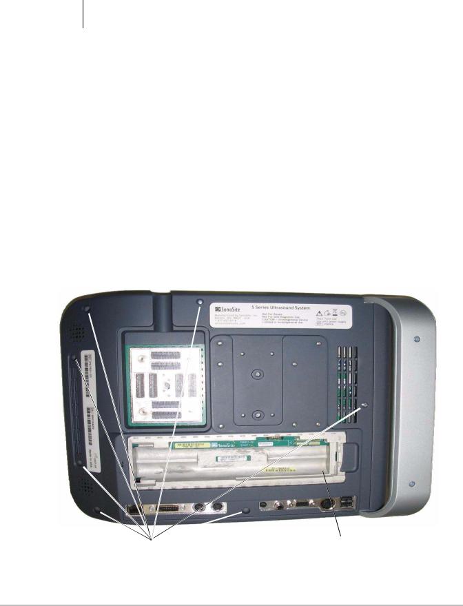
Rear Cover Removal
Removal of the Rear Cover is required to access all other system components.
1 Remove the battery from the system.
2 Remove the seven screws from the Rear Cover as shown in Figure 4.1.
Screws (7x) |
Battery removed |
Figure 4.1 Rear Cover Removal
Chapter 4: Replacement Procedures |
13 |
Rear Cover Installation
1 Insert the top of the Rear Cover under the top cap, and press down to mate with the Front Enclosure.
2 Install the seven screws removed from the Rear Cover and torque to 5.5 inch/pounds.
3 Install the battery.
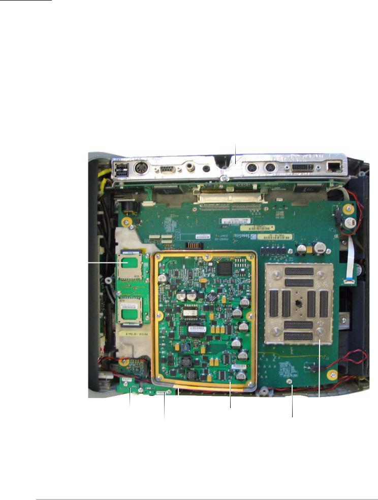
Major System Components
All of the components shown below, including the frame they are mounted on, are called the Superplug Assembly. The Superplug Assembly cannot be ordered but is referenced throughout these instructions. Removal of the Superplug Assembly is required to replace many of the other system components.
Mini-dock Assembly
SD Card Daughter Card (Shown without Copper Tape)
USB I/O PCBA |
|
Power Supply |
|
|
|
|
|
|
|
||
|
|
PCBA |
Main PCBA |
|
|
Audio I/O PCBA |
|
(Shown with Shield |
Nest Frame |
||
|
|
||||
|
|
Removed) |
|
Assembly |
|
|
|
|
|
|
|
Power Supply |
|
|
|
|
|
Frame |
|
|
|
|
|
Figure 4.2 Major System Components
14 Chapter 4: Replacement Procedures
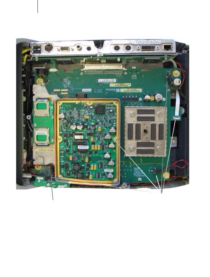
Superplug Assembly Removal
Caution: Improper removal of the cable connectors could damage components on the Main PCBA. Use extreme caution when removing the connectors.
1 Remove the Rear Cover as described in “Rear Cover Removal” on page 13.
2 Disconnect the five cable connectors as shown in Figure 4.3.
Disconnect connectors (5x).
Use extreme caution when removing this connector to prevent damage to the components underneath.
Figure 4.3 Disconnecting Superplug Cables
Chapter 4: Replacement Procedures |
15 |

3 Remove the nine Superplug Assembly mounting screws as shown in Figure 4.4.
Remove 9 Superplug
Assembly screws.
Figure 4.4 Superplug Assembly Screw Removal
16 Chapter 4: Replacement Procedures
Loading...