


 Loading...
M-TurboTM
Ultrasound System
Service Manual

SonoSite, Inc.
21919 30th Drive SE Bothell, WA 98021-3904 USA
Telephone: 1-888-482-9449 or 1-425-951-1200 Fax: 1-425-951-1201
SonoSite Ltd
Alexander House
40A Wilbury Way
Hitchin, Herts
SG4 OAP UK
T: +44-1462-444800
F: +44-1462-444801
Caution: Federal (United States) law restricts this device to sale by or on the order of a physician.
M-Turbo, SiteLink, SonoCalc, SonoHD, SonoMB, and SonoSite are registered trademarks or trademarks of SonoSite, Inc.
DICOM is the registered trademark of the National Electrical Manufacturers Association for its standards publications relating to digital communications of medical information.
Non-SonoSite product names may be trademarks or registered trademarks of their respective owners.
Protected by U.S. patents: 5722412, 5817024, 5893363, 6135961, 6364839, 6371918, 6383139, 6416475, 6471651, 6569101, 6648826, 6962566, 7169108, D456509, D538432. Patents pending.
P08144-01 12/2007
Copyright 2007 by SonoSite, Inc.
All rights reserved.
ii

Contents |
|
Chapter 1: Introduction |
|
Audience ........................................................................................................................... |
1 |
Conventions .................................................................................................................... |
1 |
Contact Information ..................................................................................................... |
1 |
Chapter 2: System Overview |
|
About the System .......................................................................................................... |
3 |
Theory of Operation ..................................................................................................... |
4 |
Description of Operating Modes .................................................................... |
5 |
Additional System Feature Performances ................................................... |
7 |
ECG Module ............................................................................................................ |
8 |
DICOM ...................................................................................................................... |
8 |
IMT ............................................................................................................................. |
8 |
System Specifications .................................................................................................. |
8 |
System Dimensions ............................................................................................. |
9 |
Display Dimensions ............................................................................................. |
9 |
Transducers ............................................................................................................ |
9 |
Imaging Modes ..................................................................................................... |
9 |
Image and Clips Storage .................................................................................... |
9 |
Accessories ............................................................................................................. |
9 |
Peripherals ............................................................................................................ |
10 |
Temperature, Pressure, and Humidity Limits ........................................... |
11 |
Electrical ................................................................................................................ |
11 |
Battery .................................................................................................................... |
11 |
Electromechanical Safety Standards ........................................................... |
12 |
EMC Standards Classification ......................................................................... |
12 |
Airborne Equipment Standards .................................................................... |
12 |
DICOM Standard ................................................................................................. |
12 |
HIPAA Standard ................................................................................................... |
12 |
Chapter 3: Troubleshooting |
|
Periodic Maintenance ................................................................................................ |
13 |
System and Subsystem Diagnosis ......................................................................... |
13 |
System Repair ............................................................................................................... |
13 |
Test Equipment ............................................................................................................ |
13 |
Failure (Assert) Codes ................................................................................................. |
14 |
Verifying a System Assert Code ..................................................................... |
14 |
DICOM .................................................................................................................... |
15 |
Chapter 4: Replacement Procedures |
|
Display Replacement ................................................................................................. |
17 |
Required Parts ..................................................................................................... |
17 |
Required Tools ..................................................................................................... |
17 |
Display Removal ................................................................................................. |
17 |
Display Replacement ........................................................................................ |
20 |
Test the Display ................................................................................................... |
20 |
Control Panel Subassembly Replacement .......................................................... |
21 |
Required Parts ..................................................................................................... |
21 |
Required Tools ..................................................................................................... |
21 |
Control Panel Removal ..................................................................................... |
21 |
Control Panel Replacement ............................................................................ |
21 |
Main System Disassembly for Repair and/or Replacement ......................... |
22 |
Required Parts ..................................................................................................... |
22 |
iii

Required Tools ..................................................................................................... |
22 |
System Disassembly .......................................................................................... |
22 |
Chapter 5: Performance Testing |
|
Overview ........................................................................................................................ |
33 |
Test Equipment ............................................................................................................ |
33 |
Setting Up Performance Tests ................................................................................ |
33 |
Basic Operational Tests .............................................................................................. |
34 |
2D Performance Tests ................................................................................................ |
34 |
2D Performance / Image Quality .................................................................. |
34 |
Axial Measurement Accuracy ........................................................................ |
35 |
Lateral Measurement Accuracy ..................................................................... |
35 |
Penetration ........................................................................................................... |
35 |
Additional Performance Tests ................................................................................. |
36 |
Color Doppler (Color) ........................................................................................ |
36 |
Color Power Doppler (CPD) ............................................................................ |
36 |
M Mode Imaging ................................................................................................ |
37 |
Tissue Harmonic Imaging ................................................................................ |
37 |
Pulsed Wave (PW) Doppler Imaging ........................................................... |
37 |
Continuous Wave (CW) Doppler Imaging ................................................. |
38 |
Image Quality Verification Test/Livescan ................................................... |
38 |
Printer ..................................................................................................................... |
38 |
Battery Charging ................................................................................................ |
39 |
Video Output ....................................................................................................... |
39 |
Appendix A: Replacement Parts List |
|
Display ............................................................................................................................. |
41 |
Control Panel ................................................................................................................. |
42 |
System ............................................................................................................................. |
43 |
Transducer Nest Frame Assembly ......................................................................... |
46 |
Ordering Replacement Parts ................................................................................... |
46 |
Appendix B: Service Event Report |
|
Service Event Report Form ....................................................................................... |
48 |
Service Event Report Instructions ......................................................................... |
49 |
Returning Products to SonoSite ............................................................................. |
50 |
Shipping Instructions ....................................................................................... |
50 |
Index ........................................................................................................................ |
51 |
iv

Chapter 1: Introduction
Before servicing the M-Turbo ultrasound system, please read this manual. The information applies only to the SonoSite M-Turbo ultrasound system product manufactured after December 5, 2007.
The ultrasound system has multiple configurations and feature sets. All are described in this service manual but not every option may apply to your system. System features depend on your system configuration, transducer, and exam type.
Refer to the M-Turbo Ultrasound System User Guide for additional information regarding safety, system controls, operation, capabilities, and specifications.
Audience
The intended audience of this manual is properly trained field and in-house service personnel.
Conventions
These conventions are used in this service manual:
•A WARNING describes precautions necessary to prevent injury or loss of life.
•A Caution describes precautions necessary to protect the products.
•Numbered steps must be performed in a specific order.
•Bulleted lists present information in list format but do not imply a sequence.
Labeling symbols are in the user guide.
Contact Information
Questions and comments are encouraged. SonoSite is interested in your feedback regarding the service manual. If you encounter difficulty with the system, use the information in this manual to help correct the problem. If the problem is not covered here, contact SonoSite Technical Support as follows:
Technical Support (USA, Canada) |
1-877-657-8118 |
Technical Support fax: |
1-425-951-6700 |
Technical Support e-mail: |
service@sonosite.com |
SonoSite website: |
www.sonosite.com (Select Resources > Support & Service) |
International Technical Support: |
Contact your local representative or call (USA) +425-951-1330 |
European Service Center |
+44-(0)1462-444-800 |
|
e-mail: uk.service@sonosite.com |
Japan Service Center |
+81-3-5304-5337 |
Chapter 1: Introduction |
1 |

2Chapter 1: Introduction

Chapter 2: System Overview
About the System
The SonoSite M-Turbo high-resolution ultrasound system is a portable, full featured, general purpose, software controlled, diagnostic ultrasound system using all digital architecture. The system is used to acquire and display high-resolution, real-time ultrasound data in 2D, M Mode, Pulsed Wave (PW) Doppler, Continuous Wave (CW)
Doppler, Color Power Doppler (CPD), and color Doppler (Color) or in a combination of these modes.
The system has an electrocardiography (ECG) display feature and supports a 3-lead ECG cable assembly to collect data for M Mode and Doppler measurements. The system provides measurement capabilities for anatomical structures and fetal biometry that provide information used for clinical diagnostic purposes. The system has a PW and CW Doppler audio output feature and cine review, image zoom, labeling, biopsy, measurements and calculations, image storage and review, printing, and recording capabilities.
The system includes the ability to measure the intima-media thickness (IMT) of the carotid artery using digital ultrasound images. The IMT measurement of the carotid artery may be used adjunctively with other medical data obtained by a physician to help assess the cardiovascular health of a patient.
The system includes Digital Imaging and Communications (DICOM) capabilities as well as general computer communication capabilities to provide the acceptance, transfer, display, storage, and digital processing of ultrasound images and loops. Security support is also provided to facilitate HIPAA compliance.
The system/transducer is capable of exceeding a TI or an MI of 1.0 in certain operating modes or mode combinations. The system displays the current output level in terms of one of two bioeffects indices (“Mechanical Index [MI]” and “Thermal Index [TI]”) in accordance with the AIUM/NEMA Standard for Real Time Display of Thermal and Mechanical Acoustic Output Indices on Diagnostic Ultrasound Equipment.
Chapter 2: System Overview |
3 |

Theory of Operation
The M-Turbo ultrasound system has seven (7) major functional groups:
•Transducer
•Acquisition Subsystem
•Processing Subsystem
•Display Subsystem
•Control Subsystem
•User Interface Subsystem
•Power Subsystem
Figure 2.1 is a system block diagram that shows the relationship of the functional groups.
 External video to monitor,, printer
Acquisition |
RF Bus |
Processing |
AQ Bus |
Display |
||
subsystem |
|
|
subsystem |
|
|
subsystem Video |
|
|
|
|
|||
|
|
User |
|
IrDA |
interface |
|
|
|
|
Control |
|
Control Bus |
subsystem |
Serial Bus |
|
||
|
|
Power |
|
|
subsystem |
|
|
Battery |
|
Display power |
pack |
|
assembly |
|
|
|
Transducer
Logic power
Pulser voltage
Power adapter
External power
Figure 2.1 SonoSite High-Resolution Ultrasound System (M-Turbo) Block Diagram
The Transducer elements convert the pulser voltage to acoustic energy during the transmit portion of the ultrasound acquisition cycle. The elements convert the acoustic echo to voltage in the receive portion of the acquisition. The voltage developed on the transducer elements is sensed by the acquisition subsystem. The system transducers have 64 to 192 elements.
The Acquisition Subsystem consists of the beamformer and interface to the transducer. The beamformer controls the timing of the transmit pulses to focus the acoustic beam. The beamformer amplifies the low-level received echos and controls the receive focusing. The system beamformer transmits on up to 128 elements and receives on 64 elements.
The Processing Subsystem includes capabilities for interfacing with the beamformer and performing high speed processing. The processing subsystem demodulates, filters, detects, and compresses the signal supplied by the beamformer into display information.
4 |
Chapter 2: System Overview |

The Display Subsystem converts the detected ultrasound data into picture elements (pixels). The software user interface graphics are combined with the ultrasound information and converted to a video stream. The external video port supports NTSC and PAL format.
The Control Subsystem consists of the central processing unit, program and video memory, permanent image storage and retrieval memory, external communication interface ports, and connection to the user interface keys. The control software includes the acoustic power and intensity software subsystem, power group monitors, and a beamformer monitor. This software guarantees a level of patient safety by ensuring the system is operating within acoustic power and intensity limits.
The User Interface Subsystem represents the software interface and form factor. The software interface is the interaction between the user and the screen layout components. The form factor is the type of physical buttons, location, and grouping of the buttons and the device size, shape, and weight. Dedicated controls are for high usage activities and grouped according to the user workflow.
The Power Subsystem provides the system power and protects the hardware from destructive and/or unsafe conditions by detecting failures in the system through hardware and software monitors. Detection of a fault results in disabling of the pulser supply, and signaling of an error to the Control Group. The power subsystem includes the battery pack and battery charging electronics.
Description of Operating Modes
2D Mode |
2D mode is a two dimensional image of the amplitude of the echo signal. It is used for |
|
location and measurement of anatomical structures and for spatial orientation during |
|
operation of other modes. In 2D, a two-dimensional cross-section of a 3-dimensional soft |
|
tissue structure such as the heart is displayed in real time. Ultrasound echoes of different |
|
intensities are mapped to different gray scale or color values in the display. The outline of the |
|
2D cross-section may be a rectangle, parallelogram, trapezoid, sector, or a full circle, |
|
depending on the particular transducer used. 2D mode can be used in combination with any |
|
other modes. |
M Mode |
M Mode is also known as “T-M mode” or “time-motion” mode. It is used primarily for cardiac |
|
measurements such as valve timing and septal wall thickness when accurate timing |
|
information is required. |
|
Ultrasound echoes of different intensities are mapped to different gray scale values in a |
|
scrolling display. M Mode displays time motion information of the ultrasound data derived |
|
from a stationary beam. Depth is arranged along the vertical axis with time along the |
|
horizontal axis. M Mode can be used alone but is normally used in conjunction with a 2D |
|
image for spatial reference. The 2D image has a graphical line (M-line) superimposed on the |
|
2D image indicating where the M Mode beam is located. |
Chapter 2: System Overview |
5 |

Color |
In color Doppler, a real-time, two-dimensional cross-section of blood flow is displayed. The |
Doppler |
2D cross-section may be presented as a rectangle, parallelogram, trapezoid, sector, or a full |
(Color) |
circle, depending on the particular transducer used. |
|
The 2D cross-section is presented as a full color display, with various colors being used to |
|
represent the velocity, both positive and negative, of the blood flow echoes. Often, to |
|
provide spatial orientation, the full color blood flow cross-section is overlaid on top of the |
|
gray scale cross-section of soft tissue structure (2D echo). For each pixel in the overlay, the |
|
decision of whether to display VCD, gray scale (echo) information or a blended combination |
|
is based on the relative strength of echoes from the soft-tissue structures and from the red |
|
blood cells. |
|
A high pass filter (wall filter) is used to remove the signals from stationary or slowly moving |
|
structures. Tissue motion is discriminated from blood flow by assuming that blood is moving |
|
faster than the surrounding tissue, although additional parameters may also be used to |
|
enhance the discrimination. The remaining signal after wall filtering may be averaged over |
|
time (persistence) to present a steady state image of blood flow distribution. Variance |
|
information may also be displayed to provide information when large variance is observed in |
|
the velocity information. |
Color Power |
In CPD, a real-time two-dimensional cross-section of blood flow is displayed. The 2D |
Doppler |
cross-section may be presented as a rectangle, parallelogram, trapezoid, sector, or a full |
(CPD) |
circle, depending on the particular transducer used. |
|
The 2D cross-section is presented as a full color display, with various colors being used to |
|
represent the power in blood flow echoes. Often, to provide spatial orientation, the full color |
|
blood flow cross-section is overlaid on top of the gray scale cross-section of soft tissue |
|
structure (2D echo). For each pixel in the overlay, the decision of whether to display CPD, gray |
|
scale (echo) information or a blended combination is based on the relative strength of |
|
echoes from the soft-tissue structures and from the red blood cells. |
|
A high pass filter (wall filter) is used to remove the signals from stationary or slowly moving |
|
structures. Tissue motion is discriminated from blood flow by assuming that blood is moving |
|
faster than the surrounding tissue, although additional parameters may also be used to |
|
enhance the discrimination. The power in the remaining signal after wall filtering may be |
|
averaged over time (persistence) to present a steady state image of blood flow distribution. |
Continuous |
CW provides a real-time representation of blood flow and is displayed as a |
Wave (CW) |
velocity-versus-time sweeping output. Velocity (or frequency) is presented as the vertical |
Doppler |
axis with time along the horizontal axis. The magnitude of the detected signal is represented |
|
as different gray scale values. |
|
CW Doppler mode provides the clinician with the ability to obtain blood flow velocities |
|
focused about a user specified focal region. A continuous transmit waveform of ultrasound |
|
energy with a known frequency is transmitted and focused by the system; on the receive |
|
side, the transducer receive echoes are continuously amplified, focused about the focal |
|
region and converted to a base band quadrature signal. The signal is analyzed by a |
|
quadrature phase detector that establishes two receive channels to allow detection of flow |
|
direction. These two channels are then analyzed by a fast complex Fourier transform (FFT) |
|
circuit to establish the spectrum of frequencies present in the echoes. The data are displayed |
|
as spectrum frequencies with respect to time. |
|
CW can be used alone but is normally used in conjunction with a 2D image for spatial |
|
reference. The 2D image has a graphical line (D-line) superimposed on the 2D image |
|
indicating where the M-mode beam is located. |
6 |
Chapter 2: System Overview |
Pulsed Wave PW provides a real-time representation of blood flow and is displayed as a
(PW) Doppler velocity-versus-time sweeping output. Velocity (or frequency) is presented as the vertical axis with time along the horizontal axis. The magnitude of the detected signal is represented as different gray scale values. The ultrasound data is derived from a single area, the sample volume, on a stationary beam.
PW Doppler mode provides the clinician with the ability to obtain blood flow velocities about a spatial sample volume. A burst of ultrasound with a known spectrum is transmitted by the system; on the receive side, the transducer receive echoes are amplified and range gated at the appropriate depth. The signal is analyzed by a quadrature phase detector that establishes two receive channels to allow detection of flow direction. These two channels are then analyzed by a fast complex Fourier transform (FFT) circuit to establish the spectrum of frequencies present in the echoes. The data are displayed as spectrum frequencies with respect to time.
PW can be used alone but is normally used in conjunction with a 2D image for spatial reference. The 2D image has a graphical line (D-line) superimposed on the 2D image indicating where the M-mode beam is located. The sample volume position (depth) and size are also indicated on the D-Line.
Additional System Feature Performances
Broadband Imaging |
This ultrasound acquisition system uses high resolution broadband technology in |
|
the transmit pulsers, transducer, and receivers. The receive path can capture and |
|
process signals over a wide spectrum, from below 2.0 MHz to beyond 10 MHz. For |
|
each application, the transmit pulse is designed to produce an appropriate |
|
bandwidth. For example, in 2D grayscale imaging, a wide band pulse is used to |
|
support good axial resolution. For Doppler modes, a narrower band pulse is used, |
|
which improves the spectral resolution of the detected Doppler signal. |
|
In addition to transmit pulse control, programmable digital signal processing is used |
|
in the receive path to further refine the bandwidth used to produce the final image. |
|
Digital filters are applied to the digitized received signal to limit and shape the |
|
spectral bandwidth used to generate the displayed output. |
Tissue Specific |
In this feature, parameters for signal and image processing are optimized to |
Imaging |
maximize the image quality or to obtain the best compromise of resolution and |
|
penetration for different specific clinical applications. These parameters include: the |
|
order of received filters, the bandwidth, the dynamic range, the compression curve, |
|
the gain setting and parameters for compounding frequency band, etc. For |
|
example, different system parameter setups are used for abdominal or peritoneal |
|
scanning. This feature is for ease of use for the operator by automatically setting up |
|
system control parameters rather than manually adjusting settings for best |
|
performance. |
Biopsy Guidance |
The system can display a pair of biopsy guidelines that represent the anticipated |
|
path of the biopsy needle. The image of an anatomical target, biopsy guidelines, a |
|
scan plane marker, and a biopsy needle are displayed to assist in guiding the biopsy |
|
needle to the target. The system also provides needle guidance for vascular access |
|
procedures. For additional information, see the biopsy user guides. |
Measurement and |
The system offers a variety of measurements and calculations, specific to exam type |
Calculation |
and transducer. A list of them , and author references, are in the system user guide. |
Capabilities |
Measurement accuracy is also discussed. |
Chapter 2: System Overview |
7 |

Continuous Wave |
The system provides for audio output of the CW velocity information. This can be |
Doppler Audio |
presented as stereo information, with flow moving towards the transducer on one |
Output |
channel and flow away on the other, or as a mono output with the single audio |
|
output representing the summation of the flow directions. |
Pulsed Wave Doppler |
The system provides for audio output of the PW velocity information. This can be |
Audio Output |
presented as stereo information, with flow moving towards the transducer on one |
|
channel and flow away on the other, or as a mono output with the single audio |
|
output representing the summation of the flow directions. |
Electrocardiograph |
ECG is provided to measure the electrical signal generated by the heart. A three lead |
(ECG) Display |
interface: Right Arm (RA), Left Arm (LA) and Left Leg (LL), is provided on the system. |
|
The ECG signal is displayed as an amplitude-versus-time sweeping output. |
|
Amplitude is presented on the vertical axis with time along the horizontal axis. |
ECG Module
The ECG module allows a representation of the heart electrical activity to be displayed in real time with ultrasound images acquired and displayed on the system video display.
The ECG module interfaces to the patient through three (3) ECG leads: Right Arm ECG lead (RA), Left Arm ECG lead (LA), and Left Leg ECG lead (LL). The ECG received signal from the ECG electrodes are isolated, amplified, and filtered by the ECG module before it is sent to the system for further processing and display.
The ECG module and cable are an integrated assembly. The module receives power from the system. Patient isolation is provided by the ECG module, allowing the connection and signals to the system to be system-ground referenced. The isolation between the patient and the system meets the requirements of IEC 601-1 for Type BF equipment.
DICOM
The system features Digital Imaging and Communications (DICOM) capability to provide the acceptance, transfer, display, storage, and digital processing of single ultrasound images as well as loops of ultrasound images.
IMT
The system includes the ability to measure the intima-media thickness (IMT) of the carotid artery using digital ultrasound images. The intima is that region of the arterial wall from and including the endothelial surface at the lumen to the luminal margin of the media. The media layer extends from the intima to the adventitia of the vessel wall. The adventitia is normally quite echogenic on ultrasound images when compared to the media. The IMT measurement of the carotid artery may be used adjunctively with other medical data obtained by a physician to help assess the cardiovascular health of a patient.
System Specifications
This section contains system and accessory specifications and agency approvals. The specifications for recommended peripherals can be found in the manufacturers’ instructions. See the applicable SonoSite accessory user guide for information on the accessories.
8 |
Chapter 2: System Overview |

System Dimensions
Length: 11.8 in. (29.97 cm)
Width: 10.8 in. (27.43 cm)
Height: 3.1 in. (7.87 cm)
Weight: 8.5 lbs. (3.9 kg) with the C60x transducer and battery installed
Display Dimensions
Length: 8.4 in. (21.34 cm)
Height: 6.3 in. (16 cm)
Diagonal: 10.4 in. (26.4 cm)
Transducers
C11x/5-2 MHz 11 mm curved array (6 ft./1.8 m)
C60x/5-2 MHz 60 mm curved array (5.5 ft./1.7 m)
HFL38x/13-6 MHz 25 mm linear array (5.6 ft./1.7 m)
ICTx/8-5 MHz 11 mm intracavitary array (5.5 ft./1.7 m)
L25x/13-6 MHz 25 mm linear array (7.5 ft./2.3 m)
L38x/10-5 MHz 38 mm linear array (5.5 ft./1.7 m)
P21x/5-1 MHz 21 mm phased array (6 ft./1.8 m)
Imaging Modes
2D (256 gray shades)
Color power Doppler (CPD) (256 colors)
Color Doppler (Color) (256 colors)
Continuous Wave (CW) Doppler
M Mode
Pulsed wave (PW) Doppler
Tissue Doppler Imaging (TDI)
Tissue Harmonic Imaging (THI)
Image and Clips Storage
The number of images and clips you can save varies with imaging mode and file format.
Accessories
Hardware, Software, and Documentation
Barcode Scanner
Battery
Biopsy Guide
Carry case
Chapter 2: System Overview |
9 |

ECG Cable (6 ft/1.8m)
External display
Footswitch
Kensington Security Cable
Mini-Dock
Mobile Docking System Lite II (MDS Lite II)
Mobile Docking System M Series (MDSm)
Needle Guide
Power supply
Quick Reference Guide
SiteLink Image Manager 4.0
SonoCalc IMT
System User Guide
System AC PowerCcord (10 ft / 3.1 m)
Triple Transducer Connect
Video and printer cables
Cables
See the M-Turbo Ultrasound System User Guide, MDSm User Guide, and the MDS Lite II User Guide for information on cables.
Peripherals
Peripherals include the following medical grade (conforming to the requirements of EN60601-1) and non-medical grade (commercial) products. Manufacturer’s instructions accompany each peripheral. System setup instructions are in the M-Turbo Ultrasound System User Guide. Instructions for using peripherals with the system are in the applicable SonoSite accessory user guide.
Medical Grade
Black-and-white printer
Recommended sources for printer paper: Contact CIVCO at 1-800-445-6741 or www.civco.com to order supplies or to find the local distributor.
Color printer
DVD recorder
15” External monitor
Non-Medical Grade
USB Memory Stick
10 Chapter 2: System Overview

Temperature, Pressure, and Humidity Limits
Note: The temperature, pressure, and humidity limits apply only to the ultrasound system and transducers.
Operating Limits: System
•10–40°C (50–104°F), 15–95% R.H.
•700 to 1060hPa (0.7 to 1.05 ATM)
Operating Limits: Battery
•10–40°C (50–104°F), 15–95% R.H.
•700 to 1060hPa (0.7 to 1.05 ATM)
Operating Limits: Transducer
10–40°C (50–104°F), 15–95% R.H.
Shipping/Storage Limits: System without Battery
•-35–65°C (-31–149°F), 15–95% R.H.
•500 to 1060hPa (0.5 to 1.05 ATM)
Shipping/Storage Limits: Battery
•-20–60°C (-4–140°F), 0–95% R.H.*
•500 to 1060hPa (0.5 to 1.05 ATM)
* For storage longer than 30 days, store at or below room temperature.
•10–40°C (50–104°F), 15–95% R.H. Shipping/Storage Limits: Transducer
•-35–65°C (-31–149°F), 15–95% R.H.
Electrical
Power Supply Input: |
100-240 VAC, 50/60 Hz, 2.0 A Max @ 100 VAC. |
|
Power Supply Output 1 |
15 VDC, |
5.0A Max (system) |
Power Supply Output 2 |
12 VDC, |
2.3A Max (battery) |
Combined output not exceeding 75W. |
|
|
Battery
6-cell, 11.2 VDC, 5.2 amp-hours, rechargeable lithium ion battery pack.
Run time is up to 2 hours, depending on imaging mode and display brightness.
Chapter 2: System Overview |
11 |

Electromechanical Safety Standards
EN 60601-1:1997, European Norm, Medical Electrical Equipment–Part 1. General Requirements for Safety.
EN 60601-1-1:2001, European Norm, Medical Electrical Equipment–Part 1. General Requirements for Safety–Section 1-1. Collateral Standard. Safety Requirements for Medical Electrical Systems.
EN 60601]2]37:2001 + Amendment A1:2005, European Norm, Particular requirements for the safety of ultrasonic medical diagnostic and monitoring equipment.
CAN/CSA C22.2, No. 601.1]M90, Canadian Standards Association, Medical ElectricalEquipment.Part 1. General Requirements for Safety (including CSA 601.1 Supplement 1:1994 and CSA 601.1 Amendment 2:1998)
.CEI/IEC 61157:1992, International Electrotechnical Commission, Requirements for the Declaration of the Acoustic Output of Medical Diagnostic Ultrasonic Equipment.
UL 60601]1 (1st Edition), Underwriters Laboratories, Medical Electrical Equipment] Part 1: General Requirements for Safety.
EMC Standards Classification
EN 60601-1-2:2001, European Norm, Medical Electrical Equipment. General Requirements for Safety-Collateral Standard. Electromagnetic Compatibility. Requirements and Tests.
CISPR11:2004, International Electrotechnical Commission, International Special Committee on Radio Interference. Industrial, Scientific, and Medical (ISM) Radio-Frequency Equipment Electromagnetic Disturbance Characteristics-Limits and Methods of Measurement.
The Classification for the SonoSite system, SiteStand, accessories, and peripherals when configured together is: Group 1, Class A.
Airborne Equipment Standards
RTCA/DO]160E:2004, Radio Technical Commission for Aeronautics, Environmental Conditions and Test Procedures for Airborne Equipment, Section 21.0 Emission of Radio Frequency Energy, Category B.
DICOM Standard
NEMA PS 3.15: 2000, Digital Imaging and Communications in Medicine (DICOM)-Part 15: Security Profiles.
HIPAA Standard
The Health Insurance and Portability and Accountability Act, Pub.L. No. 104-191 (1996).
45 CFR 160, General Administrative Requirements.
45 CFR 164, Security and Privacy.
12 Chapter 2: System Overview

Chapter 3: Troubleshooting
This chapter contains information to help you correct problems with system operation and provides instructions on the proper care of the system, transducer, and accessories.
Periodic Maintenance
There is no recommended periodic or preventive maintenance required for the system, transducers, or accessories. There are no internal adjustments or alignments required. There are no functions that require periodic testing or calibration. Performance tests are described in Chapter 5, “Performance Testing” of this manual. Performing maintenance activities not described in this manual may void the product warranty.
Local regulations may require electrical safety testing.
Contact SonoSite Technical Support for any maintenance questions.
System and Subsystem Diagnosis
This section covers basic diagnostic and troubleshooting procedures you may follow if the system does not operate properly. To diagnose system failures, consult the referenced diagnostic figures that follow or SonoSite Technical Support.
Table 3.1: Troubleshooting Subassemblies and Diagnostic Figures
Subassemblies |
Diagnostic Figures or Table |
|
|
DICOM |
Table 3.2 |
|
|
Dipslay |
TBA |
|
|
Battery |
TBA |
|
|
Control Panel |
TBA |
|
|
System Repair
The system is repairable through subassembly replacement or through replacement of parts as recommended by SonoSite in Chapter 4, “Replacement Procedures.” Component level repair of Printed Circuit Board Assemblies is performed only at the SonoSite repair facility. Replacement of board level components by unauthorized service facilities voids the SonoSite warranty.
Test Equipment
Test equipment is not required for this troubleshooting section. Troubleshooting test aids include an external monitor and a spare battery.
Chapter 3: Troubleshooting |
13 |
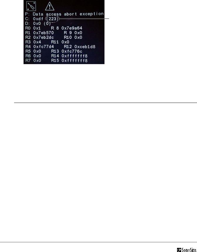
Failure (Assert) Codes
The system displays an “assert screen” for hardware and software issues related to main PCBA failures. Main PCBA failures typically result in “assert codes” that are output to the display. If an assert screen appears, note the assert code and contact SonoSite Technical Support to clarify the failure. Figure 3.1 shows an assert screen. The assert code is the bracketed number on the line labeled “C:”.
Assert code
Figure 3.1 Assert Screen
Verifying a System Assert Code
System asserts are caused by hardware and/or software faults. Hardware asserts typically require main PCBA replacement. Software asserts can be reset and the system may recover. A simple method to identify the cause of the assert is identified here:
Assert Cause 1 Record the assert code.
2Press and release the Power button to power the system down.
3Press the Power button again to power on the system.
•If the system powers on normally, it has recovered from the fault (software assert) and you may use the system.
•If the assert condition remains, corrective action must be taken; usually replacement of the main PCBA is required. Contact SonoSite Technical Support for assistance and to obtain repair parts.
If the Power button is not functional, all sources of power must be removed to allow the system to power down. I.e., disconnect AC power and remove the battery.
14 |
Chapter 3: Troubleshooting |
Loading...