

Page 1
PowerPack
Housing
Nut plates (2)
& Allen-head
screws (2)
Battery &
Phillips-head
screws (2)
T-h and le d
hex
wrench
Phillips screw
driver
Assembly
Assembly Instructions
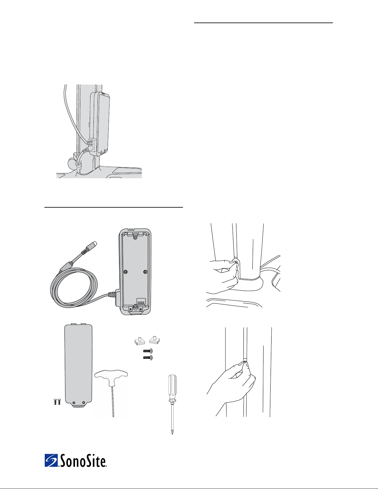
The PowerPack installs on either the H-Universal™ or
V-Universal™ stand.
Figure 1 Installed PowerPack (vertical
installation on back of stand)
Contents
1 Determine orientation and placement.
1 Determine the optimal orientation for installing
the PowerPack (See Figure 4):
• Ver tical orientation is recommended and
helps protect the PowerPack from possible
impact.
• Horizontal orientation is acceptable if other
accessories are present, providing insufficient
space for vertical installation.
2 Determine which side of the column on which to
install the PowerPack: front or back.
Back installation may help protect the PowerPack,
but consider issues such as cord placement (See
Figure 7) and available space on the column.
2 Insert nut plates on stand.
1 Insert a nut plate into the groove at the lower back
(or lower front, for front installation) of the stand
column, and slide it a few inches up the column.
See Figure 2 and Figure 3.
The flat, rubber side of the plate faces toward the
column.
Figure 2 Insert nut plate
.
Figure 3 Slide nut plate up the column.
2 Insert the second nut plate, and slide it up the
column.
3 Space the nut plates so that they align with the
two holes on the housing. (See Figure 4.)
1
Page 2
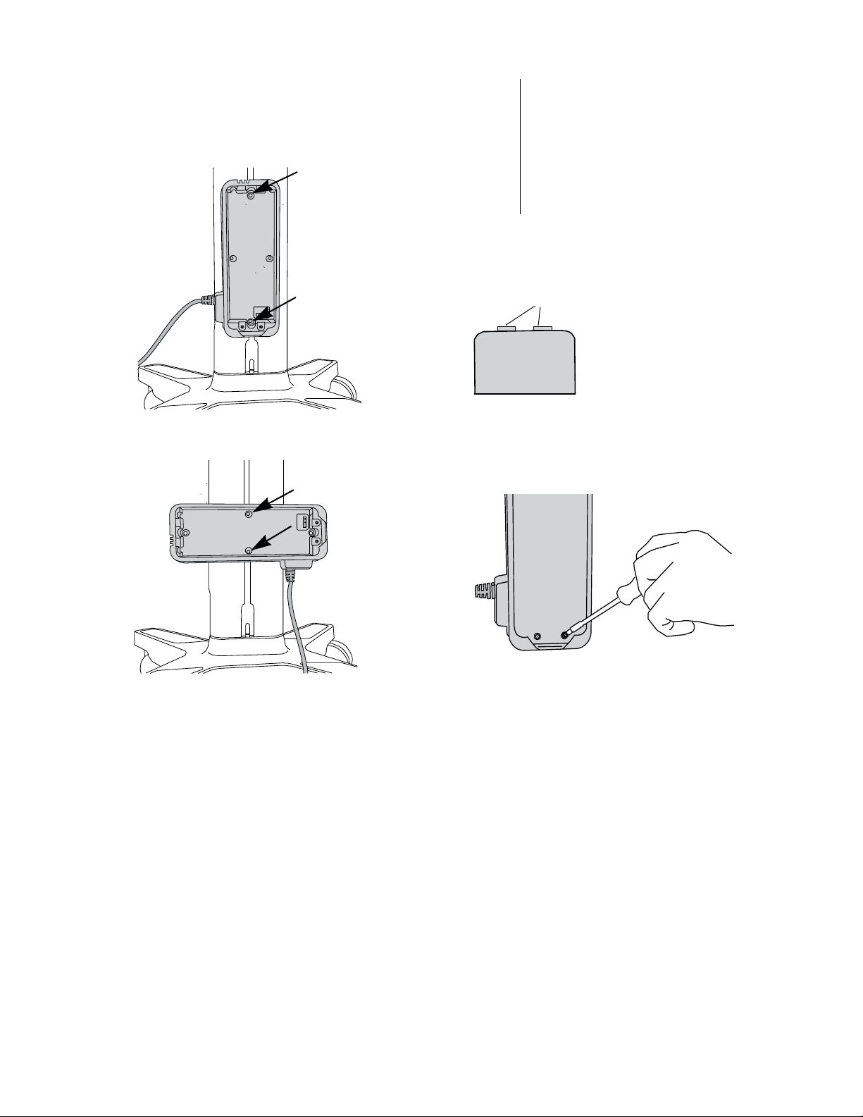
3 Attach housing to stand.
tabs
1 Place the housing against the stand, inserting the
nut plates into the two holes on the housing. (See
Figure 4.)
2 Secure the housing: Using the hex wrench, tighten
an Allen-head screw in each of the two nut plates.
4 Insert the battery.
WAR NIN G:
1 Slide the tabs on the battery into the slots on the
housing, and then press the opposite end of the
battery into place.
Figure 5 Tabs on battery
2 Insert the two Phillips-head screws into the
mounting holes at the base of the battery and
tighten using the Phillips screwdriver.
To avoid injury to the operator and to
prevent damage to the ultrasound
system, inspect the battery for leaks
prior to installing.
To avoid the risk of electrical shock,
do not touch the battery contacts on
the PowerPack battery or housing.
Figure 4 Tighten the 2 screws: Vertical
installation (top) and horizontal installation
(bottom)
Figure 6 Tighten 2 screws on battery
5 Connect cables.
1 Connect the following cables:
• Power supply DC power cord (A) from the
stand to the PowerPack. (See “Cables and
connectors” on page 3.)
• PowerPack DC power cord (Z) to the system
directly, to the NanoMaxx dock, or to the minidock.
2 If charging the battery, connect to AC power:
Connect the system AC power cord (K) to the
stand and a wall outlet. For more information, see
the PowerPack user guide.
2
Page 3

WAR NIN G:
PowerPack DC
power cord (Z)
Power-supply DC
power cord (A)
To system
or dock
To avoid the risk of electrical
shock:
• Use only properly grounded
equipment. Shock hazards
exist if the power supply is not
properly grounded. Grounding
reliability can be achieved only
when equipment is connected
to a receptacle marked
“Hospital Only” or “Hospital
Grade” or the equivalent. The
grounding wire must not be
removed or defeated.
• Use only accessories and
peripherals recommended by
SonoSite, including the power
supply. Use the PowerPack
only with SonoSite power
supply P09823.
• Do not disassemble or alter the
battery.
To avoid the risk of electrical
shock or injury, do not open the
battery enclosure on the
PowerPack battery pack.
To avoid the risk of a shock
hazard, do not plug the stand’s
power cord into a multiple
portable socket outlet (MPSO) or
use an extension cord.
Figure 7 Connect cables A and Z
Cables and connectors
Cable
[Letter]
[Name]
[Illustration]
A
Power-supply
DC power cord
6.8 ft./2 m
Connector 1
[Illustration]
[Connects to]
PowerPack DC
input port
Connector 2
[Illustration]
[Connects to]
Pre-installed
on stand
Caution:
To avoid possible electrical shock
or electromagnetic interference,
verify proper operation and
compliance with relevant safety
standards for all equipment
before clinical use. Connecting
additional equipment to the
ultrasound system constitutes
configuring a medical system.
SonoSite recommends verifying
that the system, all combinations
of equipment, and accessories
connected to the ultrasound
system comply with JACHO
installation requirements and/or
safety standards AAMI-ES1, NFPA
99, IEC 60601-1-1, and IEC 606011-2, and are certified according
to IEC 60950 (Information
Technology Equipment (ITE)).
To prevent the battery from
draining, do not connect the
PowerPack DC power cord to its
own—or another
PowerPack’s—DC input port.
K
System AC
power cord
10 ft./3 m
Z
PowerPack DC
power cord
Stand
Pre-installed
on PowerPack
Wall outlet
DC input on
mini-dock,
NanoMaxx
dock, or system
3
Page 4

Technical Support
SonoSite Technical Support
Phone
(US or Canada):
Phone
(Outside US and
Canada):
Fax: 425-951-6700
E-mail: service@sonosite.com
Web site: www.sonosite.com
Europe Service Center
Phone: +44-(0)1462-444-800
E-mail: uk.service@sonosite.com
877-657-8118
425-951-1330
Or call your local
representative.
H-Universal, SonoSite, V-Universal, and the SonoSite logo are trademarks or registered trademarks of SonoSite, Inc.
Non-SonoSite product names may be trademarks or registered trademarks of their respective owners.
Patents pending.
Caution:
SonoSite, Inc.
21919 30th Drive SE
Bothell, WA 98021 USA
T: 1-888-482-9449 or
1-425-951-1200
F: 1-425-951-1201
P13537-01
Federal (United States) law restricts this device to
sale by or on the order of a physician.
SonoSite Ltd
Alexander House
40A Wilbury Way
Hitchin, Herts
SG4 OAP UK
T: +44-1462-444800
F: +44-1462-444801
07/2010
Copyright 2010 by
SonoSite, Inc.
All rights reserved.
*P13537-01*
4
c
 Loading...