

Page 1
MicroMaxx
®
Ultrasound System
User Guide
Page 2

Page 3

MicroMaxx
Ultrasound System
User Guide
Page 4

SonoSite, Inc.
21919 30th Drive SE
Bothell, WA 98021
USA
T: 1-888-482-9449 or 1-425-951-1200
F: 1-425-951-1201
SonoSite Ltd
Alexander House
40A Wilbury Way
Hitchin
Herts SG4 0AP
UK
T: +44-1462-444800
F: +44-1462-444801
Caution:
Federal (United States) law restricts this device to sale by or on the order of a
physician.
MicroMaxx, SiteLink, SonoCalc, SonoMB, SonoRES, and SonoSite are registered trademarks or trademarks of SonoSite, Inc.
CompactFlash is a registered trademark of Symbol Technologies.
DICOM is the registered trademark of the National Electrical Manufacturers Association for its standards publications relating to digital
communications of medical information.
Non-SonoSite product names may be trademarks or registered trademarks of their respective owners.
The SonoSite product(s) referenced in this document may be covered by one or more of the following patents: 5722412, 5817024,
5893363, 6135961, 6203498, 6364839, 6371918, 6383139, 6416475, 6447451, 6471651, 6569101, 6648826, 6575908, 6604630, 6817982,
6835177, 6962566, 7169108, D456509, D4618 95, D509900, D538432, D544962, D558351, D559390. Patents pending. Other international
patents may also apply.
P06435-07 07/2008
Copyright 2008 by SonoSite, Inc.
All rights reserved.
ii
Page 5

Contents
Introduction 1
About the User Guide 1
Intended Uses 1
Conventions 4
Symbols and Terms 4
Upgrades and User Guide Updates 4
Customer Comments 4
Contact Information 5
About the System 6
About the System Software 8
Getting Started 9
Healthy Scanning Guidelines 9
System Preparation 11
Installing or Removing Battery 11
Installing or Removing CompactFlash Card 12
Using AC Power/Charging Battery 13
Turning System On/Off 14
Connecting or Removing Transducer 15
System Controls 16
Screen Layout 19
General Interaction 20
Touchpad 20
On-Screen Menus 21
Menu Controls 21
Annotation and Text 22
Forms 23
System Setup 24
Set Security Settings 25
Audio and Battery 31
Cardiac Calculations 32
Connectivity 33
Date and Time 35
Delta Key and Annotation 36
Display Information 38
IMT Calculations 39
OB Calculations Authors 40
OB Custom Measurements 42
OB Custom Tables 43
Presets 45
System Information 47
Network Status 48
iii
Page 6

Imaging 49
Patient Information 49
Transducer, Exam Type, and Imaging Mode 52
Transducer Preparation 55
General Use 56
Invasive or Surgical Use 56
Modes 57
2D Imaging 57
M Mode Imaging 61
Color Doppler Imaging 63
Pulsed Wave (PW) and Continuous Wave (CW) Doppler Imaging 65
Clips 68
Clip Acquisition Delay 69
Image and Clip Storage 70
Save to CompactFlash 70
Print to Local Printer 72
Image and Clip Review 72
Patient List 72
Patient Images and Clips 73
Annotations 74
ECG Monitoring 76
Footswitch 77
Bar Code Scanner 78
Needle Guidance 78
Measurements and Calculations 79
Measurements 79
2D Measurements 79
M Mode Measurements 83
Doppler Measurements 85
Calculations 89
Percent Reduction Calculations 90
Volume Calculation 92
Volume Flow Calculation 94
Small Parts Calculations 96
Gyn Calculations 97
OB Calculations 100
Vascular Calculations 108
IMT Calculations 110
Transcranial Doppler Calculations (TCD) 114
Cardiac Calculations 117
Patient Report 135
Connectivity and Configuration 141
System Connectivity Setup 141
iv
Page 7

System Configuration for SiteLink 141
Configuring SiteLink for Ethernet 142
Configuring SiteLink for Wireless 143
System Configuration for DICOM 147
Creating Backup for DICOM Settings 147
Configuring Locations 148
Configuring Archivers 154
Configuring Printers 157
Configuring Worklist Servers 161
Configuring Procedures 164
Importing and Exporting Configurations 165
Reviewing the Network Log 166
DICOM Usage 167
DICOM Image Archive and Print 169
Patient Information 171
DICOM Worklists 172
Troubleshooting and Maintenance 175
Troubleshooting 175
Software Licensing 177
Upgrading the System and Transducer Software 177
Upgrading Triple Transducer Connect (TTC) 183
Obtaining a License Key 184
Installing a License Key 185
Maintenance 186
Recommended Disinfectant 186
Safety 186
Cleaning and Disinfecting Ultrasound System 187
Cleaning and Disinfecting Transducers 188
Sterilizing Transducers 190
Cleaning and Disinfecting Transducer Cables 190
Cleaning and Disinfecting Battery 192
Cleaning Footswitch 192
Cleaning and Disinfecting ECG Cables 192
References 201
Display Size 201
Caliper Placement 201
2D Measurements 201
Sources of Measurement Errors 203
Acquisition Error 203
Algorithmic Error 203
Terminology and Measurement Publications 203
Cardiac References 204
Obstetrical References 210
Gestational Age Tables 211
v
Page 8

Growth Analysis Tables 214
Ratio Calculations 215
General References 216
Specifications 219
System Dimensions 219
Display Dimensions 219
Transducers 219
Imaging Modes 220
Image Storage 220
Accessories 220
Hardware, Software, and Documentation 220
Cables 221
Peripherals 221
Temperature and Humidity Limits 221
Electrical 222
Battery 222
Electromechanical Safety Standards 222
EMC Standards Classification 223
Airborne Equipment Standards 223
DICOM Standard 223
HIPAA Standard 223
Safety 225
Ergonomic Safety 225
Electrical Safety Classification 225
Electrical Safety 226
Equipment Safety 228
Battery Safety 228
Biological Safety 230
Electromagnetic Compatibility (EMC) 230
Manufacturer’s Declaration 232
The ALARA Principle 235
Applying ALARA 235
Direct Controls 236
Indirect Controls 236
Receiver Controls 236
Acoustic Artifacts 236
Guidelines for Reducing MI and TI 237
Output Display 239
Mechanical and Thermal Indices Output Display Accuracy 240
Factors that Contribute to Display Uncertainty 240
Related Guidance Documents 241
Transducer Surface Temperature Rise 242
Acoustic Output Measurement 243
In Situ, Derated, and Water Value Intensities 243
vi
Page 9

Tissue Models and Equipment Survey 244
About the Acoustic Output Table 245
Acoustic Output Tables 246
Acoustic Measurement Precision and Uncertainty 283
Labeling Symbols 283
Glossary 287
Terms 287
Acronyms 289
vii
Page 10

viii
Page 11

Chapter 1: Introduction
Please read the information in this user guide before using the SonoSite® MicroMaxx® ultrasound
system. It applies to the ultrasound system and transducers.
About the User Guide
The MicroMaxx Ultrasound System User Guide provides information on preparing and using the
ultrasound system, on upgrading the system and transducers, and on cleaning and disinfecting the
system and transducers. It also provides references for calculations, system specifications, and
additional safety and acoustic output information.
The MicroMaxx Quick Start Cards, located in the back of the user guide, provide an overview of basic
system functions.
The user guide is designed for a reader familiar with ultrasound techniques; it does not provide
training in sonography or clinical practices. Before using the system, you must have ultrasound
training.
See the applicable SonoSite accessory user guide for information on using accessories and
peripherals. See the manufacturers’ instructions for specific information about peripherals.
Intended Uses
The intended uses for each exam type are contained here. See the intended transducer for exam type
in Table 2, “Transducer, Exam Type, and Imaging Mode” on page 53.
Introduction
Abdominal Imaging Applications
This system transmits ultrasound energy into the abdomen of patients using 2D, M Mode, color
Doppler (Color), color power Doppler (CPD), Tissue Harmonic Imaging (THI), and pulsed wave (PW)
Doppler to obtain ultrasound images. The liver, kidneys, pancreas, spleen, gallbladder, bile ducts,
transplanted organs, abdominal vessels, and surrounding anatomical structures can be assessed for
the presence or absence of pathology transabdominally.
Cardiac Imaging Applications
This system transmits ultrasound energy into the thorax of patients using 2D, M Mode, color Doppler
(Color), Tissue Harmonic Imaging (THI), pulsed wave (PW) Doppler, pulsed wave tissue Doppler (TDI
PW), and continuous wave (CW) Doppler to obtain ultrasound images. The heart, cardiac valves, great
vessels, surrounding anatomical structures, overall cardiac performance, and heart size can be
assessed for the presence or absence of pathology.
The patient’s electrocardiogram (ECG) may be obtained and is used for timing of diastolic and systolic
function.
WAR NIN G:
The ECG is not used to diagnose cardiac arrhythmias and is not designed for long term
cardiac rhythm monitoring.
Chapter 1: Introduction 1
Page 12

Gynecology and Infertility Imaging Applications
This system transmits ultrasound energy in the pelvis and lower abdomen using 2D, M Mode, color
power Doppler (CPD), color Doppler (Color), Tissue Harmonic Imaging (THI), and pulsed wave (PW)
Doppler to obtain ultrasound images. The uterus, ovaries, adnexa, and surrounding anatomical
structures can be assessed for the presence or absence of pathology transabdominally or
transvaginally.
Interventional and Intraoperative Imaging Applications
This system transmits ultrasound energy into the various parts of the body using 2D, color Doppler
(Color), color power Doppler (CPD), Tissue Harmonic Imaging (THI), and pulsed wave (PW) Doppler to
obtain ultrasound images that provide guidance during interventional and intraoperative
procedures. This system can be used to provide ultrasound guidance for biopsy and drainage
procedures, vascular line placement, peripheral nerve blocks, spinal nerve blocks and taps, ova
harvesting, amniocentesis and other obstetrical procedures, and provide assistance during
abdominal, breast, neurological surgery, and vascular intraoperative procedures.
Obstetrical Imaging Applications
This system transmits ultrasound energy into the pelvis of pregnant women using 2D, M Mode, color
Doppler (Color), color power Doppler (CPD), Tissue Harmonic Imaging (THI), and pulsed wave (PW)
Doppler to obtain ultrasound images. The fetal anatomy, viability, estimated fetal weight, gestational
age, amniotic fluid, and surrounding anatomical structures can be assessed for the presence or
absence of pathology transabdominally or transvaginally. CPD and color Doppler (Color) imaging is
intended for high-risk pregnant women. High-risk pregnancy indications include, but are not limited
to, multiple pregnancy, fetal hydrops, placental abnormalities, as well as maternal hypertension,
diabetes, and lupus.
WAR NIN G:
2 Chapter 1: Introduction
To prevent injury or misdiagnosis do not use this system for Percutaneous Umbilical
Blood Sampling (PUBS) or in vitro Fertilization (IVF) The system has not been
validated to be proven effective for these two uses.
CPD or Color images can be used as an adjunctive method, not as a screening tool,
for the detection of structural anomalies of the fetal heart and as an adjunctive
method, not as a screening tool for the diagnosis of Intrauterine Growth Retardation
(IUGR).
Page 13

Pediatric Imaging Applications
This system transmits ultrasound energy into the pediatric patients using 2D, M Mode, color Doppler
(Color), color power Doppler (CPD), pulsed wave (PW) Doppler, pulsed wave tissue Doppler (TDI PW),
and continuous wave (CW) Doppler to obtain ultrasound images. The pediatric abdominal, pelvic and
cardiac anatomy, pediatric hips, neonatal head, and surrounding anatomical structures can be
assessed for the presence or absence of pathology.
Prostate Imaging Applications
This system transmits ultrasound energy into the prostate of an adult male using 2D, M Mode, color
power Doppler (CPD), color Doppler (Color), and pulsed wave (PW) Doppler to obtain ultrasound
images. The prostate gland can be assessed for the presence or absence of pathology.
Superficial Imaging Applications
This system transmits ultrasound energy into various parts of the body using 2D, M Mode, color
Doppler (Color), color power Doppler (CPD), and pulsed wave (PW) Doppler to obtain ultrasound
images. The breast, thyroid, testicle, lymph nodes, hernias, musculoskeletal structures, soft tissue
structures, and surrounding anatomical structures can be assessed for the presence or absence of
pathology. This system can be used to provide ultrasound guidance for biopsy and drainage
procedures, vascular line placement, peripheral nerve blocks, and spinal nerve blocks and taps.
Transcranial Imaging Applications
This system transmits ultrasound energy into the cranium using 2D, color Doppler (Color), color
power Doppler (CPD), and pulsed wave (PW) Doppler to obtain ultrasound images. The anatomical
structures and vascular anatomy of the brain can be assessed for presence or absence of pathology.
Two exam types support transcranial imaging: TCD and Orb. Imaging can be used temporally,
trans-occipitally, or trans-orbitally.
Introduction
WAR NIN G:
To avoid injury to the patient, use only an orbital exam type (Orb) when performing
imaging through the eye. The FDA has established lower acoustic energy limits for
opthalmic use. The system will not exceed these limits only if the Orb exam type is
selected.
Vascular Imaging Applications
This system transmits ultrasound energy into the various parts of the body using 2D, M Mode, color
Doppler (Color), color power Doppler (CPD), and pulsed wave (PW) Doppler to obtain ultrasound
images. The carotid arteries, deep veins, and arteries in the arms and legs, superficial veins in the arms
and legs, great vessels in the abdomen, and various small vessels feeding organs can be assessed for
the presence or absence of pathology.
Chapter 1: Introduction 3
Page 14

Conventions
These conventions are used in this user guide:
•A WAR NIN G describes precautions necessary to prevent injury or loss of life.
•A Caution describes precautions necessary to protect the products.
• Numbered steps in the procedures must be performed in a specific order.
• Bulleted lists present information in list format but do not imply a sequence.
• The system handle is on the front of th e system , and the battery c ompar tment is on t he back of th e
system.
Symbols and Terms
Symbols and terms used on the system and transducer are explained in Chapter 2, “Getting Started”;
Chapter 5, “Connectivity and Configuration”; “Glossary” on page 287; and Chapter 9, “Safety.”
Upgrades and User Guide Updates
SonoSite may offer software upgrades, new features, and improvements to the system performance.
User guide updates accompany the upgrade software and provide detailed information on the
enhancements.
Customer Comments
Questions and comments are encouraged. SonoSite is interested in your feedback regarding the
system and the user guide. Please call SonoSite at 1-888-482-9449. If you are outside the USA, call
the nearest SonoSite representative. You can also e-mail SonoSite at comments@sonosite.com.
4 Chapter 1: Introduction
Page 15

Contact Information
For SonoSite technical support, contact us at the following numbers or addresses:
Technical Support (USA, Canada): 1-877-657-8118
Technical Support fax: 1-425-951-6700
Technical Support e-mail: service@sonosite.com
SonoSite website: www.sonosite.com and select Support
International Technical Support: Contact your local representative or call
Europe Service Center: +44-(0)1462-444-800
Introduction
(USA) +425-951-1330
e-mail: uk.service@sonosite.com
Chapter 1: Introduction 5
Page 16
About the System
4
3
2
1
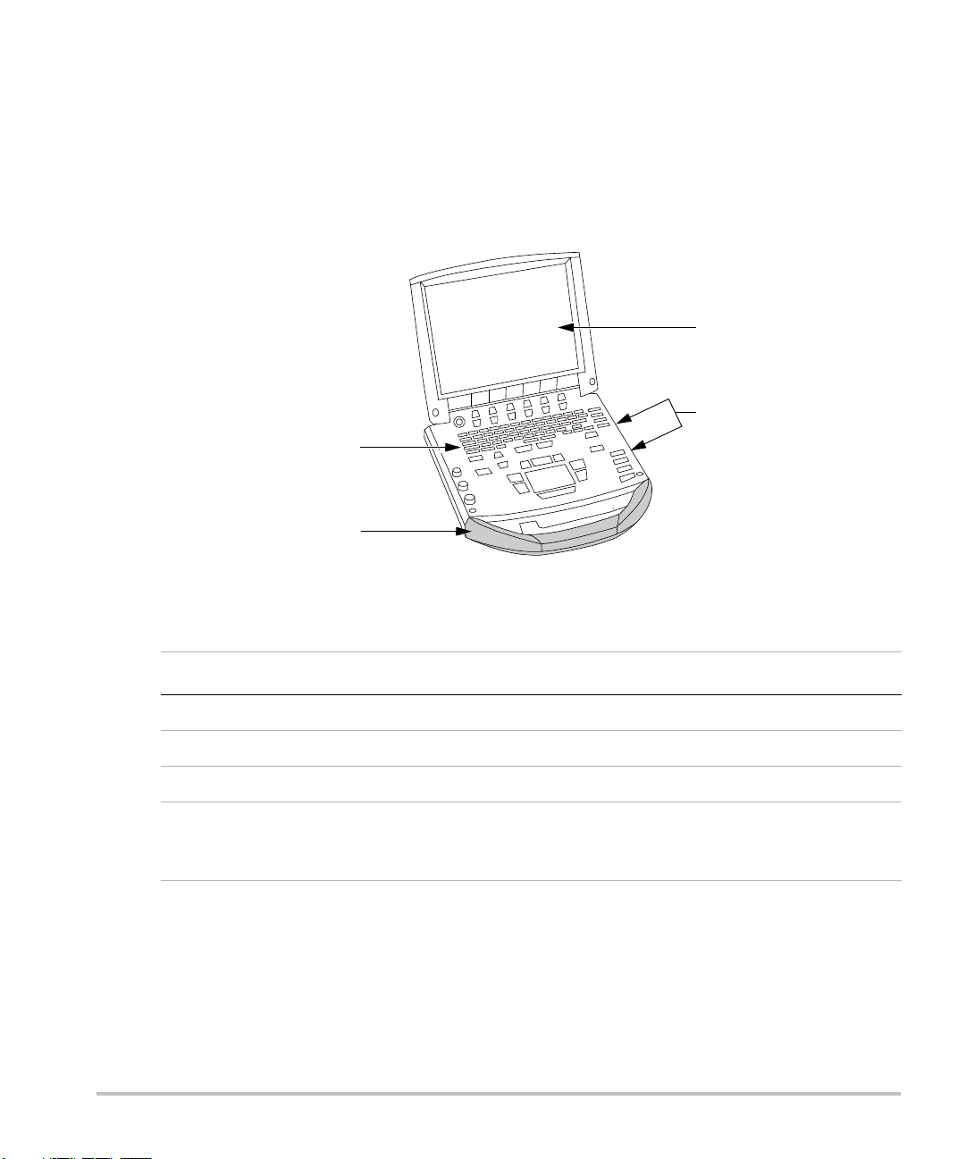
The ultrasound system is a portable, software-controlled, ultrasound system using all-digital
architecture. The system has multiple configurations and feature sets used to acquire and display
high-resolution, real-time ultrasound images. All are described in this user guide but not every option
may apply to your system. Features are dependent on system configuration, transducer, and exam
type.
Figure 1 System Front View
Table 1: System Front Features
Number Feature
1 Control panel
2Handle
3Display
4 CompactFlash® slots: front for image storage, back for system and transducer
updates, import/export OB tables, custom annotations, and user names/passwords,
and Digital Imaging and Communications in Medicine (DICOM®) configurations
6 Chapter 1: Introduction
Page 17
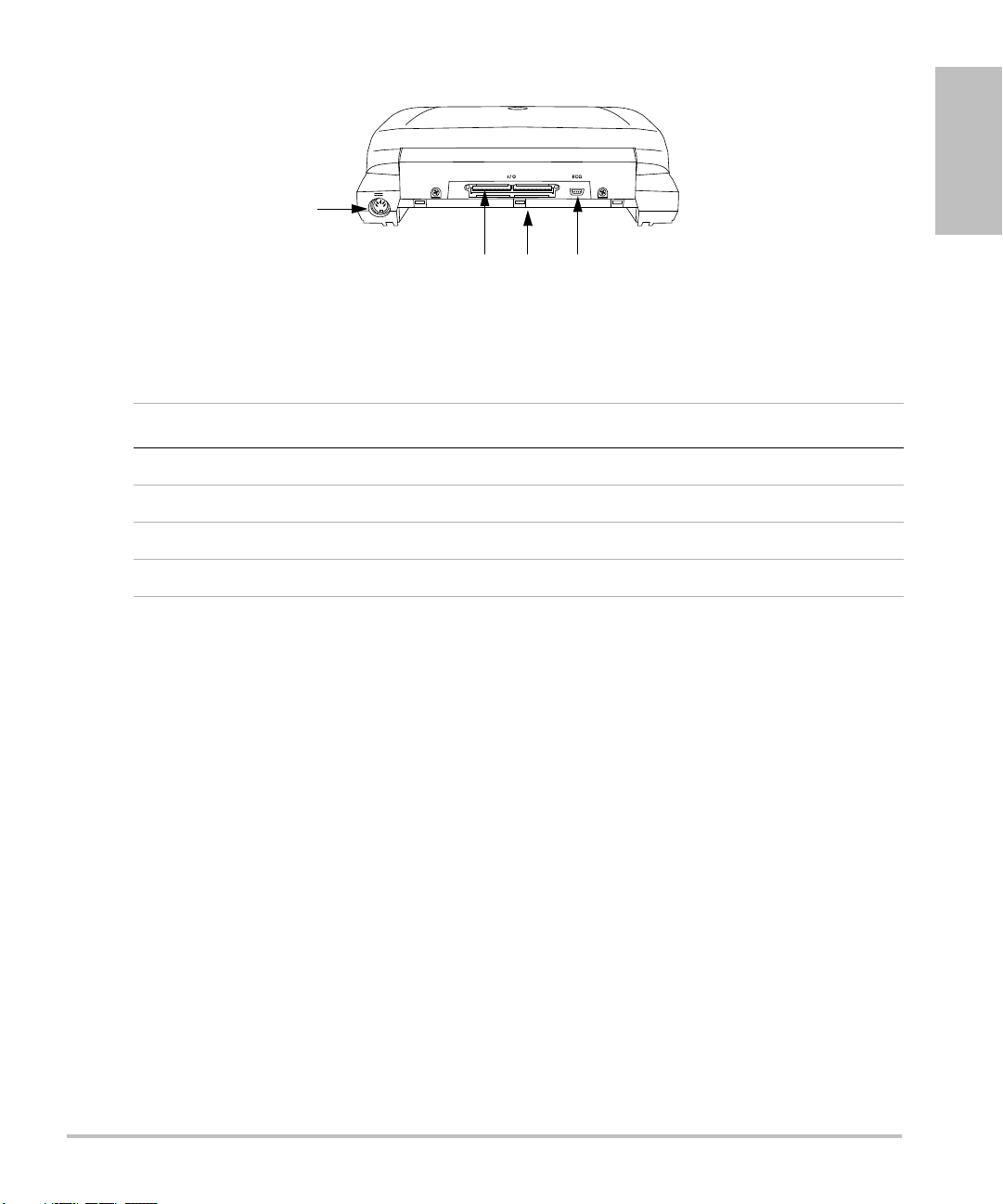
Figure 2 System Back View
1
23 4
Table 2: System Back Connectors
Number Feature
1 DC input connector
2 I/O connector
3Battery
4ECG connector
Introduction
Currently, the system supports the following transducers:
• C11e/8-5 MHz
• C60e/5-2 MHz
•D2/2 MHz
• HFL38/13-6 MHz
•ICT/8-5 MHz
•LAP/12-5 MHz
• L25e /13-6 MHz
•L38e/10-5 MHz
•P10/8-4 MHz
•P17/5-1 MHz
•SLA/13-6 MHz
•SLT/10-5 MHz
• TEE/8-3 MHz
Chapter 1: Introduction 7
Page 18

The ultrasound system may include one or more of the following docking systems:
• Mobile Docking System enhanced (MDSe)
• Mobile Docking System (MDS)
•MDS Lite
See the applicable SonoSite accessory user guide. See Chapter 8, “Specifications” for a complete list
of all system accessories.
System peripherals include medical grade (conforming to the requirements of EN60601-1) and
non-medical (commercial) grade products. See Chapter 8, “Specifications” for a complete list of
compatible peripherals. System setup instructions for the use of peripherals are covered in “System
Setup” on page 24.
Manufacturer’s instructions accompany each peripheral. Instructions for the use of accessories and
peripherals with the system are covered in the applicable SonoSite accessory user guide.
About the System Software
The ultrasound system contains software that controls its operation. A software upgrade may be
required. SonoSite provides you with a CompactFlash card containing the software. Typically new
software provides new capabilities. A single CompactFlash card can be used to update one or more
systems. Software upgrades use the back CompactFlash slot on the right hand side of the system.
CompactFlash cards installed in the front CompactFlash slot do not upgrade the system.
8 Chapter 1: Introduction
Page 19

Chapter 2: Getting Started
This chapter contains information on healthy scanning practices, basic operation, and changing
system settings.
Healthy Scanning Guidelines
These guidelines are intended to assist you in the comfort and effective use of your ultrasound
system.
WAR NIN G:
Use of an ultrasound system may be linked to musculoskeletal disorders
Use of an ultrasound system is defined as the physical interaction between the
operator, the ultrasound system, and the transducer.
When using an ultrasound system, as with many similar physical activities, you may
experience occasional discomfort in your hands, fingers, arms, shoulders, eyes, back,
or other parts of your body. However, if you experience symptoms such as constant
or recurring discomfort, pain, throbbing, aching, tingling, numbness, burning
sensation, or stiffness, do not ignore these warning signs. Promptly see a qualified
health professional. Symptoms such as these can be linked with musculoskeletal
disorders (MSDs). MSDs can be painful and may result in potentially disabling
injuries to the nerves, muscles, tendons, or other parts of the body. Examples of
MSDs include carpal tunnel syndrome and tendonitis.
While researchers are not able to definitively answer many questions about MSDs,
there is a general agreement that certain factors are associated with their
occurrence including: preexisting medical and physical conditions, overall health,
equipment and body position while doing work, frequency of work, duration of
work, and other physical activities that may facilitate the onset of MSDs
chapter provides guidelines that may help you work more comfortably and may
reduce your risk of MSDs
Getting Started
a,b,c
.
d
. This
e,f
.
a. Magnavita, N., L. Bevilacqua, P. Mirk, A. Fileni, and N. Castellino. “Work-related Musculoskeletal Complaints in
Sonologists.” Occupational Environmental Medicine. 41:11 (1999), 981-988.
b. Craig, M. “Sonography: An Occupational Hazard?” Journal of Diagnostic Medical Sonography. 3 (1985),
121-125.
c. Smith, C.S., G.W. Wolf, G. Y. Xie, and M. D. Smith. “Musculoskeletal Pain in Cardiac Ultrasonographers: Results
of a Random Survey.” Journal of American Society of Echocardiography. (May1997), 357-362.
d. Wihlidal, L.M. and S. Kumar. “An Injury Profile of Practicing Diagnostic Medical Sonographers in Alberta.”
International Journal of Industrial Ergonomics. 19 (1997), 205-216.
e. Habes, D.J. and S. Baron. “Health Hazard Report 99-0093-2749.” University of Medicine and Dentistry of New
Jersey. (1999).
f. Vanderpool, H.E., E.A. Friis, B.S. Smith, and K.L. Harms. “Prevalence of Carpal Tunnel Syndrome and Other
Work-related Musculoskeletal Problems in Cardiac Sonographers.” Journal of Medicine. 35:6 (1993), 605-610.
Chapter 2: Getting Started 9
Page 20

Position the System
Promote comfortable shoulder, arm, and hand postures:
• Use a stand to support the weight of the ultrasound system.
Minimize eye strain:
• When the exam/procedure allows, position the system within reach.
• Adjust the angle of the system/display to minimize glare from overhead or outside lighting.
Minimize neck strain:
• If using a stand, adjust the stand height such that the display is at or slightly below eye level.
Position Yourself
Support your back during an exam:
• Use a chair that has support for your lower back.
• Use a chair that adjusts to your work surface height and promotes a natural body posture.
• Use a chair that allows for quick height adjustments.
• Always sit or stand in an upright manner. Avoid bending or stooping.
Minimize reaching and twisting:
• Use a bed that is height adjustable.
• Position the patient as close to you as possible.
• Face forward. Avoid twisting your head or body.
• Move your entire body front to back and position your scanning arm next to or slightly in front of
you.
• Stand for difficult exams to minimize reaching.
Promote comfortable shoulder and arm postures for your scanning arm:
• Keep your elbow close to your side.
• Relax your shoulders in a level position.
• Support your arm using a support cushion or pillow, or rest it on the bed.
Minimize neck bending and twisting:
• Position the ultrasound system/display directly in front of you.
• Provide an auxiliary monitor for patient viewing.
Promote comfortable hand, wrist, and finger postures for your scanning arm:
• Hold the transducer lightly in your fingers.
• Minimize the pressure applied on the patient.
• Keep your wrist in a straight position.
10 Chapter 2: Getting Started
Page 21
Take Breaks
Locking levers
Minimizing scanning time and taking breaks can be very effective in allowing your body to recover
from physical activity, which can help you avoid any MSDs. Some ultrasound tasks may require longer
or more frequent breaks. One way of taking a break is to stop and relax. However, simply changing
tasks can help some muscle groups relax while others remain or become active.
Vary your daily activities:
• Plan your work so there are breaks in between ultrasound exams.
• Work efficiently when performing an ultrasound exam by using the software and hardware
features correctly. Learn more about these features in Chapter 3 of this guide.
• Keep moving. Avoid sustaining the same posture by varying your head, neck, body, arm, and leg
positions.
Exercise
Targeted exercises can strengthen muscle groups, which may help you avoid MSDs. Contact a
qualified health professional to determine stretches and exercises that are right for you.
System Preparation
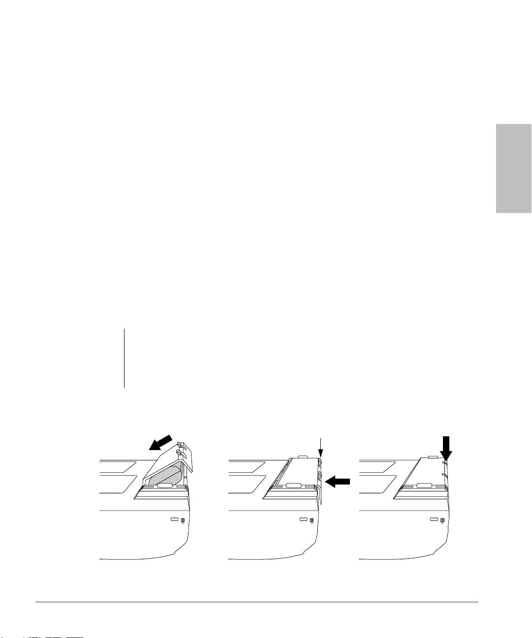
Installing or Removing Battery
The battery comprises six lithium-ion cells plus electronics, a temperature sensor, and battery
contacts.
Getting Started
WAR NIN G:
Figure 1 Insert Battery into System
To avoid injury to the operator and to prevent damage to the ultrasound system,
inspect the battery for leaks prior to installing.
To avoid data loss and conduct a safe system shutdown, always keep a battery in the
system.
Chapter 2: Getting Started 11
Page 22

Install Battery 1 Disconnect the power supply from the ultrasound system.
2 Turn the system upside down.
3 Place the battery into the battery compartment, at a slight angle. See Figure 1
on page 11.
4 Slide the battery forward until it locks into place.
5 Push down on the two locking levers to secure the battery.
Remove
Battery
1 Push up on the two locking levers.
2 Slide the battery back.
3 Lift the battery from the compartment.
Installing or Removing CompactFlash Card
Images and clips are saved to a CompactFlash card and are organized in a patient list. The images and
clips in the patient list are organized alphabetically by the patient name and ID. Images and clips are
archived from the ultrasound system to a PC using a USB, Ethernet connection, wireless, or
CompactFlash card. Images and clips on the CompactFlash card cannot be viewed directly from a
CompactFlash reader.
Install
CompactFlash
Card
Caution:
1 Verify the ejector pin is pushed in completely.
2 Insert the CompactFlash card into the front slot on the ultrasound system. See
Figure 1 on page 6.
• The front slot is used to store images.
• The back slot is used to update systems/transducers and to import/export
DICOM configuration information, OB Tables, and annotation labels.
• The CompactFlash card is ready to use when the save icon and the image
and clip counters are displayed on the screen.
If the CompactFlash icon and image and clip counters are not displayed in the
system status, the CompactFlash card may be defective. Turn the system off and
replace the CompactFlash card.
The CompactFlash card may be restored if it is formatted on a PC. Formatting the
card erases all data. If the card is physically damaged, formatting will not restore it.
WAR NIN G:
12 Chapter 2: Getting Started
To prevent loss of data, (for example, images/clips), or damage to the CompactFlash
card, always turn off the ultrasound system before removing the CompactFlash card.
Page 23

Remove
CompactFlash
Card
1 Turn off the ultrasound system before removing the card.
2 Press the ejector pin in the front card slot to position it to the outside of the
system. See Figure 1 on page 6.
3 Push in the ejector pin to eject the CompactFlash card.
4 Remove the card.
5 Push in the ejector pin to avoid damaging the ejector pin.
Using AC Power/Charging Battery
The battery charges when the system is connected to the AC power supply.
• If the system is off or in the sleep state (display off), a completely discharged battery fully charges
in 2.5 to 3.5 hours.
• If the system is on and in the freeze state, a completely discharged battery fully charges in 5 to
6 hours.
• If the system is in the imaging state, the battery is trickle charged at a very low rate and may take
over 24 hours to charge.
• To minimize recharging time, turn off the system.
Getting Started
Chapter 2: Getting Started 13
Page 24

The system can run on AC power and charge the battery in two ways.
• Connected directly to the system
• Connected to a mini-dock/docking system (See the Mini-Dock User Guide, MDS User Guide, MDSe
User Guide, or MDS Lite User Guide.)
WAR NIN G:
Caution:
Operate
System Using
AC power
The equipment shall be connected to a center-tapped single phase supply circuit
when users in the United States connect the equipment to a 240V supply system.
Verify that the hospital supply voltage corresponds to the power supply voltage
range. See “Electrical” on page 222.
1 Connect the DC power cable from the power supply to the connector on the
system. See Figure 2 on page 7.
2 Connect the AC power cord to the power supply and connect to a
hospital-grade electrical outlet.
Turning System On/Off
Caution:
Turn System
On/Off
Do not use the system if an error message appears on the display. Note the error
code and turn off the system. Call SonoSite or your local representative.
1Locate the Power key on the top left side of the system. See Figure 3 on
page 16.
2 Press the Power key once to turn on and once to turn off.
Wake Up
System
14 Chapter 2: Getting Started
To conserve battery life, the system is configured to go into sleep mode. The system
goes into sleep mode when the lid is closed or if the system has not been touched
for a preset amount of time. Press any key, touch the touchpad, or open the lid to
wake up the system. To adjust the time for sleep delay, see “Audio and B attery ” on
page 31.
Page 25
Connecting or Removing Transducer
WAR NIN G:
Caution:
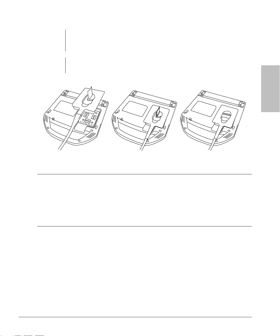
Figure 2 Connect the Transducer
Connect
Transducer to
System
To avoid injury to the patient, do not place the connector on the patient. Operate
the ultrasound system in a docking system or on a flat hard surface to allow air flow
past the connector.
To avoid damaging the transducer connector, do not allow foreign material in the
connector.
1 Turn the system upside down (if not in docking system).
2 Pull the transducer latch up and rotate it clockwise.
3 Align the transducer connector with the connector on the bottom of the
system.
4 Insert the transducer connector into the system connector.
5 Turn the latch counterclockwise.
6 Press the latch down, securing the transducer connector to the system.
Getting Started
Remove
Transducer
1 Pull the latch up and rotate it clockwise.
2 Pull the transducer connector away from the system.
Chapter 2: Getting Started 15
Page 26
System Controls
Update
M Mode
Doppler
Color
2D
Zoom
THI
Depth
Record
Enter
Delete
PictoText
Shift
Caps
Tab
Freeze
Caliper
Calcs
Print
Save
1
2
3
4
6
7
8 9 11 12 13
14
15
17
16
18
19
20
5
10
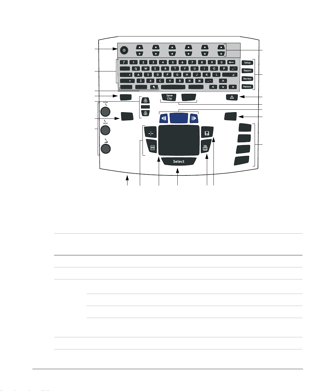
Figure 3 System Controls
Table 1: System Controls
Number
1 Power Turns system on and off.
2 Alphanumeric Use to enter text and numbers.
16 Chapter 2: Getting Started
3
4 THI Turns Tissue Harmonic Imaging on and off.
System
Control
Description
Annotation
Text Turns the keyboard on and off for text entry.
Picto Turns the pictographs/pictograph marker on and off.
Arrow Displays an arrow that can be moved and rotated within the
image area.
Page 27

Table 1: System Controls (Continued)
Number
5
System
Control
Depth
Description
Depth Up Decreases imaging depth.
Depth Down Increases imaging depth.
6 Zoom Magnifies image 2x.
7
Gain
Adjusts the gain applied to the near field of the image.
Near
Adjusts the gain applied to the far field of the image.
Far
Adjusts the overall gain applied to the entire image.
Gain
Note: Some keyboards may have the words instead of symbols.
8AC power
indicator
9Caliper
Calcs
A steady green light indicates AC power is connected. A flashing
green light indicates the system is in sleep mode.
Activates a measurement caliper on the screen.
Turns the calculation menu on and off.
Getting Started
10 Touchpad Use to select, adjust, and move objects on the screen.
11 Select Use to switch between frozen images in duplex and dual screens,
color and Doppler menus, calipers for measurement (Calipers),
pictograph marker position/angle (Picto), and arrow position/
orientation (Arrow).
12 Print Prints the active image to the printer.
13 Save Saves an image to the CompactFlash card and saves
measurements/calculation to the report when configured in
system setup.
14 Menu controls Controls features on the on-screen menu which are adjusted
based on the system state.
Chapter 2: Getting Started 17
Page 28

Table 1: System Controls (Continued)
Number
15
System
Control
Forms
Description
Setup Access to the system settings.
Report Access to the patient report and EMED worksheets.
Review Access to the patient list and saved patient images, and archive
functions.
Patient Access to patient information.
16 (Delta key) Use as a shortcut to existing functionality in the system.
17 Save Clip Saves a clip to the CompactFlash card.
Record Turns DVD/VCR record on and off.
18 Freeze Stops the live imaging and displays a frozen image.
Cine (back/
forward)
Review images stored in the cine buffer; back/forward through
last-in, first-out sequence. All mode images can be stored and
reviewed in the cine buffer.
19 Update Toggles between dual and duplex screens and image modes in
M Mode and Doppler, for example, between D-line and Doppler
spectral trace.
20
Modes
M Mode Turns M Mode on and toggles between M-line and M Mode trace.
Doppler Turns Doppler on and toggles between D-line and Doppler trace.
Color Turns CPD/Color on and off.
2D Turns 2D on.
18 Chapter 2: Getting Started
Page 29
Screen Layout
1
5
4
6
11
10
9
7
3
8
2
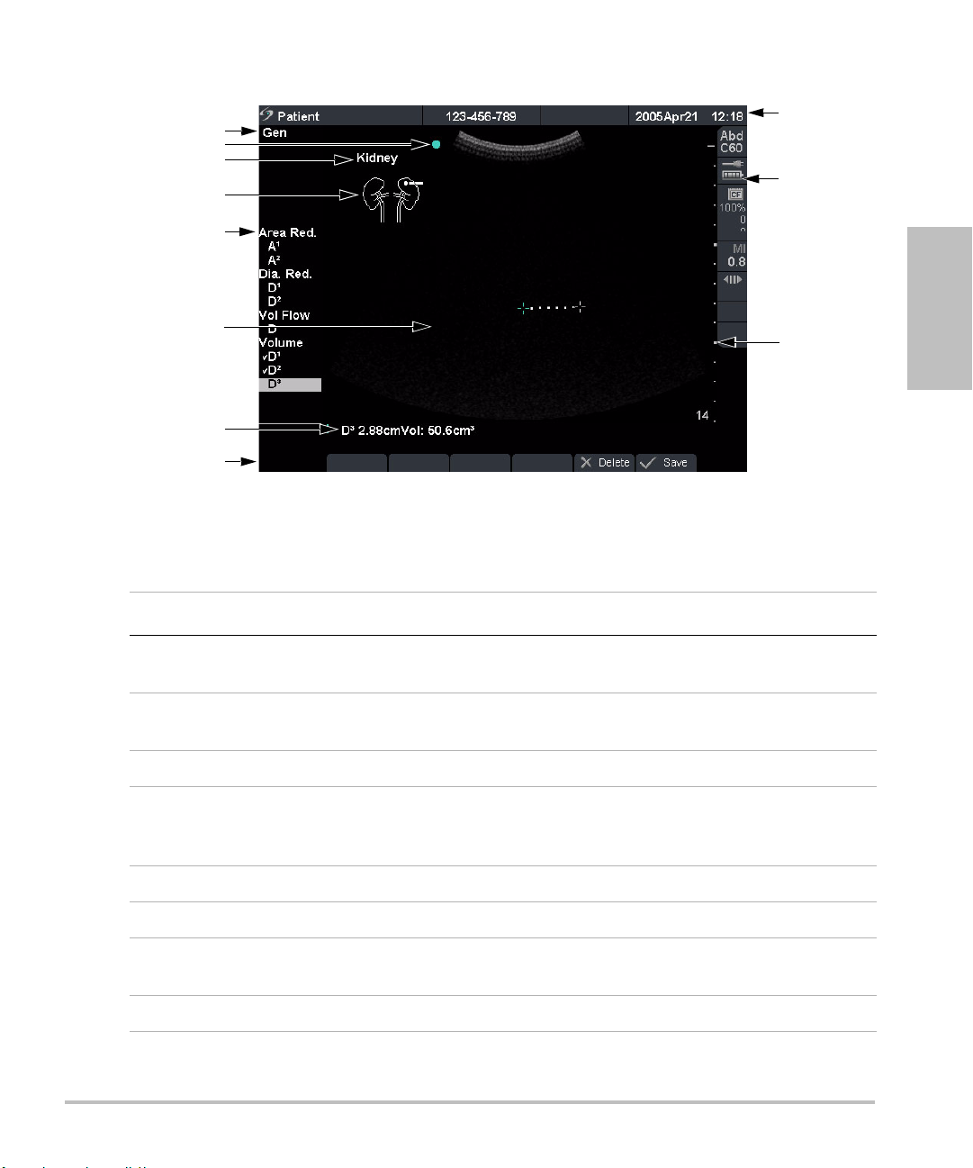
Figure 4 Screen Layout
Table 2: Screen Layout
Getting Started
Number Item Description
1 Mode Data Displays current imaging mode information, for example, Gen,
Res, THI, and PW.
2Orientation
Marker
Provides indication for image orientation. In dual and duplex
images, the orientation marker is green on the active screen.
3 Text Displays text entered using keyboard.
4 Picto Displays pictograph to indicate anatomy and transducer
position. Opens pictograph on-screen menu allowing anatomy
and screen location selection.
5 Calcs Menu Displays available calculations.
6 Image Displays ultrasound image.
7Measurement
Displays current measurement and calculation data.
and Calcs Data
8 On-screen Menu Access to controls for each system state.
Chapter 2: Getting Started 19
Page 30

Table 2: Screen Layout (Continued)
Number Item Description
9 Patient Header Displays current patient name, ID number, institution, user, and
10 System Status Displays information related to system status, for example, exam
11 Depth Marker Displays marks in .5 cm, 1 cm, and 5 cm increments depending
General Interaction
To uc h pa d
The touchpad is used to select, adjust, and move objects on the screen. For example, it controls the
caliper position, CPD/Color box position and size, floating cursor, and more. The arrow keys control
much of the same functionality as the touchpad.
date/time.
type, transducer, AC connected, battery charging, and
CompactFlash card.
on the depth.
20 Chapter 2: Getting Started
Page 31

On-Screen Menus
The on-screen menus, located at the bottom of the screen, provide controls that can be adjusted
based on the system state. For example, in 2D, the following options may be available:
Table 3: On-Screen Menus
Icon Description Values Types
Gen Controls 2D image optimization Res, Gen, Pen Cycle
Dynamic
Range
Dual Displays side-by-side images On-Off
U/L
D/L
D/R
U/R
Brightness Controls display brightness 1-10 Up-Down
Menu Controls
The menu controls consist of six sets of 2-button groups at the top of the control panel. They adjust
the values of each control displayed in the on-screen menu. The buttons function in one of four ways,
depending on context.
Table 4: Menu Control Options
Control Description
Cycle Moves through a list of values, then begins again when the bottom or
Adjusts the image by varying the range
of displayed grays.
Flips the image up/left
Flips the image down/left
Flips the image down/right
Flips the image up/right
top of the list is reached.
Getting Started
(+3)–(-3) Up-Down
Cycle
Up-Down Stops at the top and bottom of a value list, not allowing user to go from
the first to last or last to first value in one button press.
On-Off Turns available features on or off depending on their current state.
Action Performs some action related to an object on the screen.
Chapter 2: Getting Started 21
Page 32

Annotation and Text
2
3
4
5 6 8 9
11
10
1
7
Keyboard Controls
Figure 5 Keyboard Controls
Table 5: Keyboard Controls
Number Key Description
1 Tab Moves cursor among fields in the forms and tabs between text
2 Caps Locks keyboard in caps mode.
3 Shift Allows entry of capitalized characters and international characters.
position in dual screens.
4 Text Turns the keyboard on and off for text entry.
5 Picto Turns pictographs on and off.
6 Arrow Displays an arrow that can be moved and rotated within the image
area.
7 Spacebar Turns the keyboard on for text entry or adds a space with access to
additional on-screen menus (symbols, delete line and done.)
8 Delete Removes all text from the screen during text entry and when in
non-measurement modes.
9 Arrow keys Moves highlighted selection in calculations menus, moves cursor
one space when entering text, moves caliper position, and moves
among pages in image review and reports.
10 Backspace Removes one character to the left of the cursor in text entry mode.
11 Enter Moves cursor among fields in forms and saves calculations to
report.
22 Chapter 2: Getting Started
Page 33

Symbols
Note: Not all of the symbols/special characters are available in fields and forms.
Symbols/special characters can be entered in selected fields and forms:
• Patient Information: Last, First, Middle, ID, Accession, Indications, Procedure ID, User, Reading Dr.,
Referring Dr., and Institution.
• Connectivity (DICOM and SiteLink) Configure: Alias, AE Title.
• Delta Key, Annotations: Text.
• Text mode (Imaging): Annotation field.
Figure 6 Symbols/Special Characters
Getting Started
Forms
Enter Symbol/
Special
Character
A floating cursor is available in the setup, patient, and report forms. The floating cursor allows
interaction through the touchpad and the Select key. For example, in the patient form, placing the
floating cursor over the last name field and pressing the Select key activates that field. Additionally,
the floating cursor can be used to interact with the list and check boxes.
1 Select the desired field and then select Symbols.
2 Click the desired symbol/character.
In the Symbols dialog box, the keyboard controls may also be used.
3Click OK.
Chapter 2: Getting Started 23
Page 34

System Setup
System setup is used to customize the system. Press the Setup key to access and set up the following
system functions:
Administration Configure system to protect patient data by requiring users to log on
Audio, Battery Configure for type of Key click, Audio alert, Sleep delay, and Power
Cardiac Calculations Customize predefined labels to display in Tissue Doppler Imaging
Connectivity Configure Printer, Video Mode, Serial Port, CF Capacity Alert, and
Date and Time Configure Date and Time functions.
Delta Key, Annotations Configure existing system functionality as a shortcut, customize
Display Information Configure information displayed on image: Patient Header, Mode
and enter passwords.
delay.
(TDI) calculation menu and on report page.
Transfer Mode: DICOM or SiteLink setup (DICOM and SiteLink are
optional features).
predefined labels, and set preference for managing text when
unfreezing images.
Data, and System Status.
IMT calculations Customize predefined labels to display in the IMT calculation menu
and on the report page.
OB Calculations Select OB calculation table authors and import/export additional OB
tables.
OB Custom
Measurements
Presets Configure Preset functions: Doppler Scale, Duplex, Live Trace,
System Information Displays system hardware and software versions, and license
Network Status Displays system IP address, Location, WLAN Profile, Active WLAN
Customize system for user-defined measurements to display in the
OB calculations menu and on the report page (OB Custom
Measurements are an optional feature).
Thermal Index, Save Key, Dynamic Range, Units, and Footswitch
settings.
information.
SSID, Ethernet MAC address, and Wireless MAC address.
24 Chapter 2: Getting Started
Page 35

Set Security Settings
Security Setup
WAR NIN G:
SonoSite provides a comprehensive set of tools on the system that allows its customers to meet the
applicable security requirements listed in the HIPAA standard. SonoSite's customers are ultimately
responsible for ensuring the security and protection of all electronic protected health information
collected, stored, reviewed, and transmitted on the system.
Health care providers who maintain or transmit health information are required by
the Health Insurance Portability and Accountability Act (HIPAA) of 1996 and the
European Union Data Protection Directive (95/46/EC) to implement appropriate
procedures: to ensure the integrity and confidentiality of information; to protect
against any reasonably anticipated threats or hazards to the security or integrity of
the information or unauthorized uses or disclosures of the information.
Getting Started
Figure 7 Setup: Administration and Administrator Information
Administrator Login 1 Press the Setup key.
2 Select Administration.
3In Administrator Login, type Administrator in the Name field.
4 Call SonoSite for the password: 1-877-657-8118 (USA and Canada
only).
5 Select Login.
Chapter 2: Getting Started 25
Page 36

Change Administrator
Password
1In User Information, enter your new password in the Password
field.
2 Enter the password again in the Confirm field.
To ensure passwords are secure, it is recommended that passwords
contain characters from the following categories:
• Upper case characters: A-Z
• Lower case characters: a-z
• Numbers: 0-9
The password is case-sensitive.
3In Password changes, click on the check box to allow users access
to change their password or leave unchecked to restrict access.
(Optional)
4 Select Save.
User Login Setting 1In the User Login list, select On or Off.
• Selecting On restricts access to the system and requires the user
to enter a user name and password.
• Selecting Off allows access to the system and does not require
the user to enter a user name and password.
2After making changes in the Administration setup, reboot the
system to log off as administrator.
26 Chapter 2: Getting Started
Page 37

User Setup
Figure 8 Setup: User List Information
Add New User 1 Select New.
Getting Started
2In User Information, enter information in Name, Password, and
Confirm fields.
To ensure passwords are secure, it is recommended that passwords
contain characters from the following categories:
• Upper case characters: A-Z
• Lower case characters: a-z
• Numbers: 0-9
The name and password are case-sensitive.
3In Sonographer, enter the user’s initials to display the information
in the patient header and the sonographer field in the Patient
Information form. (Optional)
4In Administration Access, click the check box to allow users access
to all administration privileges or leave unchecked to restrict
access. (Optional)
5 Select Save.
Modify User Information 1In the User List, select desired user name.
2 Enter the new name.
3 Enter the new password and confirm.
4 Select Save.
Any change to the user name replaces the old name.
Delete User 1In the User List, select the desired user name.
2 Select Delete.
A dialog box is displayed.
3 Select Ye s to delete or No to cancel.
Chapter 2: Getting Started 27
Page 38

Change User Password 1In the User List, select the desired user name.
Done Select Done from the on-screen menu to return to live imaging.
Export or Import User Accounts
Note: Export and import are used to configure multiple systems and to back up user account
information.
Export User Account 1 Insert the CompactFlash card in the back slot of the system. See
Import User Account 1 Insert the CompactFlash card in the back slot of the system. See
2 Enter the new password and confirm.
3 Select Save.
“Installing or Removing CompactFlash Card” on page 12.
2 Press the Setup key.
3 Select Administration.
4 Select Export from the on-screen menu.
All user names and passwords are copied to the CompactFlash
card.
5 Remove the CompactFlash card.
“Installing or Removing CompactFlash Card” on page 12.
2 Press the Setup key.
3 Select Administration.
4 Select Import from the on-screen menu.
• A dialog box is displayed.
• After all user names and passwords are imported, the system
restarts.
• All user names and passwords currently on the system are
replaced with the imported data.
Reset Select Reset from the on-screen menu to return settings for this setup
page to factory default.
28 Chapter 2: Getting Started
Page 39

Export and Clear Event Log
The Event Log collects errors and events and can be exported to a CompactFlash card and read by a
CompactFlash reader.
Figure 9 Event Log
View Event Log 1 Press the Setup key.
Getting Started
2 Select Administration.
3 Select Log from the on-screen menu.
The Event Log is displayed.
4 Select Back to return to the previous menu.
Export Event Log Note: The Event log and the DICOM network log have the same filename
(log.txt). When you export either one to the same CompactFlash card, it
will overwrite the existing log.txt file.
1 Insert the CompactFlash card in the back slot of the system.
2 Select Log and then Export from the on-screen menu.
3 View the files on a CompactFlash reader.
The log is a text file that can be opened by a text file application, for
example, Microsoft Word or Notepad. The log file is named log.txt.
Clear Event Log 1 Select Clear from the on-screen menu.
2 Select Ye s to delete or No to cancel.
Chapter 2: Getting Started 29
Page 40

Login to System as User
Figure 10 User Login and Change Password
Note: User Login is displayed when system access is turned on.
User Login In User Login, enter Name and Password and select OK.
Guest Login In User Login, select Guest.
In Guest mode the user is able to scan but is restricted from accessing system setup
and patient information.
Change
Password
1In User Login, select Password.
2 Enter your old password, new password, confirm the new password and then
select OK.
To ensure passwords are secure, it is recommended that passwords contain
characters from the following categories:
• Upper case characters: A-Z
• Lower case characters: a-z
• Numbers: 0-9
The password is case-sensitive.
30 Chapter 2: Getting Started
Page 41

Audio and Battery
Figure 11 Setup: Audio, Battery
Key Click 1 Press the Setup key.
Beep Alert 1 Press the Setup key.
Getting Started
2 Select Audio, Battery.
3In the Key click list, select On or Off.
2 Select Audio, Battery.
3In the Beep alert list, select On or Off.
Sleep Delay 1 Press the Setup key.
2 Select Audio, Battery.
3In the Sleep delay list, select Off, 5, or 10 minutes.
Power Delay 1 Press the Setup key.
2 Select Audio, Battery.
3In the Power delay list, select Off, 15, or 30 minutes.
Reset Select Reset from the on-screen menu to return settings for this setup
page to factory default.
Chapter 2: Getting Started 31
Page 42

Cardiac Calculations
Figure 12 Setup: Cardiac Calculations
Set Cardiac Calculations 1 Press the Setup key.
2 Select Cardiac Calculations.
3In the TDI Walls lists, select the desired labels for each of the walls.
The labels selected are displayed in the TDI calculation menu and
on the report.
4 Select Done from the on-screen menu.
Reset Select Reset from the on-screen menu to return settings for this setup
page to factory default.
32 Chapter 2: Getting Started
Page 43

Connectivity
Figure 13 Setup: Connectivity, DICOM and SiteLink
Printer 1 Press the Setup key.
Video Mode 1 Press the Setup key.
Getting Started
2 Select Connectivity.
3In the Printer list, select the desired printer from the list of
recommended printers.
2 Select Connectivity.
3In the Video Mode list, select NTSC or PA L for the desired
mini-dock video output.
Serial Port 1 Press the Setup key.
2 Select Connectivity.
3In the Serial Port list, select the desired peripheral: VCR, DVD,
Computer (PC), or Bar Code Scanner.
Note: Because these peripherals use the same RS-232 connector on
the mini-dock, you can connect only one of these peripherals at a
time.
4 Restart the system to activate connectivity to the new peripheral.
5 Attach a serial cable (RS-232) to the serial port from the mini-dock
or docking system to the desired peripheral.
• If PC is selected, the system allows report data to be sent as
ASCII text from the system to a PC.
• Special third party software must be on the PC to acquire, view,
or format the data into a report.
• Check the compatibility of your software with SonoSite
Technical Support.
Chapter 2: Getting Started 33
Page 44

Transfer Mode 1 Press the Setup key.
2 Select Connectivity.
3In the Transfer Mode list, select DICOM or SiteLink.
4 Select DICOM Setup or SiteLink Setup as appropriate.
• If the transfer mode is changed, a dialog box is displayed to
restart the system.
• For more information on setting up DICOM or SiteLink, see
Chapter 5, “Connectivity and Configuration”.
• The settings for SiteLink Image Manager and system
configurations must correspond. See the SiteLink Image
Manager User Guide.
Location 1 Press the Setup key.
2 Select Connectivity.
3In the Locations list, select the desired DICOM or SiteLink location.
• If the Location is changed, a dialog box is displayed to restart
the system.
•See Chapter 5, “Connectivity and Configuration” for configuring
locations in DICOM or SiteLink.
CF Capacity Alert 1 Press the Setup key.
2 Select Connectivity.
3 Select CF Capacity Alert.
When CF Capacity Alert is selected, the system alerts the user if the
Compact Flash card is near capacity at End Exam then deletes
archived patient exams if desired.
Reset Select Reset from the on-screen menu to return settings for this setup
page to factory default.
34 Chapter 2: Getting Started
Page 45

Date and Time
Figure 14 Setup: Date and Time
Getting Started
WAR NIN G:
Date 1 Press the Setup key.
Time 1 Press the Setup key.
Reset Select Reset from the on-screen menu to return settings for this setup
An accurate date and time are critical for accurate obstetrics calculations. Verify that
the date and time are accurate before each use of the system. The system does not
automatically adjust for daylight savings time changes.
2 Select Date and Time.
3In the Date field, enter the current date (year, month, and day).
2 Select Date and Time.
3In the Time field, enter the current time in 24 hour format (hours
and minutes).
page to factory default.
Chapter 2: Getting Started 35
Page 46

Delta Key and Annotation
Figure 15 Setup: Delta Key, Annotations
Delta Key 1 Press the Setup key.
Annotations 1 Press the Setup key.
2 Select Delta Key, Annotations.
3In the Delta Key list, select desired functionality for the Delta key.
The Delta key now controls this function.
2 Select Delta Key, Annotations.
3In the Exam list, select the desired exam type.
4 Select the Group A, B, or C for the predefined labels you want
associated with that exam.
The preset labels show for the selected group.
5 Add a label to a group by selecting the group then entering the
label name in the Te xt field and selecting Add.
6 Rename an existing label by highlighting it, typing the new name
in the Tex t field, and selecting Rename.
7 Move a label within a group by highlighting it and selecting the up
or down arrow.
8 Delete a label from a group by highlighting it and selecting Delete.
Symbols can be used when naming labels. For more information on
using symbols, see “Symbols” on page 23.
36 Chapter 2: Getting Started
Page 47

Unfreeze Preset options for saving text when an image is unfrozen or when
image layout changes.
1 Press the Setup key.
1 Select Delta Key, Annotations.
2In the Unfreeze list, select the desired text state: Keep All Text,
Keep Home Text, or Clear All Text.
• Home text runs to the right of the home cursor position. For
more information on setting the home cursor position, see
“Home/Set” on page 74.
• The default is Keep All Text.
Import Imports and replaces all predefined label groups for all exams with
those from the CF card.
Export Saves and exports all predefined label groups for all exams to the CF
card.
Reset Select Reset from the on-screen menu to return settings for this setup
page to factory default.
Getting Started
Chapter 2: Getting Started 37
Page 48

Display Information
Figure 16 Setup: Display Information
Patient Header 1 Press the Setup key.
Mode Data 1 Press the Setup key.
2 Select Display Information.
3 Select the desired check boxes to display information in the patient
header.
2 Select Display Information.
3 Select the desired check boxes to display imaging information on
the screen.
System Status 1 Press the Setup key.
2 Select Display Information.
3 Select the desired check boxes to display the system status on the
screen.
Reset Select Reset from the on-screen menu to return settings for this setup
page to factory default.
38 Chapter 2: Getting Started
Page 49

IMT Calculations
Figure 17 Setup: IMT Calculations
IMT Calculations 1 Press the Setup key.
Getting Started
2 Select IMT Calculations.
3In the IMT Calculations list, select the desired labels.
• Selecting a label places the measurement on the Calculation
menu and into the report.
• Selecting None removes a label.
4 Enter the desired Region width.
Reset Select Reset from the on-screen menu to return settings for this setup
page to factory default.
Chapter 2: Getting Started 39
Page 50

OB Calculations Authors
Figure 18 Setup: OB Calculations
Gestational Age
Growth Analysis
More Select More to display the list of user-defined custom measurements
Export 1 Insert a blank CompactFlash card in the back slot of the system.
1 Press the Setup key.
2 Select OB Calculations.
3In Gestational Age or Growth Analysis lists, select the desired OB
authors.
• Selecting an author places the measurement on the calculation
menu.
• Selecting None removes the measurement from the calculation
menu.
and to associate a custom table for the custom measurement. This
option is only available when a user-defined custom table has been
created for the custom measurement.
2 Press the Setup key.
3 Select OB Calculations.
4 Select Export from the on-screen menu.
All user-defined tables and measurements are copied to the
CompactFlash card.
40 Chapter 2: Getting Started
Page 51

Import 1 Insert the CompactFlash card in the back slot of the system.
2 Press the Setup key.
3 Select OB Calculations.
4 Select Import from the on-screen menu.
5 Select Ye s to import data or No to cancel.
• After all user-defined tables and measurements are imported,
the system restarts.
• All user-defined tables and measurements currently on the
system are replaced with imported data.
6 Select Done from the on-screen menu to return to live imaging.
Table s Select Tables from the on-screen menu to display system OB tables or
to create custom OB tables. See “OB Custom Tables” on page 43.
Reset Select Reset from the on-screen menu to return settings for this setup
page to factory default.
Getting Started
Chapter 2: Getting Started 41
Page 52

OB Custom Measurements
Figure 19 Setup: OB Custom Measurements
OB Custom
Measurements
Delete OB Custom
Measurement
Table s Select Tables from the on-screen menu to display system OB tables or
1 Press the Setup key.
2 Select OB Custom Meas.
3 Select New.
4In the Name field, enter a unique name.
5In the Type list, select the desired measurement type.
6 Select Save.
• The new measurement is displayed in the calculations menu
and the OB report.
• Up to five custom measurements may be saved.
1 Press the Setup key.
2 Select OB Custom Meas.
3In the Custom Measurements list, highlight the last
measurement.
4 Select Delete Last.
5 Select Ye s to delete the measurement or No to cancel.
If associated tables and report data exist for the measurement, they
are removed from the system.
to create Gestational Age tables for a custom OB measurement. See “OB
Custom Tables” on page 43.
42 Chapter 2: Getting Started
Page 53

OB Custom Tables
Figure 20 Setup: OB Custom Table
Gestational Age Table Measurements: The system provides gestational age measurements by
selected authors for the age table measurements listed in Tab le 6 .
Growth Analysis Table Measurements: The system provides growth graphs or curves for the growth
table measurements listed in Tab le 6.
Table 6: OB Custom Table Measurements
Gestational Age Table Measurements GS, CRL, BPD, OFD, HC, TTD, AC, FTA, FL,
Getting Started
5 additional custom measurement labels
Growth Analysis Table Measurements BPD, HC, AC, FL, EFW
WAR NIN G:
View OB Tables 1 Press the Setup key.
Prior to use, verify custom table data entries are correct. The system does not
confirm the accuracy of the custom table data entered by the user.
2 Select OB Custom Meas. or OB Calculations.
3 Select Tables from the on-screen menu.
4 Select the desired table (Age or Growth) and measurement/author.
Chapter 2: Getting Started 43
Page 54

Create New OB Custom
Table s
1 Press the Setup key.
2 Select OB Custom Meas. or OB Calculations.
3 Select Tables from the on-screen menu.
4 Select the desired table (Age or Growth).
5 In the measurement list, select the desired measurement for the
custom table.
6 Select New from the on-screen menu.
7In the Author field, enter a unique name.
8 Enter the data.
9 Select Save from the on-screen menu.
Two custom tables may be created for each OB measurement.
• To display the measurement for the custom table in the
calculation menu, see “OB Calculations Authors” on page 40
and select More.
• Growth analysis tables cannot be created for custom OB
measurements.
Edit OB Custom Tables 1 Press the Setup key.
2 Select OB Custom Meas. or OB Calculations.
3 Select Tables from the on-screen menu.
4 Select the desired custom OB table.
5 Select Edit and enter data and then select Save from the on-screen
menu.
Delete OB Custom Tables 1 Press the Setup key.
2 Select OB Custom Meas. or OB Calculations.
3 Select Tables from the on-screen menu.
4 Select the desired custom OB table.
5 Select Delete from the on-screen menu to remove the custom
table from the system.
44 Chapter 2: Getting Started
Page 55

Presets
Getting Started
Figure 21 Setup: Presets
Doppler Scale 1 Press the Setup key.
2 Select Presets.
3In the Doppler Scale list, select cm/s or kHz.
Duplex 1 Press the Setup key.
2 Select Presets.
3In the Duplex list, select the desired image display.
• Full 2D, Full Trace
• 1/3 2D, 2/3 Trace
• 1/2 2D, 1/2 Trace
Live Trace 1 Press the Setup key.
2 Select Presets.
3In the Live Trace list, select Peak or Mean.
Thermal Index 1 Press the Setup key.
2 Select Presets.
3In the Thermal Index list, select TIS, TIB, or TIC.
The Thermal Index default setting is based on exam type.
•OB: TIB
•TCD: TIC
•All others: TIS
Chapter 2: Getting Started 45
Page 56

Save Key 1 Press the Setup key.
2 Select Presets.
3In the Save Key list, select Image Only or Image/Calcs to
designate the function of the Save Key.
• Selecting Image Only allows the Save Key to save the image to
the CompactFlash card.
• Selecting Image/Calcs allows the Save Key to save the image to
the CompactFlash card and to save the current calculation to
the report.
Dynamic Range 1 Select the desired exam type. See “Exam” on page 51.
2 Press the Setup key.
3 Select Presets.
4In the Dynamic Range list, select the setting: -3, -2, -1, 0, +1, +2,
+3.
Negative numbers show higher contrast images and positive
numbers show lower contrast images.
Units 1 Press the Setup key.
2 Select Presets.
3In the Units list, select the desired units for patient height and
weight: in/ft/lbs or cm/m/kg.
Units settings available in cardiac exams only.
Footswitch
(Left/Right)
1 Press the Setup key.
2 Select Presets.
3In the Footswitch (L) and Footswitch (R) list, select desired
functionality for the left and right footswitch: Save Clip, Record,
Freeze, Save Image, Print.
Reset Select Reset from the on-screen menu to return settings for this setup
page to factory default.
46 Chapter 2: Getting Started
Page 57

System Information
Figure 22 Setup: System Information
System Information 1 Press the Setup key.
Getting Started
2 Select System Information.
To install a license key see “Installing a License Key” on page 185.
Change to Default
Settings
1 Turn the system off.
2 Connect the system to AC power. See “Operate System Using AC
power” on page 14.
3 Simultaneously press and release 1 and the Power key.
• The system beeps several times, and the system displays the
default settings.
• Default settings are set at the factory and cannot be changed
by the user.
Chapter 2: Getting Started 47
Page 58

Network Status
Figure 23 Setup: Network Status
Network Status 1 Press the Setup key.
2 Select Network Status.
48 Chapter 2: Getting Started
Page 59

Chapter 3: Imaging
Patient Information
The patient information form allows information to be entered into the system for the patient exam.
• Information which can be entered includes patient demographics, exam information, and clinical
information.
• This information is automatically placed on the last page of the patient report.
• Once a patient is entered, all saved images are linked to that patient.
• To end the exam, a New Patient can be created or End Exam can be selected.
• Patient information can be edited during the exam by pressing the Patient key. However, if the
patient name, ID, or Accession changes, a new patient is created.
Imaging
Figure 1 Patient Information Form
New Patient 1 Press the Patient key.
2 Select New from the on-screen menu.
• This clears the existing patient information.
• Selecting new patient erases any previously entered information,
including any calculations and report pages. To save this
information, save the screen for each item, for example, report
pages, patient information, calculations, and graphs.
Chapter 3: Imaging 49
Page 60

New Patient
(continued)
3 Enter information into appropriate fields.
The patient information fields vary based on the selected exam type.
•Patient
• Patient: Enter Last, First, Middle Names, and ID.
• Accession: Enter number, if applicable.
• Date of birth: Enter (YYYY/MM/DD).
• Gender: Select Female, Male, other, or leave blank.
• Indications: Enter desired text.
• Symbols: See “Symbols” on page 23.
•More
• User: Enter initials.
• Reading Dr. and Referring Dr.: Enter names.
• Institution: Enter name.
All patient information can be edited up until the first image is saved.
After the first image is saved, the Patient Name, ID, and Accession
number cannot be modified. Modifying these fields closes the current
patient exam and starts a new exam.
Select Back from the on-screen menu to save information and return to
previous menu.
50 Chapter 3: Imaging
Page 61

New Patient
(continued)
•Exam
• Typ e: Select desired exam type.
• LMP or Estab. DD: Select LMP or Estab. DD then enter either last
menstrual period or established due date (YYYY/MM/DD). (Estab.DD
only in OB exam.) The date for LMP must precede the current system
date.
• Twi ns: Select the Twins check box to display Twin A and Twin B
measurements on the calculation menu (only in OB exam and
report).
• Previous Exams (only in OB exam).
• Enter data from previous exams. Data from five previous exams
may be entered.
•For twins, select Twin A/B from the on-screen menu to enter
data for each twin.
The date for a previous exam must precede the current system date.
Select Back from the on-screen menu to save information and return to
previous menu.
• BP: Enter blood pressure (only in cardiac, vascular, and IMT exams).
• HR: Enter the Heart Rate (only in cardiac, vascular, and IMT exams). If
the heart rate is obtained and saved using M Mode, the values
override the number entered on the patient information screen.
• Height: Enter the patient height in feet and inches or meters and
centimeters (only in cardiac exam).
• Weight: Enter the patient weight in pounds or kilos (only in cardiac
exam).
• BSA (Body Surface Area): This number is automatically generated
after height and weight are entered (only in cardiac exam).
• Ethnicity: Select the applicable ethnic origin (only in IMT exam).
Imaging
End Exam 1 Press the Patient key.
2 Select End Exam from the on-screen menu to close the current patient
exam.
Selecting End Exam, selecting New Patient, or modifying patient name
or ID erases any previously entered information, including any
calculations and report page. To save this information, save the screen
for each item, for example, report pages, patient information, and
calculations.
Cancel Select Cancel from the on-screen menu to undo any changes to the patient
information form and return to the previous imaging state.
Pressing Cancel does not close the current patient exam.
Chapter 3: Imaging 51
Page 62

Done Select Done from the on-screen menu to save information and return to the
previous imaging state.
• Information is saved when exiting the patient information form unless
Cancel is selected from the on-screen menu.
• If any changes are made to the current patient’s name, ID, or accession
number, that patient exam is closed and a new one is started.
Transducer, Exam Type, and Imaging Mode
The system has various configurations and options. All are described in this user guide and may not
apply to your system. System features depend on your configuration, transducer, and exam type.
WAR NIN G:
The following table describes the abbreviations for exam types.
The diagnostic capability differs for each transducer, exam type, and imaging mode.
Verify your system’s capabilities prior to diagnosis.
Transducers have been developed to specific criteria depending on their
application. This criteria includes biocompatability requirements.
To avoid injury to the patient, use only an orbital exam type (Orb) when performing
imaging through the eye. The FDA has established lower acoustic energy limits for
opthalmic use. The system will not exceed these limits only if the Orb exam type is
selected.
Table 1: Exam Type Abbreviations
Abbreviation Exam Type
Abd Abdomen
Bre Breast
Crd Cardiac
Gyn Gynecology
Hep Hepatic
IMT Intima Media Thickness
Msk Muscle
Neo Neonatal
Nrv Nerve
OB Obstetrical
Orb Orbital
52 Chapter 3: Imaging
Page 63

Table 1: Exam Type Abbreviations (Continued)
Abbreviation Exam Type
Pel Pelvic
SmP Small Parts
Sup Superficial
TCD Transcranial Doppler
Vas Vascular
The following table describes the transducer’s exam type and imaging mode that may be available
with your system.
• The optimization settings for 2D are Res, Gen, and Pen.
• The optimization settings for color power Doppler (CPD) and color Doppler (Color) are low,
medium, and high (flow sensitivity) with a range of PRF settings for Color depending on the
application.
Table 2: Transducer, Exam Type, and Imaging Mode
Imaging Mode
Imaging
Trans-
ducer
Exam
Typ e
2D/
MM
THI
2DMB2D
S
CPD Color PW
TDI
PW
CW
C11e Abd X — — X X X X — —
Nrv X — — X X X X — —
C60e OB X X — X X X X — —
Gyn X X — X X X X — —
Abd X X — X X X X — —
D2 Crd — — — — — — — — X
HFL38 Bre X — X X X X X — —
SmP X — X X X X X — —
Vas X — X X X X X — —
IMT X — X X X X X — —
Nrv X — X X X X X — —
Chapter 3: Imaging 53
Page 64

Table 2: Transducer, Exam Type, and Imaging Mode (Continued)
Imaging Mode
Tra ns-
ducer
Exam
Typ e
2D/
MM
THI
2DMB2D
S
CPD Color PW
TDI
PW
CW
ICTe Gyn X — — — X X X — —
OB X — — — X X X — —
L25e Msk X — X X X X X — —
Vas X — X X X X X — —
Nrv X — X X X X X — —
Sup X — X X X X X — —
L38e Bre X — — X X X X — —
SmP X — — X X X X — —
Vas X — — X X X X — —
IMT X — — X X X X — —
Nrv X — — X X X X — —
LAP Abd X — — — X X X — —
Pel X — — — X X X — —
P10 Crd X — — X — X X X X
Neo X — — X X X X — —
Abd X — — X X X X — —
Vas X — — X X X X — —
Nrv X — — X X X X — —
P17 Abd X X — X X X X — —
OB X X — X X X X — —
Crd X X — X — X X X X
TCD X — — X X X X — —
Orb X — — X X X X — —
54 Chapter 3: Imaging
Page 65

Table 2: Transducer, Exam Type, and Imaging Mode (Continued)
Imaging Mode
Trans-
ducer
Exam
Typ e
2D/
MM
SLA Msk X — — X X X X — —
Sup X — — X X X X — —
Vas X — — X X X X — —
Nrv X — — X X X X — —
SLT Abd X — — — X X X — —
Hep X — — — X X X — —
TEE Crd X — — — — X X X X
Transducer Preparation
WAR NIN G:
Caution:
Some transducer sheaths contain natural rubber latex and talc, which can cause
allergic reactions in some individuals. Refer to 21 CFR 801.437, User labeling for
devices that contain natural rubber.
Some gels and sterilants can cause an allergic reaction on some individuals.
To avoid damage to the transducer, use only gels recommended by SonoSite. Using
gels other than the one recommended by SonoSite can damage the transducer and
void the warranty. If you have questions about gel compatibility, contact SonoSite or
your local representative.
THI
2DMB2D
S
CPD Color PW
TDI
PW
CW
Imaging
SonoSite recommends you clean transducers after each use. See “Cleaning and
Disinfecting Transducers” on page 188.
Acoustic coupling gel must be used during exams. Although most gels provide suitable acoustic
coupling, some gels are incompatible with some transducer materials. SonoSite recommends
Aquasonic
®
gel and a sample is provided with the system.
Chapter 3: Imaging 55
Page 66

General Use
Apply Gel Apply a liberal amount of gel between the transducer and the body.
Invasive or Surgical Use
WAR NIN G:
Install Transducer
Sheath
To prevent contamination, the use of sterile transducer sheaths and sterile coupling
gel is recommended for clinical applications of an invasive or surgical nature. Do not
apply the transducer sheath and gel until you are ready to perform the procedure.
Note: SonoSite recommends the use of market-cleared, transducer sheaths for
intracavitary or surgical applications.
1 Place gel inside the sheath.
2 Insert the transducer into the sheath.
To lessen the risk of contamination, install the sheath only when you are
ready to perform the procedure.
3 Pull the sheath over the transducer and cable until the sheath is fully
extended.
4 Secure the sheath using the bands supplied with the sheath.
5 Check for and eliminate bubbles between the face of the transducer and
the sheath.
If any bubbles are present between the face of the transducer and the
sheath, the ultrasound image may be affected.
6 Inspect the sheath to ensure there are no holes or tears.
56 Chapter 3: Imaging
Page 67

Modes
2D Imaging
The system has advanced image optimization technology that greatly simplifies user controls. To
achieve the best possible image quality, it is important to properly adjust the display brightness, gain,
depth settings, and exam type.
It is also important to select an optimization setting that best matches your needs.
The system has a high-performance, liquid crystal display (LCD). To optimize image quality, adjust the
display for viewing angle, and brightness.
Each time you turn the system on, the 2D image is displayed. It displays echoes in two dimensions on
the display by assigning a brightness level based on the echo signal amplitude. This is the system’s
default imaging mode. When imaging in another mode, you may return to 2D imaging by pressing
the 2D key. If the system does not return to 2D imaging after pressing the 2D key, ensure the system
is in live imaging.
Imaging
Figure 2 2D Image
Optimize Select the desired optimization setting from the on-screen menu.
• Res provides the best possible resolution.
• Gen provides a balance between resolution and penetration.
• Pen provides the best possible penetration.
Some of the parameters that are optimized to provide the best image
include: focal zones, aperture size, frequency (center and bandwidth), and
waveform. They cannot be adjusted by the user.
Dynamic
Range
Select the desired dynamic range setting from the on-screen menu to
adjust grayscale range: -3, -2, -1, 0, +1, +2, +3.
• The positive range increases and the negative range decreases the
number of grays displayed.
• A beep sounds when the minimum or maximum of the range is reached.
Chapter 3: Imaging 57
Page 68

Dual Images 1 Select Dual from the on-screen menu to display side-by-side 2D images.
2 Press the Update key to display the second screen and to toggle
between the screens.
With both images frozen, press the Update key to toggle between the
images.
3 Select Dual from the on-screen menu or press the 2D key to return to
full screen 2D imaging.
LVO ( Left
Ventric ular
Opacification)
This feature depends on transducer and exam type.
Use LVO for cardiac exams in 2D mode when using an imaging contrast
agent. LVO lowers the mechanical index (MI) of the system to enhance
visualization of the contrast agent and endocardial border.
1 On a 2D image, select LVO On on page 2 of the on-screen menu to turn
on LVO.
2 Select LVO Off to turn off this option.
Orientation Select from four image orientations: Up/Right, Up/Left, Down/Left,
Down/Right.
Brightness Select the desired brightness setting from the on-screen menu to adjust
display brightness: 1-10.
• A beep sounds when the minimum or maximum of the range is reached.
• The display brightness affects battery life. To conserve battery life, adjust
brightness to a lower setting.
Biopsy This feature depends on transducer type. Biopsy is not available when ECG
cable is connected.
Select Biopsy from the on-screen menu to display biopsy guidelines. Select
again to turn off.
On the P10 and P17 transducers, the biopsy guides are displayed when the
bracket is installed correctly. If the bracket is not installed correctly, the
biopsy feature is not available, and a dialog box is displayed to check
installation of the bracket. See “Needle Guidance” on page 78 and Biopsy
User Guide for more information.
Guide This feature depends on transducer and exam type.
Select Guide from the on-screen menu to turn on the guideline and select
again to turn off.
SonoRES (S) This feature is optional and depends on transducer and exam type. When
both 2D image enhancements are available, SonoRES® image enhancement
capability and SonoMB™ multi-beam technology share the same on-screen
menu. See “Transducer, Exam Type, and Imaging Mode” on page 53.
Select S from the on-screen menu to turn on SonoRES.
• When SonoRES is on, an S is displayed in the upper left corner of the
screen.
• SonoRES is available only in 2D imaging and M Mode.
58 Chapter 3: Imaging
Page 69

SonoMB (MB) This feature depends on transducer and exam type. When both 2D image
enhancements are available, SonoRES and SonoMB share the same
on-screen menu. See “Transducer, Exam Type, and Imaging Mode” on
page 53.
SonoMB is on when available.
• When SonoMB is on, MB is displayed in the upper left corner of the screen.
• SonoMB is available only in 2D imaging.
• If SonoMB is available on the transducer, ECG monitoring is not available.
ECG This feature is optional and requires a SonoSite ECG cable.
1 Connect the ECG cable. See Figure 2, “System Back View” on page 7.
2 Select ECG from the on-screen menu to display the ECG trace. See “ECG
Monitoring” on page 76.
If SonoMB is available on the transducer, ECG monitoring is not available.
Clips This feature is optional.
Select Clips from the on-screen menu to display the clips menu. See “Clips”
on page 68.
Gain Tu rn th e Near, Far, or Gain knobs (on the lower left side of the control panel)
to increase or decrease the amount of gain applied to the near field, far field,
or the overall image. Near and far correspond to the time gain compensation
(TGC) controls found on other ultrasound systems.
Auto Gain This feature depends on transducer type.
Select Auto Gain from the on-screen menu. Auto Gain automatically adjusts
gain each time it is selected.
Imaging
Depth The vertical depth scale is marked in .5 cm, 1 cm, and 5 cm increments,
depending on the depth.
Press the Depth ke y up to de crea se or dow n to increase the displayed depth.
• As you adjust the depth, the maximum depth number changes in the
lower right corner of the screen.
• A beep sounds when the minimum or maximum of the range is reached.
Tissue
Harmonic
Imaging
This feature is optional and depends on transducer and exam type.
1 Press the THI key to turn on THI.
THI is displayed in the top left portion of the screen next to the
optimization setting.
2 Press the THI key again to turn off THI.
The THI icon is removed from the screen.
Chapter 3: Imaging 59
Page 70

Zoom 1 Press the Zoom key.
A region of interest (ROI) box is displayed on the screen.
2Use the Touchpad to position and size the ROI box within the image
area.
3 Press the Zoom key again.
The image is magnified by a factor of two inside the ROI box.
4 Press the Zoom key again to exit zoom.
To exit any zoomed state and return to 2D live in 1x, press the 2D key.
Zoom Pan Note: Panning is available on a frozen, zoomed image. You cannot pan on a
frozen image in Dual.
1 On a frozen 2D image, press the Zoom key.
A zoom box is displayed on the screen.
2Use the Touchpad to position the zoom box within the image area.
3 Press the Zoom key again.
The image is magnified by a factor of two at the position of the zoom
box.
4Use the Touchpad to pan the image up/down and left/right.
5 Press the Zoom key again to exit zoom.
Freeze 1 Press the Freeze key.
The cine icon and frame number are displayed in the system status area
of the screen.
2 Press the Freeze key again to return to live imaging.
The cine icon is removed from the system status area of the screen and
live imaging resumes.
Cine Buffer On a frozen image, press the Cine keys to view individual frames in the cine
buffer.
• The frame number changes dynamically as the cine key is pressed.
• The total number of frames in the buffer is displayed in the system status
under the freeze icon.
60 Chapter 3: Imaging
Page 71

MMode Imaging
The following instructions cover Motion mode (M Mode) imaging. See “2D Imaging” on page 57 for
instructions about depth and optimization.
MMode M-Line
Figure 3 M Mode M-Line
M-Line 1 Press the MMode key for the M-line.
Imaging
If M Mode does not come on, make sure the system is in live imaging.
2Use the Touchpad to position the M- line over the area of interest on the
image.
• Depth changes are not available in M Mode trace.
• Adjust the depth prior to activating the M Mode trace.
Chapter 3: Imaging 61
Page 72

MMode Trace
Figure 4 M Mode Trace Image
MMode
Tra ce
Sweep Speed Select the desired sweep speed from the on-screen menu (slow, med, fast).
Gain Turn the Near, Far, or Gain knobs (on the lower left side of the control panel)
Freeze 1 Press the Freeze key.
Cine Buffer On a frozen image, press the Cine keys to view the trace at different points in
1 Press the MMode key again to acquire the M Mode trace.
The time scale at the top of the trace has small marks at 200 ms intervals
and large marks at one second intervals.
2 Press the Update key to toggle between the M-line and trace.
3 In duplex, press the MMode key to return to the full screen M-line.
You can choose from one of three layouts. For duplex imaging, see
“Duplex” on page 45.
to increase or decrease the amount of gain applied to the near field, far field,
or the overall image. Near and far correspond to the time gain compensation
(TGC) controls found on other ultrasound systems.
2 Press the Freeze key again to return to live imaging.
• The cine icon is removed from the system status area of the screen
and live imaging resumes.
• On the frozen M Mode image, press the MMode key to display the
associated frozen 2D image with the M-line, or press the Update key
to display the 2D live image with the M-line.
time.
2D Imaging Press the 2D key to return to 2D imaging.
62 Chapter 3: Imaging
Page 73

Color Doppler Imaging
Note: Color power Doppler (CPD) and color Doppler (Color) are optional features and depend on
transducer and exam type.
The following instructions cover CPD and Color imaging.
Figure 5 Color Image
CPD or Color 1 Press the Color key for CPD or Color.
Imaging
A ROI box is displayed in the center of the 2D image.
2 Select CPD or Color from the on-screen menu.
• The current setting is displayed in the upper left corner of the screen
and in the on-screen menu.
• In Color or CPD mode, the Color indicator bar is displayed in the
upper left corner of the screen. The Color bar displays velocity in
cm/s in Color mode only.
ROI Box 1Use the To u c hp a d to position or change the size of the ROI box.
While moving or changing the size of the ROI box, a green outline of the
new position or the new size is displayed as it moves on the display.
2 Press the Select key to toggle between the position and size of the ROI
box.
The ROI box indicator on the left side of the screen is highlighted green
to show which function the touchpad is controlling.
Color
Suppress
1 Select Color Suppress from the on-screen menu to hide or show color
information when in Color or CPD mode.
2 Select Hide or Show while in live or frozen imaging.
• The setting shown on the on-screen menu is the current state.
• Color Suppress returns to default state when returning to live
imaging from a frozen state.
Chapter 3: Imaging 63
Page 74

Flow
Sensitivity
Select the desired flow sensitivity from the on-screen menu.
• Low optimizes the system for low flow states.
• Med optimizes the system for medium flow states.
• High optimizes the system for high flow states.
The current setting is displayed in the top left portion of the screen and in
the on-screen menu.
PRF Scale Note: This menu option is available in Color and in CPD on select transducers.
Select the desired pulse repetition frequency (PRF) setting from the
on-screen menu.
• A beep sounds when the minimum or maximum of the range is reached
• There is a wide range of PRF settings for each flow sensitivity selection.
Wall Filter Note: This menu option is available in Color and in CPD on select transducers.
Select the desired wall filter setting from the on-screen menu: low, med,
high.
Steering Note: This menu option is available only on select transducers.
Select the desired steering angle setting from the on-screen menu.
This automatically changes pulsed wave (PW) Doppler angle correction to
the optimum setting.
• Steering angle of -15 degrees has an angle correction of -60 degrees.
• Steering angle of 0 degrees has an angle correction of 0 degrees.
• Steering angle of +15 degrees has an angle correction of +60 degrees.
If two modes are active (CPD/Color and PW/CW Doppler) press the Select
key to toggle between the on-screen menus.
Varianc e Note: This menu option is available only for cardiac exams.
Select Variance from the on-screen menu to turn on.
Invert Select Invert from the on-screen menu to switch the displayed direction of
flow.
Invert is only displayed when Color is selected.
Gain Turn the Gain knob (on the lower left side of the control panel) to increase
or decrease the amount of color gain applied to the CPD or Color ROI box.
While in CPD or Color imaging, Near and Far knobs affect only the 2D image.
2D Imaging Press the 2D or Color key to return to 2D imaging.
If two modes are active (CPD/Color and PW Doppler) press the Select key to
toggle between on-screen menus.
64 Chapter 3: Imaging
Page 75

Pulsed Wave (PW) and Continuous Wave (CW) Doppler Imaging
Note: PW Doppler and CW Doppler are optional features and depend on transducer and exam type.
The following instructions cover PW and CW Doppler imaging.
Doppler D-Line
Figure 6 Doppler with D-Line Image and ROI Box
D-Line 1 Press the Doppler key for the D-line.
2Use the To u ch p a d to position the D-line over the area of interest on the
image.
3 Press the Select key to set the D-line and to toggle between the D-line
and angle correction.
• An indicator on the left side of the screen is highlighted green to
show which function the touchpad is controlling.
• If PW or CW Doppler mode does not come on, make sure the system
is in live imaging.
• The color ROI box is tied to the D-line.
Imaging
PW/CW
Doppler
Note: CW Doppler is available only in cardiac exams.
1 Press the Doppler key.
2 Select PW from the on-screen menu to toggle between PW Doppler and
CW Doppler.
Chapter 3: Imaging 65
Page 76

Angle
Correction
Note: This menu option is available only in PW Doppler.
There are two ways to adjust the angle correction in PW Doppler imaging.
Select Angle Correction from the on-screen menu to adjust the angle
correction to 0, +60, or -60 degrees.
OR
1 Press the Select key to highlight angle correction and to toggle
between the D-line and angle correction.
An indicator on the left side of the screen is highlighted green to show
which function the touchpad is controlling.
2Use the To u ch p a d to adjust the angle in two degree increments from
-74 to +74 degrees.
3 Press the Select key again to set the desired angle.
Gate Size Note: This menu option is available only in PW Doppler.
Select the desired gate size setting from the on-screen menu.
• A beep sounds when the minimum or maximum of the range is reached.
• Gate size options vary with transducer and exam type.
Tissue
Doppler
Imaging
(TDI)
Doppler Gate
Depth
Note: This menu option is available only in PW Doppler and cardiac exams.
Select TDI from the on-screen menu to turn on tissue Doppler imaging.
• TDI displays in the upper left corner of the screen when TDI is on.
• The default for TDI is off.
Note: This menu option is available only in TCD/Orb exams.
1 Locate the Doppler gate depth indicator at the bottom right of the
screen.
Doppler gate depth measures the depth of the center of the gate in the
Doppler image.
2Use the To u ch p a d to select the desired depth.
Steering Note: This menu option is available only on select transducers.
Select the desired steering angle setting from the on-screen menu.
This automatically changes PW angle correction to the optimum setting.
• Steering angle of -15 degrees has an angle correction of -60 degrees.
• Steering angle of 0 degrees has an angle correction of 0 degrees.
• Steering angle of +15 degrees has an angle correction of +60 degrees.
The angle correction can be adjusted manually after steering has been
selected. (See “Angle Correction.”)
If two modes are active (CPD/Color and PW/CW Doppler) press the Select
key to toggle between on-screen menus.
66 Chapter 3: Imaging
Page 77

Doppler Spectral Trace
Figure 7 Doppler Trace Image
Spectral
Tra ce
1 Press the Doppler key again to acquire the Doppler trace.
2 Press the Update key to toggle between the 2D/D-line and trace.
3 In duplex, press the Doppler key to return to the full screen D-line.
• The time scale at the top of the trace has small marks at 200 ms
intervals and large marks at one second intervals.
• You can choose from one of three screen layouts. For duplex imaging
see “Duplex” on page 45.
Scale Select the desired scale/pulse repetition frequency (PRF) setting from the
on-screen menu. A beep sounds when the minimum or maximum of the
range is reached.
Line Select the desired baseline position from the on-screen menu.
Baseline can be adjusted on a frozen trace if Live Trace is not displayed.
Invert Select Invert from the on-screen menu to vertically flip the spectral trace.
Invert can be adjusted on a frozen trace if Live Trace is not displayed.
Volume Select the desired Doppler volume setting from the on-screen menu to
increase or decrease Doppler speaker volume (0-10). A beep sounds when
the minimum or maximum of the range is reached.
Wall Filter Select the desired wall filter setting from the on-screen menu: low, med,
high.
Sweep Speed Select the desired sweep speed from the on-screen menu: slow, med, fast.
Imaging
Live Trace Select Trace from the on-screen menu to display a live trace of the peak or
mean. See “Live Trace” on page 45.
Gain Turn the Gain knob to increase or decrease the amount of Doppler gain.
Chapter 3: Imaging 67
Page 78

Clips
Freeze 1 Press the Freeze key.
The cine icon is displayed in the system status area of the screen.
2 Press the Freeze key again to return to live imaging.
The cine icon is removed from the system status area of the screen and
live imaging resumes.
Cine Buffer On a frozen image, press the Cine keys to view the trace at different points in
time.
2D Imaging Press the 2D key to return to 2D imaging.
Note: This feature is optional.
Time/ECG Select Clips from the on-screen menu.
• Select Time from the on-screen menu if desired acquisition is based on
number of seconds. Select the desired time duration: 2s, 4s, 6s.
• Select ECG from the on-screen menu if desired acquisition is based on the
number of heart beats. Select the desired number of beats: 1, 2, 3, 4, 6, 8,
10 beats.
Preview On/Off Select PrevOn from the on-screen menu to turn on the preview feature and
select PrevOff to turn off preview feature.
• When Prev/On is selected, the Save Clip key automatically plays the
acquired clip on the screen rather than storing to the CompactFlash card.
• Only in Prev/On can the clip be trimmed, saved, or deleted.
• When Prev/Off is selected, the clip is automatically saved and the trim and
delete features are not available.
Prospective/
Retrospective
Save Clip 1 Select Clips from the on-screen menu.
68 Chapter 3: Imaging
Select Pro from the on-screen menu to acquire clips prospectively or select
Retro to acquire clips retrospectively.
• If Pro is selected, a clip is acquired after the Save Clip key is pressed.
• If Retro is selected, a clip is acquired from pre-saved data before the Save
Clip key is pressed.
2 Select clip settings as desired.
To trim a clip, Prev/On must be selected at this point.
3 Press the Save Clip key.
The clip is saved to CompactFlash card or plays back depending on the
preview setting selected.
Page 79

Trim Clip Frames from the left and right ends of the clip can be removed.
Delete Clip Select Delete from the on-screen menu to delete a clip before saving to
Clip Acquisition Delay
Delay Note: This menu option is displayed within the ECG on-screen menu and is only
Line Select the desired position of the delay line on the ECG trace. The delay line
1 Select Clips from the on-screen menu.
2 Select PrevOn from the on-screen menu.
3 Press the Save Clip key.
The clip is taken when a beep sounds and the clip is displayed in preview
mode.
4 Select Left: x from the on-screen menu to remove frames from the left
side of the clip.
The number displayed represents the beginning frame number.
5 Select Right: x from the on-screen menu to remove frames from the
right side of the clip.
The number displayed represents the ending frame number.
6 Select Save from the on-screen menu.
Patient List.
available with the Save Clip option.
Select Delay from the on-screen menu.
indicates where the clip acquisition is triggered.
Imaging
Gain Select the desired gain from the on-screen menu to increase or decrease
ECG gain: 0-20.
Save Saves the current position of the delay line on the ECG trace.
You can change the position of the delay line temporarily. Entering a new
patient or cycling the system power will revert the delay line to the
most-recently saved position.
Chapter 3: Imaging 69
Page 80

Image and Clip Storage
Save to CompactFlash
Images and clips are saved to the CompactFlash card.
• The images/clips in the patient list are organized alphabetically by the patient name and ID. If a
name is not entered in the patient name field, a patient exam is created and identified as
(_No_Name_). If an ID number is not entered in the ID field, the ID number is identified as
(_No_ID_).
• To review saved images/clips, see “Image and Clip Review” on page 72. The images/clips saved on
the CompactFlash card cannot be opened and viewed on a PC.
• Images may be archived from the ultrasound system using DICOM Image Transfer or to a PC using
SiteLink Image Manager. See “Connectivity and Configuration” on page 141 or the SiteLink Image
Manager User Guide.
• The number of images/clips saved to the CompactFlash card varies depending on the storage
capacity of the card.
• The CompactFlash card is for temporary storage of images and clips. Patient exams should be
archived regularly, and old exams deleted from the CompactFlash card. The CF Capacity Alert can
be activated to alert when the CF card is near capacity. See“CF Capacity Alert” on page 34. Storing
large numbers of patient exams on the CompactFlash card may increase the time required to save
an image or clip.
WAR NIN G:
Caution:
To prevent loss of data, (for example, images/clips), or damage to the CompactFlash
card, always turn off the ultrasound system before removing the CompactFlash card.
If the CompactFlash icon and image and clip counters are not displayed in the
system status, the CompactFlash card may be defective. Turn off the system and
replace the CompactFlash card.
The CompactFlash card may be restored if it is formatted on a PC. Formatting the
card erases all data. However, if the card is physically damaged, formatting does not
restore it.
70 Chapter 3: Imaging
Page 81

Save 1 Verify the CompactFlash card is inserted into the front slot on the
ultrasound system. See Figure 1 on page 6.
2Turn on system.
The CompactFlash card is ready to use when the CompactFlash card
icon and image and clip counters are displayed. The counters indicate
the following states:
• Percent of storage remaining
• Number of stored images
• Number of stored clips
• It may take a few seconds for the image memory counter to display
the available memory.
• If the CompactFlash card is inserted into the back slot, the
CompactFlash icon and number of stored images and clips are not
displayed.
If the CompactFlash card is storing images or clips, the CompactFlash
card animation is displayed. While the CompactFlash card animation is
being displayed:
• Image review is not available
• Card should not be removed
• System should not be turned off
Save Image Press the Save key to save an image to the CompactFlash card.
• After the audible beep is heard, the next image may be saved. It may take
a few seconds for the image to be stored. During this time the
CompactFlash card animation is displayed.
• When an image is stored, the image and clip counter increases by one.
• Ensure there is sufficient memory available on the CompactFlash card
before saving additional images.
• A maximum of 200 images can be saved for an individual patient exam.
Imaging
Save Clip Press the Save Clip key to save a clip to the Compact Flash card.
• While the clip is being acquired, the stored clips counter is highlighted.
After the audible beep is heard (counter is no longer highlighted), the
next clip may be saved. It takes several seconds for the clip to be stored,
during which time the CompactFlash card animation is displayed.
• The longer the clip and the more frequently clips are saved, the longer it
takes to store all clips.
• When a clip is stored, the clip counter increases by one.
• Ensure there is sufficient memory available on the CompactFlash card
before saving.
Chapter 3: Imaging 71
Page 82

Print to Local Printer
Ensure the printer is properly set up for operation with the system. See “Printer” on page 33 for system
setting and the applicable SonoSite accessory user guide for hardware setup.
Print Image Press the Print key.
Image and Clip Review
The patient list displays all the patients who have images/clips saved on the CompactFlash card.
Image/clip review is comprised of two parts: the patient list and the patient images. The patient
images display images/clips for the current patient or the patient selected from the patient list.
Patient List
Figure 8 Patient List
Patient List Press the Review key. If there is a current patient, select List from the
on-screen menu.
The number of saved images and clips is displayed on the patient list.
Select All,
Deselect
Review Images Select Review from the on-screen menu to review the images for the
Archive Note: SiteLink and DICOM are optional features.
72 Chapter 3: Imaging
Select All from the on-screen menu to highlight all the entries within
the patient list.
• Deselect removes the highlight from all the entries and highlights
the previously selected patient.
• Review is disabled when all entries in the list are selected.
currently selected patient.
Select Archive from the on-screen menu to send the selected patient
exams to a PC using SiteLink or to a DICOM printer or archiver. See
“Transfer Mode” on page 34.
Page 83

Print All Images 1 Verify a printer is selected. See “Printer” on page 33.
Delete Select Delete from the on-screen menu to delete the selected patient
Done Select Done from the on-screen menu to exit the patient list and
Patient Images and Clips
Patient Images Press the Review key.
2 Press the Review key.
3 Select List from the on-screen menu.
4 Highlight the desired patient.
An individual patient or all patients may be selected.
5 Select Print from the on-screen menu to print all images.
Each image displays briefly on the screen before printing starts.
exam. A confirmation screen is displayed.
return to the previous imaging state.
Imaging
If there is not a current patient, highlight the desired patient and
select Review from the on-screen menu.
Next or Previous
Image/Clip
Play If a clip, select Play from the on-screen menu to review the clip.
Playback Speed Select the desired playback speed from the on-screen menu:
Patient List Select List from the on-screen menu to display the patient list.
Print Image 1 Verify a printer is selected. See “Printer” on page 33.
Delete Select Delete from the on-screen menu to delete the displayed
Done Select Done from the on-screen menu to exit patient images/clips
Select the (1/x) from the on-screen menu to view image/clip.
Select Pause to freeze the clip.
• The load time varies depending on the length of the clip.
• The clip plays automatically after loading.
1x, 1/2x, 1/4x.
2 Select Print from the on-screen menu to print the displayed
image.
image/clip. A confirmation screen is displayed.
and return to the previous imaging state.
Chapter 3: Imaging 73
Page 84

Annotations
Annotations are available in both live imaging and on a frozen image. You cannot annotate on a saved
image. Text entry and predefined labels are available within the image area.
Figure 9 Image with Predefined Labels
Enter Text 1 Press the Tex t key.
2Use the Touchpad or a rro ws t o pos itio n the tex t c urs or a nywh ere with in
the image area.
3 Use the keyboard to enter, delete, or modify text.
• Press the Backspace key to delete characters to the left of the cursor.
• Press the Spacebar key to add spaces between words or replace
characters with blank spaces to the right of the cursor.
• Press the Arrow keys to move the cursor to the left, right, up, or
down.
• Press the Enter key to move the cursor to the next line.
• Select Delete Word from the on-screen menu to remove the word.
• Press the Tex t key to turn off text entry.
Text can be inserted on the following imaging layouts: full screen 2D, full
screen trace, dual, or duplex.
Home/Set 1 Press the Te xt key.
2Use the Touchpad or arrows to position the text cursor to the desired
location.
3 Select Home/Set from the on-screen menu.
The new location is now the home position for the text cursor.
4 To reset the home position, reposition the cursor and select Home/Set
from the on-screen menu.
74 Chapter 3: Imaging
Page 85

Home 1 Press the Tex t key.
2 Select Home from the on-screen menu to move the cursor to the
original home position (upper left).
• The home position can be set to a new location. To change the home
position, see “Home/Set” on page 74.
• The factory default home position is different depending on the
imaging screen layout.
Label 1 Press the Tex t key.
2Use the Touchpad to set the cursor on the desired location on the
image.
3 Select Label from the on-screen menu.
4 Select the desired label group (1/x) to insert the appropriate label.
• There are three label groups. See “Annotations” on page 36.
• Predefined labels can be inserted on the following imaging layouts:
full screen 2D, full screen trace, dual, or duplex.
Symbols Select Symbols from the on-screen menu to enter special characters. See
“Symbols” on page 23.
Delete Word Select Delete Word from the on-screen menu repeatedly to clear the screen
of text a word at a time. Words are deleted in sequence, right to left, and
bottom to top.
Delete Press the Delete key to clear the screen of all text at once.
Preset delete options to save or delete text when unfreezing an image. See
“Unfreeze” on page 37 for information on presetting options when
unfreezing an image.
Imaging
Arrow 1 Press the Arrow key.
Use the arrow as a pointer to bring attention to a specific part of the
image.
2Use the Touchpad to move the arrow over the image.
3 Press the Select key to switch the arrow’s orientation and then use the
Touchpad to adjust the arrow’s orientation.
4 Press the Select key again to set the arrow’s orientation and then use
the Touchpad to move the arrow over the image.
5 Press the Arrow key to set the arrow.
• The arrow changes from green to white.
• To remove the arrow from the image, press the Arrow key and then
select Hide from the on-screen menu.
Chapter 3: Imaging 75
Page 86

Pictograph 1 Press the Picto key to turn on the pictograph. The on-screen options for
ECG Monitoring
pictograph are:
• Show/Hide
• Number (for example, 1/18)
• Location on screen (U/L, D/L,D/R, U/R)
• Done
2 Select the desired pictograph.
• The first number changes to show which pictograph in a set of
pictographs has been selected. The second number shows the total
number of pictographs available.
• The pictograph set that is available depends on transducer and exam
type.
3Use the Touchpad to position the pictograph marker.
4 Press the Select key and then use the Touchpad to rotate the
pictograph marker.
5 Select one of four image positions from the on-screen menu to move
the pictograph to the desired location: U/L, D/L, D/R, U/R.
• In Duplex, the pictograph is restricted to the upper left position.
• In Dual, all four positions are available.
6 Select Hide from the on-screen menu to remove the pictograph.
Note: ECG Monitoring is an optional feature and requires a SonoSite ECG cable.
WAR NIN G:
Caution:
76 Chapter 3: Imaging
To prevent misdiagnosis, do not use the ECG trace to diagnosis cardiac rhythms. The
SonoSite ECG option is a non-diagnostic feature.
To prevent misdiagnosis, do not use the SonoSite ECG option for long term cardiac
rhythm monitoring.
Use only accessories recommended by SonoSite with the system. Your system can
be damaged by connecting an accessory not recommended by SonoSite.
Page 87

ECG This menu option is displayed only when the ECG cable is connected. If
Show/Hide Select Show/Hide from the on-screen menu to turn on/off ECG trace.
Gain Select the desired gain from the on-screen menu to increase or decrease ECG
Position Select the desired position of the ECG trace from the on-screen menu.
Sweep Speed Select the desired sweep speed from the on-screen menu: slow, med, fast.
Footswitch
Note: The footswitch is an optional feature and requires a SonoSite footswitch.
SonoMB is available on the transducer, ECG monitoring is not available.
1 Connect the ECG cable to the ECG connector on the mini-dock or
docking system.
• When the ECG cable is connected, ECG monitoring turns on
automatically.
• An external ECG monitor may cause a lag in the timing of the ECG
trace, corresponding with the 2D image.
• Biopsy guidelines are not available when ECG is connected.
2 Select ECG from the on-screen menu.
gain: 0-20.
Imaging
WAR NIN G:
Connect
Footswitch
To avoid contamination, do not use the footswitch in a sterile environment. The
footswitch is not sterilized.
1 Connect cables:
• Y adapter cable to the ECG connector on the mini-dock or docking
system.
• Footswitch cable to Y adapter cable
2 Select the desired functionality for the left and right footswitches. See
“Footswitch” on page 46.
Chapter 3: Imaging 77
Page 88

Bar Code Scanner
Connect Bar Code
Scanner
Needle Guidance
Note: The biopsy and needle guide features depend on transducer type.
The ultrasound system is equipped with a needle guidance feature. For detailed instructions on the
use of the system, needle guidance accessories, and a list of compatible transducers, see the user
guides for Biopsy and L25 Bracket and Needle.
1 Ensure that the mini-dock is connected to the system.
2 Connect cables:
• Bar code scanner interface cable to bar code scanner adapter
• Bar code scanner adapter to mini-dock
• Power supply cable to bar code scanner interface cable
• Power cord to bar code scanner power supply
• Power cord to power strip
• Connect system power cord to a hospital-grade electrical outlet.
3 Select Bar Code Scanner for serial port connectivity. See “Serial Port” on
page 33.
78 Chapter 3: Imaging
Page 89

Chapter 4: Measurements and Calculations
Measurements
Measurements and calculations are performed on frozen images. The following sections explain how
to perform basic measurements in each imaging mode. Based on the measurements performed, the
SonoSite system automatically calculates specific information and displays the results. Some of the
options described in the user guide may not apply to your system. System features are dependent on
your configuration, transducer, and exam type.
2D Measurements
The basic measurements that can be performed in 2D are:
• Distance in cm
•Area in cm
• Circumference in cm
2
and Calculations
Measurements
Figure 1 2D Measurement with Two Linear and One Trace
Chapter 4: Measurements and Calculations 79
Page 90

Distance
Measurement
1 On a frozen 2D image, press the Caliper key.
• A set of calipers and the following on-screen menu options are
available:
Ellipse (circumference/area)
Manual trace
Delete
• The two calipers are connected by a dotted line. When the calipers
get close together, they decrease in size and the caliper line is
removed.
2Use the Touchpad to position the first caliper.
3 Press the Select key to activate the other caliper.
The result is displayed in the measurement and calculation data area
and is updated as the caliper moves. The measurement is complete
when you finish moving the calipers.
4 Press the Caliper key to activate each additional caliper set.
• The active caliper is highlighted green.
• Up to eight calipers are available for distance measurements.
• A combination of distance, area/circumference, and trace
measurements can be performed at the same time.
• The number of measurements available depends on the order and
types of measurements. See “Area/ Circumference Measurement”
on page 81 and “Manual Trace” on page 82 for more information.
5 Select Switch from the on-screen menu to move between caliper
sets.
6 To save the highlighted measurement to a calculation, press the Calcs
key, select the appropriate measurement label, then select Save from
the on-screen menu.
The measurement is saved to the patient report only if a label can be
applied to it.
80 Chapter 4: Measurements and Calculations
Page 91

Area/
Circumference
Measurement
1 On a frozen 2D image, press the Caliper key.
2 Select Ellipse from the on-screen menu.
3 Press the Select key to activate the calipers and use the Touchpad to
adjust the size and position of the ellipse.
• The active caliper is highlighted green.
• The result is displayed in the measurement and calculation data
area and is updated as the caliper moves. The measurement is
complete when you finish moving the calipers.
4 Press the Caliper key to activate additional caliper sets.
• A combination of distance, area/circumference, and trace
measurements can be performed at the same time.
• The number of measurements available depends on the order and
types of measurements.
• If you exceed the allowed combination of measurements for an
image, Ellipse is not shown on the on-screen menu.
5 Select Switch from the on-screen menu to move between
measurements.
6 To save the highlighted measurement to a calculation, press the Calcs
key, select the appropriate measurement label, then select Save from
the on-screen menu.
The measurement is saved to the patient report only if a label can be
applied to it.
and Calculations
Measurements
Chapter 4: Measurements and Calculations 81
Page 92

Manual Trace 1 On a frozen 2D image, press the Caliper key.
2 Select Manual from the on-screen menu.
3Use the Touchpad to position the caliper at the trace start point.
4 Press the Select key to start the tracing function.
5Use the Touchpad to complete the trace and select Set from the
on-screen menu.
The result is displayed in the measurement and calculation data area.
6 Press the Caliper key to activate additional caliper sets.
• A combination of distance, area/circumference, and trace
measurements can be performed at the same time.
• The number of measurements available depends on the order and
types of measurements.
• If you exceed the allowed combination of measurements for an
image, Manual is not shown on the on-screen menu.
7 Select Switch from the on-screen menu to move between
measurements.
8 To save the highlighted measurement to a calculation, press the Calcs
key, select the appropriate measurement label, then select Save from
the on-screen menu.
The measurement is saved to the patient report only if a label can be
applied to it.
Edit
Measurement
Delete
Measurement
1 Select Switch from the on-screen menu until the desired
measurement is highlighted.
2 Move the caliper to the desired position.
• The result displayed in the measurement and data area is updated.
• Trace measurements in 2D or Doppler can not be edited once set.
1 Select Switch from the on-screen menu until the desired
measurement is highlighted.
2 Select Delete from the on-screen menu.
The highlighted measurement is removed from the screen and the
most-recent previous measurement is highlighted.
82 Chapter 4: Measurements and Calculations
Page 93

M Mode Measurements
The basic measurements and calculations that can be performed in M Mode are:
• Distance in cm
• Time in seconds
• Heart Rate (HR) in beats per minute (bpm)
The time scale at the top of the trace has small marks at 200 ms intervals and large marks at one
second intervals.
Figure 2 M Mode Trace Image with Heart Rate
and Calculations
Measurements
Distance
Measurement
1 On a frozen M Mode trace, press the Caliper key.
A single caliper is displayed on the screen and the following on-screen
menu options are available:
Heart rate (HR)
Delete
2Use the Touchpad to position the first caliper.
3 Press the Select key to display the second caliper.
• The active caliper is highlighted green.
• Up to four distance measurements can be performed on an image.
•Select Switch from the on-screen menu to move between
measurements.
4 To save the highlighted measurement to a calculation, press the Calcs
key, select the appropriate measurement label, then select Save from the
on-screen menu.
The measurement is saved to the patient report only if a label can be
applied to it.
Chapter 4: Measurements and Calculations 83
Page 94

Heart Rate (HR)
Fetal Heart Rate
(FHR)
1 On a frozen M Mode trace, press the Caliper key for HR or press the Calcs
key for FHR (OB exam only).
The following on-screen menu options are available:
Heart rate (HR)
Delete
Save
2Select HR from the on-screen menu or select FHR from the calculation
menu.
A vertical caliper is displayed on the screen.
3Use the Touchpad to position the first vertical caliper at the peak of the
heart beat.
4 Press the Select key.
• A second vertical caliper is displayed on the screen.
• The active caliper is highlighted green.
5Use the Touchpad to position the second vertical caliper at the peak of
the next heart beat.
6Select Save from the on-screen menu to save the HR measurement to the
patient report.
• This overwrites the previous heart rate value entered under
exam/patient information.
7 If desired, press the Save key to save the image with the measurements
displayed.
Delete
Measurement
84 Chapter 4: Measurements and Calculations
Select Delete from the on-screen menu.
This removes the HR measurement from the screen.
Page 95

Doppler Measurements
Inspect the auto trace to confirm that the system-generated boundary is correct. If you are not
satisfied with the auto trace, obtain a high-quality Doppler trace or use the manual measurement
tool.
Figure 3 Doppler Trace with Two Velocity Measurements
Velocity (cm/s),
Pressure Gradient
Note: The Doppler scale must be set to cm/s for the following measurements.
See “System Setup” on page 24.
1 On a frozen Doppler spectral trace, press the Caliper key.
A single caliper is displayed on the screen with the following on-screen
menu options:
PHT (cardiac exam only)
Manual (trace)
Auto
Delete
2Use the Touchpad to position the active green caliper to a peak systolic
wave form.
This is a single caliper from the baseline.
3 If desired, press the Save key to save the image with the measurements
displayed.
4 To save the highlighted measurement to a calculation, press the Calcs
key, select the appropriate measurement label, then select Save from the
on-screen menu.
The measurement is saved to the patient report only if a label can be
applied to it.
and Calculations
Measurements
Chapter 4: Measurements and Calculations 85
Page 96

Velocities,
Elapsed Time,
+/x Ratio,
Resistive Index (RI),
Acceleration
1 On a frozen Doppler spectral trace, press the Caliper key.
A single caliper is displayed on-screen with the following menu options:
Manual (trace)
Auto
Delete
2Use the Touchpad to position the first caliper to a peak systolic wave
form.
3 Press the Caliper or Select key.
A second caliper is displayed on the screen.
4Use the Touchpad to position the second caliper at the end diastole on
the wave form.
5 If desired, press the Save key to save the image with the measurements
displayed.
6 To save the highlighted measurement to a calculation, press the Calcs
key, select the appropriate measurement label, then select Save from the
on-screen menu.
The measurement is saved to the patient report only if a label can be
applied to it.
86 Chapter 4: Measurements and Calculations
Page 97

Trace Measurements
Manual
Tra ce
Automatic
Tra ce
1 On a frozen Doppler spectral trace, press the Caliper key.
2 Select Manual from the on-screen menu.
A single caliper is displayed on the screen.
3Use the Touchpad to position the caliper at the beginning of the
desired wave form and press the Select key.
If calipers are not placed in the correct position, the calculation is not
performed accurately.
4Use the Touchpad to move the caliper to trace the wave form.
If an error is made, do one of the following to remove the caliper points:
•Use the Touchpad to backtrack caliper over caliper points.
• Press Backspace key.
• Select Undo from the on-screen menu.
5 Select Set from the on-screen menu to complete the trace and display
the results.
6 Press the Save key to save an image of the trace with the results
displayed.
7 To save the highlighted measurement to a calculation, press the Calcs
key, select the appropriate measurement label, then select Save from
the on-screen menu.
The measurement is saved to the patient report only if a label can be
applied to it.
1 On a frozen Doppler spectral trace, press the Caliper key.
2 Select Auto from the on-screen menu.
A vertical caliper is displayed.
3Use the Touchpad to position the first caliper at the beginning of the
wave form.
4 Press the Select key.
• A second vertical caliper is displayed.
• If calipers are not placed in the correct position, the calculation is not
performed accurately.
5Use the Touchpad to position the second caliper at the end of the wave
form.
6 Select Set from the on-screen menu to complete the trace and to
display the results.
7 To save the highlighted measurement to a calculation, press the Calcs
key, select the appropriate measurement label, then select Save from
the on-screen menu.
The measurement is saved to the patient report only if a label can be
applied to it.
and Calculations
Measurements
Chapter 4: Measurements and Calculations 87
Page 98

The following table shows the auto trace results displayed by exam type:
Table 1: Auto Trace Results by Exam Type
Auto Trace Results Cardiac
TCD/
Orb
Vascular OB/Gyn Abdomen Neo
Velocity Time Integral (VTI) X — — — — —
Peak Velocity (Vmax) X—XXX—
Mean Pressure Gradient
X—————
(PGmean)
Mean Velocity on Peak Trace
X—————
(Vmean)
Pressure Gradient (PGmax) X — — — — —
Cardiac Output (CO) X — — — — —
Peak Systolic Velocity (PSV) — X — — — X
Time Average Mean (TAM)* — X — — — X
+/× or Systolic/Diastolic (S/D) — X X X X X
Pulsatility Index (PI) — X X X X X
End Diastolic Velocity (EDV) — X X X X X
Acceleration Time (AT) — — — — X —
Resistive Index (RI) — X X X X X
Time Average Peak (TAP) — X — — — X
Gate Depth — X — — — X
Note: The automatic trace tool must be used to calculate the TAM*
88 Chapter 4: Measurements and Calculations
Page 99

Calculations
Calculations may be performed and results saved to the patient report. Measurements may also be
viewed, repeated, and deleted. Some measurements can be deleted from the report pages. See
“Patient Report” on page 135.
Perform
Measurement
View or Repeat
Saved Measurement
Delete
Measurement
1 Select a measurement from the calculations menu by highlighting the
desired measurement then pressing the Select key.
2 Perform the measurement.
• The measurement is displayed in the measurement and calculation
data area and is updated as the caliper moves.
• The measurement is complete when you finish moving the calipers.
3Select Save from the on-screen menu to save the measurement to the
patient report.
1 From the calculations menu, select the desired measurement.
The saved measurement is displayed at the bottom of the calculation
menu.
2 Press the Select key or the Caliper key to select the measurement.
3 Repeat the measurement.
• The new results are displayed in the measurement and calculation
data area.
• You can compare the active measurement to the saved
measurement.
4 To save the new measurement, select Save from the on-screen menu or
press the Enter key.
This saves the new measurement to the patient report and overwrites
the previously saved measurement.
1 From the calculations menu, select the desired measurement.
2Select Delete from the on-screen menu.
• This removes the last saved measurement from the patient report.
• Some measurements can be deleted from the report pages. See
“Patient Report” on page 135.
and Calculations
Measurements
Chapter 4: Measurements and Calculations 89
Page 100

Percent Reduction Calculations
WAR NIN G:
Percent reduction calculations may be performed and saved to the patient report. The following table
shows the transducers and exam types that provide vascular percent reduction calculations.
Table 2: Transducer and Exam Types for Percent Reduction
Transducer Exam Types
C11e Abdomen
C60e Abdomen
HFL38 IMT, Small Parts, Vascular
L25e Vascular, Muscle
L38e IMT, Small Parts, Vascular
P17 Abdomen
P10 Vascular, Abdomen
SLA Vascular, Muscle
Verify that the patient information, date, and time settings are accurate.
Before starting a new calculation, start a new patient exam to delete the previous
measurements. See “New Patient” on page 49.
SLT Hepatic, Abdomen
Figure 4 Percent Area Reduction Measurement
90 Chapter 4: Measurements and Calculations
 Loading...