

Page 1
MicroMaxx™
Ultrasound System
Service Manual
Page 2

SonoSite, Inc.
21919 30th Drive SE
Bothell, WA 98021-3904
USA
Telephone: 1-888-482-9449 or 1-425-951-1200
Fax: 1-425-951-1201
SonoSite Ltd
Alexander House
40A Wilbury Way
Hitchin, Herts
SG4 OAP UK
T: +44-1462-444800
F: +44-1462-444801
Caution:
“MicroMaxx,” “TITAN,” an d “ SonoSite TITAN” are trademarks of SonoSite, Inc.
Non-SonoSite product names may be trademarks or registered trademarks of their respective owners.
SonoSite products may be covered by one or more of the following U.S. patents: 4454884, 4462408, 4469106, 4474184, 4475376, 4515017, 4534357,
4542653, 4543960, 4552607, 4561807, 4566035, 4567895, 4581636, 4591355, 4603702, 4607642, 4644795, 4670339, 4773140, 4817618, 4883059,
4887306, 5016641, 5050610, 5095910, 5099847, 5123415, 5158088, 5197477, 5207225, 5215094, 5226420, 5226422, 5233994, 5255682, 5275167,
5287753, 5305756, 5353354, 5365929, 5381795, 5386830, 5390674, 5402793, 5,423,220, 5438994, 5450851, 5456257, 5471989, 5471990, 5474073,
5476097, 5479930, 5482045, 5482047, 5485842, 5492134, 5517994, 5529070, 5546946, 5555887, 5603323, 5606972, 5617863, 5634465, 5634466,
5636631, 5645066, 5648942, 5669385, 5706819, 5715823, 5718229, 5720291, 5722412, 5752517, 5762067, 5782769, 5800356, 5817024, 5833613,
5846200, 5860924, 5893363, 5916168, 5951478, 6036643, 6102863, 6104126, 6113547, 6117085, 6142946, 6203498 B1, 6371918, 6135961, 6364839,
6383139, 6416475, 6447451, 6471651, 6569101, 6575908, 6604630, 6648826, 6835177, D0280762, D0285484, D0286325, D0300241, D0306343,
D0328095, D0369307, D0379231, D456509, D461895, 10/682699, 10/407682. Other patents pending.
Federal (United States) law restricts this device to sale by or on the order of a physician.
P05324-01 08/2005
Copyright 2005 by SonoSite, Inc.
All rights reserved.
ii
Page 3

Contents
Chapter 1: Introduction
Audience ........................................................................................................................... 1
Conventions Used in This Service Manual ............................................................ 1
Product Upgrades and Updates ............................................................................... 1
Customer Comments ................................................................................................... 1
About the System .......................................................................................................... 2
About the System Software ....................................................................................... 3
Software Licensing ........................................................................................................ 3
Chapter 2: Safety
Electrical Safety ..............................................................................................................5
Equipment Safety .......................................................................................................... 6
Battery Safety .................................................................................................................. 7
Biological Safety ............................................................................................................. 8
Labeling Symbols .......................................................................................................... 8
Chapter 3: System Overview
System Overview ........................................................................................................... 9
Theory of Operation ...................................................................................................10
Description of Operating Modes ..................................................................11
Velocity Color Doppler (VCD) ........................................................................14
Additional System Feature Performances .................................................15
ECG Module ..........................................................................................................16
DICOM ....................................................................................................................17
IMT ...........................................................................................................................17
System Specifications ................................................................................................17
System Dimensions ...........................................................................................17
Display Dimensions ...........................................................................................17
Transducers ..........................................................................................................17
Imaging Modes ...................................................................................................18
Image Storage .....................................................................................................18
Accessories ...........................................................................................................18
Peripherals ............................................................................................................19
Temperature, Pressure, and Humidity Limits ...........................................19
Electrical ................................................................................................................19
Battery ....................................................................................................................19
Electromechanical Safety Standards ...........................................................20
EMC Standards Classification .........................................................................20
Airborne Equipment Standards ....................................................................20
DICOM Standard .................................................................................................20
HIPAA Standard ...................................................................................................20
Chapter 4: Setup and Operation
System Controls ...........................................................................................................21
System Components ..................................................................................................23
Setup ................................................................................................................................23
Setup Security Settings ....................................................................................24
Audio and Battery ..............................................................................................28
Connectivity .........................................................................................................29
Date and Time .....................................................................................................30
Delta Key and F Keys .........................................................................................31
Display Information ...........................................................................................31
IMT Calculations ..................................................................................................32
iii
Page 4

OB Calculations Authors ..................................................................................33
OB Custom Measurements .............................................................................34
OB Custom Tables ..............................................................................................35
Presets ....................................................................................................................36
System Information ...........................................................................................37
Touchpad ........................................................................................................................38
Accessories .....................................................................................................................38
Preparing the System for Operation .....................................................................38
Installing and Removing the Battery ..........................................................38
Installing and Removing the CompactFlash Card ..................................39
Using AC Power/Charging Battery ...............................................................40
Connecting and Removing the Transducer ..............................................41
Turning System On/Off ....................................................................................41
Upgrading the System and Transducer Software ............................................42
Upgrading Triple Transducer Connect (TTC) ............................................46
Obtaining a License Key ..................................................................................46
Installing a License Key ....................................................................................47
To Display the System Information Screen ...............................................48
To Display the License Update Screen ........................................................48
Chapter 5: Cleaning and Disinfecting
Universal Precautions ................................................................................................49
Receipt of Suspected Contaminated Materials ................................................49
Recommended Disinfectants ..................................................................................49
Chapter 6: Troubleshooting
Basic Troubleshooting ...............................................................................................51
Periodic Maintenance ................................................................................................52
System and Subsystem Diagnosis .........................................................................52
System Repair ...............................................................................................................52
Test Equipment ............................................................................................................53
Failure (Assert) Codes .................................................................................................53
Verifying a System Assert Code .....................................................................53
Troubleshooting Flow Diagrams ............................................................................54
Display ....................................................................................................................54
Control Panel .......................................................................................................55
System ....................................................................................................................56
Battery ....................................................................................................................57
DICOM ....................................................................................................................58
Chapter 7: Replacement Procedures
Display Replacement .................................................................................................59
Required Parts .....................................................................................................59
Required Tools .....................................................................................................59
Display Removal .................................................................................................59
Display Replacement ........................................................................................61
Test the Display ...................................................................................................62
Control Panel Subassembly Replacement ..........................................................62
Required Parts .....................................................................................................62
Required Tools .....................................................................................................62
Control Panel Removal .....................................................................................62
Control Panel Replacement ............................................................................62
Main System Disassembly for Repair and/or Replacement .........................63
Required Parts .....................................................................................................63
Required Tools .....................................................................................................63
Main PCBA Removal ..........................................................................................63
iv
Page 5

Chapter 8: Performance Testing
Overview ........................................................................................................................69
Test Equipment ............................................................................................................69
Setting Up Performance Tests ................................................................................69
Scan Reference Orientation ............................................................................69
Testing 2D Performance ............................................................................................70
2D Image Quality ................................................................................................70
Axial Measurement Accuracy ........................................................................70
Lateral Measurement Accuracy .....................................................................71
Penetration ...........................................................................................................71
Additional Performance Tests .................................................................................72
CPD ..........................................................................................................................72
M Mode Imaging ................................................................................................72
Tissue Harmonic Imaging ................................................................................72
Pulsed Wave (PW) Doppler Imaging ...........................................................73
Image Quality Verification Test/Livescan ...................................................73
Image Review ......................................................................................................73
Printer .....................................................................................................................73
Battery Charging ................................................................................................73
Video Output .......................................................................................................74
Returning Products to SonoSite .............................................................................74
Contacting SonoSite Technical Support ....................................................74
Shipping Instructions .......................................................................................74
Appendix A: Parts List
Replacement Parts List ..............................................................................................75
Display ....................................................................................................................75
Control Panel .......................................................................................................77
Replacement Parts, System ............................................................................78
Transducer Nest Frame Assembly ................................................................84
Ordering Replacement Parts ...................................................................................84
Appendix B: Service Event Report
Index ........................................................................................................................ 89
v
Page 6

vi
Page 7

Chapter 1: Introduction
Before servicing the MicroMaxx ultrasound system, please read the information in this manual. This text applies
only to the SonoSite MicroMaxx ultrasound system product manufactured after June 1, 2005. Please find service
information about products manufactured before June 1, 2005 in C1.51 Ultrasound System Service Manual (P00715),
C1.75 Ultrasound System Service Manual (P01118), C1.9 PLUS Ultrasound System Service Manual (P02287), C1.99 PLUS
and ELITE Ultrasound System Service Manual (P02913), and TITAN Ultrasound System Service Manual (P03309).
Audience
The intended audience of this manual is properly trained field and in-house service personnel.
Conventions Used in This Service Manual
These conventions are used in this service manual:
•A WAR NIN G describes precautions necessary to prevent injury or loss of life.
•A Caution describes precautions necessary to protect the products.
• When the steps in the operating instructions must be performed in a specific order, the steps are numbered.
• Bulleted lists present information in list format, but they do not imply a sequence.
• The system handle is on the front of the system, and the battery compartment is on the back of the system.
Product Upgrades and Updates
SonoSite may offer software upgrades and new features that may improve system performance. Service manual
updates, explaining the effects of upgrades and new features on system performance, will accompany the
upgrades.
Customer Comments
Questions and comments are encouraged. SonoSite is interested in your feedback regarding the service manual.
Please call SonoSite at 1-877-657-8118. If you are outside the USA, call the nearest SonoSite representative. You
can also send electronic mail (e-mail) to SonoSite at the following address:
service@sonosite.com
Chapter 1: Introduction 1
Page 8

About the System
The ultrasound system has multiple configurations and feature sets. All are described in this service manual but
not every option may apply to your system. System features are dependent on your system configuration,
transducer, and exam type.
Figure 1.1 MicroMaxx System Front View
Table 1.1: MicroMaxx System Front Features
3
4
1
2
Number Feature
1 Control panel
2Handle
3Display
4 CompactFlash® slots (front for image storage, back for system and transducers updates,
import/export OB tables, user names/passwords, and DICOM configurations)
1
Figure 1.2 MicroMaxx System Rear View
Table 1.2: MicroMaxx System Rear Connectors
Number Feature
3 42
1 DC input connector
2 I/O connector
3Battery
4ECG connector
2 Chapter 1: Introduction
Page 9

The system is a portable, software-controlled, ultrasound system using all-digital architecture. The system is used
to acquire and display high-resolution, real-time ultrasound images: 2D, color power Doppler (CPD), Color Doppler
(Color), Tissue Harmonic Imaging (THI), M Mode, pulsed wave (PW) Doppler, and continuous wave (CW) Doppler.
The system has a cine buffer, pan zoom, labeling, biopsy, measurements, calculations, a connection for image
transfer, image and clip storage, image review, printing, recording, the ability to archive Doppler with audio output
to a videotape, and DICOM connectivity.
Currently, the system supports the following broadband transducers:
• C60e/5-2 MHz 60 mm curved array
• HFL38/13-6 MHz 25 mm linear array
• ICT/8-5 MHz 11 mm intracavitary array
• L38e/10-5 MHz 38 mm linear array
• P17/5-1 MHz 17 mm phased array
• TEE/8-3 MHz phased array
System accessories include the following: mobile docking system (MDS), MDS Lite, mini-dock, Triple Transducer
Connect, a power supply, a battery, ECG cable, video and printer cables, and SiteLink Image Manager 3.0 software.
See the applicable SonoSite accessory user guide for information on the accessories.
System peripherals include medical grade (conforming to the requirements of EN60601-1) and non-medical
(commercial) grade products. System medical grade peripherals include a printer, VCR, and DVD. System
non-medical grade peripherals include a CompactFlash card and a Kensington Security Cable. System setup
instructions for the use of peripherals are covered in the MicroMaxx Ultrasound System User Guide.
Manufacturer’s instructions accompany each peripheral. Instructions for the use of peripherals with the system are
covered in the applicable SonoSite accessory user guide.
About the System Software
The ultrasound system contains software that controls its operation. A software upgrade may be required for new
feature releases. Should an upgrade be required, SonoSite will provide you with a CompactFlash card containing
the software. A single CompactFlash card can be used to update one or more systems. Software upgrades use the
back CompactFlash slot on the right hand side of the system. CompactFlash cards installed in the front
CompactFlash slot do not upgrade the system.
Software Licensing
SonoSite software is controlled by a license key, which is obtained from SonoSite or from its authorized
representatives. You must obtain one key for each system or transducer that will use the new software. See
“Obtaining a License Key” on page 46.
The software may be installed and will operate for a short period of time without requiring a valid license key. We
refer to this period of time as the “grace period.” The grace period is variable.
When you first install your software, your SonoSite system prompts you for a license key. If you have not yet
obtained a valid license key, you can elect to use the software as long as the grace period time has not been fully
consumed.
When a system is running in the grace period, all system functions are available. As you use the system, the grace
period is slowly consumed. When the grace period has expired, the system will not be usable until a valid license
key has been entered. Grace period time is not consumed while the system is powered off or when it is in “sleep”
mode. Whenever a system is running in the grace period, the grace period time remaining is available on the
license update screen.
Caution:
Chapter 1: Introduction 3
When the grace period expires, all system functions except for licensing are unavailable until a
valid license key is entered into the system.
Page 10

4 Chapter 1: Introduction
Page 11

Chapter 2: Safety
Read this information before using the ultrasound system. The information in this manual applies to the
ultrasound system, transducer, accessories, and peripherals. This chapter contains safety information.
A WAR NIN G describes precautions necessary to prevent injury or loss of life.
A Caution describes precautions necessary to protect the products.
Electrical Safety
This system meets EN60601-1, Class I/internally-powered equipment requirements and Type BF isolated
patient-applied parts safety requirements.
This system complies with the applicable medical equipment requirements published in the Canadian Standards
Association (CSA), European Norm Harmonized Standards, and Underwriters Laboratories (UL) safety standards.
See the MicroMaxx Ultrasound System User Guide, Specifications chapter.
For maximum safety observe the following warnings and cautions.
WAR NIN G:
To avoid discomfort or minor risk of patient injury, keep hot surfaces away from the patient.
Under certain circumstances, the transducer connector and back of the display enclosure can
reach temperatures that exceed EN60601-1 limits for patient contact, therefore only the operator
shall handle the system. This does not include the transducer face.
To avoid discomfort or minor risk of operator injury when handling the transducer connector, the
system should not be operated for more than 60 minutes continuously in a live-scan mode (as
opposed to freeze or sleep modes).
To avoid the risk of electrical shock or injury, do not open the system enclosures. All internal
adjustments and replacements, except battery replacement, must be made by a qualified
technician.
To avoid the risk of injury, do not operate the system in the presence of flammable gasses or
anesthetics. Explosion can result.
To avoid the risk of electrical shock, use only properly grounded equipment. Shock hazards exist if
the power supply is not properly grounded. Grounding reliability can only be achieved when
equipment is connected to a receptacle marked “Hospital Only” or “Hospital Grade” or the
equivalent. The grounding wire must not be removed or defeated.
To avoid the risk of electrical shock, before using the transducer, inspect the transducer face,
housing, and cable. Do not use the transducer if the transducer or cable is damaged.
To avoid the risk of electrical shock, always disconnect the power supply from the system before
cleaning the system.
To avoid the risk of electrical shock, do not use any transducer that has been immersed beyond
the specified cleaning or disinfection level. See the MicroMaxx Ultrasound System User Guide.
To avoid the risk of electrical shock and fire hazard, inspect the power supply, AC power cord, and
plug on a regular basis. Ensure they are not damaged.
To avoid the risk of electrical shock, use only accessories and peripherals recommended by
SonoSite, including the power supply. Connection of accessories and peripherals not
recommended by SonoSite could result in electrical shock. Contact SonoSite or your local
representative for a list of accessories and peripherals available from or recommend by SonoSite.
To avoid the risk of electrical shock, use commercial grade peripherals recommended by SonoSite
on battery power only. Do not connect these products to AC mains power when using the system
to scan or diagnose a patient/subject. Contact SonoSite or your local representative for a list of
the commercial grade peripherals available from or recommended by SonoSite.
Chapter 2: Safety 5
Page 12

WAR NIN G:
To avoid the risk of electrical shock, inspect cables and power cords used within the system on a
regular basis for damage.
To avoid the risk of electrical shock to the patient/subject, do not touch the system battery
contacts while simultaneously touching a patient/subject.
To prevent injury to the operator/bystander, the transducer must be removed from patient
contact before the application of a high-voltage defibrillation pulse.
To avoid possible electrical shock or electromagnetic interference, verify proper operation and
compliance with relevant safety standards for all equipment before clinical use. Connecting
additional equipment to the ultrasound system constitutes configuring a medical system.
SonoSite recommends verifying that the system, all combinations of equipment, and accessories
connected to the ultrasound system comply with JACHO installation requirements and/or safety
standards such as AAMI-ES1, NFPA 99 OR IEC Standard 60601-1-1 and electromagnetic
compatibility standard IEC 60601-1-2 (Electromagnetic compatibility), and are certified according
to IEC Standard 60950 (Information Technology Equipment (ITE)).
Caution:
Do not use the system if an error message appears on the image display: note the error code; call
SonoSite or your local representative; turn off the system by pressing and holding the power key
until the system powers down.
To avoid increasing the system and transducer connector temperature, do not block the airflow
to the ventilation holes on the side of the system.
Equipment Safety
WAR NIN G:
To protect your ultrasound system, transducer, and accessories, follow these precautions.
Caution:
To avoid the risk of a burn hazard, do not use the transducer with high frequency surgical
equipment. Such a hazard may occur in the event of a defect in the high frequency surgical
neutral electrode connection.
Excessive bending or twisting of cables can cause a failure or intermittent operation.
Improper cleaning or disinfecting of any part of the system can cause permanent damage. For
cleaning and disinfecting instructions, see the MicroMaxx Ultrasound System User Guide.
Do not submerge the transducer connector in solution. The cable is not liquid-tight beyond the
transducer connector/cable interface.
Do not use solvents such as thinner or benzene, or abrasive cleaners on any part of the system.
Remove the battery from the system if the system is not likely to be used for some time.
6 Chapter 2: Safety
Do not spill liquid on the system.
Accessible metal of the mini-dock is not protectively earthed. Do not perform high current
grounding impedance test involving this part.
Page 13

Battery Safety
To prevent the battery from bursting, igniting, or emitting fumes and causing personal injury or equipment
damage, observe the following precautions.
WAR NIN G:
The battery has a safety device. Do not disassemble or alter the battery.
Charge the batteries only when the ambient temperature is between 0° and 40°C (32° and 104°F).
Do not short-circuit the battery by directly connecting the positive and negative terminals with
metal objects.
Do not heat the battery or discard it in a fire.
Do not expose the battery to temperatures over 60°C (140°F). Keep it away from fire and other
heat sources.
Do not charge the battery near a heat source, such as a fire or heater.
Do not leave the battery in direct sunlight.
Do not pierce the battery with a sharp object, hit it, or step on it.
Do not use a damaged battery.
Do not solder a battery.
The polarity of the battery terminals are fixed and cannot be switched or reversed. Do not force
the battery into the system.
Do not connect the battery to an electrical power outlet.
Do not continue recharging the battery if it does not recharge after two successive six hour
charging cycles.
If the battery leaks or emits an odor, remove it from all possible flammable sources.
Caution:
To avoid the battery bursting, igniting, or emitting fumes from the battery and causing
equipment damage, observe the following precautions:
Do not immerse the battery in water or allow it to get wet.
Do not put the battery into a microwave oven or pressurized container.
If the battery emits an odor or heat, is deformed or discolored, or in any way appears abnormal
during use, recharging or storage, immediately remove it and stop using it. If you have any
questions about the battery, consult SonoSite or your local representative.
Store the battery between -20°C (-4°F) and 60°C (140°F).
Use only SonoSite batteries.
Do not use or charge the battery with non-SonoSite equipment. Only charge the battery with the
system.
Chapter 2: Safety 7
Page 14

Biological Safety
Observe the following precautions related to biological safety.
WAR NIN G:
Non-medical (commercial) grade peripheral monitors have not been verified or validated by
SonoSite as being suitable for diagnosis.
Do not use the system if it exhibits erratic or inconsistent behavior. Discontinuities in the
scanning sequence are indicative of a hardware failure that must be corrected before use.
Do not use the system if it exhibits artifacts on the LCD screen, either within the clinical image or
in the area outside of the clinical image. Artifacts are indicative of hardware and/or software
errors that must be corrected before use.
Some transducer sheaths contain natural rubber latex and talc, which can cause allergic reactions
in some individuals. Refer to 21 CFR 801.437, User labeling for devices that contain natural rubber.
Perform ultrasound procedures prudently. Use the ALARA (as low as reasonably achievable)
principle and follow the prudent use information concerning MI and TI.
SonoSite does not currently recommend a specific brand of acoustic standoff. If an acoustic
standoff is used, it must have a minimum attentuation of .3dB/cm/MHz.
Some SonoSite transducers are approved for intraoperative applications if a market-cleared
sheath is used.
Labeling Symbols
Labeling symbols for SonoSite products can be found in the user guide for each product.
8 Chapter 2: Safety
Page 15

Chapter 3: System Overview
System Overview
The SonoSite High-Resolution Ultrasound System (MicroMaxx) is a full featured, general purpose, software
controlled, diagnostic ultrasound system used to acquire and display high-resolution, real-time ultrasound data in
2D, M-Mode, Pulsed Wave (PW) Doppler, Continuous Wave (CW) Doppler, Color Power Doppler, and Velocity Color
Doppler or in a combination of these modes.
The System has an electrocardiography (ECG) display feature and supports a 3-lead ECG cable assembly to collect
data for M-mode and Doppler measurements. The System provides measurement capabilities for anatomical
structures and fetal biometry that provide information used for clinical diagnostic purposes. The System has a PW
and CW Doppler audio output feature and cine review, image zoom, labeling, biopsy, measurements and
calculations, image storage and review, printing, and recording capabilities.
The system includes the ability to measure the intima-media thickness (IMT) of the carotid artery using digital
ultrasound images. The IMT measurement of the carotid artery may be used adjunctively with other medical data
obtained by a physician to help assess the cardiovascular health of a patient.
The system includes Digital Imaging and Communications (DICOM) capabilities as well as general computer
communication capabilities to provide the acceptance, transfer, display, storage, and digital processing of
ultrasound images and loops. Security support is also provided to facilitate HIPAA compliance.
The System/Transducer is capable of exceeding a TI or an MI of 1.0 in certain operating modes or mode
combinations. The System monitor displays the current output level in terms of one of two bioeffects indices
(“Mechanical Index [MI]” and “Thermal Index [TI]”) in accordance with the AIUM/NEMA Standard for Real Time
Display of Thermal and Mechanical Acoustic Output Indices on Diagnostic Ultrasound Equipment.
Chapter 3: System Overview 9
Page 16
Theory of Operation
The SonoSite High-Resolution Ultrasound System (MicroMaxx) has seven (7) major functional groups:
•Transducer
•Acquisition Subsystem
• Processing Subsystem
•Display Subsystem
• Control Subsystem
• User Interface Subsystem
•Power Subsystem
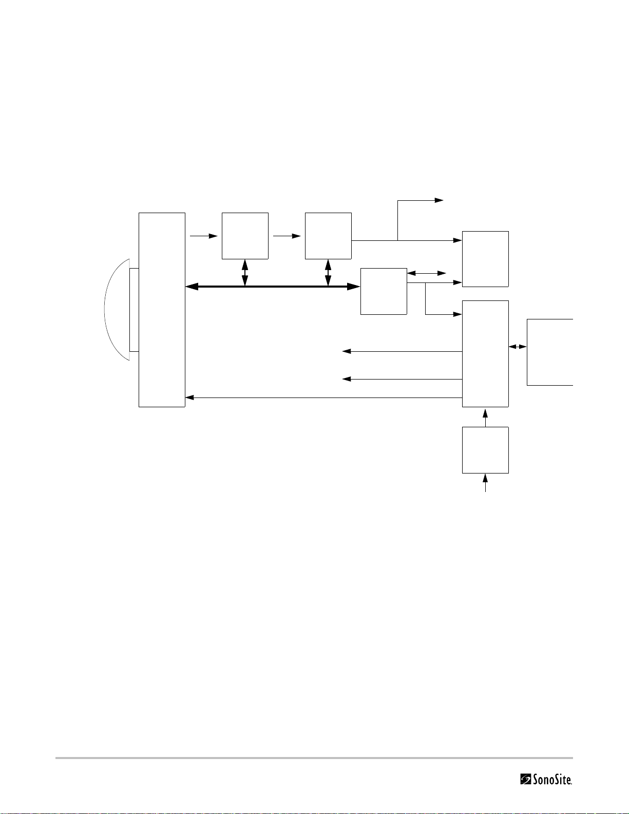
Figure 3.1 is a system block diagram that shows the relationship of the functional groups.
Acquisition
subsystem
Transd ucer
Processing
subsystem
Control Bus
External video to monitor,
VCR, printer
AQ BusRF Bus
Display
subsystem
Video
Control
subsystem
Display power
Logic power
User
interface
IrDA
Serial Bus
Power
subsystem
Battery
pack
assembly
Pulser voltage
Power
adapter
External power
Figure 3.1 SonoSite High-Resolution Ultrasound System (MicroMaxx) Block Diagram
The Transducer elements convert the pulser voltage to acoustic energy during the transmit portion of the
ultrasound acquisition cycle. The elements convert the acoustic echo to voltage in the receive portion of the
acquisition. The voltage developed on the transducer elements is sensed by the acquisition subsystem. The system
transducers have 64 to 128 elements.
The Acquisition Subsystem consists of the beamformer and interface to the transducer. The beamformer times
the transmit pulses to focus the acoustic beam. The beamformer amplifies the low-level echo signal and times the
receive information to focus the receive information. The system beamformers up to 64 transmit elements and 64
receive elements.
The Processing Subsystem includes capabilities for interfacing with the beamformer and performing high speed
processing. The processing subsystem demodulates, filters, detects, and compresses the signal supplied by the
beamformer into display information.
The Display Subsystem converts the detected ultrasound data into picture elements (pixels). The software user
interface graphics are combined with the ultrasound information and converted to a video stream. The external
video port supports NTSC and PAL format.
10 Chapter 3: System Overview
Page 17

The Control Subsystem consists of the central processing unit, program and video memory, permanent image
storage and retrieval memory, external communication interface ports, and connection to the user interface keys.
The control software includes the acoustic power and intensity software subsystem, power group monitors, and a
beamformer monitor. This software guarantees a level of patient safety by ensuring the system is operating within
acoustic power and intensity limits.
The User Interface Subsystem represents the software interface and form factor. The software interface is the
interaction between the user and the screen layout components. The form factor is the type of physical buttons,
location, and grouping of the buttons and the device size, shape, and weight. Dedicated controls are for high usage
activities and grouped according to the user workflow.
The Power Subsystem provides the system power and protects the hardware from destructive and/or unsafe
conditions by detecting failures in the system through hardware and software monitors. Detection of a fault results
in disabling of the pulser supply, and signaling of an error to the Control Group. The power subsystem includes the
battery pack and battery charging electronics.
Description of Operating Modes
2D Mode 2D mode is a two dimensional image of the amplitude of the echo signal. It is used for
location and measurement of anatomical structures and for spatial orientation during
operation of other modes. In 2D, a two-dimensional cross-section of a 3-dimensional soft
tissue structure such as the heart is displayed in real time. Ultrasound echoes of different
intensities are mapped to different gray scale or color values in the display. The outline of the
2D cross-section may be a rectangle, parallelogram, trapezoid, sector, or a full circle,
depending on the particular transducer used. 2D mode can be used in combination with any
other modes.
MMode “M Mode” is also known as “T-M mode” or “time-motion” mode. It is used primarily for
cardiac measurements such as valve timing and septal wall thickness when accurate timing
information is required.
Ultrasound echoes of different intensities are mapped to different gray scale values in a
scrolling display. M Mode displays time motion information of the ultrasound data derived
from a stationary beam. Depth is arranged along the vertical axis with time along the
horizontal axis. M Mode can be used alone but is normally used in conjunction with a 2D
image for spatial reference. The 2D image has a graphical line (M-line) superimposed on the
2D image indicating where the M Mode beam is located.
Color Power
Doppler
(CPD)
In CPD, a real-time two-dimensional cross-section of blood flow is displayed. The 2D
cross-section may be presented as a rectangle, parallelogram, trapezoid, sector, or a full
circle, depending on the particular transducer used.
The 2D cross-section is presented as a full color display, with various colors being used to
represent the power in blood flow echoes. Often, to provide spatial orientation, the full color
blood flow cross-section is overlaid on top of the gray scale cross-section of soft tissue
structure (2D echo). For each pixel in the overlay, the decision of whether to display CPD, gray
scale (echo) information or a blended combination is based on the relative strength of
echoes from the soft-tissue structures and from the red blood cells.
A high pass filter (wall filter) is used to remove the signals from stationary or slowly moving
structures. Tissue motion is discriminated from blood flow by assuming that blood is moving
faster than the surrounding tissue, although additional parameters may also be used to
enhance the discrimination. The power in the remaining signal after wall filtering may be
averaged over time (persistence) to present a steady state image of blood flow distribution.
Chapter 3: System Overview 11
Page 18

Continuous
Wave (CW)
Doppler
CW provides a real-time representation of blood flow and is displayed as a
velocity-versus-time sweeping output. Velocity (or frequency) is presented as the vertical
axis with time along the horizontal axis. The magnitude of the detected signal is represented
as different gray scale values.
CW Doppler mode provides the clinician with the ability to obtain blood flow velocities
focused about a user specified focal region. A continuous transmit waveform of ultrasound
energy with a known frequency is transmitted and focused by the System; on the receive
side, the transducer receive echoes are continuously amplified, focused about the focal
region and converted to a base band quadrature signal. The signal is analyzed by a
quadrature phase detector that establishes two receive channels to allow detection of flow
direction. These two channels are then analyzed by a fast complex Fourier transform (FFT)
circuit to establish the spectrum of frequencies present in the echoes. The data are displayed
as spectrum frequencies with respect to time.
CW can be used alone but is normally used in conjunction with a 2D image for spatial
reference. The 2D image has a graphical line (D-line) superimposed on the 2D image
indicating where the M-mode beam is located.
Pulsed Wave
(PW) Doppler
PW provides a real-time representation of blood flow and is displayed as a
velocity-versus-time sweeping output. Velocity (or frequency) is presented as the vertical
axis with time along the horizontal axis. The magnitude of the detected signal is represented
as different gray scale values. The ultrasound data is derived from a single area, the sample
volume, on a stationary beam.
PW Doppler mode provides the clinician with the ability to obtain blood flow velocities
about a spatial sample volume. A burst of ultrasound with a known spectrum is transmitted
by the System; on the receive side, the transducer receive echoes are amplified and range
gated at the appropriate depth. The signal is analyzed by a quadrature phase detector that
establishes two receive channels to allow detection of flow direction. These two channels are
then analyzed by a fast complex Fourier transform (FFT) circuit to establish the spectrum of
frequencies present in the echoes. The data are displayed as spectrum frequencies with
respect to time.
PW can be used alone but is normally used in conjunction with a 2D image for spatial
reference. The 2D image has a graphical line (D-line) superimposed on the 2D image
indicating where the M-mode beam is located. The sample volume position (depth) and size
are also indicated on the D-Line.
The Doppler functional processing platform is in Figure 3.2.
12 Chapter 3: System Overview
Page 19
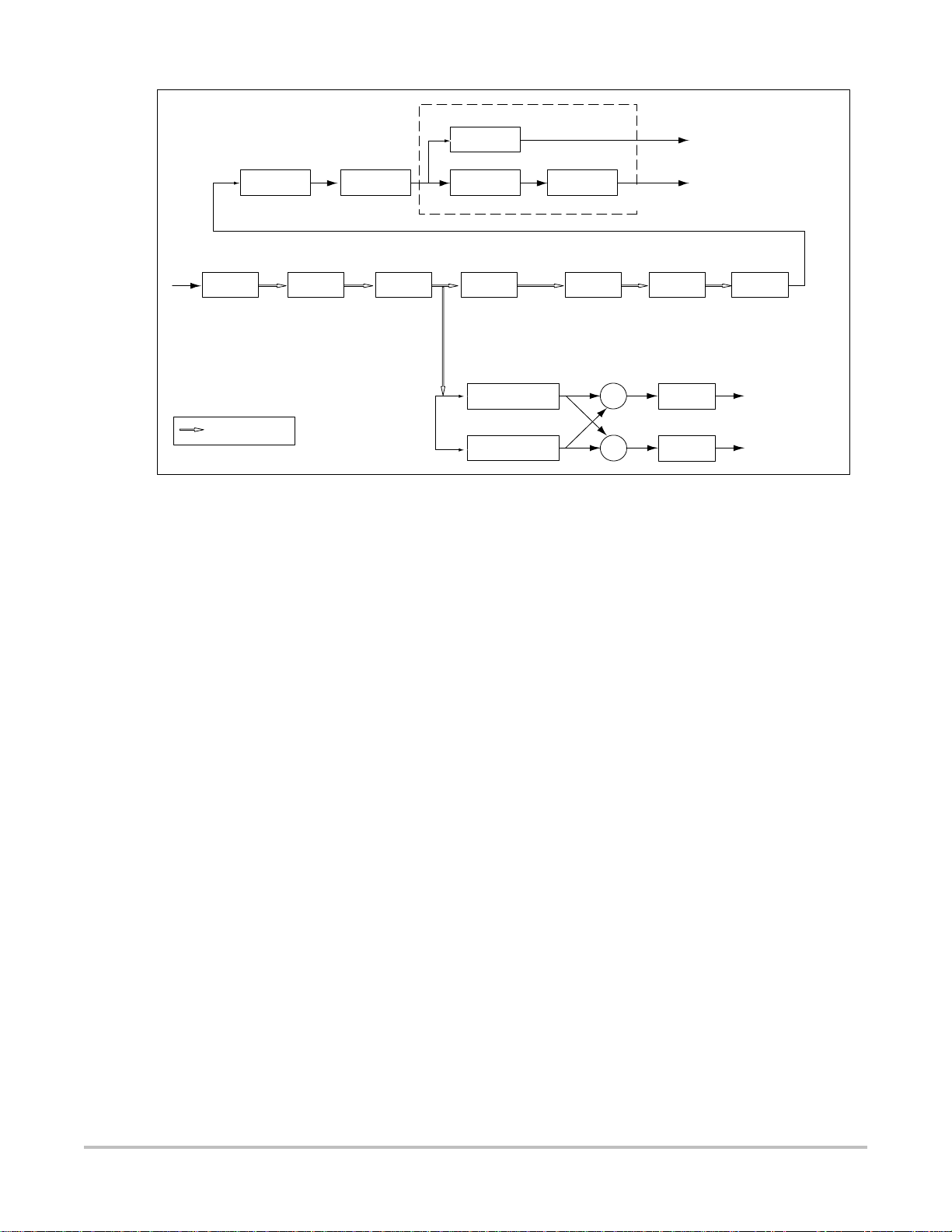
shifter
Delay
@ 1 kHz
DIS
interpolate
Display
+
_
Peak &
AVG
Temporal
Averaging
QBP WAF RES FFT MAG
QBP
RF (PW) or Quadrature
basband input (CW)
Indicates IQ pairs
128 samples
@ 50/100/200 Hz
Wall
filter
128 tap FIR 128 IQ pairs
CMP
Compress
Post
gain
mean
Baseline
shift
PRFPRF
Resample Window FFT |.|
I
Hilbert phase
Q
Figure 3.2 Doppler Processing Block Diagram
The Doppler processing platform can be partitioned into eight (8) blocks:
• Wall filter
• Resampler
• Hilbert phase shifter (stereo separator)
• Audio output
• Fast Fourier transformer (FFT)
• Magnitude estimation
• Temporal averaging
• Compression
128/192/256/384
samples per line
+
+
+
+
Back End
Audio
gain
2x16 bits @ PRF rate
Audio
gain
128 samples
@ 1 kHz
Audio Output
Wall Filter The wall filter is a high pass filter used to remove the clutter velocity information or wall
motion signal.
Resampler Time domain Doppler samples are transformed into spectral lines using a fast Fourier
transform (FFT) technique. The resampler module does the selection of a sample set used for
computing windowed FFTs. It thus interfaces the processing thread operating at the PRF rate
with the one that computes FFT on segments of data separated at the FFT rate.
Hilbert Phase
Shifter and
Audio Output
The gain adjusted IQ stream from the wall filter is processed by a Hilbert Transformer to shift
an in-phase component by 90 degrees to present the Doppler signal as stereo audio. The 90
degree phase shift in the in-phase component is accomplished by convolving it with the
Hilbert Transform impulse response. The quadrature component data stream does not
undergo any filtering other than a delay that matches the group delay of the in-phase
channel. This is followed by a stage that computes the sum and difference of in-phase and
quadrature components to produce stereo audio data.
Fast Fourier
Tra nsf orme r
This module applies a window function to the IQ sample set selected for spectral estimation
followed by the FFT. Radix 2 decimation-in-time FFT is performed using block-floating
scaling to retain maximum precision. The resulting output is later normalized during
magnitude computation.
Chapter 3: System Overview 13
Page 20

Magnitude
Estimation
This module combines real and imaginary components to estimate magnitude spectrum.
The magnitude of Doppler spectrum is calculated using “cordic approximation”, which is
done by estimating the complex magnitude by successive approximation. The vectors are
reflected into the first quadrant by taking the absolute value, then rotating them
sequentially by halved degrees.
Temporal
Averaging
Compression The compression module maps the input spectral magnitude values to display output
Spectral lines are produced by the FFT module at a constant rate. This module averages the
appropriate number of spectral lines to produce output lines at the desired display scroll
rate.
values.
Velocity Color Doppler (VCD)
In Velocity Color Doppler, a real-time, two-dimensional cross-section of blood flow is displayed. The 2D
cross-section may be presented as a rectangle, parallelogram, trapezoid, sector, or a full circle, depending on the
particular transducer used.
The 2D cross-section is presented as a full color display, with various colors being used to represent the velocity,
both positive and negative, of the blood flow echoes. Often, to provide spatial orientation, the full color blood flow
cross-section is overlaid on top of the gray scale cross-section of soft tissue structure (2D echo). For each pixel in
the overlay, the decision of whether to display VCD, gray scale (echo) information or a blended combination is
based on the relative strength of echoes from the soft-tissue structures and from the red blood cells.
A high pass filter (wall filter) is used to remove the signals from stationary or slowly moving structures. Tissue
motion is discriminated from blood flow by assuming that blood is moving faster than the surrounding tissue,
although additional parameters may also be used to enhance the discrimination. The remaining signal after wall
filtering may be averaged over time (persistence) to present a steady state image of blood flow distribution.
Variance information may also be displayed to provide information when large variance is observed in the velocity
information.
14 Chapter 3: System Overview
Page 21

Additional System Feature Performances
Broadband Imaging This ultrasound acquisition system uses high resolution uses broadband technology
in the transmit pulsers, transducer, and receivers. The receive path can capture and
process signals over a wide spectrum, from below 2.0 MHz to beyond 10 MHz. For
each application, the transmit pulse is designed to produce an appropriate
bandwidth. For example, in 2D grayscale imaging, a wide band pulse is used to
support good axial resolution. For Doppler modes, a narrower band pulse is used,
which improves the spectral resolution of the detected Doppler signal.
In addition to transmit pulse control, programmable digital signal processing is used
in the receive path to further refine the bandwidth used to produce the final image.
Digital filters are applied to the digitized received signal to limit and shape the
spectral bandwidth used to generate the displayed output.
Tissue Specific
Imaging
Biopsy Guidance The System is capable of displaying a pair of biopsy guidelines that represent the
Measurement and
Calculation
Capabilities
Continuous Wave
Doppler Audio
Output
In this feature, parameters for signal and image processing are optimized to
maximize the image quality or to obtain the best compromise of resolution and
penetration for different specific clinical applications. These parameters include: the
order of received filters, the bandwidth, the dynamic range, the compression curve,
the gain setting and parameters for compounding frequency band, etc. For example,
different system parameter setups are used for abdominal or peritoneal scanning.
This feature is for ease of use for the operator by automatically setting up system
control parameters rather than manually adjusting settings for best performance.
anticipated path of the biopsy needle. The image of an anatomical target, biopsy
guidelines, a scan plane marker, and a biopsy needle are displayed on the monitor to
assist in guiding the biopsy needle to the target. The system also provides needle
guidance for vascular access procedures. Additional information regarding this
feature can be found in the biopsy user guides.
The System offers a variety of measurements and calculations, specific to exam type
and transducer. A listing of the volume, cardiac, Doppler and obstetrical calculations
and measurements that may be made is provided in the User Guide, in the chapter
Measurements and Calculations, and author reference in provided the chapter
References.
Measurement accuracy is discussed the Reference chapter of the User Guide.
The system provides for audio output of the CW velocity information. This can be
presented as stereo information, with flow moving towards the transducer on one
channel and flow away on the other, or as a monaural output with the single audio
output representing the summation of the flow directions.
Pulsed Wave Doppler
Audio Output
Electrocardiograph
(ECG) Display
Chapter 3: System Overview 15
The System provides for audio output of the PW velocity information. This can be
presented as stereo information, with flow moving towards the transducer on one
channel and flow away on the other, or as a mono output with the single audio
output representing the summation of the flow directions.
ECG is provided to measure the electrical signal generated by the heart. A three lead
interface: Right Arm (RA), Left Arm (LA) and Left Leg (LL), is provided on the System.
The ECG signal is displayed as an amplitude-versus-time sweeping output.
Amplitude is presented on the vertical axis with time along the horizontal axis.
Page 22
ECG Module
The ECG module allows a representation of the heart electrical activity to be displayed in real time with ultrasound
images acquired and displayed on the System video display.
The ECG module interfaces to the patient through three (3) ECG leads: Right Arm ECG lead (RA), Left Arm ECG lead
(LA), and Left Leg ECG lead (LL). The ECG received signal from the ECG electrodes are isolated, amplified, and
filtered by the ECG module before it is sent to the System for further processing and display.
The ECG module and cable are an integrated assembly. The module receives power from the System. Patient
isolation is provided by the ECG module, allowing the connection and signals to the System to be System-ground
referenced. The isolation between the patient and the System meets the requirements of IEC 601-1 for Type BF
equipment.
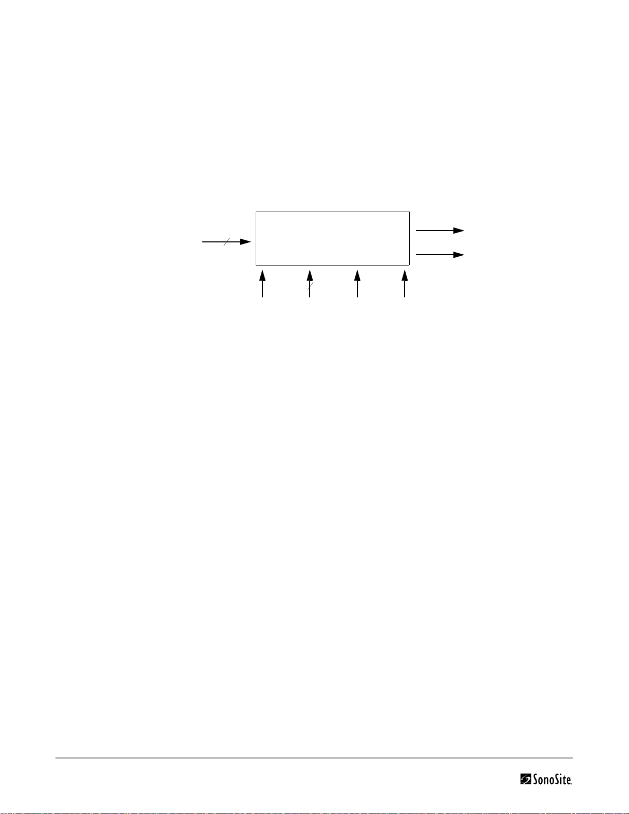
The top-level functional block diagram is shown in Figure 3.3.
To pa tient
ECG leads
3
Analog out
ECG Module
Sense
2
VPWR I2C BUS FLTR_CLK PWR_CLK
From system
To system
Figure 3.3 ECG Module Block Diagram
The ECG module can be partitioned into six (6) different blocks:
• Pre-amplifier block
• Isolation block
• High pass filter block
• Variable amplifier block
• Low pass filter block
•Power supplies block
Pre-Amplifier The pre-amplifier block provides the interface to the ECG leads. It provides high levels of
common mode rejection and the initial gain for the ECG signal. This block also provides a
high pass function to eliminate any large direct current (DC) offsets to allow a
moderately high gain to be set before isolation, allowing the front end to set the input
equivalent noise of the electrical ECG signal path.
Isolation The isolation block provides voltage isolation for the analog signal. The voltage isolation
between the patient and the system meets the requirement of the ANSI/AAMI EC13
specification.
High Pass Filter The high pass filter block removes the low frequency components and biases the opt
coupler output for the received ECG signal.
Variable
Amplifier
The variable amplifier blocks provide additional gain for the received ECG signal. The
blocks are used to boost the signal. There are three gain settings for the variable
amplifier, controlled by the system through the control bus.
16 Chapter 3: System Overview
Page 23

Low Pass Filter The low pass filter block removes the high frequency component from the received ECG
signal. It is used to limit the signal to the frequency range of interest and provide
rejection of 50/60 Hz signal content.
Power Supplies The power supply block receives voltage from the system power supply. It also generates
isolation power supplies for the pre-amplifier and isolation blocks. It can be disabled to
reduce power consumption while the module is not in use.
Digital Storage
and Transfer of
Images and Data
The System stores images and data internally for review. Data and images may be
recalled from storage for review on the system. Images or data displayed on the screen
may be captured on an external video printer or video recorder, or be transferred to a
personal computer.
DICOM
The system features Digital Imaging and Communications (DICOM) capability to provide the acceptance, transfer,
display, storage, and digital processing of single ultrasound images as well as loops of Ultrasound images.
IMT
The system includes the ability to measure the intima-media thickness (IMT) of the carotid artery using digital
ultrasound images. The intima is that region of the arterial wall from and including the endothelial surface at the
lumen to the luminal margin of the media. The media layer extends from the intima to the adventitia of the vessel
wall. The adventitia is normally quite echogenic on ultrasound images when compared to the media. The IMT
measurement of the carotid artery may be used adjunctively with other medical data obtained by a physician to
help assess the cardiovascular health of a patient.
System Specifications
This section contains system and accessory specifications and agency approvals. The specifications for
recommended peripherals can be found in the manufacturers’ instructions.
System Dimensions
Length: 11.8 in. (29.97 cm)
Width: 10.8 in. (27.43 cm)
Height: 3.1 in. (7.87 cm)
Weight: 8.5 lbs. (3.9 kg) with the C60e transducer and battery installed
Display Dimensions
Length: 8.4 in. (21.34 cm)
Height: 6.3 in. (16 cm)
Diagonal: 10.4 in. (26.4 cm)
Transducers
C60e/5-2 MHz 60 mm curved array (5 ft./1.5 m)
HFL38/13-6 MHz 25 mm linear array (5.5 ft./1.7 m)
ICT/8-5 MHz 11 mm intracavitary array (5 ft./1.5 m)
L38e/10-5 MHz 38 mm linear array (5.5 ft./1.7 m)
P17/5-1 MHz 17 mm phased array (6 ft./1.8 m)
TEE/8-3 MHz phased array (11.15 ft./3.4 m)
Chapter 3: System Overview 17
Page 24

Imaging Modes
2D (256 gray shades)
Color power Doppler (CPD) (256 colors)
Color Doppler (Color) (256 colors)
MMode
Pulsed wave (PW) Doppler
Continuous Wave (CW) Doppler
Tissue Harmonic Imaging
Image Storage
The number of images saved to the CompactFlash card vary depending on the card storage capacity.
Cine buffer
Accessories
Hardware, Software, and Documentation
AIUM Ultrasound Medical Safety Guidance Document
Battery
Biopsy Guide
Carry case
External display
Guidance on the interpretation of TI and MI to be used to inform the operator, Annex HH, BS EN 60601-2-37
Mobile Docking System Lite (MDS Lite)
Mobile Docking System (MDS)
Mini-Dock
Power supply
Quick Reference Guide
SiteLink Image Manager 3.0
SonoCalc IMT
System User Guide
Triple Transducer Connect
Ultrasound gel
Cables
See the MicroMaxx Ultrasound System User Guide, MDS User Guide, and the MDS Lite User Guide for information on
cables.
18 Chapter 3: System Overview
Page 25

Peripherals
See the manufacturer’s specifications for the following peripherals.
Medical Grade
Black-and-white printer
Recommended sources for printer paper: Contact Sony at 1-800-686-7669 or
www.sony.com/professional to order supplies or to obtain the name and number of the local distributor.
Color printer
Video cassette recorder
Non-Medical Grade
Kensington Security Cable
Temperature, Pressure, and Humidity Limits
Note: The temperature, pressure, and humidity limits apply only to the ultrasound system and transducers.
Operating Limits: System
• 10–40°C (50–104°F), 15–95% R.H.
• 700 to 1060hPa (0.7 to 1.05 ATM)
Shipping/Storage Limits: System without Battery
• -35–65°C (-31–149°F), 15–95% R.H.
• 500 to 1060hPa (0.5 to 1.05 ATM)
Operating Limits: Battery
• 10–40°C (50–104°F), 15–95% R.H.
Shipping/Storage Limits: Battery
• -20–60°C (-4–140°F), 0–95% R.H.*
• 500 to 1060hPa (0.5 to 1.05 ATM)
* For storage longer than 30 days, store at or below room temperature.
Operating Limits: Transducer
• 10–40°C (50–104°F), 15–95% R.H.
Shipping/Storage Limits: Transducer
• -35–65°C (-31–149°F), 15–95% R.H.
Electrical
Power Supply Input: 100-240 VAC, 50/60 Hz, 1.2 A Max @ 100 VAC.
Power Supply Output (system on): (1) 15 VDC, 2.7A Max (system)
(2) 12.6 VDC, 0.8A Max (battery charging)
Power Supply Output (system off): (1) 15 VDC, 2.0A Max (system)
(2) 12.6 VDC, 1.8A Max (battery charging)
Combined output not exceeding 52W.
Battery
6-cell, 11.25 VDC, 4.4 amp-hours, rechargeable lithium ion battery pack.
Run time is 2 hours or more, depending on imaging mode and display brightness.
Chapter 3: System Overview 19
Page 26

Electromechanical Safety Standards
EN 60601-1:1997, European Norm, Medical Electrical Equipment–Part 1. General Requirements for Safety.
EN 60601-1-1:2001, European Norm, Medical Electrical Equipment–Part 1. General Requirements for
Safety–Section 1-1. Collateral Standard. Safety Requirements for Medical Electrical Systems.
EN 60601-2-37:2001, European Norm, Particular requirements for the safety of ultrasonic medical diagnostic and
monitoring equipment.
CAN/CSA C22.2, No. 601.1-M90:1990, Canadian Standards Association, Medical Electrical Equipment–Part 1.
General Requirements for Safety.
CEI/IEC 61157:1992, International Electrotechnical Commission, Requirements for the Declaration of the Acoustic
Output of Medical Diagnostic Ultrasonic Equipment.
UL 60601-1:2003, Underwriters Laboratories, Medical Electrical Equipment-Part 1: General Requirements for
Safety.
EMC Standards Classification
EN 60601-1-2:2001, European Norm, Medical Electrical Equipment. General Requirements for Safety-Collateral
Standard. Electromagnetic Compatibility. Requirements and Tests.
CISPR11:2004, International Electrotechnical Commission, International Special Committee on Radio Interference.
Industrial, Scientific, and Medical (ISM) Radio-Frequency Equipment Electromagnetic Disturbance
Characteristics-Limits and Methods of Measurement.
The Classification for the SonoSite system, SiteStand, accessories, and peripherals when configured together is:
Group 1, Class A.
Airborne Equipment Standards
RTCA/DO160D:1997, Radio Technical Commission for Aeronautics, Environmental Conditions and Test Procedures
for Airborne Equipment, Section 21.0 Emission of Radio Frequency Energy, Category B.
DICOM Standard
NEMA PS 3.15: 2000, Digital Imaging and Communications in Medicine (DICOM)-Part 15: Security Profiles.
HIPAA Standard
The Health Insurance and Portability and Accountability Act, Pub.L. No. 104-191 (1996).
45 CFR 160, General Administrative Requirements.
45 CFR 164, Security and Privacy.
20 Chapter 3: System Overview
Page 27
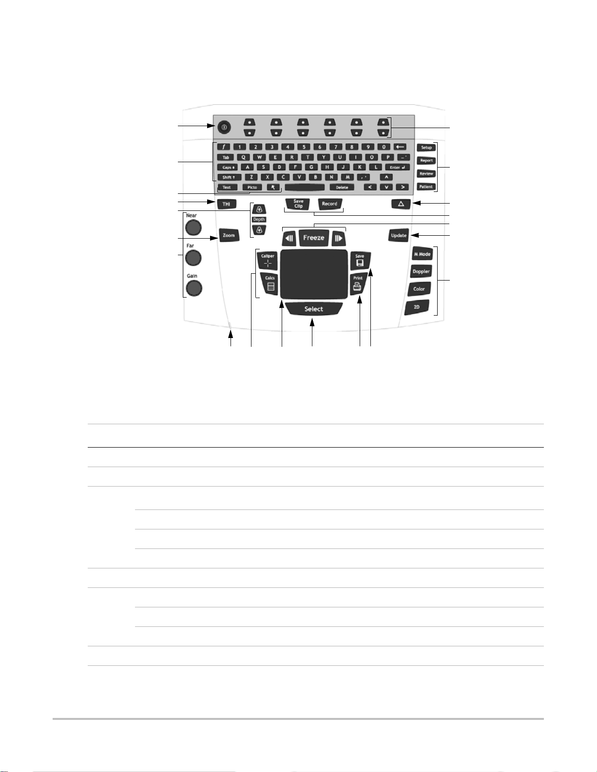
Chapter 4: Setup and Operation
System Controls
1
2
3
4
5
6
7
Figure 4.1 System Controls
8 9 11 12 13
10
14
15
16
17
18
19
20
Table 4.1: System Controls
Number System Control Description
1 Power Turns system on and off.
2 Alphanumeric Use to enter text and numbers.
3
Annotation
Text Turns the keyboard on and off for text entry.
Picto Turns the pictographs/pictograph marker on and off.
Arrow Displays an arrow that can be moved and rotated within the image area.
4 THI Turns Tissue Harmonic Imaging on and off.
5 Depth Adjusts the imaging depth for 2D.
Depth Up Decreases imaging depth.
Depth Down Increases imaging depth.
6 Zoom Magnifies image 2x.
Chapter 4: Setup and Operation 21
Page 28

Table 4.1: System Controls (Continued)
Number System Control Description
7 Near Adjusts the gain applied to the near field of the image.
Far Adjusts the gain applied to the far field of the image.
Gain Adjusts the overall gain applied to the entire image.
8 AC power
indicator
A steady green light indicates AC power is connected. A flashing green light
indicates the system is in sleep mode.
9 Caliper/Calcs Caliper activates a measurement caliper on the screen.
Calcs turns the calculation menu on and off.
10 Touchpad Use to select, adjust, and move objects on the screen.
11 Select Use to switch between frozen images in duplex and dual screens. color and
Doppler menus, calipers for measurement (calipers), pictograph marker
position/angle (picto), arrow position/orientation (arrow).
12 Print Prints the active image to the printer.
13 Save Saves an image to the CompactFlash card.
Saves an image to the CompactFlash card and saves measurements/calculation
to the report when configured in system setup.
14 Remappable
controls
15
Forms
Controls features on the context menu which are adjusted based on the system
state.
Setup Access to the system settings.
Report Access to the patient report.
Review Access to the patient list and saved patient images, and archive functions.
Patient Access to patient information.
16
(Delta key)
Use as a shortcut to existing functionality in the system.
17 Save clip Saves a clip to the CompactFlash card.
Record Turns DVD/VCR record on and off.
18 Freeze Stops the live imaging and displays a frozen image.
Cine
(back/forward)
Review images stored in the cine buffer; back/forward through last-in, first-out
sequence. All mode images can be stored and reviewed in the cine buffer.
19 Update Toggles between dual and duplex screens and image modes in M Mode and
Doppler, e.g., between 2D Doppler sample line and Doppler spectral trace.
22 Chapter 4: Setup and Operation
Page 29

Table 4.1: System Controls (Continued)
Number System Control Description
20
Modes
M Mode Turns M Mode on and toggles between M Mode sample line and the M Mode
Doppler Turns Doppler on and toggles between Doppler sample line and the Doppler
Color Turns CPD/Color on and off.
2D Turns 2D on.
System Components
The SonoSite system components are identified in “About the System” on page 2.
Setup
System setup is used to customize the system. Press the Setup key to access and set up the following system
functions:
Administration Configure system to protect patient data by requiring users to log on and
trace.
trace.
enter passwords.
Audio, Battery Configure for type of Audio alert, Sleep delay, and Power delay.
Connectivity Configure Printer, Video mode, Serial Port, and Transfer Mode: DICOM or
SiteLink.
(DICOM and SiteLink are optional features.)
Date and Time Configure Date and Time functions.
Delta Key, F Keys Configure existing system functionality as a shortcut and create predefined
labels for images.
Display Information Configure information displayed on image: patient information, mode data,
and system status data.
IMT calculations Configure the IMT calculation menu and presets.
OB Calculations Select OB calculation authors.
OB Custom Measurements Configure system for user defined measurements.
(OB Custom Measurements are an optional feature.)
Presets Configure Preset functions: Doppler Scale, Duplex, Live Trace, Thermal
Index, Save Key, and Dynamic Range.
System Information Displays system hardware and software versions.
Chapter 4: Setup and Operation 23
Page 30
Setup Security Settings
Security Setup
WAR NIN G:
SonoSite provides a comprehensive set of tools on the system that allows its customers to meet the applicable
security requirements listed in the HIPAA standard. SonoSite's customers are ultimately responsible for ensuring
the security and protection of all electronic protected health information collected, stored, reviewed, and
transmitted on the system.
Health care providers who maintain or transmit health information are required by the Health
Insurance Portability and Accountability Act (HIPAA) of 1996 and the European Union Data
Protection Directive (95/46/EC) to implement appropriate procedures: to ensure the integrity and
confidentiality of information; to protect against any reasonably anticipated threats or hazards to
the security or integrity of the information or unauthorized uses or disclosures of the information.
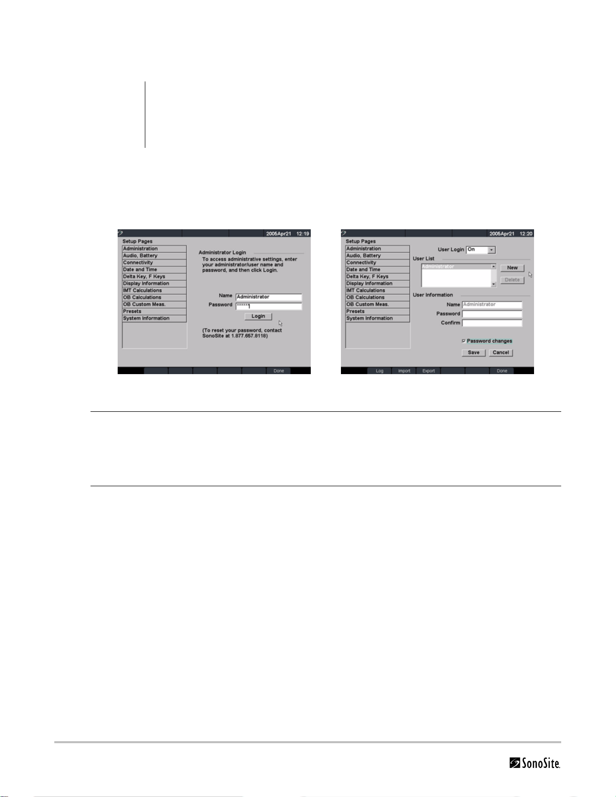
Figure 5 Setup Screens: Administration and Administrator Information
Administrator Login 1 Press the Setup key.
2 Select Administration.
3 In Administrator Login, type Administrator in the Name field.
4 Call SonoSite for the password (1-877-657-8118).
5 Select Login.
Change Administrator
Password
1 In User Information, enter your new password in the Password field.
2 Enter the password again in the Confirm field.
To ensure passwords are secure, it is recommended that passwords contain
characters from the following categories:
• Upper case characters: A-Z
• Lower case characters: a-z
• Numbers: 0-9
Note: The password is case-sensitive.
3 In Password changes, click on the check box to allow users access to change
their password or leave unchecked to restrict access. (Optional)
4 Select Save.
24 Chapter 4: Setup and Operation
Page 31

User Login Setting 1 In the User Login list, select On or Off.
User Setup
Figure 6 Setup Screen: User List Information
• Selecting On restricts access to the system and requires the user to enter a
user name and password.
• Selecting Off allows access to the system and does not require the user to
enter a user name and password.
2 After making changes in the Administration setup, reboot the system to log off
as administrator.
Add New User 1 Select New.
2 In User Information, enter information in Name, Password, and Confirm fields.
To ensure passwords are secure, it is recommended that passwords contain
characters from the following categories:
• Upper case characters: A-Z
• Lower case characters: a-z
• Numbers: 0-9
Note: The name and password are case-sensitive.
3 In Sonographer, enter the user’s initials to display the information in the patient
header and the sonographer field in the Patient Information form. (Optional)
4 In Administration Access, click the check box to allow users access to all
administration privileges or leave unchecked to restrict access. (Optional)
5 Select Save.
Modify User Information 1 In the User List, select desired user name.
2 Enter the new name.
3 Enter the new password and confirm.
4 Select Save.
Any change to the user name replaces the old name.
Delete User 1 In the User List, select the desired user name.
2 Select Delete.
A dialog is displayed.
3 Select Yes to delete or No to cancel.
Change User Password 1 In the User List, select the desired user name.
2 Enter the new password and confirm.
3 Select Save.
Done Select Done from the on-screen menu to return to live imaging.
Chapter 4: Setup and Operation 25
Page 32

Export or Import User Accounts
Note: Export and import are used to configure multiple systems and to back up user account information.
Export User Account 1 Insert the CompactFlash card in the back slot of the system. See “Installing and
Import User Account 1 Insert the CompactFlash card in the back slot of the system. See “Installing and
Reset Select Reset from the on-screen menu to return settings for this setup page to
Removing the CompactFlash Card” on page 39.
2 Press the Setup key.
3 Select Administration.
4 Select Export from the on-screen menu.
All user names and passwords are copied to the CompactFlash card.
5 Remove the CompactFlash card.
Removing the CompactFlash Card” on page 39.
2 Press the Setup key.
3 Select Administration.
4 Select Import from the on-screen menu.
A dialog box is displayed.
5 After all user names and passwords are imported, the system restarts.
Note: All user names and passwords currently on the system are replaced with the
imported data.
factory default.
Export and Clear Event Log
The Event Log collects errors and events and can be exported to a CompactFlash card and read by a CompactFlash
reader.
Figure 7 Event Log
Event Log 1 Press the Setup key.
2 Select Administration.
3 Select Log from the on-screen menu.
The Event Log is displayed.
4 Select Back to return to the previous menu.
26 Chapter 4: Setup and Operation
Page 33

Export Event Log Note: The Event log and the DICOM network log have the same filename (log.txt). When
Clear Event Log 1 Select Clear from the on-screen menu.
Login to System as User
you export either one to the same CompactFlash card, it will overwrite the existing
log.txt file.
1 Insert the CompactFlash card in the back slot of the system.
2 Select Log and then Export from the on-screen menu.
3 View the files on a CompactFlash reader.
The log is a text file that can be opened by a text file application, e.g., Microsoft
Word or Notepad. The log file is named log.txt.
2 Select Yes to delete or No to cancel.
Figure 8 User Login and Change Password
Note: User Login is displayed when system access is turned on.
User Login In User Login, enter Name and Password and click OK.
Guest Login In User Login, select Guest.
In Guest mode the user is able to scan but is restricted from accessing system setup and patient
information.
Change
Password
1 In User Login, select Password.
2 Enter your old password, new password, confirm the new password and then click OK.
To ensure passwords are secure, it is recommended that passwords contain characters from
the following categories:
• Upper case characters: A-Z
• Lower case characters: a-z
• Numbers: 0-9
Note: The password is case-sensitive.
Chapter 4: Setup and Operation 27
Page 34

Audio and Battery
Figure 9 Setup Screen: Audio, Battery
Key Click 1 Press the Setup key.
Beep Alert 1 Press the Setup key.
2 Select Audio, Battery.
3 In the Key click list, select On or Off.
2 Select Audio, Battery.
3 In the Beep alert list, select On or Off.
Sleep Delay 1 Press the Setup key.
2 Select Audio, Battery.
3 In the Sleep delay list, select Off, 5, or 10 minutes.
Power Delay 1 Press the Setup key.
2 Select Audio, Battery.
3 In the Power delay list, select Off, 15, or 30 minutes.
Reset Select Reset from the on-screen menu to return settings for this setup page to
factory default.
28 Chapter 4: Setup and Operation
Page 35

Connectivity
Figure 10 Setup Screens: Connectivity and Ethernet
Printer 1 Press the Setup key.
Video Mode 1 Press the Setup key.
2 Select Connectivity.
3 In the Printer list, select the desired printer from the list of recommended
printers.
2 Select Connectivity.
3 In the Video mode list, select NTSC or PAL for the desired mini-dock video
output.
Serial Port 1 Press the Setup key.
2 Select Connectivity.
3 In the Serial Port list, select VCR, DVD, or Computer (PC).
4 Restart the system to activate VCR or DVD connectivity.
5 Attach a serial cable (RS-232) to the serial port from the mini-dock/MDS to the
VCR, DVD, or PC.
Note: If PC is selected, the system allows report data to be sent as ASCII text from the
system to a PC. Special third party software must be on the PC to acquire, view, or
format the data into a report. Check the compatibility of your software with SonoSite
technical support.
Transfer Mode 1 Press the Setup key.
2 Select Connectivity.
3 In the Transfer Mode list, select DICOM or SiteLink.
After changing connectivity, a dialog box is displayed to restart the system.
Note: The settings for SiteLink Image Manager and system configurations must
correspond. See the SiteLink Image Manger 3.0 User Guide.
Ethernet Connectivity 1 Press the Setup key.
2 Select Connectivity.
3 In the Transfer Mode list, select SiteLink.
After changing connectivity, a dialog box is displayed to restart the system.
Chapter 4: Setup and Operation 29
Page 36

Ethernet Setup 1 Press the Setup key.
Reset Select Reset from the on-screen menu to return settings for this setup page to
Date and Time
2 Select Connectivity.
3 Select Ethernet Setup.
4 Enter information in the following fields: (see DICOM chapter for definition of
terms)
•Host Name
•IP Address
•Subnet Mask
•Default Gateway
• Alternate Gateway
5 In the Network Speed list, select from the list.
6 Select Save.
factory default.
Figure 11 Setup Screen: Date and Time
WAR NIN G:
Date 1 Press the Setup key.
Time 1 Press the Setup key.
Reset Select Reset from the on-screen menu to return settings for this setup page to
An accurate date and time are critical for accurate obstetrics calculations. Verify that the date and
time are accurate before each use of the system. The system does not automatically adjust for
daylight savings time changes.
2 Select Date and Time.
3 In the Date field, enter the current date (year, month, and day).
2 Select Date and Time.
3 In the Time field, enter the current time in 24 hour format (hours and minutes).
factory default.
30 Chapter 4: Setup and Operation
Page 37

Delta Key and F Keys
Figure 12 Setup Screen: Delta Key, F Keys
Delta Key 1 Press the Setup key.
F Keys 1 Press the Setup key.
2 Select Delta Key, F Keys.
3 Select desired functionality for the Delta key.
The Delta key will now control this function.
2 Select Delta Key, F Keys.
3 Type desired text. Use the Backspace key or Delete key to correct mistakes.
Reset Select Reset from the on-screen menu to return settings for this setup page to
Display Information
Figure 13 Setup Screen: Display Information
Patient Header 1 Press the Setup key.
factory default.
2 Select Display Information.
3 Select the desired check boxes to display desired information in the patient
header.
Mode Data 1 Press the Setup key.
2 Select Display Information.
3 Select the desired check boxes to display imaging information on the screen.
Chapter 4: Setup and Operation 31
Page 38

System Status 1 Press the Setup key.
Reset Select Reset from the on-screen menu to return settings for this setup page to
IMT Calculations
Figure 14 Setup Screen: IMT Calculations
2 Select Display Information.
3 Select the desired check boxes to display the system status on the screen.
factory default.
IMT Calculations 1 Press the Setup key.
2 Select IMT Calculations.
3 In the IMT calculations list, select the desired labels.
• Selecting a label places the measurement on the Calculation menu and
within the report.
• Selecting None removes a label.
Reset Select Reset from the on-screen menu to return settings for this setup page to
factory default.
32 Chapter 4: Setup and Operation
Page 39

OB Calculations Authors
Figure 15 Setup Screen: OB Calculations
Gestational Age
Growth Analysis
More... More... displays the list of user defined custom measurements and allows you to
Export 1 Insert a blank CompactFlash card in the back slot of the system.
Import 1 Insert the CompactFlash card in the back slot of the system.
1 Press the Setup key.
2 Select OB Calculations.
3 In Gestational Age or Growth Analysis lists, select the desired OB authors.
Selecting an author places the measurement on the calculation menu and
selecting None removes the measurement from the calculation menu.
associate a custom table for the custom measurement. This is only available when a
user defined custom table has been created for the custom measurement.
2 Press the Setup key.
3 Select OB Calculations.
4 Select Export from the on-screen menu.
All user defined tables and measurements are copied to the CompactFlash card.
2 Press the Setup key.
3 Select OB Calculations.
4 Select Import from the on-screen menu.
5 After all user defined tables and measurements are imported, the system
restarts.
Note: All user defined tables and measurements currently on the system are
replaced with imported data.
6 Select Done from the on-screen menu to return to live imaging.
Tabl es .. . Tables... displays system OB tables or is used to create custom OB tables. See “OB
Custom Tables” on page 35.
Reset Select Reset from the on-screen menu to return settings for this setup page to
factory default.
Chapter 4: Setup and Operation 33
Page 40

OB Custom Measurements
Figure 16 Setup Screen: OB Custom Measurements
OB Custom
Measurements
Delete OB Custom
Measurement
Tabl es .. . Select Tables... from the on-screen menu to create Gestational Age tables for a
1 Press the Setup key.
2 Select OB Custom Meas.
3 Select New.
4 In the Name field, enter a unique name.
5 In the Type list, select the desired measurement type.
6 Select Save.
The new measurement is displayed in the calculations menu and the OB report.
Up to five custom measurements may be saved.
1 Press the Setup key.
2 Select OB Custom Meas.
3 In the Custom Measurements list, highlight the last measurement.
4 Select Delete Last.
Note: If associated tables and report data exist for the measurement, they will be
removed from the system.
custom OB measurement. See “OB Custom Tables”.
34 Chapter 4: Setup and Operation
Page 41

OB Custom Tables
Figure 17 Setup Screen: OB Custom Table
Age Table Measurements: The system provides gestational age measurements by selected authors for the age
table measurements listed in Tab le 4.2 .
Growth Analysis Table Measurements: The system provides growth graphs or curves for the growth table
measurements listed in Tab le 4.2 .
Table 4.2: OB Custom Table Measurements
Age Table Measurements GS, CRL, BPD, OFD, HC, TTD, AC, FTA, FL, 5 additional custom
measurement labels
Growth Analysis Table Measurements BPD, HC, AC, FL, EFW
WAR NIN G:
View OB Tables 1 Press the Setup key.
Create New OB Custom
Tabl es
Prior to use, verify custom table data entries are correct. The system does not confirm the
accuracy of the custom table data entered by the user.
2 Select OB Custom Meas. or OB Calculations.
3 Select Tables... from the on-screen menu.
4 Select the desired table (Age or Growth) and measurement/author.
1 Press the Setup key.
2 Select OB Custom Meas. or OB Calculations.
3 Select Tables... from the on-screen menu.
4 Select the desired table (Age or Growth).
5 In the measurement list, select the desired measurement for the custom table.
6 Select New from the on-screen menu.
7 In the Author field, enter a unique name.
8 Enter the data.
9 Select Save from the on-screen menu.
Two custom tables may be created for each OB measurement.
Note: To display the measurement for the custom table in the calculation menu,
see “OB Calculations Authors” on page 33 and select More...
Note: Growth analysis tables cannot be created for custom OB measurements.
Chapter 4: Setup and Operation 35
Page 42

Presets
Edit OB Custom Tables 1 Press the Setup key.
2 Select OB Custom Meas. or OB Calculations.
3 Select Tables... from the on-screen menu.
4 Select the desired custom OB table.
5 Select Edit and enter data and then select Save from the on-screen menu.
Delete OB Custom Tables 1 Press the Setup key.
2 Select OB Custom Meas. or OB Calculations.
3 Select Tables... from the on-screen menu.
4 Select the desired custom OB table.
5 Select Delete from the on-screen menu to remove the custom table from the
system.
Figure 18 Setup Screen: Presets
Doppler Scale 1 Press the Setup key.
2 Select Presets.
3 In the Doppler Scale list, select cm/s or kHz.
Duplex 1 Press the Setup key.
2 Select Presets.
3 In the Duplex list, select desired image display.
• Full 2D, Full Trace
• 1/3 2D, 2/3 Trace
• 1/2 2D, 1/2 Trace
Live Trace 1 Press the Setup key.
2 Select Presets.
3 In the Live Trace list, select Peak or Mean.
Thermal Index 1 Press the Setup key.
2 Select Presets.
3 In the Thermal Index list, select TIS, TIB, or TIC.
36 Chapter 4: Setup and Operation
Page 43

Save Key 1 Press the Setup key.
Dynamic Range 1 Select the desired exam type.
Reset Select Reset from the on-screen menu to return settings for this setup page to
System Information
2 Select Presets.
3 In the Save key list, select Image Only or Image/Calcs to designate the function
of the Save key.
• Selecting Image Only allows the Save key to save the image to the
CompactFlash card.
• Selecting Image/Calcs allows the Save Key to save the image to the
CompactFlash card and to save the current calculation to the report.
2 Press the Setup key.
3 Select Presets.
4 Select the desired dynamic range setting (-3, -2, -1, 0, +1, +2, +3).
Note: Negative numbers show higher contrast images and positive numbers show
lower contrast images.
factory default.
Figure 19 Setup Screen: System Information
System Information 1 Press the Setup key.
2 Select System Information from the on-screen menu.
Note: To install a license key see “Install License Key” on page 47.
Change to Default
Settings
1 Turn the system off.
2 Connect the system to AC power. See “Operate System Using AC power” on
page 40.
3 Simultaneously press and release 1 and the Power key.
The system beeps several times and then the image display appears with all
default settings.
Note: Default settings cannot be changed by the user. Default settings are set at
the factory.
Chapter 4: Setup and Operation 37
Page 44

To uc hp a d
The touchpad is used to select, adjust, and move objects on the screen. For example, it controls the caliper position,
CPD/Color box position, floating cursor, and more.
Note: The arrow keys control much of the same functionality as the touchpad.
Accessories
For information about accessories and other SonoSite products, refer to the user guide for each product.
Preparing the System for Operation
Installing and Removing the Battery
Caution:
The battery comprises six lithium-ion cells plus electronics, a temperature sensor, and battery contacts.
If the battery is being installed for the first time, it will need to be charged.
WAR NIN G:
Figure 4.1 Insert Battery into System
Use only the specified SonoSite battery pack. For battery safety notes, see “Battery Safety” on
page 7.
To avoid injury to the operator and to prevent damage to the ultrasound system, inspect the
battery for leaks prior to installing.
Locking levers
Install Battery 1 Disconnect the power supply from the ultrasound system.
2 Turn the system upside down.
3 Place the battery into the battery compartment, at a slight angle. See Figure 4.1.
4 Slide the battery forward until it locks into place.
5 Push down on the two locking levers to secure battery.
Remove
Battery
38 Chapter 4: Setup and Operation
1 Push up on the two locking levers.
2 Slide the battery back.
3 Lift the battery from the compartment.
Page 45

Installing and Removing the CompactFlash Card
Images and clips are saved to a CompactFlash card and are organized in a patient list. The images and clips in the
patient list are organized alphabetically by the patient name and ID. Images and clips are archived from the
ultrasound system to a PC using a USB, Ethernet connection, or CompactFlash card. Images and clips on the
CompactFlash card cannot be viewed directly from a CompactFlash reader.
Install
CompactFlash
Card
Caution:
WAR NIN G:
Remove
CompactFlash
Card
1 Verify the ejector pin is fully pushed in.
2 Insert the CompactFlash card into the front slot on the ultrasound system. See Figure 1.1 on
page 2.
• The front slot is used to store images.
• The back slot is used to update systems/transducers and to import/export DICOM
configuration information and OB Tables.
• The CompactFlash card is ready to use when the save icon and the image and clip
counters are displayed on the screen.
If the CompactFlash icon and image and clip counters are not displayed in the system status, the
CompactFlash card may be defective. Turn the system off and replace the CompactFlash card.
The CompactFlash card may be restored if it is formatted on a PC. Formatting the card will erase
all data. If the card is physically damaged, formatting will not restore it.
To prevent loss of data, (e.g. images/clips), or damage to the CompactFlash card, always turn the
ultrasound system off before removing the CompactFlash card.
1 Turn off the ultrasound system before removing the card.
2 Press the ejector pin in the front card slot to position it to the outside of the system. See
Figure 1.1 on page 2.
3 Press in the ejector pin to eject the CompactFlash card.
4 Remove the card.
5 Push in the ejector pin to avoid damaging the ejector pin.
Chapter 4: Setup and Operation 39
Page 46

Using AC Power/Charging Battery
The battery charges when the system is connected to the AC power supply. If the system is off or in the sleep state
(display off), a completely discharged battery will fully charge in 2.5 to 3.5 hours. If the system is on and in the
freeze state, a completely discharged battery will fully charge in 5 to 6 hours. If the system is in the imaging state,
the battery is trickle charged at a very low rate and would take several days to fully charge.
Note: To minimize recharging time, turn the system off.
The system can run on AC power and charge the battery in three ways.
• Connected directly to the system
• Connected to the mini-dock (See the Mini-Dock User Guide.)
• Connected to the MDS (See the MDS User Guide or MDS Lite User Guide.)
WAR NIN G:
Caution:
Operate
System Using
AC power
The equipment shall be connected to a center-tapped single phase supply circuit when users in
the United States connect the equipment to a 240V supply system.
Verify the hospital supply voltage corresponds to the power supply voltage range. See “Electrical”
on page 19.
1 Connect the DC power cable from the power supply to the connector on the system. See
2 Connect the AC power cord to the power supply and connect to a hospital-grade electrical
Battery Charge Indicators
The Battery Charge Indicator, a battery icon located on the upper right hand section of the display, indicates the
current battery level.
• All Battery Indicator segments lit mean the system battery is fully charged.
• Some Battery Indicator segments lit mean the system battery is partially charged.
• When the battery is charging the Battery Indicator segments light sequentially.
Tab le 4 .3 contains the charging specifications for the system.
Table 4.3: System Charging Specification
System Charging Parameter Specification
Figure 1.2 on page 2.
outlet.
Charge time to 80% capacity, with System power off 3 hours @ 25° C
Charge time to 80% capacity, with System power on 6 hours @ 25° C
40 Chapter 4: Setup and Operation
Page 47

Connecting and Removing the Transducer
WAR NIN G:
Caution:
Figure 4.2 Connect the Transducer
Connect
Transducer to
System
To avoid injury to the patient, do not place the connector on the patient. Operate the ultrasound
system in the MDS or on a flat, hard surface to allow air flow past the connector.
To avoid damaging the transducer connector, do not allow foreign material in the connector.
1 Turn the system upside down (if not in MDS).
2 Pull the transducer latch up and rotate it clockwise.
3 Align the transducer connector with the connector on the bottom of the system.
4 Insert the transducer connector into the system connector.
5 Turn the latch counterclockwise.
6 Press the latch down, securing the transducer connector to the system.
Remove
Transducer
1 Pull the latch up and rotate it clockwise.
2 Pull the transducer connector away from the system.
Turning System On/Off
Caution:
Turn System
On/Off
Wake Up
System
Do not use the system if an error message appears on the display. Note the error code and turn
off the system. Call SonoSite or your local representative.
1Locate the Power key on the top left side of the system. See Figure 4.1 on page 21.
2 Press the Power key once to turn on and once to turn off.
To conserve battery life, the system is configured to go into sleep mode. The system goes into
sleep mode when the lid is closed or if the system has not been touched for a preset amount of
time. Press any key, touch the touchpad, or open the lid to wake up the system. To adjust the time
for sleep delay, see “Sleep Delay” on page 28.
Chapter 4: Setup and Operation 41
Page 48

Upgrading the System and Transducer Software
As described in “About the System Software” on page 3, software upgrades are provided on CompactFlash cards,
which are installed in the back CompactFlash slot on the right hand side of the system. Upgrades provided may be
required or optional.
Whenever you install a CompactFlash card containing a newer version of software into the system, the system will
determine the level of software, prepare the system for the upgrade, and then install the new software onto the
system.
When a CompactFlash card contains new transducer software and the transducer that requires a software upgrade
is connected, the system prompts the user that the transducer requires the upgrade.
Upgrade
System
Software
Figure 4.3 Upgrade System Software
1 Remove any transducer or Triple Transducer Connect from the system.
2 Connect the system directly to the power supply or through the MDS/mini-dock. See the
SonoSite accessories user guide.
3 Insert the CompactFlash card into the back slot.
The system displays the following message:
4 Select Ye s to accept or No to cancel the upgrade.
When you accept the system software upgrade, the system begins to load the new software
and prepare for the upgrade and displays the following message:
Figure 4.4 System Software Loading
When the software upgrade has prepared the system for upgrade, the system displays the
following message:
42 Chapter 4: Setup and Operation
Page 49

Figure 4.5 System Software Step 1 Restart
5 Select Restart.
After restart, there is a short delay before the system goes into the upgrade process. Do not
turn the system off. The system displays the following message:
Figure 4.6 System Software Installation
When the upgrade is completed, the system displays the following message:
Figure 4.7 System Software Step 2 Restart
6 Select Restart.
When the operating software has been replaced, the system presents you with the license
update screen so that you may license the software. If upgrading a transducer, press Cancel
from the on-screen menu.
Chapter 4: Setup and Operation 43
Page 50

Figure 4.8 System Software License Key
At this point, the software upgrade process is complete, but the software is not yet licensed.
See“Obtaining a License Key” on page 46.
Note: If you are upgrading a system and one or more transducers, it is recommended to upgrade all
items before calling SonoSite Technical Support for your license keys. To postpone obtaining a license
key, press Cancel from the on-screen menu.
Upgrade
Transducer
Software
1 Turn the system off and remove the CompactFlash card from the back slot.
2 Connect the transducer for the upgrade.
3 Turn the system on.
4 Wait approximately 10 seconds and then insert the upgrade CompactFlash card.
Note: XXX identifies the current software version.
Figure 4.9 Incompatible Transducer Update
This screen is not displayed for compatible transducers.
44 Chapter 4: Setup and Operation
Page 51

Figure 4.10 Upgrade Transducer Software
5 Select Upgrade to accept or Cancel to cancel the upgrade.
When you accept the transducer software upgrade, the system loads the new software and
displays the following message:
Figure 4.11 Transducer Software Loading
When the upgrade is completed, the system displays the following message.
Figure 4.12 Transducer Software Installation
6 Select Restart.
When the transducer software has been replaced, the system presents you with the license
update screen so that you may license the software for your transducer. Upgrade all
transducers before obtaining license keys. Repeat all steps in “Upgrade Transducer Software”.
Chapter 4: Setup and Operation 45
Page 52

Figure 4.13 Transducer License Screen
At this point, the software upgrade process is complete, but the software is not yet licensed.
The following section “Obtaining a License Key” explains how to license your system and
transducer software.
Note: If you are upgrading additional transducers, it is recommended to upgrade all items before
calling SonoSite Technical Support for your license keys. To postpone obtaining a license key, press
Cancel from the on-screen menu.
Upgrading Triple Transducer Connect (TTC)
Upgrade TTC If the TTC requires an upgrade for the MicroMaxx system, the following message is displayed: “Do
you want to upgrade the Triple Transducer Connect now?” If this message is displayed, perform
the upgrade.
Select Yes to accept and No to cancel the upgrade.
• If you select Yes, the system presents you with the license update screen so that you may license
the software. See “Obtaining a License Key” on page 46 to license your software.
• If you select No, the system restarts.
Obtaining a License Key
A license key is required to update your system. It may be obtained by contacting SonoSite, Inc. Technical Suppor t
Department.
Technical Support (USA, Canada) 1-877-657-8118
Technical Support fax: 1-425-951-6700
Technical Support e-mail: service@sonosite.com
SonoSite website: www.sonosite.com and select Support
International Technical Support: Contact your local representative or call (USA) +425-951-1330
European Service Center +44-(0)1462-444-800
Japan Service Center +81-3-5304-5337
46 Chapter 4: Setup and Operation
e-mail: uk.service@sonosite.com
e-mail: sonositejapan@sonosite.com
Page 53

To receive your license key, you will need to provide the following information, which is displayed on the system
information screen of your system:
Table 4.4: Software License Key Information
System Software Transducer Software
Name of the person installing the upgrade Name of the person installing the upgrade
Serial number (located on the bottom of your system) Serial number
ARM version REF number
PCBA serial number SH database version
Installing a License Key
When you have obtained a license key for your software, you must enter it into the system. Once a valid license key
has been entered, the system remains licensed until the next time the system software is upgraded.
Install
License Key
Figure 4.14 System and Transducer License Screens
1 Turn on the system.
If the software is not yet licensed, the license update screen displays.
The license update screen displays the following information: how to contact SonoSite, the
required information to obtain the license key, and the grace period (time remaining) on your
system.
2 Enter your license key in the license number field.
3 Select Done from the on-screen menu to install the license key and license your software.
Note: If you have entered a valid license key and you cannot complete the licensing procedure, verify
that the license key has been entered correctly. The license key should be exactly 12 digits (for example,
123348990552) with no other characters or punctuation.
Note: If after confirming correct entry of the license key, you are still unable to license your system, call
SonoSite technical support. USA/Canada customers call 1-877-657-8118. International customers
call your local representative or 1-425-951-1330.
Chapter 4: Setup and Operation 47
Page 54

To Display the System Information Screen
Display System
Information
Screen
Figure 4.15 System Information Screen
1 Press the Setup key.
2 Select System Information from the on-screen menu.
The system information screen displays the following information: Product, Modes, Previous
License Update, Boot Version, ARM Version, DSP Version, PCBA Serial Number, PLD, CPLD
Version, SH Database Version, and SH Serial Number.
Note: The software versions on your system may vary based on your upgrade and configuration.
To Display the License Update Screen
Display License
Update Screen
Figure 4.16 Setup Screen: License Key
1 Press the Setup key.
2 Select System Information from the on-screen menu.
3 On the lower section of system information screen, select the button under License.
The license update screen displays.
4 Perform the steps in “Installing a License Key” on page 47.
48 Chapter 4: Setup and Operation
Page 55

Chapter 5: Cleaning and Disinfecting
Universal Precautions
SonoSite recommends that personnel who have regular exposure to medical devices returned for service practice
“universal precautions.” Universal precautions are an approach to infection control. Those servicing this product
should follow the prescribed standards for their area.
Receipt of Suspected Contaminated Materials
SonoSite recommends that personnel who have regular exposure to medical devices returned for service practice
“universal precautions.” Universal precautions are an approach to infection control. Those servicing this product
should follow the prescribed standards for their area.
If visual inspection suggests possible contamination when opening a product returned for service, take proper
steps to contain the contamination. Wear necessary Personal Protective Equipment (PPE) (gloves, masks, and
gowns) when opening or examining a suspect package.
Before transfer to a service area, label the suspect package “contaminated” and seal it to prevent exposure.
Discard any packing materials removed from a package suspected of contamination in a biohazard container.
Discard any contaminated materials received with the product in an appropriate biohazard container.
Contaminated materials may include biohazardous waste and sharps.
Maintain a disinfecting agent in case any work surface is contaminated. The recommended agent is 0.5% sodium
hypochlorite (bleach) solution. To prepare the agent, mix one part household bleach (5.25% - 6% sodium
hypochlorite) to nine parts water. Spray or wipe the solution onto the work surface and allow to air dry.
Please use these recommendations when cleaning or disinfecting your ultrasound system, transducers, and
accessories. This chapter assists in effective cleaning and disinfection, but it is also intended to protect the system
and transducers against damage during cleaning or disinfection.
For more information about cleaning or disinfecting solutions or ultrasound gels for the transducer, call SonoSite
technical support or your local representative. For information about a specific product, call the product
manufacturer.
Recommended Disinfectants
For a list of disinfectants recommended for use on the system and transducers, see the MicroMaxx Ultrasound
System User Guide.
Chapter 5: Cleaning and Disinfecting 49
Page 56

50 Chapter 5: Cleaning and Disinfecting
Page 57

Chapter 6: Troubleshooting
Basic Troubleshooting
This chapter contains information to help you correct problems with system operation and provides instructions
on the proper care of the system, transducer, and accessories.
If you encounter difficulty with the system, use the information in this chapter to help correct the problem. If the
problem is not covered here, contact SonoSite technical support at the following numbers or addresses:
Technical Support (USA, Canada) 1-877-657-8118
Technical Support fax: 1-425-951-6700
Technical Support e-mail: service@sonosite.com
SonoSite website: www.sonosite.com and select Support
International Technical Support: Contact your local representative or call (USA) +425-951-1330
European Service Center +44-(0)1462-444-800
e-mail: uk.service@sonosite.com
Japan Service Center +81-3-5304-5337
e-mail: sonositejapan@sonosite.com
Table 6.1: Troubleshooting
Symptom Solution
System will not power on. Check all power connections.
System image quality is poor. Adjust the LCD screen to improve viewing angle.
No CPD image. Adjust the gain.
No Color image. Adjust the gain or the scale.
No OB measurement selections. Select the OB exam type.
Print does not work. Set the correct printer in system setup.
DVD/VCR does not record. Check the DVD/VCR connections.
Perform the following sequence: remove DC input connector and battery;
wait 10 seconds; connect DC input or install battery; press the power key.
Ensure the battery is charged.
Adjust the brightness, as necessary, to improve image quality.
Adjust the gain.
Check the printer connections.
Check the printer to ensure that it is turned on and set up properly. See
the printer manufacturer’s instructions, if necessary.
Check the DVD/VCR to ensure that it is turned on and set up properly. See
applicable SonoSite accessory user guide and the manufacturers’
instructions, if necessary.
External monitor does not work. Check the monitor connections.
Check the monitor to ensure that it is turned on and set up properly. See
the monitor manufacturers’ instructions, if necessary.
Chapter 6: Troubleshooting 51
Page 58

Table 6.1: Troubleshooting (Continued)
Symptom Solution
Unexpected labels using the
function keys.
Inaccurate fetal age calculation. Ensure that the patient information, date, and time are set accurately.
System does not recognize the
transducer.
Text cursor does not move when
touchpad or arrows are selected.
A maintenance icon displays
on the system screen.
Periodic Maintenance
There is no recommended periodic or preventive maintenance required for the system, transducers, or accessories.
There are no internal adjustments or alignments required. There are no functions that require periodic testing or
calibration. Performance tests are described in Chapter 8, “Performance Testing” of this manual. Performing
maintenance activities not described in this manual may void the product warranty.
Local regulations may require electrical safety testing.
Contact SonoSite Technical Support for any maintenance questions.
Ensure labels have been assigned to the function keys.
Disconnect and reconnect the transducer.
Text cursor is constrained to one line.
This icon indicates that system maintenance may be required. Record the
number in parentheses on the C: line and contact SonoSite or your
SonoSite representative.
System and Subsystem Diagnosis
This section covers basic diagnostic and troubleshooting procedures you may follow if the system does not
operate properly. To diagnose system failures, consult the referenced diagnostic figu res th at follo w or th e So noS ite
Tech nical S u pport depa r t ment.
Table 6.2: Troubleshooting Subassemblies and Diagnostic Figures
Subassemblies Diagnostic Figures or Table
Display Figure 6.2
Control Panel Figure 6.3
System Figure 6.4
Battery Figure 6.5
DICOM Tab le 6.3
System Repair
The system is repairable through subassembly replacement or through replacement of parts as recommended by
SonoSite in Chapter 7, “Replacement Procedures” of this manual. Component level repair of Printed Circuit Board
Assemblies is performed only at the SonoSite repair facility. Replacement of board level components by
unauthorized service facilities voids the SonoSite warranty.
52 Chapter 6: Troubleshooting
Page 59

Test Equipment
Test equipment is not required for this troubleshooting section. Troubleshooting test aids include an external
monitor and a spare battery.
Failure (Assert) Codes
The system displays an “assert screen” for hardware and software issues related to main PCBA failures. Main PCBA
failures typically result in “assert codes” that are output to the display. If an assert screen should display, note the
assert code and contact SonoSite technical support to clarify the failure. Figure 6.1 shows an assert screen as
displayed on the system display. The assert code is the bracketed number on the line labeled “C:”.
Follow the System Flow Diagram (Figure 6.4) to evaluate the cause of failure.
Assert code
Figure 6.1 Assert Screen
Verifying a System Assert Code
System asserts are caused by hardware and/or software faults. Hardware asserts typically require main PCBA
replacement. Software asserts can be reset and the system may recover. A simple method to identify the cause of
the assert is identified here:
Assert Cause 1 Record the assert code.
2 Press the Power button and release it to power the system down.
3 Press the Power button again to power on the system.
• If the system powers or normally it has recovered from the fault (software assert) and
you may use the system.
• If the assert condition remains, corrective action must be taken, usually replacement of
the main PCBA is required. Contact SonoSite Technical Support for assistance and to
obtain repair parts.
4If the Power button is not functional, all sources of power must be removed to allow the
system to power down i.e., disconnect AC power and remove the battery.
Chapter 6: Troubleshooting 53
Page 60

Troubleshooting Flow Diagrams
Display
Figure 6.2 Display Flow Diagram
54 Chapter 6: Troubleshooting
Page 61

Control Panel
Figure 6.3 Control Panel Flow Diagram
Chapter 6: Troubleshooting 55
Page 62

System
Figure 6.4 System Flow Diagram
56 Chapter 6: Troubleshooting
Page 63

Battery
Figure 6.5 Battery Flow Diagram
Chapter 6: Troubleshooting 57
Page 64

DICOM
Table 6.3: DICOM Troubleshooting
Error Message Tiller Error Code Cause Troubleshooting
Socket
communication
failed
Archiver
transaction
failed
Printer
transaction
failed
DICOM network
communication
failed
TSOCKET_CONNECT_FAILURE Invalid network
configuration.
Wrong port
number.
Application is not
running.
Printer is offline.
TDICARCH_OPEN_FAILURE Wrong Capture
Type Selected
TDICPRNT_OPEN_FAILURE Wrong Image
Setting
TDNETWORK_OPEN_FAILURE Device does not
recognize
MicroMaxx, rejects
association
1 Using Ping, verify that the
Printer/Archiver is connected.
If Ping fails:
a) Check the devices IP address
b) Check the MicroMaxx IP address, Subnet
mask, and Gateway IP address.
If Ping is OK:
2 Using Verify, check to see if device is
available.
If Verify fails:
a) Check the Printer/Archiver’s Port
configuration on the MicroMaxx.
b) Ensure that the Printer is online and the
Archiver’s application is running.
Verify that the Archiver supports the
selected Capture Type setting. E.g. US
Image, SC Image or US-Ret Image.
Verify that the Printer supports the
selected Image settings. E.g. Color (RGB) or
Grayscale (Monochrome)
Verify that MicroMaxx AE Title or IP address
has been correctly configured on the
Printer/Archiver.
Note: Some devices require that the Imaging
modality (MicroMaxx) be recognized in order
to accept images. This requires configuration
on the device.
Internal failure
detected
58 Chapter 6: Troubleshooting
TDNETWORK_READ_FAILURE Invalid DICOM
Attribute
Check MicroMaxx Printer DICOM settings
for correctness (e.g. film size, format, etc.)
Page 65

Chapter 7: Replacement Procedures
Display Replacement
Note: Consult Chapter 6, “Troubleshooting” before making any repairs.
Required Parts
Service Assembly, Display, MicroMaxx (P05463)
Required Tools
• #1 Phillips screwdriver
• Torque screwdriver, 2.0–10.0 inch pounds (0.23–1.1 newton meter)
•8mm nut driver
• An anti-static mat
• A wrist grounding strap
Caution:
Display Removal
Display
Removal
Figure 7.1 System Rear
Always use correct ESD procedures. ESD damage is cumulative and may not be noticeable at first.
Initial ESD symptoms may be slightly degraded performance or image quality.
1 Remove the battery from the system. See Section , “Installing and Removing the Battery,” on
page 38 for battery removal.
2 Remove the two screws from the back of the system per Figure .
Screws (2)
3 Lay the system on the top and remove the two screws from the bottom of the system per
Figure .
Chapter 7: Replacement Procedures 59
Page 66

Screws (2)
Figure 7.2 System Bottom
4 Turn the system over, fully open the display, and lift off the Control Panel per Figure .
Figure 7.3 Control Panel Removal
5 Disconnect the two connectors from the display to the Main PCBA per Figure .
60 Chapter 7: Replacement Procedures
Page 67

Figure 7.4 Display Connectors
6 Remove the four screws from the Display Hinges per Figure 7.5.
Figure 7.5 Display Screws
Connectors (2)
Screws (4)
Display Replacement
Display
Replacement
Chapter 7: Replacement Procedures 61
1 Set the new display in place.
2 Install the four screws that hold the Display in place. Torque the screws to 5.5 inch pounds.
3 Connect the two connectors that connect the Display to the Main PCBA.
4 Place the Control Panel in place.
5 Reinstall the four screws that hold the Control Panel in place. Torque the screws to 5.5 inch
pounds.
Page 68

Test the Display
Test Display 1 Replace the battery, attach an external power supply, or attach a mini-dock.
2 Press the Power key to apply power to the system.
3 Verify the display operates correctly.
Control Panel Subassembly Replacement
Required Parts
• P05462 Service Assembly, Control Panel MicroMaxx, English or
• P05464 Service Assembly, Control Panel MicroMaxx, English, International, or
• P05465 Service Assembly, Control Panel MicroMaxx, French, or
• P05466 Service Assembly, Control Panel MicroMaxx, German, or
• P05467 Service Assembly, Control Panel MicroMaxx, Italian, or
• P05468 Service Assembly, Control Panel MicroMaxx, Spanish, or
• P05469 Service Assembly, Control Panel MicroMaxx, Portuguese
Required Tools
• #1 Phillips screwdriver
• Torque screwdriver, 2.0–10.0 inch pounds (0.23–1.1 newton meter)
•8mm nut driver
• An anti-static mat
• A wrist grounding strap
Caution:
Always use correct ESD procedures. ESD damage is cumulative and may not be noticeable at first.
Initial ESD symptoms may be slightly degraded performance or image quality.
Control Panel Removal
Control Panel
Removal
1 Remove the two screws from the rear of the system per Figure 7.1.
2 Remove the two screws from the bottom of the system per Figure 7.2.
3 Turn the system over, fully open the display, and lift off the Control Panel per Figure 7.3.
Control Panel Replacement
Control Panel
Replacement
1 Place the new control panel in place.
2 Install the four screws removed in Section . Torque the screws to 5.5 inch pounds.
62 Chapter 7: Replacement Procedures
Page 69

Main System Disassembly for Repair and/or Replacement
Required Parts
Parts for the Main System Repair could include any of the following
• P05472 Service Assembly Main PCBA, MicroMaxx
• P05471 Service Assembly Power Supply, MicroMaxx
• P05470 Service Assembly TGC, MicroMaxx
• P05473 Service Assembly Speaker, MicroMaxx
• P05474 Service Assembly Upper Enclosure, MicroMaxx
• P05475 Service Assembly Lower Enclosure, MicroMaxx
Note: Replacing the enclosure bottom requires printing a new label for the product. This must be printed prior to
shipping the enclosure bottom. You will be required to provide the information to print this label.
• Nest Frame Assembly, MicroMaxx (order these parts individually)
• P00364 Connector, Interposer
• P00524 Screw, Shoulder, Thrust Plate
• P00353 Wear Plate
• P00646 Spring, Thrust Plate
• P02860 Nest Plate, Interposer
• P03834 Shield, Perimeter, Long
• P03833 Shield, Perimeter, Short
• P02861 Post, Mounting
Required Tools
• #1 Phillips screwdriver
• Torque screwdriver, 2.0–10.0 inch pounds (0.23–1.1 newton meter)
•8mm nut driver
• An anti-static mat
• A wrist grounding strap
Caution:
Always use correct ESD procedures. ESD damage is cumulative and may not be noticeable at first.
Initial ESD symptoms may be slightly degraded performance or image quality.
Main PCBA Removal
Main PCBA
Removal
1 Remove the display and the control panel from the system following the removal
2 Remove the additional 4 screws from the bottom of the system per Figure 7.6.
procedures in Section and Section .
Chapter 7: Replacement Procedures 63
Page 70

Figure 7.6 Bottom Screws
3 Turn the system over and remove the top enclosure from the main PCBA. This exposes all of
the replaceable parts for the main system per Figure 7.7.
Main PCBA
Power supply
Screws (4)
Nest frame
assembly
TGC assembly
SpeakerSpeaker
Figure 7.7 System Components
64 Chapter 7: Replacement Procedures
Page 71

Speaker Replacement
Speaker
Replacement
Figure 7.8 Speaker Replacement
Power Supply
Power Supply 1 Gently pry the shield from the power supply and set it aside. This part will be used in
1 Press on the connector release and pull the connector out of the receptacle.
2 Gently pry off the retaining clip with a flat bladed pry tool. See Figure 7.8.
Connector
Retaining clip
reassembly. Note that the shield fits only one way. See Figure 7.9.
Power supply
shield
Figure 7.9 Power Supply Shield
2 Remove the 7 screws that hold down the power supply PCB per Figure 7.10.
3 Gently lift the power supply and shield assembly away from the Main PCBA.
Chapter 7: Replacement Procedures 65
Page 72

Figure 7.10 Power Supply Screws
Screws (7)
66 Chapter 7: Replacement Procedures
Page 73

TGC PCBA
TGC PCBA 1 Remove the TGC knobs identified in Figure 7.11.
Figure 7.11 TGC Knobs
TGC knobs (3)
2 Remove the flex cable from the TGC PCB by lifting on the flex release tab. See Figure 7.12.
3 Remove the flex cable from the Main PCBA by lifting gently on the flex release tab.
4 Remove the two screws holding the TGC PCBA in place.
Figure 7.12 TGC Removal
Release tabs Screws (2)
Chapter 7: Replacement Procedures 67
Page 74

Main PCBA
Main PCBA 1 Remove the 3 screws holding the Main PCBA in place per Figure 7.13.
2 Remove the 4 shoulder bolts holding the transducer nest frame assembly in place. As you
remove the nest frame assembly from the PCBA tilt the PCBA and enclosure to almost
vertical to avoid spilling the Interposer Connectors from the Assembly.
3 Remove the 2 screws located on the CompactFlash assemblies.
4 Disconnect the speaker wires from the Main PCBA.
5 Remove the TGC PCBA following the procedure in Section .
Screws (3)
Screws (2)
CompactFlash
release buttons
Shoulder bolts (4)
Figure 7.13 Main PCBA Screws
6 Lift on the edge of the Main PCBA closest to the system handle.
Note: As the Main PCBA is removed press in on the CompactFlash release buttons so they clear the
opening in the bottom enclosure.
Main PCBA Replacement
Main PCBA
Replacement
Replace the Main PCBA by following the reverse of the removal procedure. Do not tighten all the
screws until everything is in place.
1 Replace the Main PCBA.
2 Replace the Nest Frame Assembly.
3 Reconnect the speaker wires.
4 Replace the power supply assembly.
5 Replace the TGC assembly.
6 Reinstall the shield to the Power Supply.
7 Tighten all screws to their specified torque of 5.5 inch pounds.
68 Chapter 7: Replacement Procedures
Page 75

Chapter 8: Performance Testing
Overview
WAR NIN G:
• Verify that all controls operate smoothly over their full range and that the system responds properly.
• To obtain 2D images, SonoSite recommends using the RMI 413A Soft Tissue Phantom or the RMI 403 GS
Multipurpose Phantom. Any equivalent Phantom is acceptable.
• To obtain Power Doppler images, SonoSite recommends using the RMI 425 Doppler Phantom or the RMI 1425A
Doppler Phantom. Any equivalent Phantom is acceptable.
• When making penetration measurements on a phantom, apply the phantom reference value and tolerance to
the measurement.
Critical Test Function — A failure of the system functions tested in this section could affect
safety or effectiveness of the system adversely. While performing the steps in this section, verify
that the images on the system display and on the external monitor are acceptable.
Test Equipment
• SonoSite ultrasound system under test
• C60e/5-2 MHz transducer
• P17/5-1 MHz transducer
• RMI 413A Soft Tissue Phantom, RMI 403 GS Multipurpose Phantom, or the equivalent
• RMI 425 Doppler Phantom, RMI 1425A Doppler Phantom, or the equivalent
• Video Printer
• External Monitor
•Acoustic gel
Setting Up Performance Tests
Set up
Performance
Te st s
Scan Reference Orientation
Set up Scan
Reference
Orientation
1 Attach the C60e/5-2 MHz transducer to the system.
2 Select general for optimization and OB for exam type.
3 Couple the transducer to the phantom, adjusting gain settings and transducer for a proper
phantom image (e.g., pins are high-level echoes positioned in straight lines; cysts are
sonolucent, edges are sharp, and graphite particles of the phantom are mid-grays).
1 Verify that the correct transducer name appears in the upper right corner of the system
display.
2 Verify that the scan plane orientation mark in the image located near the skinline
corresponds to element #1 on the transducer. To test, put your finger on the probe and run
it across the transducer face. Your finger touching the transducer face should appear at the
orientation mark on the display image format.
3 With the array pointing down and the orientation mark to the operator’s left, element #1
corresponds with the left side of the array.
Chapter 8: Performance Testing 69
Page 76

Testing 2D Performance
Test 2D
Performance
1Use a C60e/5-2 MHz transducer in 2D mode.
2 Adjust the position of the C60e/5-2 MHz transducer on the phantom.
3 Use the 2D system controls to obtain a clear image that shows both the horizontal and
vertical rows of pins.
2D Image Quality
Test 2D Image
Quality
1 Verify that the ultrasound image appears uniform in both the axial and lateral direction,
with no dropouts or intensity variations.
2 Verify that the cystic structure at the focal zone is clearly differentiated from the
surrounding tissue and is echo-free, while solid tissue, with numerous echo sources,
appears solid.
Axial Measurement Accuracy
Note: Measurements must be performed while the image is frozen.
Set up Axial
Accuracy
1Acquire the image.
2 Press the Freeze key.
3 Press the Caliper key. The caliper appears on the image display. The screen menu indicates
Cal 1, Cal 2, and Ellipse. (If the caliper line setup is on, then a dotted line connects the two
calipers. See the MicroMaxx Ultrasound System User Guide, if necessary.) The Cal 1 caliper is
active by default.
4 Use the touchpad to position one of the calipers.
5 Press the Select key to fix the caliper and enable the other caliper.
6 Use the touchpad to move the other caliper. The results update as you move the caliper, and
the measurement is complete when you finish moving the calipers. (Press the Select key to
alternate the active caliper, and adjust the measurement with the touchpad.)
7 To perform another distance measurement on the image, select the other distance icon and
repeat the preceding steps.
Test Axial
Accuracy
70 Chapter 8: Performance Testing
1 Measure the distance, center to center, of any two pins that are 5-12 cm apart vertically.
2 Verify that the distance measured is within the tolerance listed in Tab le 8 .1 .
Page 77

Lateral Measurement Accuracy
Set up Lateral
Measurement
Accuracy
Test Lateral
Measurement
Accuracy
Table 8.1: System Measurement Accuracy
Measurements Tolerance
Axial Distance +/- 2%
Lateral Distance +/- 2%
Penetration
Te st
Penetration
Perform steps 1 through 7 in Section .
1 Measure the distance, center to center, of any two pins that are 4-10 cm apart horizontally.
2 Verify that the distance measured is within the tolerance listed in Tab le 8 .1 .
3 Press the Freeze key to return the system to live 2D mode.
1 Adjust the system controls to obtain a clear image that shows the limits of echo penetration
as shown in Tabl e 8. 2.
2 Measure from the center of the skinline to the deepest vertical position—where the scatter
echoes start to break up and tissue definition is lost.
Table 8.2: Imaging Performance
Imaging
Performance
2D Penetration 11.5 cm 5.0 cm 19.0 cm 6.0 cm 5.0 cm 18.0 cm
C60e ICTe P17 L38e HFL38 TEE
Chapter 8: Performance Testing 71
Page 78

Additional Performance Tests
CPD
Test CP D Note: Use the RMI 425 Doppler Phantom or the RMI 1425A Doppler Phantom.
1 Connect any transducer and set up the system for CPD mode.
2Acquire the image.
3 Press and release the Color key for CPD mode. Select CPD from the on-screen menu. A
Region of Interest (ROI) box is displayed on top of the grayscale image. (Press the 2D key to
return to 2D imaging.)
Move CPD
Image
Adjust CPD
Gain
MMode Imaging
Test M M ode
Imaging
• Use the touchpad to move the CPD ROI. While you are moving the CPD ROI, you will see an
outline of the new position moving on the display. When you stop moving, the new position
will display the CPD ROI. (The size of the CPD ROI is fixed. There is no control to change it.)
Turn gain clockwise to increase the amount of CPD gain. (While in CPD imaging, near and far
affect only the 2D image; they do not affect the CPD image.)
Turn gain counterclockwise to decrease the amount of CPD gain.
1 Image the vessel using a Doppler phantom. Verify that as the gain controls increase and
decrease, Doppler echo intensity increases and decreases to correspond. Verify that no flow
exists outside the vessel.
2 Save a CPD image by pressing the Freeze key and then the Save key.
1 Attach a C60e transducer and acquire an image.
2 Press the MMode key for the M Mode sample line.
3 Position the M Mode sample line over the image using the touchpad.
4 Press the MMode key again to turn on M Mode.
5 Select the desired sweep speed from the on-screen menu (slow, med, or fast). The on-screen
menu will show the selected sweep speed.
6 Press the Freeze key to freeze the image. Press it again to return to live imaging.
7 Press the 2D key to return to 2D imaging.
Tissue Harmonic Imaging
Test TH I
Imaging
72 Chapter 8: Performance Testing
1 Attach the C60e transducer and acquire an image.
2 Set the depth to maximum and note the depth at which echo information is lost.
3 Press the THI key on the control panel so it displays THI on the display. Tissue Harmonic
Imaging in now active.
4 Observe a decrease in dot size and a significant loss in penetration due to the higher
frequency. Image resolution increases.
5 Press the THI key again to turn off Tissue Harmonic Imaging.
Page 79

Pulsed Wave (PW) Doppler Imaging
Test PW
Doppler
Imaging
1 Attach the C15 transducer.
2 Press the Doppler key for the Doppler sample gate.
3 Press the Doppler key again for the Doppler spectral trace.
4 Place a large drop of ultrasound gel on the transducer lens.
5 Gently tap the top of the gel and observe a reflection on the spectral trace and the sound
from the speakers.
6 Press the 2D key to return to 2D imaging.
Image Quality Verification Test/Livescan
• Products with replaced subassemblies, or products that have been otherwise disassembled, must undergo an
Image Quality Verification Test/Livescan.
• The Image Quality Verification Test/Livescan should be performed after successfully completing Section ,
“Setting Up Performance Tests,” on page 69 and Section , “CPD,” on page 72.
• The test is completed before returning the system to service.
• A certified sonographer must perform the test.
• The Livescan test performed is at the discretion of the Sonographer and will represent their acceptance of a
successful service event.
Image Review
Review all saved images and verify that the images are displayed properly.
Printer
Test Pr i nter
Operation
Battery Charging
Test Ba t t er y
Charging
Operation
1 Print two images in rapid succession and verify proper operation.
2 Verify that the print control on the system functions correctly.
1 Remove the system from the Docking System and insert a battery into the system.
2 Press the Power key to turn the system on. Allow the battery to discharge. The battery
indicator icon on the display, below the Transducer Type indicator, will extinguish from left
to right as the battery discharges.
Note: The battery may take 1–2 hours to discharge.
3 Reattach the system to the Docking System and attach the AC power cord to the power
connector.
4 Note that the battery indicator indicates that the battery is charging. The sections of the
battery indicator will light sequentially from left to right as the battery charges.
5 If charging is not evident, see Chapter 6, “Troubleshooting” for troubleshooting procedures.
Chapter 8: Performance Testing 73
Page 80

Video Output
Caution:
Test Video
Output
Use only the recommended video monitor, printer, or VCR when verifying the video output at the
video receptacle.
1 Attach an external video monitor to the video connector using the video cable.
2 Turn on the system power and verify that the video on the external monitor matches the
video on the system display.
If the video does not appear similar, or there is no display on the external monitor, see
Chapter 6, “Troubleshooting” for troubleshooting procedures.
Returning Products to SonoSite
Contacting SonoSite Technical Support
Technical Support (USA, Canada) 1-877-657-8118
Technical Support fax: 1-425-951-6700
Technical Support e-mail: service@sonosite.com
SonoSite website: www.sonosite.com and select Support
International Technical Support: Contact your local representative or call (USA) +425-951-1330
European Service Center +44-(0)1462-444-800
Japan Service Center +81-3-5304-5337
You will be asked to provide the following information:
• Contact name and phone number
•Product name
•Serial number
• Description of the problem
Shipping Instructions
Please contact SonoSite to get a return material authorization number (RMA). Contact SonoSite before returning
any product.
The shipping address for all returned products is:
SonoSite, Inc.
Attn: Technical Support RMA ___________________
21919 30th Drive SE
Bothell, Washington 98021
USA
e-mail: uk.service@sonosite.com
e-mail: sonositejapan@sonosite.com
74 Chapter 8: Performance Testing
Page 81

Appendix A: Parts List
This section contains a list of field-replaceable parts.
Replacement Parts List
The following tables contain all the replaceable parts for the MicroMaxx Ultrasound System. All quantities are one
unless otherwise noted.
Display
5
6
7
1
2
Table A.1: Display
Find Number Part Number Description
P05463 Service Assembly Display MicroMaxx
1 P02619 Hinge
2 P02172 Wire harness inverter
3 P02173 Wire harness display
4 P05410 Cover screw
5 P04529 Label, bezel
6 P04163 Display bezel
7 P04156 Display LCD
4
3
Appendix A: Parts List 75
Page 82

Table A.1: Display (Continued)
Find Number Part Number Description
Not shown P02489 Clip display harness
P04098 Enclosure, back
P04345 Display label, 3D
P04499 Gasket display
P04501 Gasket display front
P05381 Assembly, backlight inverter
76 Appendix A: Parts List
Page 83

Control Panel
Table A.2: Control Panel
Part Number Description
P05462 Service Assembly Control Panel, MicroMaxx, English
P05465 Service Assembly Control Panel, MicroMaxx, French
P05466 Service Assembly Control Panel, MicroMaxx, German
P05467 Service Assembly Control Panel, MicroMaxx, Italian
P05468 Service Assembly Control Panel, MicroMaxx, Spanish
P05469 Service Assembly Control Panel, MicroMaxx, Portuguese
Appendix A: Parts List 77
Page 84

Replacement Parts, System
5
1
2 2
3
4
Table A.3: System
Find Number Part Number Description
1 P05471 Service Assembly Power Supply, MicroMaxx
2 P03872 Service Assembly Speaker, MicroMaxx
3 P05470 Service Assembly TGC, MicroMaxx
4 P05474 Service Assembly Upper Enclosure, MicroMaxx
Figure A.6 on
page 82
P03874 Service Assembly Lower Enclosure, MicroMaxx
Note: This part requires printing a replacement label for the product. Contact
SonoSite Technical Support when ordering this part to have the label printed
and placed on the part.
5 P05472 Service Assembly Main PCBA, MicroMaxx
Note: This part does not include the transducer nest frame assembly. Those
parts must be ordered separately if needed to complete the replacement of the
Main PCBA.
6 P00361 Foot
78 Appendix A: Parts List
Page 85

Figure A.1 Power Supply, P05471
Figure A.2 Speaker Assembly, P03872
Appendix A: Parts List 79
Page 86

Figure A.3 TGC Assembly, P05470
Table A.4: TGC Assembly
Find Number Part Number Description
1 P02317 Assembly, PCB, TGC
2 P04994 Knob, TGC
3 P02308 FFC, 12 Position Jumper
1
2
3
80 Appendix A: Parts List
Page 87

Figure A.4 Upper Enclosure, P05474 (top view)
Figure A.5 Upper Enclosure Assembly, P05474 (bottom view)
Appendix A: Parts List 81
Page 88

Figure A.6 Lower Enclosure, P03874 (bottom view)
Figure A.7 Lower Enclosure, P03874 (top view)
82 Appendix A: Parts List
Page 89

Figure A.8 Main PCB Assembly, P05472
Appendix A: Parts List 83
Page 90

Transducer Nest Frame Assembly
3
1 (x8)
5
7 (x2)
Figure A.9 Nest Frame Parts
Table A.5: Nest Frame Assembly
Find Number Part Number Description
1 P00364 Connector, Interposer
2 P00524 Screw, Shoulder, Thrust Plate
3 P00353 Wear Plate
4 P00646 Spring, Thrust Plate, .047 wire
5 P02860 Nest Plate, Interposer
8 (x4)
2 (x4)
4 (x4)
6 (x2)
6 P03834 Shield, Perimeter, Long
7 P03833 Shield, Perimeter, Short
8 P02861 Post, Mounting
Ordering Replacement Parts
To order parts, contact SonoSite Technical Support as indicated in Section , “Returning Products to SonoSite,” on
page 74.
84 Appendix A: Parts List
Page 91

Appendix B: Service Event Report
The Service Event Report provides information about product failures to the manufacturer and to authorized
service facilities, which provide approved warranty services for SonoSite products. For all repairs completed,
complete the form and return a copy of it to the following address:
SonoSite, Inc.
Tech nical S u pport
21919 30th Drive SE
Bothell, Washington 98021
USA
Technical Support (USA, Canada) 1-877-657-8118
Technical Support fax: 1-425-951-6700
Technical Support e-mail: service@sonosite.com
SonoSite website: www.sonosite.com and select Support
International Technical Support: Contact your local representative or call (USA) +425-951-1330
European Service Center +44-(0)1462-444-800
e-mail: uk.service@sonosite.com
Japan Service Center +81-3-5304-5337
e-mail: sonositejapan@sonosite.com
Appendix B: Service Event Report 85
Page 92

86 Appendix B: Service Event Report
Page 93

Service Event Report
Instructions on reverse
Service Request
For SonoSite Use Only
Service Provider
Name: Provider Reference:
Company: Date Reported:
Address:
Phone Number: Fax Number:
E-mail address:
Device Description
Name:
Serial Number: Lot Number:
ARM/SHDB Version: Configuration:
Event Description
Diagnosis
Ref Number:
Order Number
RMA Number
Service Performed
Parts Removed
Part Name Part Number Serial Number Lot Number Rev Replaced By
Parts Installed
Part Name Part Number Serial Number Lot Number Rev Replaced By
Tests Performed (attach test data)
Test: Test:
Performed By: Performed By:
Result: Pass Fail Result: Pass Fail
Page ____ of ____ F00019 Rev D
Performed By: Date:
Attach additional sheets as required
Appendix B: Service Event Report 87
Page 94

Instructions for completing the Service Event Report
The sections highlighted in yellow are the minimum that must be completed for us to accept a Service Event Report. If we need
additional information, we will let you know.
Forward completed form to:
Email: service@sonosite.com
Fax: +1-425-951-6700
Service Provider
• Name: the name of the technician performing the work.
• Provider Reference: a unique number used by the Provider to track Service Event Reports. Can be in any format.
• Company: the name of the Dealer Company or authorized repair site.
• Address: the address replacement parts will be shipped to.
• Date Reported: the date the failure was reported to SonoSite.
• Phone Number: the phone number to contact the service technician.
• Fax Number: the fax number to contact the service technician.
• Email Address: the email address to contact the service technician.
Device Description:
• Name: the description of the failed system.
• Ref Number: the reference number from the part number label of the failed system.
• Serial Number: the serial number from the part number label of the failed system.
• Lot Number: if applicable, the Lot Number from the device identification label.
• ARM/SHDB Version: the software level of the failed device. Typically found on the system information screen.
• Configuration: for configurable devices, the optional features enabled. Typically found on the system information screen as
MODES.
Event Description
• A description of the problem from the viewpoint of the user. Typically what the user reports to the repair facility.
Diagnosis
• A description of what the repair technician found. Include a list the suspect parts.
Service Performed
• A description of the work performed to repair the system. Typically only completed if it is repaired from stock repair parts.
Parts Removed
• Part Name: the name of the failed part/suspect part to be replaced.
• Part Number: the part number from the failed part/suspect part itself.
• Serial Number: the serial number from the failed part/suspect part itself.
• Lot Number: the lot number if available.
• Rev: the revision from the failed part/suspect part itself if available.
• Replaced By: the person replacing the part.
Parts Installed
• The same information as the Parts Removed except from the parts installed if work has already been performed. If you are
waiting for parts to be ordered, leave this section blank.
Tests Performed
• The results of any testing performed, if testing has already been performed.
88 Appendix B: Service Event Report
Page 95

Index
Numerics
2D performance tests
axial measurement accuracy 70
image quality 70
lateral measurement accuracy 71
penetration 71
A
AC power indicator 22
accessories 17
add new user 25
administrator login 24
alphanumeric 21
annotation
description 21
assert code 53
assistance, customer 1
B
battery
install 38
installation 38
remove 38
safety 7
specifications 19
storage and shipping 19
troubleshooting diagram 57
battery charging test 73
C
cable specifications 18
caliper/calcs 22
cautions 5
CompactFlash
install 39
remove 39
control panel assembly
replacement procedure 62
troubleshooting diagram 55
conventions used 1
duplex images 36
DVD setup 29
E
electrical
safety 5
equipment safety 6
error message 6
Ethernet 29, 30
event log 26
export user account 26
F
F keys 31
fetal age, inaccurate calculation 52
forms 22
freeze
description 22
G
gain
description 22
grace period 3
I
image
problem 51
quality verification test 73
review 73
import user account 26
L
license key
install 47
obtain 46
license update screen, display 48
live trace 36
login 24, 27
D
date 30
default settings, change to 37
delta key 31
depth
description 21
DICOM
connectivity 29
display assembly
replacement procedure 59
troubleshooting diagram 54
Index 89
M
main PCBA
failures 53
replacement procedure 63
modes 23
monitor 17
moving image 72
Page 96

O
OB
table set up 35
P
password 24, 25, 27
PC setup 29
performance tests
2D 70
battery 73
CPD 72
Mmode72
overview 69
printer 73
PW 73
THI 72
video output 74
peripherals 19
phantoms
RMI 1425A Doppler 69
RMI 403 GS Multipurpose 69
RMI 413A Soft Tissue 69
RMI 425 Doppler 69
power 21
battery charge indicators 40
power supply replacement procedure 65
print image 22
printer
problem 51
test 73
printer setup 29
product failures, reporting 85
products, returning 74
R
recording problem 51
remappable controls 22
replacement parts
list 75
ordering 84
return material authorization number (RMA) 74
S
safety
electrical 5
equipment 6
save image 22
security setup 24
select 22
serial port 29
service event report 85
shipping instructions 74
SiteLink connectivity 29
software
license 3, 46
upgrade 42
SonoSite technical support, contact 74
speaker replacement 65
subassembly replacement 52
system
charging requirements 40
dimensions 17
information screen 48
measurement accuracy 71
overview 9
software 3
specifications 17, 19
troubleshooting diagram 56
turn on/off 41
upgrade software 42
wake up 41
system control
AC power indicator 22
alphanumeric 21
annotation 21
caliper/calcs 22
depth 21
forms 22
freeze 22
gain 22
modes 23
power 21
print 22
remappable controls 22
save 22
select 22
THI 21
touchpad 22
update 22
video recording 22
zoom 21
system setup
beep alert 28
date 30
delta key 31
description 23
Doppler scale 36
duplex images 36
export OB tables 33
F keys 31
gestational age 33
growth analysis 33
import OB tables 33
key click 28
live trace 36
mode data 31
OB custom measurement 34
patient header 31
power delay 28
printer 29
save key 37
security 24
serial port 29
sleep delay 28
system information 37
system status 32
thermal index 36
time 30
transfer mode 29
video mode 29
90 Index
Page 97

T
technical support, contact 74
text
entry problems 52
THI
description 21
time 30
touchpad 22
transducer
connect 41
problems 52
remove 41
specifications 17, 19
storage and shipping 19
upgrade software 42
U
update 22
upgrade system software 42
upgrade transducer software 42
user account 26
user login 25
V
VCR
problem 51
VCR setup 29
video output tests 74
video recording 22
W
warnings 5
Z
zoom
description 21
Index 91
Page 98

92 Index
 Loading...