

Page 1

USER GUIDE
Page 2

Page 3

USER GUIDE
Page 4

Manufacturer
FUJIFILM SonoSite, Inc.
21919 30th Drive SE
Bothell, WA 98021
USA
T: 1-888-482-9449 or 1-425-951-1200
F: 1-425-951-1201
EC Authorized Representative
FUJIFILM SonoSite B.V.
Joop Geesinkweg 140
1114 AB Amsterdam,
The Netherlands
Australia Sponsor
FUJIFILM SonoSite Australasia Pty Ltd
Suite 9, 13a Narabang Way
Belrose, New South Wales 2085
Australia
Caution:
Edge, SiteLink, SonoCalc, SonoHD2, SonoMB, SonoMBe, SonoSite, and the SonoSite logo are registered and unregistered trademarks of
FUJIFILM SonoSite, Inc. in various jurisdictions.
DICOM is a registered trademark of the National Electrical Manufacturers Association.
All other trademarks are the property of their respective owners.
Patents: US 8,439,840; US 8,398,408; US 8,355,554; US 8,216, 146; US 8,213,467; US 8,147,408; US 8,137,278; US 8,088,071; US
8,066,642; US 8,052,606; US 7,819,807; US 7,804,970; US 7,740,586; US 7,686,766; US 7,604,596; US 7,591,786; US 7,588,541; US
7,534,211; US 7,449,640; US 7,169,108; US 6,962,566; US 6,648,826; US 6,575,908 ; US 6,569,101; US 6,471,651; US 6,416,475; US
6,383,139; US 6,364,839; US 6,203,498; US 6,135,961; US 5,893,363; US 5,817,024; US 5,782,769; US 5,722,412; AU: 730822; AU:
727381; CA: 2,372,152; CA: 2,371,711; CN 98108973.9; CN: 98106133.8; CN:97 113678.5; DE: 69831698.3; DE: 69830539.6; DE:
69730563.5; DE: 602004027882.3; DE: 60200402 3816.3; DE: 60034 670.6; DE: 60029 777.2; EP: 15898 78; EP: 1552792; E P: 1180971; EP:
0875203; EP: 0815793; EP 1180970; EP 0881492; ES: 2229318; ES: 159878; ES: 1552792; ES: 0881492; FR: 158978; FR: 155279 2; FR:
1180970; FR: 0881492; FR: 0875203; FR:0815793; GB: 158978; GB: 1552792; GB: 1 180 971; GB: 1180970; GB: 0881492; GB: 0875203;
GB: 0815793; IT: 1589878; IT: 1552792; IT: 0881492; IT: 0815793; JP: 4696150; KR: 532359; KR: 528102; NO: 326814; NO: 326202 and
pending.
United States law restricts this device to sale by or on the order of a physician.
P15200-03 11/2017
Copyright © 2017 FUJIFILM SonoSite, Inc. All Rights reserved.
0086
ii
Page 5

Contents
Introduction
Conventions, symbols, and terms ..............................................................................ix
Customer comments .........................................................................................................ix
Chapter 1: Getting Started
About the system ................................................................................................................1
Preparing the system ........................................................................................................1
Installing or removing the battery .....................................................................1
Using AC power and charging the battery ..................................................2
Turning the system on or off ...............................................................................3
Connecting transducers ..........................................................................................3
Inserting and removing USB storage devices ............................................4
System controls ....................................................................................................................6
Screen layout .........................................................................................................................8
General interaction ..............................................................................................................9
Touchpad and cursor ................................................................................................9
On-screen controls ....................................................................................................9
Annotation and text ...............................................................................................10
Preparing transducers ....................................................................................................11
Training videos ...................................................................................................................12
Intended uses ......................................................................................................................13
Chapter 2: System Setup
Displaying the setup pages .........................................................................................15
Restoring default settings .............................................................................................15
A & B Key, Footswitch setup ......................................................................................15
Administration setup .......................................................................................................15
Security settings ......................................................................................................16
User setup ...................................................................................................................16
Exporting or importing user accounts ..........................................................17
Exporting and clearing the Event log ...........................................................17
Logging in as user ...................................................................................................18
Choosing a secure password ............................................................................18
Annotations setup .............................................................................................................18
Audio, Battery setup .......................................................................................................19
Cardiac Calculations setup ..........................................................................................19
Connectivity setup ...........................................................................................................19
Date and Time setup .......................................................................................................20
Display Information setup .............................................................................................20
IMT Calculations setup ...................................................................................................20
Network Status setup .....................................................................................................20
iii
Page 6

OB Calculations setup .....................................................................................................20
OB Custom Measurements setup ............................................................................21
OB Custom Tables setup ..............................................................................................21
Presets setup .......................................................................................................................22
System Information setup ............................................................................................22
USB Devices setup ...........................................................................................................22
Limitations of JPEG format .................................................................................23
eFilm Lite image-viewer ......................................................................................23
Chapter 3: Imaging
Imaging modes ...................................................................................................................25
2D imaging ..................................................................................................................25
M Mode imaging ......................................................................................................26
CPD and color Doppler imaging ......................................................................27
PW and CW Doppler imaging ...........................................................................28
Adjusting depth and gain ..............................................................................................30
Freezing, viewing frames, and zooming ...............................................................30
Needle visualization .........................................................................................................31
About MBe ..................................................................................................................31
Needle size and angle ...........................................................................................32
MBe subcontrols ......................................................................................................32
Additional recommendations .............................................................................33
Imaging modes and exams available by transducer ......................................33
Annotating images ............................................................................................................35
Patient information form ................................................................................................36
Images and clips .................................................................................................................38
Saving images and clips .......................................................................................38
Reviewing patient exams ..................................................................................39
Printing, exporting, and deleting images and clips ...............................40
ECG Monitoring ..................................................................................................................41
Chapter 4: Measurements and Calculations
Measurements ....................................................................................................................43
Working with calipers ............................................................................................43
2D measurements ..................................................................................................44
M Mode measurements .......................................................................................45
Doppler measurements .......................................................................................45
General calculations .........................................................................................................47
Calculations menu ...................................................................................................47
Performing and saving measurements in calculations ........................47
Displaying, repeating, and deleting
saved measurements in calculations ............................................................48
EMED calculations ...................................................................................................48
Percent reduction calculations .........................................................................48
iv
Page 7

Volume calculations ................................................................................................50
Volume flow calculations .....................................................................................51
Exam-based calculations ...............................................................................................53
Cardiac calculations ................................................................................................53
Gynecology (Gyn) calculations ......................................................................62
IMT calculations ........................................................................................................62
OB calculations .........................................................................................................65
Small Parts calculations ........................................................................................68
Transcranial Doppler and Orbital calculations ..........................................69
Vascular calculations ..............................................................................................71
Patient report ......................................................................................................................72
Vascular and cardiac patient reports .............................................................72
TCD patient report ..................................................................................................73
OB patient report ....................................................................................................73
EMED and MSK worksheets .............................................................................73
Chapter 5: Measurement References
Measurement accuracy .................................................................................................75
Sources of measurement errors ...............................................................................76
Measurement publications and terminology ......................................................77
Cardiac references ..................................................................................................77
Obstetrical references ..........................................................................................82
Gestational age tables ..........................................................................................83
Growth analysis tables .........................................................................................84
Ratio calculations .....................................................................................................86
General references .................................................................................................86
Chapter 6: Troubleshooting and Maintenance
Troubleshooting .................................................................................................................89
Software licensing ............................................................................................................90
Maintenance ........................................................................................................................90
Cleaning and disinfecting ..............................................................................................91
Cleaning and disinfecting the ultrasound system ..................................92
Cleaning and disinfecting transducers .........................................................92
Cleaning and disinfecting the battery .........................................................94
Cleaning the footswitch .......................................................................................94
Cleaning and disinfecting ECG cables ..........................................................94
Chapter 7: Safety
Ergonomic safety ..............................................................................................................95
Position the system ................................................................................................96
Position yourself .......................................................................................................96
Take breaks, exercise, and vary activities .................................................97
Electrical safety ..................................................................................................................97
Electrical safety classification ............................................................................99
v
Page 8

Equipment safety ...........................................................................................................100
Battery safety ...................................................................................................................100
Clinical safety ....................................................................................................................102
Hazardous materials .....................................................................................................103
Electromagnetic compatibility .................................................................................103
Electrostatic discharge .......................................................................................104
Separation distance .............................................................................................106
Compatible accessories and peripherals ..................................................107
Guidance and manufacturer’s declaration ...............................................109
Labeling symbols ............................................................................................................113
Specifications ....................................................................................................................117
Dimensions ...............................................................................................................117
Environmental limits ............................................................................................117
Electrical specifications ......................................................................................118
Battery specifications .........................................................................................118
Standards ............................................................................................................................118
Electrical safety standards ...............................................................................118
EMC standards classification ...........................................................................119
Acoustic standards ...............................................................................................119
Biocompatibility standards ...............................................................................119
Airborne equipment standards .....................................................................120
DICOM standard ....................................................................................................120
HIPAA standard .....................................................................................................120
Chapter 8: Acoustic Output
ALARA principle ..............................................................................................................121
Applying the ALARA principle .......................................................................121
Direct controls ........................................................................................................122
Indirect controls .....................................................................................................122
Receiver controls ..................................................................................................122
Acoustic artifacts .............................................................................................................122
Guidelines for reducing MI and TI ..........................................................................123
Output display .................................................................................................................125
MI and TI output display accuracy ...............................................................126
Factors that contribute to display uncertainty ......................................127
Related guidance documents ........................................................................127
Transducer surface temperature rise ..................................................................128
Acoustic output measurement ................................................................................128
In Situ, derated, and water value intensities .........................................129
Tissue models and equipment survey ......................................................130
Acoustic output tables .................................................................................................131
Terms used in the acoustic output tables ...............................................170
Acoustic measurement precision and uncertainty .............................171
vi
Page 9

Glossary
Terms ....................................................................................................................................173
Abbreviations ...................................................................................................................175
Index ..................................................................................................................................185
vii
Page 10

viii
Page 11

Introduction
Introduction
Edge Ultrasound System User Guide provides
information on preparing and using the Edge
ultrasound system and on cleaning and disinfecting
the system and transducers. It also provides
references for calculations, system specifications,
and safety and acoustic output information.
The user guide is intended for a reader familiar with
ultrasound techniques and who has received
training in sonography and clinical practices. Before
using the system, you must receive such training.
See the applicable FUJIFILM SonoSite accessory
user guide for information on using accessories and
peripherals. See the manufacturer’s instructions for
specific information about peripherals.
Conventions, symbols, and
terms
The user guide follows these conventions:
•A WARNING describes precautions necessary
to prevent injury or loss of life.
•A Caution describes precautions necessary to
protect the products.
• Numbered steps in procedures must be
performed in order.
• Items in bulleted lists do not require
performance in sequence.
• Single-step procedures begin with
Symbols and terms used on the system and
transducer are explained in Chapter 1, Chapter 6,
Chapter 7, and Glossary.
.
Customer comments
Questions and comments are encouraged.
FUJIFILM SonoSite is interested in your feedback
regarding the system and the user guide. Please
call FUJIFILM SonoSite at 888-482-9449 in the U.S.
Outside the U.S., call the nearest FUJIFILM SonoSite
representative.
For technical support, please contact FUJIFILM
SonoSite as follows:
FUJIFILM SonoSite Technical Support
Phone (U.S. or
Canada):
Phone (Outside
U.S. and
Canada):
Fax: 425-951-6700
E-mail: service@sonosite.com
Web site: www.sonosite.com
Europe Service
Center:
877-657-8118
425-951-1330
Or call your local
representative.
Main: +31 20 751 2020
English support:
+44 14 6234 1151
French support:
+33 1 8288 0702
German support:
+49 69 8088 4030
Italian support:
+39 02 9475 3655
Spanish support:
+34 91 123 8451
Asia Service
Center:
+65 6380-5589
ix
Page 12

x Customer comments
Page 13
Chapter 1: Getting Started
4
3
5
1
2
23 4
1
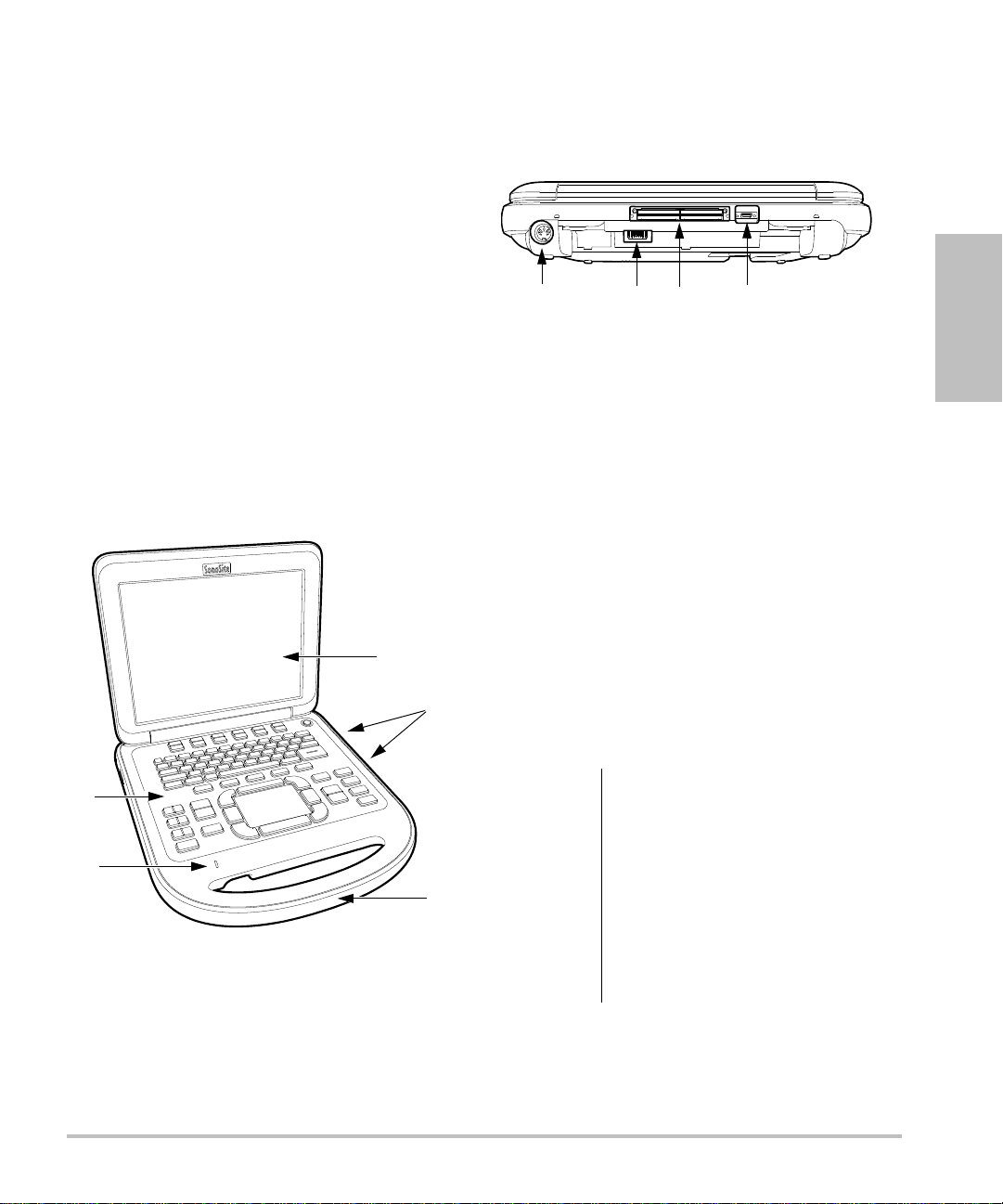
About the system
The Edge ultrasound system is a portable,
software-controlled device using all-digital
architecture. The system has multiple
configurations and feature sets used to acquire and
display high-resolution, real-time ultrasound
images. Features available on your system depend
on system configuration, transducer, and exam
type.
A license key is required to activate the software.
See “Software licensing” on page 90. On
occasion, a software upgrade may be required.
FUJIFILM SonoSite provides a USB device
containing the software. One USB device can be
used to upgrade multiple systems.
Figure 2 System Back Connectors:
(1) DC input connector, (2) Battery,
(3) I/O connector, and (4) ECG connector
Basic operating steps
1 Attach a transducer.
2 Turn the system on. (For power switch location,
see “System controls” on page 6.)
Getting Started
Figure 1 System Front Features:
(1) Control panel, (2) AC power indicator, (3)
Display, (4) USB ports, (5) Handle
3 Press the
information form.
4 Press an imaging mode key: 2
or
DOPPLER.
PATIENT key, and complete the patient
D, MMODE, COLOR,
Preparing the system
Installing or removing the battery
WARNING:
WARNING:
To avoid injury to the operator and
to prevent damage to the
ultrasound system, inspect the
battery for leaks prior to installing.
To avoid data loss and to conduct a
safe system shutdown, always
keep a battery in the system.
See also “Battery safety” on
page 100.
Chapter 1: Getting Started 1
Page 14
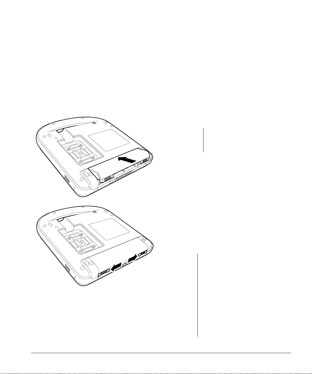
To install the battery
1 Disconnect the power supply from the
ultrasound system.
To remove the battery
1 Disconnect the power supply from the
ultrasound system.
2 Remove the system from the mini-dock (if
present) and turn it upside down.
3 Place the battery into the battery compartment,
at a slight angle. See Figure 3.
4 Slide the battery forward until it locks into place.
5 Slide the two locking levers outward to secure
the battery.
2 Remove the system from the mini-dock
(if present) and turn it upside down.
3 Pull up the two locking levers.
4 Slide the battery back.
5 Lift the battery from the compartment.
Using AC power and charging the
battery
Caution:
The battery charges when the system is connected
to the AC power supply. A fully discharged battery
recharges in less than five hours.
The system can run on AC power and charge the
battery if AC power is connected to the system
directly, to a mini-dock, or to a docking system.
The system can run on battery power for up to two
hours, depending on the imaging mode and the
display brightness. When running on battery
power, the system may not restart if the battery
is low. To continue, connect the system to AC
power.
When using AC power,
position the system to allow
easy access to disconnect it.
WARNING:
Figure 3 Install the Battery
Caution:
2 Preparing the system
The equipment shall be connected
to a center-tapped single phase
supply circuit when users in the
United States connect the
equipment to a 240V supply
system.
Verify that the hospital supply
voltage corresponds to the power
supply voltage range. See
“Electrical specifications” on
page 118.
Page 15

To operate the system using AC power
1 Connect the DC power cable from the power
supply to the connector on the system. See
Figure 2 on page 1.
Push the cable in firmly to ensure a secure
attachment.
2 Connect the AC power cord to the power supply
and to a hospital-grade electrical outlet.
To separate the system (and any
connected equipment) from a supply
mains
Note: Disconnecting only the DC power cable from
the system or dock does not separate the system
from the supply mains.
Disconnect the AC power cord from the power
supply or (alternatively, if using a stand) from
the AC adapter on the stand base.
Turning the system on or off
Caution:
Do not use the system if an error
message appears on the display.
Note the error code and turn off
the system. Call FUJIFILM SonoSite
or your local representative.
Connecting transducers
WARNING:
Caution:
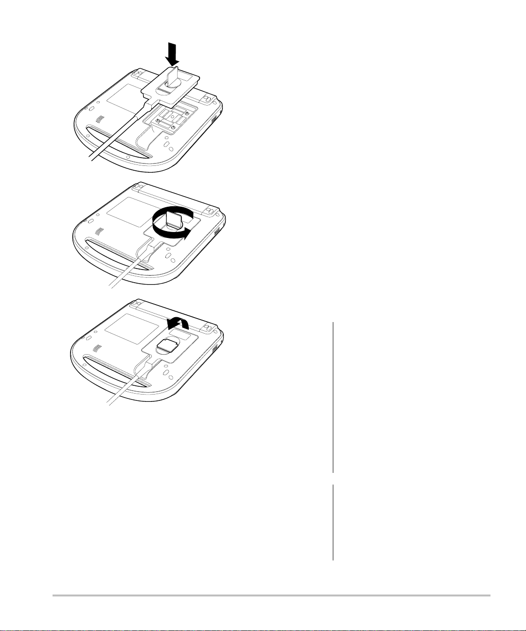
To connect a transducer
1 Remove the system from the mini-dock
(if present), and turn it upside down.
2 Pull the transducer latch up, and rotate it
clockwise.
3 Align the transducer connector with the
connector on the bottom of the system.
4 Insert the transducer connector into the system
connector.
5 Turn the latch counterclockwise.
6 Press the latch down, securing the transducer
connector to the system.
To avoid injury to the patient, do
not place the connector on the
patient. Operate the ultrasound
system in a docking system or on a
flat hard surface to allow air flow
past the connector.
To avoid damaging the transducer
connector, do not allow foreign
material in the connector.
Getting Started
To turn the system on or off
Press the power switch. (See “System
controls” on page 6.)
To wake up the system
To conserve battery life while the system is on, the
system goes into sleep mode if the lid is closed or if
the system is untouched for a preset time. To adjust
the time for sleep delay, see “Audio, Battery
setup” on page 19.
Press a key, touch the touchpad, or open the lid.
Chapter 1: Getting Started 3
Page 16
Inserting and removing USB storage
devices
You can use a USB storage device to import and
export various logs and setup configurations and to
archive images and clips.
Images and clips are saved to internal storage and
are organized in a sortable patient list. You can
archive the images and clips from the ultrasound
system to a PC using a USB storage device or
Ethernet connection. Although the images and clips
cannot be viewed from a USB storage device on the
ultrasound system, you can remove the device and
view them on your PC.
There are two USB ports on the system, and one on
the mini-dock. For additional USB ports, you can
connect a USB hub into any USB port.
Note:
The system does not support
password-protected
sure that the USB storage device you use does not
have
password protection enabled. See also
“Troubleshooting”
USB storage devices. Make
on page 89.
WARNING:
Figure 4 Connect the Transducer
To remove a transducer
1 Pull the transducer latch up, and rotate it
clockwise.
2 Pull the transducer connector away from the
system.
4 Preparing the system
Caution:
To avoid damaging the USB
storage device and losing patient
data from it, observe the following:
• Do not remove the USB storage
device or turn off the ultrasound
system while the system is
exporting.
• Do not bump or otherwise apply
pressure to the USB storage
device while it is in a USB port on
the ultrasound system. The
connector could break.
If the USB icon does not appear in
the system status area on-screen,
the USB storage device may be
defective or password-protected.
Turn the system off and replace
the device.
Page 17

To insert a USB storage device
Insert the USB storage device into any USB port
on the system or mini-dock. See Figure 1 on
page 1.
The USB storage device is ready when the USB
icon appears.
To view information about the device, see
“USB Devices setup” on page 22.
To remove a USB storage device
Removing the USB storage device while the
system is exporting to it may cause the exported
files to be corrupted or incomplete.
1 Wait five seconds after the USB animation stops.
2 Remove the USB storage device from the port.
Getting Started
Chapter 1: Getting Started 5
Page 18
System controls
1
2
3
5
4
7
8
12
13
19
14
16
18
15
6
109
11
17
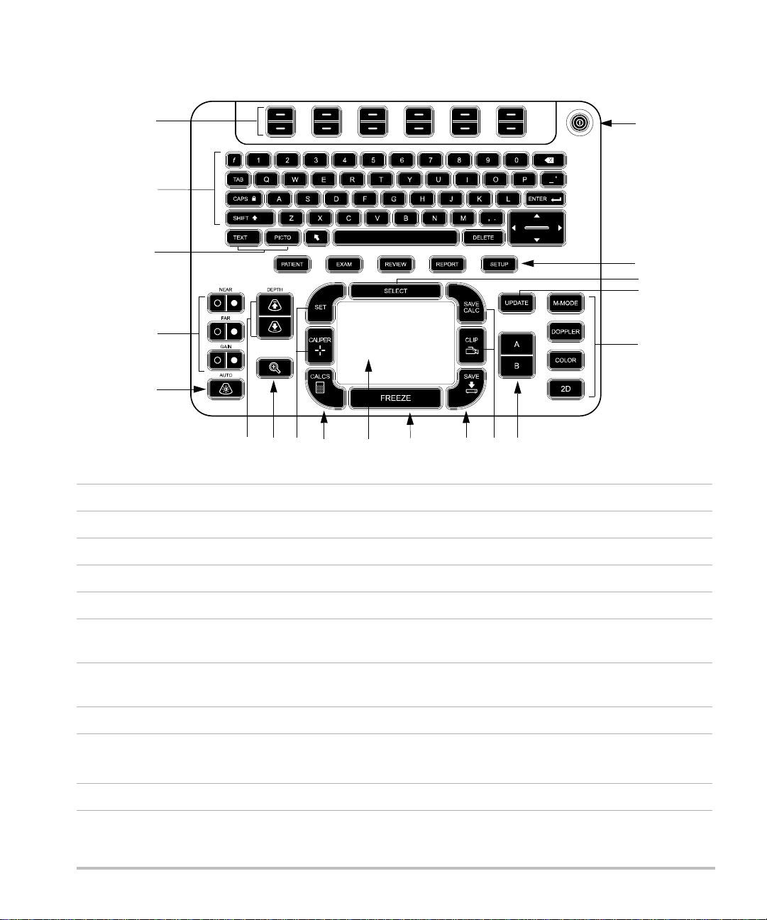
1 Control keys Adjust on-screen controls.
2 Alphanumeric keys Enters text and numbers.
3 Annotation keys See “Alphanumeric keyboard” on page 10.
4 Gain
NEAR Adjusts the gain applied to the near field of the image.
FAR In live imaging, adjusts the gain applied to the far field of the image.
On a frozen PW Doppler image, adjusts the angle.
GAIN In live imaging, adjusts the overall gain applied to the entire image.
On a frozen image, moves the cine buffer.
5 AUTO GAIN Adjusts gain automatically.
6
DEPTH UP,
Decreases and increases imaging depth.
DEPTH DOWN
7 ZOOM Magnifies the image 100%.
6 System controls
Page 19

8SET
CALIPER
Sets a trace measurement.
Displays calipers on-screen for measuring.
9 CALCS Turns the calculations menu on and off.
10 Touchpad Selects, adjusts, and moves items on-screen.
11 FREEZE Stops live imaging and displays a frozen image.
12 SAVE Saves an image to internal storage. If configured, also saves calculations
to the report. See “Presets setup” on page 22.
13 SAVE CALC
CLIP
14
A & B shortcut keys Keys that you can program to perform common tasks.
15
Imaging Modes
Saves calculations and their measurements to the patient report.
Saves a clip to internal storage.
M MODE Turns M Mode on, toggles between M-line and M Mode trace.
DOPPLER Turns Doppler on, toggles between D-line and Doppler trace.
COLOR Turns CPD/Color on and off.
2D Turns 2D on.
16 UPDATE Toggles between dual and duplex screens and imaging modes in
M Mode and Doppler (for example, between D-line and Doppler
spectral trace).
17 SELECT Used with the touchpad to select items on-screen. Also switches
between Color and Doppler controls, calipers for measurement,
pictograph-marker position and angle, frozen images in duplex and dual
screens, and arrow position and orientation.
18
Forms
Getting Started
PATIENT Accesses patient information.
EXAM Opens exam menu.
REVIEW Accesses the patient list, saved images, and archiving functions.
REPORT Accesses the patient report and EMED worksheets.
19 Power switch Turns system on and off.
Chapter 1: Getting Started 7
Page 20
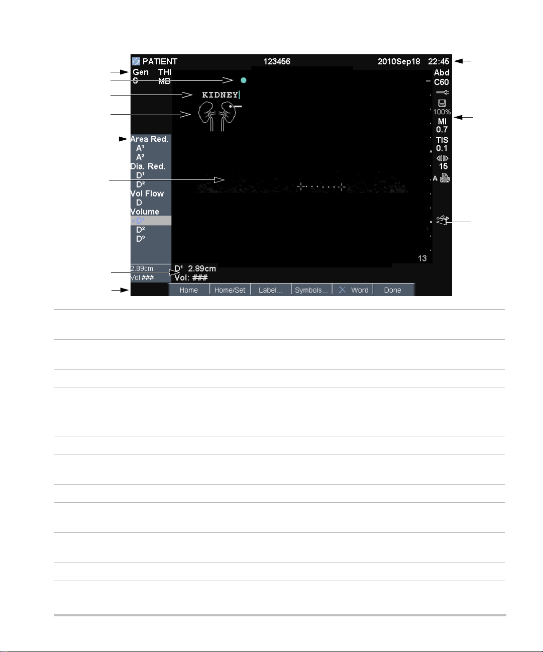
Screen layout
1
5
4
6
11
10
9
7
3
8
2
1 Mode Data Area Current imaging mode information (for example, Gen, Res, THI,
and PW).
2 Orientation Marker Indication for image orientation. In dual and duplex images, the
orientation marker is green on the active screen.
3 Text Text entered using keyboard.
4 Pictograph Pictograph to indicate anatomy and transducer position. You can select
anatomy and screen location.
5 Calculations Menu Contains available measurements.
6 Image Ultrasound image.
7 Measurement and
Current data on measurements and calculations.
Calculations Data Area
8 On-screen Controls Controls available in the current context.
9 Patient Header Header details such as current patient name, ID number, user, and
date/time. Specified on the display information setup page.
10 System Status Information on system status (for example, exam type, transducer,
AC connected, battery charging, and USB).
11 Depth Marker Marks in .5 cm, 1 cm, and 5 cm increments depending on depth.
8 Screen layout
Page 21

General interaction
Touchpad and cursor
Caution:
Use the touchpad to adjust and move objects
on-screen. The touchpad controls caliper position,
CPD or Color box position and size, the cursor, and
more. The arrow keys control much of the same
functionality as the touchpad.
The cursor appears in the setup pages, the patient
information form, and patient report. You control
the cursor through the touchpad. For example, in
the patient information form, place the cursor over
the last name field and press the
activate that field. Additionally, you can use the
cursor to select check boxes and items in lists.
Make sure to keep the touchpad
dry while in use. Moisture on the
touchpad can cause the cursor to
respond erratically.
SELECT key to
On-Off Turns a feature on or off. You can press
either key. In forms, you can instead select the
control by using the touchpad and the
Action Performs an action. You can press either
key. Or you can instead select the control by using
the touchpad and the
Figure 5 On-screen controls (2D imaging shown)
SELECT key.
SELECT key.
Getting Started
On-screen controls
The on-screen controls let you make adjustments
and select settings. The controls available depend
on context.
Each control is controlled by the pair of keys below
it. Depending on the control, the keys function in
one of four ways:
Cycle Moves through a list of settings continuously.
The upper key cycles upward. The lower key cycles
downward.
Up-Down Moves through a list of settings,
stopping at the top or bottom. The upper key
moves upward. The lower key moves downward.
By default, a beep sounds when you reach either
end of the range. (See “Audio, Battery setup”
on page 19.)
Chapter 1: Getting Started 9
Page 22
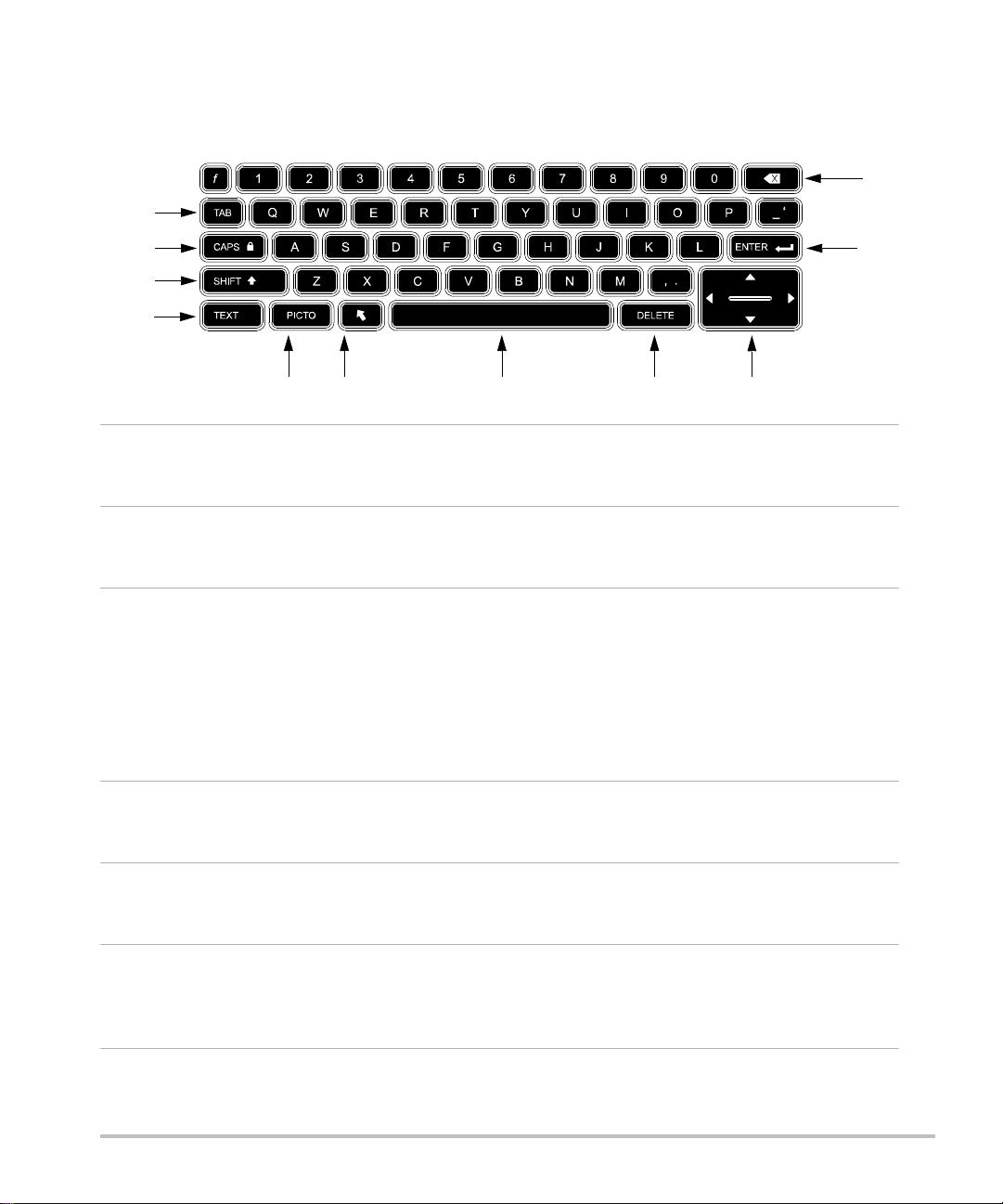
Annotation and text
2
3
4
11
10
1
56 8 97
Alphanumeric keyboard
1 TAB Moves cursor among fields in
the forms, and tabs between
text position in dual screens.
2
CAPS
LOCK
Sets the keyboard to capital
letters.
7 SPACEBAR Turns the keyboard on for
text entry. In text entry,
adds a space.
8 DELETE Removes all text from the
screen during text entry and
when not measuring.
3
SHIFT Allows entry of capitalized
characters and international
characters.
9Arrow
Keys
Move highlighted selection
in calculations menu, move
cursor one space when
entering text, move caliper
position, move cine buffer
forward and backward, and
move among pages in
image review and reports.
4
TEXT Turns the keyboard on and
off for text entry.
10 BACKSPACE Removes the character left
of the cursor in text-entry
mode.
5
PICTO Turns pictographs on and off. 11 ENTER Moves cursor among fields
in forms and saves
calculations to report.
6
ARROW Displays an arrow graphic
that can be moved and
rotated within the image
area.
10 General interaction
Page 23
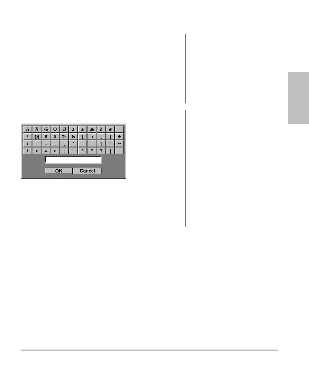
Symbols
You can enter symbols and special characters in
select fields and forms. The symbols and special
characters available depend on context.
Patient information form: Last, First, Middle,
Patient ID, Accession, Indications, Procedure ID,
User, Reading Dr., Referring Dr., and Institution
fields
DICOM or SiteLink configuration page: Alias and
AE Title fields
A & B Key, Footswitch setup page: Text field
Text mode (imaging): Annotation field
Figure 6 Symbols Dialog Box
To enter symbols or special characters
1 Select the field, and then select Symbols.
2 Select the desired symbol or character.
Preparing transducers
WARNING:
WARNING:
Caution:
Caution:
Some transducer sheaths contain
natural rubber latex and talc, which
can cause allergic reactions in
some individuals. Refer to
21 CFR 801.437, User labeling for
devices that contain natural rubber.
Some gels and sterilants can cause
an allergic reaction on some
individuals.
To avoid damage to the
transducer, use only gels
recommended by FUJIFILM
SonoSite. Using gels other than
the one recommended by
FUJIFILM SonoSite can damage
the transducer and void the
warranty. If you have questions
about gel compatibility, contact
FUJIFILM SonoSite or your local
representative.
FUJIFILM SonoSite recommends
that you clean transducers after
each use. See “Cleaning and
disinfecting transducers” on
page 92.
Getting Started
You can also press the keys on the keyboard.
3 Select OK.
Acoustic coupling gel must be used during exams.
Although most gels provide suitable acoustic
coupling, some gels are incompatible with some
transducer materials. FUJIFILM SonoSite
recommends Aquasonic
with the system.
For general use, apply a liberal amount of gel
between the transducer and the body. For invasive
or surgical use, apply a transducer sheath.
®
gel and provides a sample
Chapter 1: Getting Started 11
Page 24

4 Select the Videos tab.
WARNING:
To prevent contamination, the use
of sterile transducer sheaths and
sterile coupling gel is
recommended for clinical
applications of an invasive or
surgical nature. Do not apply the
transducer sheath and gel until you
are ready to perform the
procedure.
To apply a transducer sheath
FUJIFILM SonoSite recommends the use of
market-cleared, transducer sheaths for
intracavitary or surgical applications.To lessen the
risk of contamination, apply the sheath only when
you are ready to perform the procedure.
1 Place gel inside the sheath.
2 Insert the transducer into the sheath.
3 Pull the sheath over the transducer and cable
until the sheath is fully extended.
4 Secure the sheath using the bands supplied
with the sheath.
5 Check for and eliminate bubbles between the
face of the transducer and the sheath.
Bubbles between the face of the transducer and
the sheath may affect the ultrasound image.
6 Inspect the sheath to ensure that there are no
holes or tears.
5 If the list does not appear, select the correct USB
device:
a Select Select USB.
b In the Select USB device for media
playback dialog box, select the Education
Key USB device (“Training” appears under
Type), and then select Select.
Note: Image Gallery is an unsupported feature.
To view a video
1 Display the list of videos.
2 Select the video.
3 Select View on-screen.
The video begins playing.
4 Select any of the following, as needed:
• Adjusts the volume. The higher the
number, the louder the sound. Zero is mute.
• Back Rewinds the video 10 seconds.
• Pause Pauses the video.
• Play Resumes playing of a paused video.
• Forward Advances the video 10 seconds.
To exit a video
Select one of the following:
• List to return to the video list.
• Done to return to 2D imaging.
Training videos
The SonoSite® Education Key™ training videos are
an optional feature.
To display the list of videos
1 Insert the Education Key USB device into a USB
port on the system.
2 Press the
3 If there is an active exam, select List on-screen.
12 Training videos
REVIEW key.
Page 25

Intended uses
The system is used with a transducer attached and
is powered either by battery or by AC electrical
power. The clinician is positioned beside the patient
and places the transducer onto (or into for invasive
procedures) the patient’s body where needed to
obtain the desired ultrasound image.
The system transmits ultrasound energy into the
patient’s body to obtain ultrasound images as listed
below.
For the intended transducer and imaging modes for
each exam type, see “Imaging modes and exams
available by transducer” on page 33.
Abdominal Imaging Applications You can assess
the liver, kidneys, pancreas, spleen, gallbladder, bile
ducts, transplanted organs, abdominal vessels, and
surrounding anatomical structures for the presence
or absence of pathology transabdominally.
Cardiac Imaging Applications You can assess the
heart, cardiac valves, great vessels, surrounding
anatomical structures, overall cardiac performance,
and heart size for the presence or absence of
pathology.
In addition, you can identify the presence and
location of fluid around the heart and lungs, use to
assist in pericardiocentesis and thoracentesis
procedures, visualize blood flow through cardiac
valves, and detect normal lung motion for the
presence or absence of pathology.
You can obtain the patient’s electrocardiogram
(ECG). The ECG is used for timing of cardiac
events.
WARNING:
The ECG is not used to diagnose
cardiac arrhythmias and is not
designed for long term cardiac
rhythm monitoring.
Gynecology and Infertility Imaging
Applications You can assess the uterus, ovaries,
adnexa, and surrounding anatomical structures for
the presence or absence of pathology
transabdominally or transvaginally.
Interventional Imaging Applications You can use
the system for ultrasound guidance in biopsy and
drainage procedures, vascular line placement,
peripheral nerve blocks, spinal nerve blocks and
taps, ova harvesting, amniocentesis and other
obstetrical procedures, and provide assistance
during abdominal, breast, and neurological surgery.
Obstetrical Imaging Applications You can assess
the fetal anatomy, viability, estimated fetal weight,
gestational age, amniotic fluid, and surrounding
anatomical structures for the presence or absence
of pathology transabdominally or transvaginally.
CPD and Color imaging are intended for high-risk
pregnant women. High-risk pregnancy indications
include, but are not limited to, multiple pregnancy,
fetal hydrops, placental abnormalities, as well as
maternal hypertension, diabetes, and lupus.
WARNING:
WARNING:
To prevent injury or misdiagnosis,
do not use this system for
Percutaneous Umbilical Blood
Sampling (PUBS) or in vitro
Fertilization (IVF) The system has
not been validated to be proven
effective for these two uses.
CPD or Color images can be used
as an adjunctive method, not as a
screening tool, for the detection of
structural anomalies of the fetal
heart and as an adjunctive method,
not as a screening tool, for the
diagnosis of Intrauterine Growth
Retardation (IUGR).
Getting Started
Chapter 1: Getting Started 13
Page 26

Pediatric and Neonatal Imaging Applications
You can assess the pediatric and neonatal
abdominal, pelvic and cardiac anatomy, pediatric
hips, neonatal head, and surrounding anatomical
structures for the presence or absence of
pathology.
Superficial Imaging Applications You can assess
the breast, thyroid, testicle, lymph nodes, hernias,
musculoskeletal structures, soft tissue structures,
ophthalmic structures, and surrounding anatomical
structures for the presence or absence of
pathology. You can use the system for ultrasound
guidance in biopsy and drainage procedures,
vascular line placement, peripheral nerve blocks,
and spinal nerve blocks and taps.
Vascular Imaging Applications You can assess
the carotid arteries, deep veins, and arteries in the
arms and legs, superficial veins in the arms and legs,
great vessels in the abdomen, and various small
vessels feeding organs for the presence or absence
of pathology.
WARNING:
To avoid injury to the patient, use
only an Orbital (Orb) or
Ophthalmic (Oph) exam type
when performing imaging through
the eye. The FDA has established
lower acoustic energy limits for
ophthalmic use. The system will
not exceed these limits only if the
Orb or Oph exam type is selected.
Transcranial Imaging Applications You can
assess the anatomical structures and vascular
anatomy of the brain for presence or absence of
pathology. You can use imaging temporally,
trans-occipitally, or trans-orbitally.
WARNING:
To avoid injury to the patient, use
only an Orbital (Orb) or
Ophthalmic (Oph) exam type
when performing imaging through
the eye. The FDA has established
lower acoustic energy limits for
ophthalmic use. The system will
not exceed these limits only if the
Orb or Oph exam type is selected.
14 Intended uses
Page 27

Chapter 2: System Setup
The system setup pages let you customize the
system and set preferences.
Displaying the setup pages
To display a setup page
1 Press the SETUP key.
2 Select the setup page under Setup Pages.
To return to imaging from a setup page, select
Done on-screen.
Restoring default settings
To restore default settings for a setup page
On the setup page, select Reset on-screen.
To restore all default settings
1 Turn the system off.
2 Connect the system to AC power. (See “To
operate the system using AC power” on
page 3.)
3 Simultaneously press 1 and the power key.
The system beeps several times.
A & B Key, Footswitch setup
Footswitch (L), Footswitch (R) The function of
the left and right footswitches: Save Clip, Freeze,
Save Image, or Print. See also “To connect the
footswitch.”
To connect the footswitch
The FUJIFILM SonoSite footswitch allows
hands-free operation with a customizable
two-pedal footswitch. The footswitch is an optional
feature.
WARNING:
1 Connect the footswitch USB cable to the USB
port on the system or mini-dock.
2 On the A & B Key, Footswitch setup page, select
a function for the left and right footswitches.
To avoid contamination, do not use
the footswitch in a sterile
environment. The footswitch is not
sterilized.
Administration setup
On the Administration setup page, you can
configure the system to require users to log in and
enter passwords. Required login helps protect
patient data. You can also add and delete users,
change passwords, import and export user
accounts, and view the event log.
Setup
On the A & B Key, Footswitch setup page, you can
program the shortcut keys and footswitch to
perform common tasks. Select from the following
lists:
A Key, B Key The function of the shortcut keys. By
default, the A shortcut key is set to Print and the B
shortcut key is set to none. The shortcut keys are
below the alphanumeric keypad.
Chapter 2: System Setup 15
Page 28

Security settings
WARNING:
Health care providers who
maintain or transmit health
information are required by the
Health Insurance Portability and
Accountability Act (HIPAA) of
1996 and the European Union
Data Protection Directive
(95/46/EC) to implement
appropriate procedures: to ensure
the integrity and confidentiality of
information; to protect against any
reasonably anticipated threats or
hazards to the security or integrity
of the information or unauthorized
uses or disclosures of the
information.
2 In the User Login list, select On.
• On requires a user name and password at
startup.
• Off allows access to the system without a
user name and password.
To change the administrator password or
let users change passwords
1 Log in as Administrator.
2 Under User List, select Administrator.
3 Do any of the following:
• Change the administrator password: Under
User Information, type the new password
in the Password box and Confirm box.
(See “Choosing a secure password” on
page 18.)
Security settings on the system allow you to meet
the applicable security requirements listed in the
HIPAA standard. Users are ultimately responsible
for ensuring the security and protection of all
electronic protected health information collected,
stored, reviewed, and transmitted on the system.
To log in as Administrator
1 On the Administration setup page, type
Administrator in the Name box.
2 Type the administrator password in the
Password box.
If you don’t have the administrator password,
contact FUJIFILM SonoSite. (See “FUJIFILM
SonoSite Technical Support” on page ix.)
3 Select Login.
To log out as Administrator
Turn off or restart the system.
To require user login
You can set the system to display the User Login
screen at startup.
1 Log in as Administrator.
• Let users change their passwords: Select
the Password changes check box.
4 Select Save.
User setup
To add a new user
1 Log in as Administrator.
2 Select New.
3 Under User Information, fill in the Name,
Password, and Confirm boxes. (See
“Choosing a secure password” on page 18.)
4 (Optional) In the User box, type the user’s
initials to display them in the patient header and
the User field in the patient information form.
5 (Optional) Select the Administration Access
check box to allow access to all administration
privileges.
6 Select Save.
To modify user information
1 Log in as Administrator.
2 Under User List, select the user.
16 Administration setup
Page 29

3 Under User Information, make changes as
desired.
4 Select Save.
3 Select Import on-screen.
4 Select the USB storage device, and select
Import.
Any change to the user name replaces the previous
name.
To delete a user
1 Log in as Administrator.
2 Under User List, select the user.
3 Select Delete.
4 Select Yes.
To change a user password
1 Log in as Administrator.
2 In the User List, select the user.
3 Type the new password in the Password box
and Confirm box.
4 Select Save.
Exporting or importing user accounts
The export and import commands let you configure
multiple systems and back up user account
information.
To export user accounts
1 Insert a USB storage device.
2 Log in as Administrator.
3 Select Export on-screen. A list of USB devices
appears.
4 Select the USB storage device, and select
Export.
All user names and passwords are copied to the
USB storage device. Passwords are encrypted.
To import user accounts
1 Insert the USB storage device that contains the
accounts.
5 Restart the system.
All user names and passwords on the system
are replaced with the imported data.
Exporting and clearing the Event log
The Event log collects errors and events and can be
exported to a USB storage device and read on a PC.
To display the Event log
1 Log in as Administrator.
2 Select Log on-screen.
The Event log appears.
To return to the previous screen, select Back.
To export the Event log
The Event log and the DICOM network log have the
same file name (log.txt). Exporting either one to a
USB storage device overwrites any existing log.txt
file.
1 Insert a USB storage device.
2 Select Log and then select Export on-screen.
A list of USB devices appears.
3 Select the USB storage device, and select
Export.
The Event log is a text file that you can open in a
text-editing application (for example, Microsoft
Word or Notepad).
To clear the Event log
1 Display the Event log.
2 Select Clear on-screen.
3 Select Yes.
Setup
2 Log in as Administrator.
Chapter 2: System Setup 17
Page 30

Logging in as user
If user login is required, the User Login screen
appears when you turn on the system. (See “To
require user login” on page 16.)
To log in as user
1 Turn on the system.
2 In the User Login screen, type your name and
password, and select OK.
To log in as guest
Guests can scan but can’t access system setup and
patient information.
1 Turn on the system.
2 In the User Login screen, select Guest.
To change your password
1 Turn on the system.
2 In the User Login screen, select Password.
3 Type your old and new passwords, confirm the
new password, and then select OK.
Choosing a secure password
To ensure security, choose a password that
contains uppercase characters (A-Z), lowercase
characters (a-z), and numbers (0-9). Passwords
are case-sensitive.
Annotations setup
On the Annotations setup page, you can customize
predefined labels and set the preference for
managing text when unfreezing images.
1 In the Exam list on the Annotations setup page,
select the exam type whose labels you want to
specify.
2 For Group, select A, B, or C for the label group
you want associated with that exam.
The preset labels appear for the selected group.
3 Do any of the following:
• Add a custom label to the group: Type the
label in the Text box, and select Add.
• Rename a label: Select the label, type the
new name in the Text box, and select
Rename.
• Move a label within the group: Select the
label, and then select the on-screen up or
down arrow.
• Delete a label from a group: Select the label,
and select Delete.
You can use symbols in labels. See “Symbols”
on page 11.
To specify text retention when unfreezing
You can specify which text to keep when you
unfreeze an image or change the imaging layout.
In the Unfreeze list on the Annotations setup
page, select Keep All Text, Keep Home Text,
or Clear All Text.
The default setting is Keep All Text. For
information on setting the home position, see
“To reset the home position” on page 36.
To export predefined label groups
1 Insert a USB storage device.
For instructions to annotate images, see
“Annotating images” on page 35.
To predefine a label group
You can specify which labels are available for an
exam type when annotating an image. (See “To
place text on an image” on page 35.)
18 Annotations setup
2 On the Annotations setup page, select Export.
A list of USB devices appears.
3 Select the USB storage device, and select
Export.
A copy of all predefined label groups for all
exams saves to the USB storage device.
Page 31

To import predefined label groups
1 Insert the USB storage device that contains the
label groups.
2 On the Annotations setup page, select Import
on-screen.
3 Select the USB storage device, and then select
Import.
4 Select Done in the dialog box that appears.
All predefined label groups for all exams are
replaced with those from the USB storage
device.
Audio, Battery setup
On the Audio, Battery setup page, you can select
options in the following lists:
Connectivity setup
On the Connectivity setup page, you specify
options for using non-USB devices and for alerts
when internal storage is full. You also import
wireless certificates and specify settings (including
Transfer Mode and Location) for SiteLink™ Image
Manager and DICOM
For SiteLink issues, refer to the SiteLink Image
Manager user guide. For DICOM issues, such as
storage commitment, archivers, and MPPS refer to
Sending and Receiving DICOM Data.
To configure the system for a printer
1 Set up the printer hardware. (See instructions
included with the printer or docking system.)
2 In the Printer list on the Connectivity setup
page, select the printer.
®
, which are optional features.
Setup
Key click Select On or Off for keys to click when
pressed.
Beep alert Select On or Off for the system to beep
when saving, warning, starting, or shutting down.
Sleep delay Select Off, or 5 or 10 minutes to
specify the period of inactivity before the system
goes into sleep mode.
Power delay Select Off, or 15 or 30 minutes to
specify the period of inactivity before the system
automatically turns off.
Cardiac Calculations setup
On the Cardiac Calculations setup page, you can
specify measurement names that appear in the
Tissue Doppler Imaging (TDI) calculations menu
and on the report page.
See also “Cardiac calculations” on page 53.
To specify cardiac measurement names
Under TDI Walls on the Cardiac Calculations
setup page, select a name for each wall.
To configure the system to export data to
aPC
You can send patient report data as ASCII text from
the system to a PC. The PC must have third-party
software to acquire, view, or format the data into a
report. Check the compatibility of your software
with FUJIFILM SonoSite Technical Support. (See
also “To send a patient report to a PC” on
page 72.)
1 In the Serial Port list on the Connectivity setup
page, select Computer (PC).
2 Restart the system.
3 Attach a serial cable (RS-232) from the serial
port on the mini-dock or docking system to the
peripheral.
To receive storage alerts
On the Connectivity setup page, select Internal
Storage Capacity Alert.
The system displays a message if internal
storage is near capacity when you end an exam.
The system then deletes archived patient
exams if specified in DICOM setup.
Chapter 2: System Setup 19
Page 32

Date and Time setup
WARNING:
To obtain accurate obstetrics
calculations, an accurate date and
time are critical. Verify that the
date and time are accurate before
each use of the system. The
system does not automatically
adjust for daylight saving time
changes.
•Under IMT Calculations, select
measurement names from the lists, or select
None.
The selected names appear in the
calculations menu and in the patient report.
• Type the desired width in the Region width
(mm) box.
Network Status setup
To set the date and time
On the Date and Time setup page, do the
following:
•In the Date box, type the current date.
•In the Time box, type the current time in
24 hour format (hours and minutes).
Display Information setup
On the Display Information setup page, you can
specify which details appear on-screen during
imaging. You can select settings in the following
sections:
Patient Header Information that appears in the
patient header.
Mode Data Imaging information.
System Status System status information.
IMT Calculations setup
On the IMT Calculations setup page, you can
customize the IMT calculations menu. You can
specify up to eight measurement names for both
right side and left side calculations. The
measurement names also appear in the patient
report.
The Network Status setup page displays
information on system IP address, Location,
Ethernet MAC address, and the wireless connection
if any.
OB Calculations setup
On the OB Calculations setup page, you select
authors for OB calculation tables. You can also
import or export additional OB calculation tables.
See also “OB calculations” on page 65.
To specify gestational age and growth
analysis
1 On the OB Calculations setup page, select the
desired OB authors (or select None) in the
measurement lists under Gestational Age and
Growth Analysis.
Selecting an author places the associated
measurement on the calculations menu.
2 (Optional) Select More to display the list of
user-defined custom measurements and to
associate a custom table for the custom
measurement.
This option is available only when a user-defined
custom table has been created for the custom
measurement.
See also “IMT calculations” on page 62.
To customize the IMT calculations menu
On the IMT Calculations setup page, do the
following:
20 Date and Time setup
To export OB calculation tables
1 Insert a USB storage device.
2 On the OB Calculations setup page, select
Export. A list of USB devices appears.
Page 33

3 Select the USB storage device, and select
Export.
All user-defined tables and measurements are
copied to the USB storage device.
1 On the OB Custom Measurements setup page,
highlight the measurement in the Custom
Measurements list.
2 Select Delete Last.
To import OB calculation tables
Tables that you import are added to those already
on the system.
1 Insert the USB storage device that contains the
tables.
2 On the OB Calculations setup page, select
Import on-screen.
3 Select the USB storage device, and then select
Import.
4 Select OK in the dialog box that appears.
The system restarts.
OB Custom Measurements
setup
On the OB Custom Measurements setup page, you
can define measurements that appear in the OB
calculations menu and OB report. OB Custom
Measurements is an optional feature.
See also “OB calculations” on page 65.
To set up OB custom measurements
You can save up to five custom measurements that
appear in the OB calculations menu and OB report.
1 On the OB Custom Measurements setup page,
select New.
2 In the Name box, type a unique name.
3 In the Type list, select the desired measurement
type.
4 Select Save.
To delete an OB custom measurement
If you delete an OB custom measurement during an
exam, the exam ends.
3 Select Yes.
The exam ends, and any tables and report data
associated with the measurement are removed
from the system.
OB Custom Tables setup
On the OB Custom Tables setup pages, you can
customize growth tables that appear in the
calculations menu and patient report.
Gestational Age Table Measurements The
system provides gestational age measurements by
selected authors for GS, CRL, BPD, OFD, HC, TTD,
APTD, AC, FTA, FL, EFW, Tibia, HL, and 5 additional
custom measurement labels.
Growth Analysis Table Measurements The
system provides growth graphs or curves for BPD,
HC, AC, FL, EFW, and HC/AC.
WARNING:
To view OB tables
1 On the OB Calculations or OB Custom
Measurements setup page, select Tables
on-screen.
2 Select the desired table and
measurement/author.
To create a new OB custom table
You can create two custom tables for each OB
measurement.
1 On the OB Calculations or OB Custom
Measurements setup page, select Tables
on-screen.
Prior to use, verify that custom
table data entries are correct. The
system does not confirm the
accuracy of the custom table data
entered by the user.
Setup
Chapter 2: System Setup 21
Page 34

2 Select the desired table (Gestational Age or
Growth Analysis).
3 In the Measurement list, select the
measurement for the custom table.
4 Select New on-screen.
5 In the Author box, type a unique name.
6 Enter the data.
Save Key Behavior of the
saves the image to internal storage. Image/Calcs
saves the image to internal storage and saves the
current calculation to the patient report.
Dynamic Range Settings include -3, -2, -1, 0, +1,
+2, or +3. Negative numbers show higher
contrast images, and positive numbers show lower
contrast images.
SAVE key. Image Only
7 Select Save on-screen.
To display the measurement for the custom table in
the calculations menu, see “To specify
gestational age and growth analysis” on
page 20.
To edit or delete an OB custom table
1 On the OB Calculations or OB Custom
Measurements setup page, select Tables
on-screen.
2 Select the OB custom table.
3 Select one of the following on-screen:
• Edit Enter data, and then select Save
on-screen.
• Delete to remove the custom table. Select
Yes.
Presets setup
The Presets setup page has settings for general
preferences. You can select from the following lists:
Doppler Scale Select cm/s or kHz.
Duplex The layout for displaying M Mode trace and
Doppler spectral trace:1/3 2D, 2/3 Trace; 1/2 2D,
1/2 Trace; or Full 2D, Full Trace.
Live Trace Select Peak or Mean.
Thermal Index You can select TIS, TIB, or TIC. The
default setting is based on exam type: OB is TIB,
TCD is TIC, and all others are TIS.
Units Units for patient height and weight in cardiac
exams: in/ft/lbs or cm/m/kg.
Color Scheme The background color of the display.
Auto save Pat. Form Automatically saves the
patient information form as an image in the patient’s
file.
System Information setup
The System Information setup page displays
system hardware and software versions, patents,
and license information.
See also “To enter a license key” on page 90.
To display patents
On the System Information setup page, select
Patents.
USB Devices setup
On the USB Devices setup page, you can view
information about connected USB devices,
including space availability. You can also specify a
file format for images and clips in patient exams that
you export to a USB storage device. (See “To
export patient exams to a USB storage device”
on page 41.)
To specify a file format for exported
images
1 On the USB Devices setup page, select Export.
22 Presets setup
Page 35

2 Under USB Export, select an export type:
• SiteLink organizes files in a SiteLink-style
folder structure. Clips export in H.264 video
saved as MP4 files. To view them, FUJIFILM
SonoSite recommends QuickTime 7.0 or
later.
• DICOM creates files readable by a DICOM
reader. DICOM is an optional feature.
3 Select an image format for your export type. For
JPEG image format, also select a JPEG
compression. (See also “Limitations of JPEG
format.”)
A high compression has a smaller file size but
less detail.
For SiteLink export type, the image format
affects only still images. For DICOM export type,
the image format affects both still images and
clips.
4 For SiteLink export type, select a sort order
under Sort By.
To return to the previous screen, select Devices.
To include private tags
If you use DICOM export type and a FUJIFILM
SonoSite software product, include private tags on
the images.
On the USB Devices setup page, select Include
private tags.
Note: Because the tags may be incompatible
with some earlier archivers, keep this check box
unselected unless you use FUJIFILM SonoSite
software products. For more information, see the
Edge system’s DICOM conformance statement.
Limitations of JPEG format
When transferring or exporting images in JPEG
format, the system uses lossy compression. Lossy
compression may create images that have less
absolute detail than BMP format and that don’t
render identically to the original images.
In some circumstances, lossy-compressed images
may be inappropriate for clinical use. For example, if
you use images in SonoCalc® IMT software, you
should transfer or export them using BMP format.
SonoCalc IMT software uses a sophisticated
algorithm to measure images, and lossy
compression may cause errors.
For more information on using lossy-compressed
images, consult the industry literature, including the
following references:
“Physics in Medicine and Biology, Quality
Assessment of DSA, Ultrasound and CT Digital
Images Compressed with the JPEG Protocol,”
D Okkalides et al 1994 Phys Med Biol 39
1407-1421 doi: 10.1088/0031-9155/
39/9/008 www.iop.org/EJ/abstract/
0031-9155/39/9/008
“Canadian Association of Radiologists, CAR
Standards for Irreversible Compression in Digital
Diagnostic Imaging within Radiology,”
Approved: June 2008.
www.car.ca/Files/%5CLossy_Compression. pdf
eFilm Lite image-viewer
You can include a copy of the eFilm Lite
image-viewer with exams that you export to a USB
memory stick in DICOM format. eFilm Lite lets you
view DICOM-formatted images on a computer
running Windows.
eFilm Lite is a licensed feature.
WAR NIN G:
Russian characters may appear
incorrectly in eFilm Lite. FUJIFILM
SonoSite recommends that you do
not use the eFilm Lite image-viewer
to view exams exported in Russian.
Setup
Chapter 2: System Setup 23
Page 36

To start eFilm Lite image-viewer after
exporting exams
1 Insert the USB memory stick into your
computer.
2 Display the USB memory stick’s contents.
3 Double-click eFilmLite.bat.
eFilmLite.bat starts the executable file in the
eFilmLite folder. The eFilmLite folder contains
the eFilm Lite software and related files. See
also the eFilm Lite User’s Guide, a PDF file in the
eFilmLite folder.
24 USB Devices setup
Page 37

Chapter 3: Imaging
Imaging modes
The system has a high-performance display and
advanced image-optimization technology that
simplifies user controls. Imaging modes available
depend on the transducer and exam type. See
“Imaging modes and exams available by
transducer” on page 33.
2D imaging
2D is the system's default imaging mode. The
system displays echoes in two dimensions by
assigning a brightness level based on the echo
signal amplitude. To achieve the best possible
image quality, properly adjust the display
brightness, gain, depth settings, viewing angle, and
exam type. Also, select an optimization setting that
best matches your needs.
To display the 2D image
1 Do any of the following:
• Turn on the system.
•Press the 2
2 Adjust controls as desired. See “2D controls.”
2D controls
In 2D imaging, you can select the following
on-screen controls.
Optimize Settings are as follows:
D key.
• Res provides the best possible
resolution.
• Gen provides a balance between
resolution and penetration.
• Pen provides the best possible
penetration.
Some of the parameters optimized
to provide the best image include
focal zones, aperture size,
frequency (center and bandwidth),
and waveform. They cannot be
adjusted by the user.
Dynamic
Range
Dual Displays side-by-side 2D images.
LVO On,
LVO Off
Orientation Select from four image orientations:
Adjusts the grayscale range: -3, -2,
-1, 0, +1, +2, +3.
The positive range increases the
number of grays displayed, and the
negative range decreases the
number of grays displayed.
Select Dual, and then press the
UPDATE key to display the second
screen and to toggle between the
screens. With both images frozen,
press the
between the images.
To return to full-screen 2D imaging,
select Dual or press the 2
LVO On turns on Left Ventricular
Opacification. LVO Off turns off this
control.
Use LVO for cardiac exams in 2D
imaging mode. LVO lowers the
mechanical index (MI) of the
system.
This control depends on transducer
and exam type.
U/R (Up/Right), U/L (Up/Left),
D/L (Down/Left), D/R
(Down/Right).
UPDATE key to toggle
D key.
Imaging
Chapter 3: Imaging 25
Page 38

Brightness Adjusts the display brightness.
Settings range from 1 to 10.
The display brightness affects
battery life. To conserve battery life,
adjust brightness to a lower setting.
Guide Turns guidelines on and off.
Guidelines are for needle guidance,
are an optional feature, and depend
on transducer type.
For transducers with a single-angle
or multi-angle bracket, the
touchpad moves the depth cursor.
If the transducer uses a multi-angle
bracket, select Guide and then
select the angle: A, B, or C. To exit
angle selection, select Back. To clear
the guides, do either of the
following:
• Select the angle again (A, B, or C).
• Exit angle selection and press
Guide.
See also the needle guide’s user
documentation.
Guide is not available when the
ECG cable is connected.
ECG Displays the ECG trace. See “ECG
Monitoring” on page 41.
This feature is optional and requires
a FUJIFILM SonoSite ECG cable.
Clips Displays the clip controls. See “To
capture and save a clip” on
page 38.
THI Turns Tissue Harmonic Imaging on
and off.
When on, THI appears in the upper
left-hand screen. This feature
depends on transducer and exam
type.
Page x/x Indicates which page of controls is
displayed. Select to display the next
page.
M Mode imaging
Motion mode (M Mode) is an extension of 2D. It
provides a trace of the 2D image displayed over
time. A single beam of ultrasound is transmitted,
and reflected signals are displayed as dots of
varying intensities, which create lines across the
screen.
Sector (Cardiac exam) Specifies the
sector width.
SonoMB On is available only for
Sector Full.
SonoMB
(MB)
MBe See “Needle visualization” on
26 Imaging modes
MB On and MB Off turn SonoMB®
multi-beam imaging technology on
and off. When SonoMB is on, MB
appears in the upper left-hand
screen.
SonoMB depends on transducer
and exam type.
page 31.
To display the M-line
1 Press the MMODE key.
Note: If the M-line does not appear, make sure
that the image isn’t frozen.
2 Use the touchpad to position the M-line where
desired.
3 Set controls as desired.
Many optimization and depth controls available
in 2D imaging are also available in M Mode
imaging. See “2D controls” on page 25.
To display the M Mode trace
1 Display the M-line.
2 Adjust the depth if necessary. (See “To adjust
depth” on page 30.)
Page 39

3 Press the MMODE key.
The time scale above the trace has small marks
at 200ms intervals and large marks at
one-second intervals.
on the left-hand screen shows which touchpad
function is active.
4 Adjust controls as desired. See “CPD and
Color controls.”
4 Do any of the following as needed:
• Select the sweep speed (Slow, Med,
or Fast).
•Press the
UPDATE key to toggle between the
M-line and M-Mode trace.
• If using a duplex layout, press the
MMODE
key to toggle between the full-screen
M-line and the duplex layout.
To set a duplex layout, see “Presets
setup” on page 22.
CPD and color Doppler imaging
Color power Doppler (CPD) and color Doppler
(Color) are optional features.
CPD is used to visualize the presence of detectable
blood flow. Color is used to visualize the presence,
velocity, and direction of blood flow in a wide range
of flow states.
To display the CPD or Color image
1 Press the COLOR key.
A ROI box appears in the center of the 2D
image.
2 Select CPD or Color.
The current selection also appears in the upper
left-hand screen.
The Color indicator bar on the upper left-hand
screen displays velocity in cm/s in Color imaging
mode only.
CPD and Color controls
In CPD or Color imaging, you can set the following
on-screen controls.
Color, CPD Toggle between CPD and Color.
The current selection appears in
the upper left-hand screen.
Color
Suppress
Flow
Sensitivity
PRF Scale Select the desired pulse repetition
Wall Filter Settings include Low, Med, and
Shows or hides color information.
You can select Show or Hide
while in live or frozen imaging. The
setting shown on-screen is the
current selection.
The current setting appears
on-screen.
• Low optimizes the system for
low flow states.
• Med optimizes the system for
medium flow states.
• High optimizes the system for
high flow states.
frequency (PRF) setting by
pressing the control keys.
There is a wide range of PRF
settings for each Flow Sensitivity
setting (Low, Med, and High).
Available on select transducers.
High.
Available on select transducers.
Imaging
3 Using the touchpad, position or resize the ROI
box as needed. Press the
SELECT key to toggle
between position and size.
While you position or resize the ROI box, a green
outline shows the change. The ROI box indicator
Steering Select the steering angle setting of
the color ROI box (-15, 0, or
+15). If adding PW Doppler, see
“PW Doppler controls” on
page 29.
Available on select transducers.
Chapter 3: Imaging 27
Page 40

Variance Turns variance on and off.
Available only for cardiac exam.
2 Do any of the following as needed:
• Adjust controls. See “PW Doppler
controls” on page 29.
Invert Switches the displayed direction of
flow.
Available in Color imaging.
Sector (Cardiac exam) Specifies the
sector width.
Page x/x Indicates which page of controls is
displayed. Select to display the
next page.
PW and CW Doppler imaging
Pulsed wave (PW) Doppler and continuous wave
(CW) Doppler imaging modes are optional
features.
PW Doppler is a Doppler recording of blood flow
velocities in a range specific area along the length of
the beam. CW Doppler is a Doppler recording of
blood flow velocities along the length of the beam.
You can use PW/CW Doppler and CPD/Color
simultaneously. If CPD/Color imaging is on, the color
ROI box is tied to the D-line. The
among color ROI box position; color ROI box size;
the D-line and gate location; and (in PW Doppler)
angle correction. The active selection is green. Also,
the indicator on the left-hand screen shows which
touchpad function is active.
To display the D-line
The default Doppler imaging mode is PW Doppler.
In cardiac exams, you can select the CW Doppler
on-screen control.
1 Press the
Note: If the D-line does not appear, make sure
that the image isn’t frozen.
DOPPLER key.
SELECT key cycles
• Using the touchpad, position the D-line and
gate where desired. Horizontal movements
position the D-line. Vertical movements
position the gate.
• (PW Doppler) To correct the angle
manually, do one of the following:
•Press the
SELECT key and then use the
touchpad.
The
SELECT key toggles between the
D-line and angle correction.
• Freeze the image, and then press the
keys.
You can adjust the angle in 2° increments
from -74° to +74°.
To display the spectral trace
1 Display the D-line.
2 Press the
The time scale above the trace has small marks
at 200 ms intervals and large marks at
one-second intervals.
3 Do any of the following as needed:
• Adjust controls. See “Spectral trace
•Press the
• If using a duplex layout, press the
DOPPLER key.
controls” on page 29.
UPDATE key to toggle between the
D-line and spectral trace.
DOPPLER
key to toggle between the full-screen D-line
and the duplex layout.
To set a duplex layout, see “Presets
setup” on page 22.
28 Imaging modes
Page 41

PW Doppler controls
In PW Doppler imaging, you can set the following
on-screen controls.
Page x/x Indicates which page of controls is
displayed. Select to display the
next page.
PW, CW (Cardiac exam only) Toggle
between PW Doppler and CW
Doppler.
The current selection appears in
the upper left-hand screen.
Angle
Correction
Gate Size Settings depend on transducer and
TDI On,
TDI Off
Corrects the angle to 0°, +60°, or
-60°.
exam type.
In TCD or Orb exams, use the
touchpad to specify the Doppler
gate depth (the depth of the
center of the gate in the Doppler
image). The Doppler gate depth
indicator is on the lower right-hand
screen.
Select TDI On to turn on tissue
Doppler imaging. When on, TDI
appears in the upper left-hand
screen. The default is TDI off.
Available only in cardiac exams.
Spectral trace controls
In spectral trace imaging, you can set the following
on-screen controls.
Scale Select the desired scale (pulse
repetition frequency [PRF])
setting.
(To change the Doppler scale to
cm/s or kHz, see “Presets
setup” on page 22.)
Line Sets the baseline position.
(On a frozen trace, the baseline
can be adjusted if Live Trace is
off.)
Invert Vertically flips the spectral trace.
(On a frozen trace, Invert is
available if Live Trace is off.)
Volume Increases or decreases Doppler
speaker volume (0-10).
Wall Filter Settings include Low, Med, High.
Imaging
Steering Select the desired steering angle
setting. Settings available depend
on the transducer. The PW Doppler
angle correction automatically
changes to the optimum setting.
• -15 and -20 have an angle
correction of -60°.
• 0 has an angle correction of 0°.
• +15 and +20 have an angle
correction of +60°.
You can manually correct the angle
after selecting a steering angle
setting. (See “To display the
D-line” on page 28.)
Available on select transducers.
Sweep
Speed
Live Trace Displays a live trace of the peak or
Page x/x Indicates which page of controls is
Settings include Slow, Med, Fast.
mean. (See “Presets setup” on
page 22 to specify peak or mean.)
displayed. Select to display the
next page.
Chapter 3: Imaging 29
Page 42

Adjusting depth and gain
Freezing, viewing frames,
To adjust depth
You can adjust the depth in all imaging modes but
the trace modes. The vertical depth scale is marked
in 0.5 cm, 1 cm, and 5 cm increments, depending
on the depth.
Press the following keys:
•
UP DEPTH key to decrease the displayed
depth.
•
DOWN DEPTH key to increase the displayed
depth.
As you adjust the depth, the maximum depth
number changes in the lower right screen.
To adjust gain automatically
Press the AUTO GAIN key. The gain adjusts each
time you press this key.
To adjust gain manually
Press the gain keys :
In each pair of gain keys, the left key decreases
gain, and the right key increases gain.
•
NEAR adjusts the gain applied to the near
field of the 2D image.
and zooming
To freeze or unfreeze an image
Press the FREEZE key.
On a frozen image, the cine icon and frame
number appear in the system status area.
To move forward or backward in the cine
buffer
Freeze the image, and do one of the following:
• Press the keys. The left key moves
backward, and right key moves forward.
• Use the touchpad. Left moves backward,
and right moves forward.
•Press the
The frame number changes as you move
forward or backward. The total number of
frames in the buffer appears on-screen in the
system status area.
To zoom in on an image
You can zoom in 2D and Color imaging. You can
freeze or unfreeze the image or change the imaging
mode at any time while zooming.
LEFT ARROW and RIGHT ARROW keys.
•
FAR adjusts the gain applied to the far field of
the 2D image.
•
GAIN adjusts the overall gain applied to the
entire image. In CPD or Color imaging, the
GAIN keys affects the color gain applied to
the region of interest (ROI) box. In PW and
CW Doppler imaging, the
GAIN keys affect
Doppler gain.
Near and far correspond to the time gain
compensation (TGC) controls on other
ultrasound systems.
30 Adjusting depth and gain
1 Press the
ZOOM key. A ROI box appears.
2 Using the touchpad, position the ROI box as
desired.
3 Press the
ZOOM key again.
The image in the ROI box is magnified by 100%.
4 (Optional) If the image is frozen, use the
touchpad or arrow keys to pan the image up,
down, left, and right. (You cannot pan in Dual.)
To exit zoom, press the
ZOOM key again.
Page 43

Needle visualization
1
2
3
4
WARNING:
About MBe
The MBe control turns on SonoMBe™ imaging,
which enhances linear structures within a selected
angle range and can facilitate needle guidance
during catheter placement and nerve-block
procedures. A three- or four-sided outline indicates
the enhancement area. (See Figure 1 on
page 31.)
To avoid incorrect needle
placement when MBe is on:
• Using movement and fluid
injection, verify the needle-tip
location and trajectory. MBe
enhances linear structures within
a selected angle range on the
ultrasound plane. Linear
structures outside the selected
angle range or the ultrasound
plane
—such as a bent
needle
—may be less apparent.
• Note that linear structures are
enhanced only in an outlined
portion of the image. The area
outside the outline remains
unchanged. (See Figure 1 on
page 31.)
• Note that the beam divergence
of a curved array transducer may
prevent a segment of the needle
shaft from showing in the image.
(See Figure 2 on page 32.) The
needle tip may not show.
The MBe control is available in full-screen imaging
only and on the following:
• Transducers: C60x, HFL38x, HFL50x, L25x,
L38xi
• Exams: Breast, Musculoskeletal, Nerve, Small
Parts, Vascular (L25x only), Venous (L25x
only)
Figure 1 Image with MBe on (linear transducer):
1 - Needle
2 - Outlined area enhanced by MBe
3 - Dotted line
4 - Unenhanced area
Imaging
For curved array transducers, MBe can help identify
the direction of the needle, although only segments
of the needle shaft may show in the image. (See
Figure 2 on page 32.) Use movement and fluid
injection to help verify the needle-tip location.
Chapter 3: Imaging 31
Page 44

Figure 2 With a curved array transducer, only
1
2
3
0 - 50°
2
1
segments of the needle shaft may show:
1 - Upper needle shaft
2 - Unshown segment of needle shaft (unshown
segment or segments depend on specific image)
3 - Needle tip
Needle size and angle
Use a 17-gauge to 25-gauge needle
(recommended). Enhancement results can depend
on the type and brand of needle used. For more
information, consult the medical literature on needle
visibility in ultrasound-guided procedures.
You can angle the needle up to 50° from the
transducer surface. (See Figure 3 on page 32.)
Beyond 50°, the needle may be less enhanced.
(MBe has little or no benefit to out-of-plane
procedures. MBe is intended for in-plane
procedures only.)
Figure 3 For best results, angle the needle only up
to 50° from the transducer surface:
1 - Needle
2 - Transducer
MBe subcontrols
When MBe is on, additional controls are available:
• L/R Flip flips the affected area (the outline)
horizontally on the image.
For reorienting the entire image, use the
orientation control . See “2D controls” on
page 25.
• Shallow, Medium, or Steep sets the outline’s
sloped edge, which is indicated by a dotted line.
The current selection is highlighted green.
Linear transducer:
provides a perpendicular intersection with the
dotted line. Within the enhancement area, the
more perpendicular that a linear structure is to
the dotted line, the more it is enhanced.
Similarly, the less perpendicular (and more
parallel) that a linear structure is to the dotted
line, the less it is enhanced.
Curved array transducer:
angled 30° or less from the transducer surface,
use Shallow for best enhancement. For a linear
structure angled 30-40°, use Medium. For a
linear structure angled 40° or greater, use
Steep.
Use whichever setting best
For a linear structure
• Off turns off MBe. Temporarily turning off MBe
can help you identify artifacts and other
structures not of interest.
32 Needle visualization
Page 45

• Back returns to the previous screen. If MBe is
on, MBe is highlighted green and MBe appears
in the mode data area. Pressing MBe again
redisplays the MBe controls.
The transducer you use determines which exam
types are available. In addition, the exam type you
select determines which imaging modes are
available.
If MBe is on, the MB control is unavailable.
Additional recommendations
Avoid setting the gain too high when using MBe, as
unnecessarily high gain can cause artifacts in the
image. Also, respiratory and cardiac movement in
the image may cause bright pulsating artifacts.
If you use MBe frequently, consider using a shortcut
key to turn on the MBe control. For instructions to
program a shortcut key, see “A & B Key,
Footswitch setup” on page 15.
Imaging modes and exams
available by transducer
WARNING:
WARNING:
To prevent misdiagnosis or harm to
the patient, understand your
system’s capabilities prior to use.
The diagnostic capability differs for
each transducer, exam type, and
imaging mode. In addition,
transducers have been developed
to specific criteria depending on
their physical application. These
criteria include biocompatibility
requirements.
To avoid injury to the patient, use
only an Orbital (Orb) or
Ophthalmic (Oph) when
performing imaging through the
eye. The FDA has established
lower acoustic energy limits for
ophthalmic use. The system will
not exceed these limits only if the
Orb or Oph exam type is selected.
To change the exam type
Do one of the following:
•Press the
menu.
• On the patient information form, select from
the Type list under Exam. (See “Patient
information form” on page 36.)
Imaging modes and exams available by
transducer
Transducer
C8x Pro
C11x Abd
C60x Abd
EXAM key, and select from the
Imaging Mode
1
2
2D
Exam Type
3
CPD
M Mode
4
3
Color
PW Doppler
Neo
Nrv
Vas
Gyn
Msk
Nrv
OB
CW Doppler
—
—
—
—
—
—
—
—
—
—
Imaging
Chapter 3: Imaging 33
Page 46

Imaging Mode
Imaging Mode
4
3
Color
PW Doppler
Transducer
D2x Crd
1
3
2
2D
CPD
M Mode
Exam Type
————
HFL38x Bre
IMT
Msk
Nrv
SmP
Vas
Ven
HFL50x Bre
MSK
Nerve
3
Color
4
PW Doppler
CW Doppler
—
—
—
—
—
—
—
—
—
—
—
1
3
2
2D
CPD
CW Doppler
—
—
—
—
—
—
—
—
—
—
Transducer
Exam Type
ICTx Gyn
OB
L25x Msk
Nrv
Oph
Sup
Vas
Ven
L38x Bre
IMT
Nrv
M Mode
SmP
—
SmP
Vas
Ven
L38xi Bre
IMT
Msk
Nrv
SmP
Vas
Ven
—
—
—
—
—
—
—
—
—
—
34 Imaging modes and exams available by transducer
Page 47

Imaging Mode
Imaging Mode
4
3
Color
PW Doppler
Transducer
1
3
2
2D
CPD
M Mode
Exam Type
P10x Abd
Crd
—
Neo
P11x* Vas
Ven
P21x Abd
Crd
—
OB
Orb
TCD
SLAx Msk
Nrv
Sup
Vas
Ven
TEEx Crd
—
3
Color
4
PW Doppler
CW Doppler
Imaging
1
3
2
2D
CPD
CW Doppler
—
—
—
—
—
—
Transducer
*For information about the P11x transducer, see the P11x
Transducer User Guide, included with the P11x
transducer.
1. Exam type abbreviations are as follows: Abd =
Abdomen, Bre = Breast, Crd = Cardiac, Gyn =
Gynecology, IMT = Intima Media Thickness, Msk =
Musculoskeletal, Neo = Neonatal, Nrv = Nerve, OB =
Obstetrical, Oph = Ophthalmic, Orb = Orbital, Pro =
Prostate SmP = Small Parts, Sup = Superficial, TCD =
Transcranial Doppler, Vas = Vascular, Ven = Venous.
2. The optimization settings for 2D are Res, Gen, and Pen.
3. The optimization settings for CPD and Color are low,
medium, and high (flow sensitivity) with a range of PRF
settings for Color depending on the setting selected.
4. For the cardiac exam type, PW TDI is also available. See
“PW Doppler controls” on page 29.
Exam Type
M Mode
Annotating images
—
—
You can annotate live images as well as frozen
images. (You cannot annotate a saved image.) You
can place text (including predefined labels), an
—
—
—
arrow, or a pictograph. To set preferences for
annotations, see “Annotations setup” on
page 18.
To place text on an image
You can place text in the following imaging layouts:
full-screen 2D, full-screen trace, dual, or duplex.
You can place text manually or add a predefined
label.
1 Press the
TEXT key. A green cursor appears.
2 Move the cursor where desired:
• Use the touchpad or arrow keys.
• Select Home to move the cursor to the
home position.
Chapter 3: Imaging 35
Page 48

The default home position depends on the
imaging screen layout. You can reset the
home position. See “To reset the home
position” on page 36.
3 Using the keyboard, type text.
• The arrow keys move the cursor left, right,
up, and down.
•The
DELETE key deletes all text.
• Word removes a word.
• Symbols lets you enter special characters.
See “Symbols” on page 11.
4 (Optional) To add a predefined label, select
Label, and then select the desired label group:
, , or . Select the group again for
the desired label.
The first number shows which label in the group
is selected. The second number is the number of
labels available.
See “Annotations setup” on page 18.
To turn off text entry, press the
TEXT key.
4 Press the
ARROW key to set the arrow.
The arrow changes from green to white.
To remove the arrow, press the
ARROW key and
then select Hide.
To place a pictograph on an image
The pictograph set available depends on transducer
and exam type.
1 Press the
2 Select x/x to display the desired
pictograph, and then press the
The first number shows which pictograph in the
set is selected. The second number is the
number of pictographs available.
3 Using the touchpad, position the pictograph
marker.
4 (Optional) To rotate the pictograph marker,
press the
5 Select a screen location for the pictograph: U/L
(Up/Left), D/L (Down/Left), D/R
(Down/Right), U/R (Up/Right).
PICTO key.
SELECT key.
SELECT key and then use the touchpad.
To reset the home position
1 Press the TEXT key.
2 Using the touchpad or arrow keys, position the
In a duplex layout, the pictograph is restricted to
upper left. In Dual, all four positions are available.
To remove the pictograph, select Hide.
cursor where desired.
3 Select Home/Set.
To place an arrow on an image
You can add an arrow graphic to point out a specific
part of the image.
1 Press the
ARROW key .
Patient information form
The patient information form lets you enter patient
identification, exam, and clinical information for the
patient exam. This information automatically
appears in the patient report.
When you create a new patient information form, all
images, clips, and other data you save during the
2 If you need to adjust the arrow's orientation,
press the
When the orientation is correct, press the
SELECT key and then use the touchpad.
SELECT
key again.
3 Using the touchpad, position the arrow where
exam are linked to that patient. (See “Patient
report” on page 72.)
To create a new patient information form
1 Press the PATIENT key.
desired.
2 Select New/End.
36 Patient information form
Page 49

3 Fill in the form fields. See “Patient information
form fields” on page 37.
4 Select Done.
See also “To append images and clips to a
patient exam” on page 40.
To enable bar code lookup of patient data
You can query the worklist for patient data by
scanning a Patient ID bar code with the bar code
scanner. The patient data are then automatically
entered into the patient information form.
Select Bar Code Auto Lookup on the
Connectivity setup page.
For more information about the bar code scanner,
see Bar Code Scanner User Guide.
To edit a patient information form
You can edit patient information if the exam has not
been archived or exported and if the information is
not from a worklist.
See also “To edit patient information from the
patient list” on page 40.
1 Press the
PATIENT key.
2 Make changes as desired.
3 Select one of the following:
• Cancel to undo changes and return to
imaging.
• Done to save changes and return to
imaging.
To end the exam
1 Make sure that you have saved images and
other data you want to keep. (See “Saving
images and clips” on page 38.)
2 Press the
PATIENT key.
3 Select New/End.
A new patient information form appears.
Patient information form fields
The patient information form fields available depend
on exam type. In some fields you can select
Symbols to enter symbols and special characters.
See “Symbols” on page 11
Patient
• Last, First, Middle Patient name
• ID Patient identification number
• Accession Enter number, if applicable.
•Date of birth
• Gender
• Indications Enter desired text
• User User initials
• Procedure (button) Available if the DICOM
worklist feature is licensed and configured. See
the document Sending and Receiving DICOM
Data on SonoSite Systems.
Select Back to save entries and return to the
previous screen.
Exam
• Type Exam types available depend on
transducer. See “Imaging modes and exams
available by transducer” on page 33.
• LMP Estab. DD (OB or Gyn exam) In an OB
exam, select LMP or Estab. DD and then enter
either the date of the last menstrual period or
the established due date. In a Gyn exam, enter
the date of the last menstrual period. The LMP
date must precede the current system date.
• Twins (OB exam) Select the Twins check box
to display Twin A and Twin B measurements on
the calculations menu and for access to Twin A
and Twin B screens for previous exam data.
.
Imaging
Chapter 3: Imaging 37
Page 50

• Previous Exams (button) (OB exam)
Displays fields for five previous exams. The date
for a previous exam must precede the current
system date. For twins, select Twin A/B to
toggle between Twin A and Twin B screens. (If
the Twin A/B control does not appear, select
Back, and make sure that the Twins check box
is selected.)
The percentage icon in the system status area
shows the percentage of space used in internal
storage. If you try to save an image or clip when no
space remains, the system alerts you that internal
storage is full. To resolve this issue, archive images
and clips that you wish to save, and then delete
them from the system to free up space. See “To
delete images and clips” on page 41.
Select Back to save changes and return to the
previous screen.
• BP (Cardiac, IMT, Orbital, Transcranial, or
Vascular exam) Blood Pressure
• HR (Cardiac, Orbital, Transcranial, or Vascular
exam) Heart Rate. Enter the beats per minute.
Saving the heart rate using a measurement
overwrites this entry.
• Height (Cardiac exam) The patient height in
feet and inches or meters and centimeters. (To
change the units, see “Presets setup” on
page 22.)
• Weight (Cardiac exam) The patient weight in
pounds or kilos. (To change the units, see
“Presets setup” on page 22.)
• BSA (Cardiac exam) Body Surface Area.
Automatically calculated after you enter height
and weight.
• Ethnicity (IMT exam) Ethnic origin
•Reading Dr.
• Referring Dr.
• Institution
• Department ID
To receive alerts when storage is near capacity, see
“To receive storage alerts” on page 19.
To access saved images and clips, open the patient
list. See “Reviewing patient exams” on page 39.
To save an image
Press the SAVE key.
The image saves to internal storage.
By default, the
shortcut during calculations, the
both the image to internal storage and the
calculation to the patient report. See “Presets
setup” on page 22.
SAVE key saves only the image. As a
SAVE key can save
To capture and save a clip
Clips lets you capture, preview, and save clips.
1 Set Clips controls. (See “To set Clips
controls” on page 39.)
2 Press the
One of the following occurs:
•If Prev/Off is selected, the clip saves
•If Prev/On is selected, the clip plays back in
CLIP key.
directly to internal storage.
preview mode. You can select any of the
following on-screen:
Images and clips
Saving images and clips
When you save an image or clip, it saves to internal
storage. The system beeps afterward if Beep Alert
is on, and the percentage icon flashes. (See
“Audio, Battery setup” on page 19.)
38 Images and clips
• A playback speed (1x, 1/2x, 1/4x)
• Pause to interrupt playback
• Left: x or Right: x to remove frames
from the left or right sides of the clip
(where x is the beginning or ending
frame number)
Page 51

• Save to save the clip to internal storage
• Delete to delete the clip
To set Clips controls
Setting Clips controls ensures that clips are
captured to your specifications.
1 In 2D imaging mode, select Clips on-screen.
2 Set controls as desired.
Reviewing patient exams
Caution:
If the internal storage icon does not
appear in the system status area,
internal storage may be defective.
Contact FUJIFILM SonoSite
Technical Support. (See
“FUJIFILM SonoSite Technical
Support” on page ix.)
Clips controls
Time, ECG Time and ECG share the same
location on-screen.
•With Time, capturing is based
on number of seconds. Select
the time duration.
•With ECG, capturing is based
on the number of heart beats.
Select the number of beats.
Preview On,
Preview Off
Prospective,
Retrospective
PrevOn and PrevOff turn the
preview feature on and off.
•With Prev/On, the captured
clip automatically plays
on-screen. The clip can be
trimmed, saved, or deleted.
•With Prev/Off, the clip saves
to internal storage, and the
trim and delete controls are
not available.
Pro and Retro determine how
clips are captured:
•With Pro, a clip is captured
prospectively, after you press
the
CLIP key.
•With Retro, a clip is captured
retrospectively, from
pre-saved data before you
press the
CLIP key.
The patient list organizes saved images and clips in
patient exams. You can delete, view, print, or
archive exams. You can also copy them to a USB
storage device.
Imaging
Figure 4 Patient List
To display the patient list
1 Press the REVIEW key.
2 If there is an active exam, select List on-screen.
To sort the patient list
After the system starts, the patient list is arranged
by date and time, with the most recent patient file
first. You can re-sort the patient list as needed.
Select the column heading that you want to sort
by. Select it again if sorting in reverse order.
Note: The column heading is selectable.
Chapter 3: Imaging 39
Page 52

To select patients in the patient list
Using the touchpad, select the check box for
one or more patients.
Select All selects all patients.
To deselect patients, select checked boxes or
Clear All.
To edit patient information from the
patient list
You can edit the patient name and ID from the
patient list instead of from the patient information
form if the exam is ended but has not been
exported or archived.
1 In the patient list, select the patient.
4 (Clip Only) Select Play.
The clip plays automatically after loading. The
load time depends on clip length.
You can select Pause to freeze the clip and can
select a playback speed
5 Select x/x to cycle to the next image or clip
you want to view.
To return to the patient list, select List. To return to
imaging, select Done.
1x, 1/2x, 1/4x.
Printing, exporting, and deleting
images and clips
2 Select Edit.
3 Fill in the form fields, and select OK.
To append images and clips to a patient
exam
Although you cannot add images and clips to a
patient exam that is ended, you can automatically
start a new patient exam that has the same patient
information. Depending on your archiver, the two
exams appear as one study when exported or
archived.
1 Select the exam in the patient list.
2 Select Append on-screen.
A new patient information form appears. The
form has the same information as the exam you
selected.
To review images and clips
You can review images and clips in only one patient
exam at a time.
1 In the patient list, highlight the patient exam
whose images and clips you want to review.
2 Select Review on-screen.
3 Select x/x to cycle to the image or clip you
want to review.
WARNING:
To avoid damaging the USB
storage device and losing patient
data from it, observe the following:
• Do not remove the USB storage
device or turn off the ultrasound
system while the system is
exporting.
• Do not bump or otherwise apply
pressure to the USB storage
device while it is in a USB port on
the ultrasound system. The
connector could break.
To print an image
1 Verify that a printer is selected. See “To
configure the system for a printer” on
page 19.
2 Do one of the following:
• In the patient list, review the patient’s
images. Select Print when the image
appears.
• With the image displayed, press the
shortcut key.
By default, the
reprogram the
“Presets setup” on page 22.
A shortcut key prints. To
A and B shortcut keys, see
A
40 Images and clips
Page 53

To print multiple images
1 Verify that a printer is selected. See “To
configure the system for a printer” on
page 19.
2 Do one of the following:
To delete images and clips
1 In the patient list, do one of the following:
• If deleting a single image or clip, display it.
(See “To review images and clips” on
page 40.)
• Print all images for multiple patients: Select
one or more patients in the patient list. Then
select Print.
• Print all images for one patient: Highlight the
patient in the patient list, and then select
Print.
Each image appears briefly on-screen while
printing.
To export patient exams to a USB storage
device
You can export patient exams if they are ended.
(See “To end the exam” on page 37.)
A USB storage device is for temporary storage of
images and clips. Patient exams should be archived
regularly. To specify file format, see “USB Devices
setup” on page 22.
1 Insert the USB storage device.
2 In the patient list, select the patient exams you
want to export.
3 Select Exp. USB on-screen. A list of USB
devices appears.
4 Select the USB storage device. If you want to
hide patient information, deselect Include
patient information on images and clips.
Only available USB devices are selectable.
5 Select Export.
The files are finished exporting approximately
five seconds after the USB animation stops.
Removing the USB storage device or turning off
the system while exporting may cause exported
files to be corrupted or incomplete. To stop
in-progress exporting, select Cancel Export.
• If deleting entire patient exams, select them.
2 Select Delete.
A confirmation screen appears.
To manually archive images and clips
You can send patient exams to a DICOM printer or
archiver, or to a PC using SiteLink Image Manager.
DICOM and SiteLink Image Manager are optional
features. For more information about archiving, see
the DICOM and SiteLink Image Manager
documentation.
1 Select one or more patients in the patient list.
2 Select Archive.
To display information about a patient
exam
1 On the patient list, select the exam.
2 Select Info.
ECG Monitoring
ECG Monitoring is an optional feature and requires
a FUJIFILM SonoSite ECG cable.
WARNING:
WARNING:
To prevent misdiagnosis, do not
use the ECG trace to diagnose
cardiac rhythms. The FUJIFILM
SonoSite ECG control is a
non-diagnostic feature.
To avoid electrical interference
with aircraft systems, do not use
the ECG cable on aircraft. Such
interference may have safety
consequences.
Imaging
Chapter 3: Imaging 41
Page 54

Caution:
Use only accessories
recommended by FUJIFILM
SonoSite with the system. Your
system can be damaged by
connecting an accessory not
recommended by FUJIFILM
SonoSite.
To monitor ECG
1 Connect the ECG cable to the ECG connector on
the ultrasound system, mini-dock, or docking
system.
ECG Monitoring turns on automatically.
Note: An external ECG monitor may cause a lag
in the timing of the ECG trace, corresponding
with the 2D image. Biopsy guidelines are not
available when ECG is connected. The ECG
signal may take up to one minute to restabilize
after defibrillator use on the patient.
2 Select ECG on-screen. (ECG may be on
another page. It appears only if the ECG cable is
connected.)
3 Adjust controls as desired.
ECG Monitoring controls
Show/Hide Turns on and off ECG trace.
Gain Increases or decreases ECG gain.
Settings are 0-20.
Position Sets the position of the ECG trace.
Sweep
Settings are Slow, Med, and Fast.
Speed
Delay Displays Line and Save for clip
acquisition delay. (For instructions
to capture clips, see “To capture
and save a clip” on page 38.)
Line The position of the delay line on
the ECG trace. The delay line
indicates where the clip acquisition
is triggered.
Save Saves the current position of the
delay line on the ECG trace. (You
can change the position of the
delay line temporarily. Starting a
new patient information form or
cycling system power reverts the
delay line to the most recently
saved position.)
Select Delay to display these
controls.
42 ECG Monitoring
Page 55

Chapter 4: Measurements
and Calculations
You can measure for quick reference, or you can
measure within a calculation. You can perform
general calculations as well as calculations specific
to an exam type.
Measurements are performed on frozen images.
For references used, see Chapter 5,
“Measurement References.”
Measurements
You can perform basic measurements in any
imaging mode and can save the image with the
measurements displayed. (See “To save an
image” on page 38.) Except for the M Mode HR
measurement, the results do not automatically save
to a calculation and the patient report. If you prefer,
you can first begin a calculation and then measure.
See “Performing and saving measurements in
calculations” on page 47.
Some features may not apply to your system.
Features available depend on your configuration,
transducer, and exam type.
To save a measurement to a calculation
and patient report
1 With the measurement active (green), press
the
CALCS key.
2 From the calculations menu, select a
measurement name.
Working with calipers
When measuring, you work with calipers, often in
pairs. Results based on the calipers’ position appear
at the bottom of the screen. The results update as
you reposition the calipers by using the touchpad. In
trace measurements, the results appear after you
complete the trace.
Outside a calculation, you can add calipers by
pressing the
of calipers and can switch from one set to another,
repositioning them as needed. Each set shows the
measurement result. The active calipers and
measurement result are highlighted green. A
measurement is complete when you finish moving
its calipers.
Within a calculation, calipers appear when you
select from the calculations menu. (See “To select
from the calculations menu” on page 47.)
For an accurate measurement, accurate placement
of calipers is essential.
To switch the active calipers
Do one of the following:
• To switch the active caliper within a set,
• To switch the active set when measuring
CALIPER key. You can have multiple sets
press the
outside a calculation, select Switch
on-screen.
SELECT key.
Measurements
Only measurement names available for the
imaging mode and exam type are selectable.
3 Save the calculation. (See “To save a
calculation” on page 47.)
To start a calculation before measuring, see
“Performing and saving measurements in
calculations” on page 47.
To delete or edit a measurement
With the measurement active (highlighted), do
one of the following:
•To delete, select Delete on-screen.
• To edit, use the touchpad to move the
calipers.
Chapter 4: Measurements and Calculations 43
Page 56

Note: Trace measurements cannot be edited once
set.
To improve precision of caliper placement
Do any of the following:
• Adjust the display for maximum sharpness.
• Use leading edges (closest to the
transducer) or borders for starting and
stopping points.
• Maintain a consistent transducer orientation
for each type of measurement.
• Make sure that the area of interest fills as
much of the screen as possible.
• (2D) Minimize the depth, or zoom.
2D measurements
The basic measurements that you can perform in
2D imaging are as follows:
•Distance in cm
•Area in cm
• Circumference in cm
You can also measure area or circumference by
tracing manually.
2
You can perform a combination of distance, area,
circumference, and manual trace measurements at
one time. The total number possible depends on
their order and type.
To measure distance (2D)
You can perform up to eight distance
measurements on a 2D image.
1 On a frozen 2D image, press the
CALIPER key.
A pair of calipers appears, connected by a
dotted line.
2 Using the touchpad, position the first caliper,
and then press the
SELECT key.
The other caliper becomes active.
3 Using the touchpad, position the other caliper.
If you move the calipers close together, they
shrink and the dotted line disappears.
See “To save a measurement to a calculation
and patient report” on page 43.
To measure area or circumference (2D)
1 On a frozen 2D image, press the CALIPER key.
2 Select Ellipse on-screen.
Note: If you exceed the allowed number of
measurements, Ellipse is not available.
3 Use the touchpad to adjust the size and position
of the ellipse. The
SELECT key toggles between
position and size.
See “To save a measurement to a calculation
and patient report” on page 43.
To trace manually (2D)
1 On a frozen 2D image, press the CALIPER key.
2 Select Manual on-screen.
Note: If you exceed the allowed number of
measurements, Manual is not available.
Figure 1 2D image with two distance and one
circumference measurement
44 Measurements
3 Using the touchpad, position the caliper where
you want to begin.
Page 57

4 Press the SELECT key.
5 Using the touchpad, complete the trace, and
press the
SET key.
See “To save a measurement to a calculation
and patient report” on page 43.
M Mode measurements
The basic measurements that you can perform in
M Mode imaging are as follows:
5 Using the touchpad, position the second vertical
caliper at the peak of the next heartbeat.
See “To save a measurement to a calculation
and patient report” on page 43. Saving the heart
rate measurement to the patient report overwrites
any heart rate entered on the patient information
form.
See also “To measure fetal heart rate (M
Mode)” on page 67.
• Distance in cm/Time in seconds
• Heart Rate (HR) in beats per minute (bpm)
The time scale above the trace has small marks at
200 ms intervals and large marks at one-second
intervals.
To measure distance (M Mode)
You can perform up to four distance measurements
on an image.
1 On a frozen M Mode trace, press the
CALIPER
key.
A single caliper appears.
2 Using the touchpad, position the caliper.
3 Press the
SELECT key to display the second
caliper.
4 Using the touchpad, position the second caliper.
See “To save a measurement to a calculation
and patient report” on page 43.
To measure heart rate (M Mode)
1 On a frozen M Mode trace, press the CALIPER
key.
2 Select HR on-screen.
A vertical caliper appears.
3 Using the touchpad, position the vertical caliper
at the peak of the heartbeat.
4 Press the
A second vertical caliper appears.
SELECT key.
Doppler measurements
The basic measurements that you can perform in
Doppler imaging are Velocity (cm/s), Pressure
Gradient, Elapsed Time, +/x Ratio, Resistive
Index (RI), and Acceleration. You can also trace
manually or automatically.
For Doppler measurements, the Doppler scale must
be set to cm/s. See “Presets setup” on page 22.
To measure Velocity (cm/s) and Pressure
Gradient (Doppler)
1 On a frozen Doppler spectral trace, press the
CALIPER key.
A single caliper appears.
2 Using the touchpad, position the caliper to a
peak velocity waveform.
This measurement involves a single caliper from the
baseline.
See “To save a measurement to a calculation
and patient report” on page 43.
To measure Velocities, Elapsed Time, +/x
Ratio, Resistive Index (RI), and
Acceleration (Doppler)
RI appears only if the velocity associated with the
first caliper is greater than the velocity associated
with the second caliper.
ACC appears only when the velocity associated
with the second caliper is greater than the velocity
associated with the first caliper.
Measurements
Chapter 4: Measurements and Calculations 45
Page 58

1 On a frozen Doppler spectral trace, press the
CALIPER key.
A single caliper appears.
2 Using the touchpad, position the caliper to a
peak systolic waveform.
3 Press the
SELECT key.
A second caliper appears.
4 Using the touchpad, position the second caliper
at the end diastole on the waveform.
See “To save a measurement to a calculation
and patient report” on page 43.
To measure time duration (Doppler)
1 On a Doppler spectral trace, press the CALIPER
key.
2 Press Time on-screen.
A vertical caliper appears.
5 Press the
SET key.
The measurement results appear.
See “To save a measurement to a calculation
and patient report” on page 43.
To trace automatically (Doppler)
After tracing automatically, confirm that the
system-generated boundary is correct. If you are
not satisfied with the trace, obtain a high-quality
Doppler spectral trace image, or trace manually.
(See “To trace manually (Doppler)” on
page 46.)
1 On a frozen Doppler spectral trace, press the
CALIPER key.
2 Select Auto on-screen.
A vertical caliper appears.
3 Using the touchpad, position the caliper at the
beginning of the waveform.
3 Using the touchpad, position the caliper where
desired, and press the
SELECT key.
A second caliper appears.
4 Using the touchpad, position the second caliper
where desired, and press the
SELECT key.
To trace manually (Doppler)
1 On a frozen Doppler spectral trace, press the
CALIPER key.
2 Select Manual on-screen.
A single caliper appears.
3 Using the touchpad, position the caliper at the
beginning of the desired waveform, and press
the
SELECT key.
If calipers are not positioned correctly, the result
is inaccurate.
4 Using the touchpad, trace the waveform.
To make a correction, select Undo on-screen,
backtrack with the touchpad, or press the
BACKSPACE key.
If calipers are not positioned correctly, the
calculation result is inaccurate.
4 Press the
SELECT key.
A second vertical caliper appears.
5 Using the touchpad, position the second caliper
at the end of the waveform.
6 Press the
SET key.
The measurement results appear.
See “To save a measurement to a calculation
and patient report” on page 43.
Automatic trace results
Depending on the exam type, the results from
automatic tracing include the following:
• Velocity Time Integral (VTI)
• Peak Velocity (Vmax)
• Mean Pressure Gradient (PGmean)
• Mean Velocity on Peak Trace (Vmean)
• Pressure Gradient (PGmax)
46 Measurements
Page 59

• Cardiac Output (CO)
• Peak Systolic Velocity (PSV)
• Time Average Mean (TAM)*
• +/× or Systolic/Diastolic (S/D)
• Pulsatility Index (PI)
• End Diastolic Velocity (EDV)
• Acceleration Time (AT)
• Resistive Index (RI)
• Time Average Peak (TAP)
•Gate Depth
To select from the calculations menu
1 On a frozen image, press the CALCS key.
The calculations menu appears.
2 Using the touchpad or arrow keys, highlight the
desired measurement name.
To display additional measurement names,
highlight Next, Prev, or a measurement name
that has ellipses (. . .). Then press the
key.
Only measurement names available for the
imaging mode are selectable.
3 Press the
SELECT key.
SELECT
General calculations
Within calculations, you can save measurement
results to the patient report. You can display,
repeat, and delete measurements from a
calculation. Some measurements can be deleted
directly from the patient report pages. See
“Patient report” on page 72.
Calculation packages depend on exam type and
transducer.
Calculations menu
The calculations menu contains measurements
available for the imaging mode and exam type.
After you perform and save a measurement, the
result saves to the patient report. (See “Patient
report” on page 72.) Also, a check mark appears
next to the measurement name in the calculations
menu. If you highlight the checked measurement
name, the results appear below the menu. If you
repeat the measurement, the results below the
menu reflect either the last measurement or the
average, depending on the measurement.
To close the calculations menu, press the
CALCS key
once (if the menu is active) or twice (if the menu
is inactive).
Performing and saving measurements
in calculations
In performing a measurement within a calculation,
you select from the calculations menu, position the
calipers that appear, and then save the calculation.
Unlike measurements performed outside a
calculation, the calipers appear by selecting from
the calculations menu, not by pressing the
key. The type of calipers that appear depends on
the measurement.
To save a calculation
Do one of the following:
• Save the calculation only: Press the
SAVE CALC key, or select Save on-screen.
The calculation saves to the patient report.
To save the image with the measurements
displayed, see “To save an image” on
page 38.
CALIPER
Measurements
Menu items followed by ellipses (. . .) have
subentries.
• Save both the image and calculation: Press
the
SAVE key if the SAVE key functionality is
set to Image/Calcs. (See “Presets
setup” on page 22.)
Chapter 4: Measurements and Calculations 47
Page 60

The calculation saves to the patient report,
and the image saves to internal storage with
the measurements displayed.
Some measurements can be deleted directly from
the patient report pages. See “Patient report” on
page 72.
Displaying, repeating, and deleting
saved measurements in calculations
To display a saved measurement
Do one of the following:
• Highlight the measurement name in the
calculations menu. The result appears below
the menu.
• Open the patient report. See “Patient
report” on page 72.
To repeat a saved measurement
1 Highlight the measurement name in the
calculations menu.
2 Press the
3 Perform the measurement again.
The new results appear on-screen in the
measurement and calculations data area. (See
“Screen layout” on page 8.) You can
compare them to the saved results below the
menu.
4 To save the new measurement, press the
SAVE CALC key.
The new measurement saves to the patient
report and overwrites the previously saved
measurement.
To delete a saved measurement
1 Select the measurement name from the
calculations menu.
2 Select Delete on-screen.
The measurement last saved is deleted from the
patient report. If it is the only measurement, the
check mark is deleted from the calculations
menu.
SELECT key or the CALIPER key.
EMED calculations
The results from EMED calculations automatically
appear in the EMED worksheets. All EMED
calculations are available for each exam type.
To perform an EMED calculation:
1 Press the CALCS key.
2 Select EMED on-screen.
The calculations menu becomes the EMED
calculations menu.
3 Select the calculation name.
4 Perform a distance measurement.
5 Save the measurement.
To return to the calculations menu, select Calcs
on-screen.
Percent reduction calculations
WARNING:
WARNING:
To avoid incorrect calculations,
verify that the patient information,
date, and time settings are
accurate.
To avoid misdiagnosis or harming
the patient outcome, start a new
patient information form before
starting a new patient exam and
performing calculations. Starting a
new patient information form
clears the previous patient’s data.
The previous patient’s data will be
combined with the current patient
if the form is not first cleared. See
“To create a new patient
information form” on page 36.
48 General calculations
Page 61

2 Do the following for A
1
and then for A2:
Transducer Exam Types
C11x Abdomen, Vascular
C60x Abdomen, Msk
HFL38x IMT, Small Parts, Vascular
HFL50x Msk, Small Parts
L25x Msk, Vascular
L38x IMT, Small Parts, Vascular
L38xi IMT, Msk, Small Parts, Vascular
P10x Abdomen
P21x Abdomen
SLAx Msk, Vascular
a From the calculations menu, select the
measurement name under Area Red.
b Using the touchpad, move the caliper to the
trace starting point, and press the
SELECT
key.
c Using the touchpad, trace the desired area.
To make a correction, select Undo on-screen
or press the
d Complete the trace, and press the
BACKSPACE key.
SET key.
e Save the calculation. See “To save a
calculation” on page 47.
The percent area reduction result appears
on-screen in the measurement and calculation
data area and in the patient report.
To calculate percent diameter reduction
1 On a frozen 2D image, press the CALCS key.
1
2 Do the following for D
a From the calculations menu, select the
measurement name under Dia Red.
and then for D2:
Figure 2 Percent area reduction calculation of right
carotid bulb
To calculate percent area reduction
The percent area reduction calculation involves two
manual trace measurements.
1 On a frozen 2D image, press the
CALCS key.
b Position the calipers. (See “Working with
calipers” on page 43.)
c Save the calculation. See “To save a
calculation” on page 47.
The percent diameter reduction result appears in
the measurement and calculation data area and in
the patient report.
Chapter 4: Measurements and Calculations 49
Measurements
Page 62

Volume calculations
WARNING:
WARNING:
Transducer Exam Types
C8x Prostate
C11x Abdomen, Neonatal, Nerve,
C60x Abdomen, Gyn, Msk, Nerve
HFL38x Breast, Nerve, Small Parts,
To avoid incorrect calculations,
verify that the patient information,
date, and time settings are
accurate.
To avoid misdiagnosis or harming
the patient outcome, start a new
patient information form before
starting a new patient exam and
performing calculations. Starting a
new patient information form clears
the previous patient’s data. The
previous patient’s data will be
combined with the current patient
if the form is not first cleared. See
“To create a new patient
information form” on page 36.
Vascular,
Vascular
Transducer Exam Types
P21x Abdomen
SLAx Msk, Nerve, Superficial,
Vascular
To calculate volume
The volume calculation involves three 2D distance
measurements: D
measurements are saved, the result appears
on-screen and in the patient report.
Do the following for each image you need to
measure:
a On the frozen 2D image, press the
key.
b Do the following for each measurement you
need to take:
i From the calculations menu, select the
measurement name under Volume. (If
Volume is not available in a Gyn exam,
select Gyn and then select Volume.)
ii Position the calipers. (See “Working
with calipers” on page 43.)
iii Save the measurement. See “To save a
calculation” on page 47.
1
, D2, and D3. After all
CALCS
HFL50x Breast, Msk, Nerve, Small
Parts
ICTx Gyn
L25x Msk, Nerve, Superficial,
Vascular
L38x Breast, Nerve, Small Parts,
Vascular
L38xi Breast, Msk, Nerve, Small
Parts, Vascular
P10x Abdomen, Neonatal
50 General calculations
Page 63

Volume flow calculations
WARNING:
To avoid incorrect calculations,
verify that the patient information,
date, and time settings are
accurate.
The following table shows the measurements
required to complete the volume flow calculation.
For definitions of acronyms, see “Glossary” on
page 173.
Volume Flow Calculations
WARNING:
To avoid misdiagnosis or harming
the patient outcome, start a new
patient information form before
starting a new patient exam and
performing calculations. Starting a
new patient information form
clears the previous patient’s data.
The previous patient’s data will be
combined with the current patient
if the form is not first cleared. See
“To create a new patient
information form” on page 36.
Transducer Exam Types
C11x Abdomen, Vascular
C60x Abdomen
HFL38x Vascular
L25x Vascular
L38x Vascular
L38xi Vascular
P10x Abdomen
P21x Abdomen
SLAx Vascular
Menu
Heading
Vol Flow D (2D)*
Measurement
(Imaging Mode)
TAM or TAP
Calculation
Result
VF (Volume
Flow ml/min)
(Doppler)
* Required if measuring the diameter instead of using the
gate size
Both a 2D and a Doppler measurement are required
for the volume flow calculation. For the 2D
measurement, you can do either of the following:
• Measure the diameter of the vessel. This
approach is more precise. The measurement
overrides the gate size.
• Use the gate size. If you do not measure the
diameter of the vessel, the system automatically
uses the gate size and “(gate)” appears in the
calculation results.
The Doppler sample volume should completely
insonate the vessel. You can measure either the
time average mean or time average peak. To
specify the live trace setting, see “Presets
setup” on page 22.
Consider the following factors when performing
volume flow measurements:
• Users should follow current medical practice for
volume flow calculation applications.
• The accuracy of the volume flow calculation
largely depends on the user.
Measurements
• The factors identified in the literature that affect
the accuracy are as follows:
• Using the diameter method for 2D area
• Difficulty ensuring uniform insonation of the
vessel.
Chapter 4: Measurements and Calculations 51
Page 64

The system is limited to the following
sample volume sizes:
b From the calculations menu, select TAM or
TAP under Vol Flow.
• C11x transducer: 1, 2, 3 Gate Size
(mm)
• C60x and P10x transducers: 2, 3, 5, 7,
10, 12 Gate Size (mm)
• HFL38x, L25x, and SLAx transducers: 1,
3, 5, 6, 7, 8, 10, 12 Gate Size (mm)
• L38x transducer: 1, 3, 5, 7, 10, 12 Gate
Size (mm)
• L38xi transducer: 1, 3, 5, 6, 7, 8, 10, 12
Gate Size (mm)
• P21x transducer: 2, 3, 5, 7, 11.5, 14
Gate Size (mm)
• Precision in placing the caliper
• Accuracy in angle correction
The considerations and degree of accuracy for
volume flow measurements and calculations are
discussed in the following reference:
Allan, Paul L. et al. Clinical Doppler Ultrasound,
4th Ed., Harcourt Publishers Limited, (2000)
36-38.
A vertical caliper appears.
c Using the touchpad, position the vertical
caliper at the beginning of the waveform.
If calipers are not positioned correctly, the
calculation result is inaccurate.
d Press the
SELECT key to display a second
vertical caliper.
e Using the touchpad, position the second
vertical caliper at the end of the waveform.
f Press the
SET key to complete the trace and
to display the results.
g Save the calculation. See “To save a
calculation” on page 47.
Results appear at the bottom of the screen as well
as save to the patient report.
To calculate volume flow
1 If measuring the diameter instead of using the
gate size, perform the 2D measurement:
a On a frozen full-screen 2D image or duplex
image, press the
b From the calculations menu, select D
(distance) under Vol Flow.
c Position the calipers. (See “Working with
calipers” on page 43.)
d Save the calculation. See “To save a
calculation” on page 47.
2 Perform the Doppler measurement:
a On a frozen Doppler spectral trace, press the
CALCS key.
52 General calculations
CALCS key.
Page 65

Exam-based calculations
In addition to the general calculations, there are
calculations specific to the Cardiac, Gynecology
(Gyn), IMT, OB, Orbital, Small Parts, Transcranial
Doppler (TCD), and Vascular exam types.
Cardiac Calculations
Cardiac
Menu
Heading
Measurements
(Imaging
Mode)
Calculation
Results
Cardiac calculations
WARNING:
WARNING:
Transducer Exam Type
D2x Cardiac
To avoid incorrect calculations,
verify that the patient information,
date, and time settings are
accurate.
To avoid misdiagnosis or harming
the patient outcome, start a new
patient information form before
starting a new patient exam and
performing calculations. Starting a
new patient information form
clears the previous patient’s data.
The previous patient’s data will be
combined with the current patient
if the form is not first cleared. See
“To create a new patient
information form” on page 36.
LV…LVd RVW (2D)
RVD (2D)
IVS (2D)
LVD (2D)
LVPW (2D)
…LVs RVW (2D)
RVD (2D)
IVS (2D)
LVD (2D)
LVPW (2D)
a
HR
needed for
CO & CI
Ao/LA Ao (2D or
MMode)
AAo (2D) AAo
LA (2D or
MMode)
LVOT D (2D) LVOT D
CO
EF
SV
LVESV
LVEDV
IVSFT
LVPWFT
LVDFS
CI
SI
Ao
LA/Ao
LA
LA/Ao
LVOT area
P10x Cardiac
P21x Cardiac
TEEx Cardiac
The following table shows the measurements
required to complete different cardiac calculations.
For definitions of acronyms, see “Glossary” on
page 173.
ACS (M Mode) ACS
LVET (M Mode) LVET
MV EF:Slope
(M Mode)
EPSS (M Mode) EPSS
Chapter 4: Measurements and Calculations 53
EF SLOPE
Measurements
Page 66

Menu
Heading
Cardiac
Measurements
(Imaging
Mode)
Calculation
Results
Menu
Heading
Cardiac
Measurements
(Imaging
Mode)
Calculation
Results
LV…LVd RVW (M Mode)
RVD (M Mode)
IVS (M Mode)
LVD (M Mode)
LVPW
(M Mode)
…LVs RVW (M Mode)
RVD (M Mode)
IVS (M Mode)
LVD (M Mode)
LVPW
CO
EF
SV
LVESV
LVEDV
IVSFT
LVPWFT
LVDFS
CI
SI
LV Mass
(M Mode)
HR
HR
a
Area AV (2D) AV Area
MV (2D) MV Area
LV Vol
(EF)
A4Cd (2D)
A4Cs (2D)
A2Cd (2D)
A2Cs (2D)
LV Vol
LV Area
EF
CO
SV
CI
SI
Biplane
LV mass Epi (2D)
Endo (2D)
Apical (2D)
LV Mass
Epi Area
Endo Area
D Apical
PISA Ann D (2D)
Radius (Color)
MR/VTI
(Doppler)
MV/VTI
(Doppler)
Qp/Qs LVOT D (2D)
RVOT D (2D)
LVOT VTI
(Doppler)
RVOT VTI
(Doppler)
CO LVOT D (2D)
— (Doppler)
TDI (Wall) e’ and a’
(Doppler)
(Wall) e’ and a’
(Doppler)
(Wall) e’ and a’
(Doppler)
(Wall) e’ and a’
(Doppler)
(Wall) ‘e and a’
(Doppler)
PISA Area
ERO
MV Rate
Regurgitant
Volume
Regurgitant
Fraction
D
VTI
VMax
PGmax
Vmean
PGmean
SV
Qp/Qs
CO
SV
CI
SI
VTI
HR
LVOT D
E(MV)/e’
ratio
54 Exam-based calculations
Page 67

Menu
Heading
Cardiac
Measurements
(Imaging
Mode)
Calculation
Results
Menu
Heading
Cardiac
Measurements
(Imaging
Mode)
Calculation
Results
P. Vein A (Doppler) VMax
Adur (Doppler) time
S (Doppler) VMax
D (Doppler)
MV E (Doppler)
A (Doppler)
S/D ratio
E
E PG
A
A PG
E:A
Adur (Doppler) time
PHT (Doppler) PHT
MVA
Decel time
VTI (Doppler) VTI
Vmax
PGmax
Vmean
PGmean
IVRT (Doppler) time
MV…MR
dP:dT
b
(CW
dP:dT
Doppler)
AV Vmax (Doppler) Vmax
PGmax
VTI (Doppler) VTI
Vmax
PGmax
Vmean
PGmean
VTI or Vmax from
AVA
LVOT (Doppler)
VTI or Vmax from
AV (Doppler)
Ao/LA LVOT D (2D)
AV VTI (Doppler) SV
Ao/LA LVOT D (2D)
AV VTI (Doppler) CO
Ao/LA LVOT D (2D)
HR
HR
a
LVOT Vmax (Doppler) Vmax
PGmax
VTI (Doppler) VTI
Vmax
PGmax
Vmean
PGmean
Measurements
AV…AI PHT (slope)
(Doppler)
Chapter 4: Measurements and Calculations 55
AI PHT
AI slope
Page 68

Cardiac
Menu
Heading
Measurements
(Imaging
Calculation
Results
Mode)
TV TRmax
(Doppler)
E (Doppler)
A (Doppler)
Vmax
PGmax
E
E PG
A
A PG
E:A
PHT (Doppler) PHT
MVA
Decel time
VTI (Doppler) VTI
Vmax
PGmax
Vmean
PGmean
RA pressure
c
RVSP
PV Vmax (Doppler) Vmax
PGmax
VTI (Doppler)
AT (Doppler)
VTI
Vmax
PGmax
Vmean
PGmean
AT
a. You can enter the HR measurement three ways: Patient
information form, Doppler measurement (See “To
calculate Heart Rate (HR)” on page 60), or M Mode
measurement (See “To measure heart rate (M
Mode)” on page 45).
b. Performed at 100 cm/s and 300 cm/s.
c. Specified on the cardiac patient report. See “To delete
a vascular or cardiac measurement” on page 72.
To measure LVd and LVs
1 On a frozen 2D image or M Mode trace, press
the
CALCS key.
2 From the calculations menu, select the
measurement name.
3 Position the active (green) caliper at the
starting point. (See “Working with calipers”
on page 43.)
4 Press the
SELECT key, and position the second
caliper.
5 Press the
SELECT key.
Another caliper appears, and the calculations
menu highlights the next measurement name.
6 Position the caliper, and press the
SELECT key.
Repeat for each measurement name in the
calculation group.
Each time you press the
SELECT key, another
caliper appears, and the calculations menu
highlights the next measurement name.
7 Save the calculation. (See “To save a
calculation” on page 47.)
To measure Ao, LA, AAo, or LVOT D
1 On a frozen 2D image or M Mode trace, press
the
CALCS key.
2 From the calculations menu, select the
measurement name.
3 Position the calipers. (See “Working with
calipers” on page 43.)
4 Save the calculation. (See “To save a
calculation” on page 47.)
To calculate LV Volume (Simpson’s Rule)
1 On a frozen 2D image, press the CALCS key.
2 Do the following for each measurement:
a From the calculations menu, select the
desired view and phase.
b Position the caliper at the mitral annulus, and
press the
56 Exam-based calculations
SELECT key to start the trace.
Page 69

c Using the touchpad, trace the left ventricular
(LV) cavity.
To make a correction, select Undo on-screen
or press the
BACKSPACE key.
5 Positioning the calipers, measure the ventricular
length. (See “Working with calipers” on
page 43.)
6 Save the calculation.
d Complete the trace, and press the
SET key.
e Save the calculation. (See “To save a
calculation” on page 47.)
To calculate MV or AV area
1 On a frozen 2D image, press the CALCS key.
2 In the calculations menu, locate Area, and then
select MV or AV.
3 Position the caliper where you want to begin the
trace, and press the
SELECT key.
4 Using the touchpad, trace the desired area.
To make a correction, select Undo on-screen or
press the
5 Complete the trace, and press the
BACKSPACE key.
SET key.
6 Save the calculation. (See “To save a
calculation” on page 47.)
To calculate LV Mass
1 On a frozen 2D image, press the CALCS key.
2 In the calculations menu, locate LV Mass.
To measure peak velocity
For each cardiac measurement, the system saves
up to five individual measurements and calculates
their average. If you take more than five
measurements, the most recent measurement
replaces the fifth one. If you delete a saved
measurement from the patient report, the next
measurement taken replaces the deleted one in the
patient report. The most recently saved
measurement appears at the bottom of the
calculations menu.
1 On a frozen Doppler spectral trace, press the
CALCS key.
2 From the calculations menu, select MV, TV, TDI,
or P. Vein.
3 Do the following for each measurement you
want to take:
a Select the measurement name from the
calculations menu.
b Position the calipers. (See “Working with
calipers” on page 43.)
3 Do the following for EPI and then for Endo:
a Select the measurement name from the
calculations menu.
b Position the caliper where you want to begin
the trace, and press the
SELECT key.
c Using the touchpad, trace the desired area.
To make a correction, select Undo on-screen
or press the
d Complete the trace, and press the
BACKSPACE key.
SET key.
e Save the calculation. (See “To save a
calculation” on page 47.).
4 Select Apical from the calculations menu.
c Save the calculation. (See “To save a
calculation” on page 47.)
To calculate Velocity Time Integral (VTI)
Note: This calculation computes other results in
addition to VTI. See the table “Cardiac
Calculations” on page 53.
1 On a frozen Doppler spectral trace, press the
CALCS key.
2 From the calculations menu, select VTI under
MV, AV, TV, PV, or LVOT.
3 Position the caliper at the start of the waveform,
and press the
Chapter 4: Measurements and Calculations 57
SELECT key to start the trace.
Measurements
Page 70

4 Using the touchpad, trace the waveform.
4 Position the second caliper:
To make a correction, select Undo on-screen,
backtrack with the touchpad, or press the
BACKSPACE key.
5 Press the
SET key to complete the trace.
6 Save the calculation. (See “To save a
calculation” on page 47.)
For information on the automatic trace tool, see
“To trace automatically (Doppler)” on
page 46.
To calculate Right Ventricular Systolic
Pressure (RVSP)
1 On a frozen Doppler spectral trace, press the
CALCS key.
2 From the calculations menu, select TV and then
select TRmax.
3 Position the caliper. (See “Working with
calipers” on page 43.)
4 Save the calculation. (See “To save a
calculation” on page 47.)
5 To adjust the RA pressure, see “To delete a
vascular or cardiac measurement” on
page 72.
Changing the RA pressure from the default 5
affects the RVSP calculation in the patient
report.
• In MV, position the caliper along the EF
slope.
• In AV, position the caliper at the end
diastole.
5 Save the calculation. (See “To save a
calculation” on page 47.)
To calculate Proximal Isovelocity Surface
Area (PISA)
The PISA calculation requires a measurement in 2D,
a measurement in Color, and two measurements in
Doppler spectral trace. After all measurements are
saved, the result appears in the patient report.
1 Measure from Ann D (2D):
a On a frozen 2D image, press the
b From the calculations menu, locate PISA,
and then select Ann D.
c Position the calipers. (See “Working with
calipers” on page 43.)
d Save the calculation. (See “To save a
calculation” on page 47.)
2 Measure from Radius (Color):
a On a frozen Color image, press the
key.
b From the calculations menu, select Radius.
CALCS key.
CALCS
To calculate Pressure Half Time (PHT) in
MV, AI, or TV
1 On a frozen Doppler spectral trace, press the
CALCS key.
2 From the calculations menu, select MV, AV, or
TV, and then select PHT.
3 Position the first caliper at the peak, and press
the
SELECT key.
A second caliper appears.
c Position the calipers.
d Save the calculation.
3 On a frozen Doppler spectral trace, press the
CALCS key.
4 Do the following to measure from MR VTI and
again to measure from MV VTI (Doppler):
a From the calculations menu, select PISA and
then select MR VTI or MV VTI.
b Position the caliper at the start of the
waveform, and press the
SELECT key to start
the trace.
58 Exam-based calculations
Page 71

c Using the touchpad, trace the waveform.
To make a correction, select Undo
on-screen, backtrack with the touchpad, or
press the
d Press the
BACKSPACE key.
SET key to complete the trace.
3 Position the first caliper along the waveform at
100 cm/s.
4 Press the
SELECT key.
A second horizontal dotted line with an active
caliper appears at 300 cm/s.
e Save the calculation.
For information on the automatic trace tool, see
“To trace automatically (Doppler)” on
page 46.
To calculate Isovolumic Relaxation Time
(IVRT)
1 On a frozen Doppler spectral trace, press the
CALCS key.
2 From the calculations menu, select MV and then
select IVRT.
A vertical caliper appears.
3 Using the touchpad, position the caliper at the
aortic valve closure.
4 Press the
SELECT key.
A second vertical caliper appears.
5 Using the touchpad, position the second caliper
at onset of mitral inflow.
6 Save the calculation. (See “To save a
calculation” on page 47.)
To calculate Delta Pressure: Delta Time
(dP:dT)
To perform the dP:dT measurements, the CW
Doppler scale must include velocities of 300 cm/s
or greater on the negative side of the baseline.
(See “Spectral trace controls” on page 29.)
1 On a frozen CW Doppler spectral trace, press
the
CALCS key.
2 From the calculations menu, select MV, and
then select dP:dT.
A horizontal dotted line with an active caliper
appears at 100 cm/s.
5 Position the second caliper along the waveform
at 300 cm/s.
6 Save the calculation. (See “To save a
calculation” on page 47.)
To calculate Aortic Valve Area (AVA)
The AVA calculation requires a measurement in 2D
and two measurements in Doppler. After the
measurements are saved, the result appears in the
patient report.
1 Measure from LVOT (2D):
a On a frozen 2D image, press the
CALCS key.
b From the calculations menu, select LVOT D.
c Position the calipers. (See “Working with
calipers” on page 43.)
d Save the calculation. (See “To save a
calculation” on page 47.)
2 Measure from LVOT, and then measure from AV
(Doppler):
•For Vmax, see “To measure peak
velocity” on page 57. From the
calculations menu, select AV, select sample
site, and then select Vmax.
• For VTI, see “To calculate Velocity Time
Integral (VTI)” on page 57. From the
calculations menu, select AV, select sample
site, and then select VTI.
To calculate Qp/Qs
The Qp/Qs calculation requires two measurements
in 2D and two measurements in Doppler. After the
measurements are saved, the result appears in the
patient report.
1 On a frozen 2D image, press the
CALCS key.
Measurements
Chapter 4: Measurements and Calculations 59
Page 72

2 Do the following to measure from LVOT D and
again to measure from RVOT D:
a From the calculations menu, locate Qp/Qs
and then select LVOT D or RVOT D.
b Position the calipers. (See “Working with
calipers” on page 43.)
c Save the calculation. (See “To save a
calculation” on page 47.)
3 On a frozen Doppler spectral trace, press the
CALCS key.
4 Do the following to measure from LVOT VTI and
again to measure from RVOT VTI:
a From the calculations menu, select Qp/Qs
and then select LVOT VTI or RVOT VTI.
b Press the
SELECT key to start the trace.
c Using the touchpad, trace the waveform.
To make a correction, select Undo
on-screen, backtrack with the touchpad, or
press the
d Press the
BACKSPACE key.
SET key to complete the trace.
e Save the calculation. (See “To save a
calculation” on page 47.)
For information on the automatic trace tool, see
“To trace automatically (Doppler)” on
page 46.
b From the calculations menu, select LVOT D.
c Position the calipers. (See “Working with
calipers” on page 43.)
d Save the calculation. (See “To save a
calculation” on page 47.)
3 Measure from aorta (Doppler). See “To
calculate Velocity Time Integral (VTI)” on
page 57. From the calculations menu, select AV
and then select VTI.
For information on the automatic trace tool, see
“To trace automatically (Doppler)” on
page 46.
To calculate Heart Rate (HR)
Heart Rate is available in all cardiac packages. The
Heart Rate is not calculated using the ECG trace.
Saving the heart rate to the patient report
overwrites any heart rate entered on the patient
information form.
1 On a frozen Doppler spectral trace, press the
CALCS key.
2 From the calculations menu, select HR.
A vertical caliper appears.
3 Using the touchpad, position the first vertical
caliper at the peak of the heartbeat.
4 Press the
SELECT key.
To calculate Stroke Volume (SV) or Stroke
Index (SI)
The SV and SI calculations require a measurement
in 2D and a measurement in Doppler. SI also
requires Body Surface Area (BSA). After the
measurements are saved, the result appears in the
patient report.
1 (SI Only) Fill in the Height and Weight fields on
the patient information form. The BSA is
calculated automatically. (See “To create a
new patient information form” on page 36.)
2 Measure from LVOT (2D):
a On a frozen 2D image, press the
60 Exam-based calculations
CALCS key.
A second vertical caliper appears. The active
caliper is highlighted green.
5 Using the touchpad, position the second vertical
caliper at the peak of the next heartbeat.
6 Save the calculation. (See “To save a
calculation” on page 47.)
To calculate Cardiac Output (CO) or
Cardiac Index (CI)
The CO and CI calculations require Stroke Volume
and Heart Rate calculations. CI also requires Body
Surface Area (BSA). After the measurements are
saved, the result appears in the patient report.
Page 73

1 (CI Only) Fill in the Height and Weight fields on
the patient information form. The BSA is
calculated automatically. (See “To create a
new patient information form” on page 36.)
2 Calculate SV. See “To calculate Stroke
Volume (SV) or Stroke Index (SI)” on
page 60.
3 Calculate HR. See “To calculate Heart Rate
(HR)” on page 60.
To calculate Cardiac Output automatically
WARNING:
WARNING:
WARNING:
1 Make sure that the flow rate is 1 L/min or
greater.
The system can maintain accuracy of the
measurements only if the flow rate is 1 L/min or
greater.
2 Measure from LVOT (2D):
a On a frozen 2D image, press the
b From the calculations menu, select CO, and
then select LVOT D.
c Position the calipers. (See “Working with
calipers” on page 43.)
To avoid incorrect calculation
results, make sure that the Doppler
signal does not alias.
To avoid an incorrect diagnosis:
• Do not use automatic Cardiac
Output calculations as the sole
diagnostic criteria. Use them only
in conjunction with other clinical
information and patient history.
• Do not use automatic Cardiac
Output calculations in neonatal
patients.
To avoid inaccurate velocity
measurements if you use PW
Doppler, make sure that Angle
Correction is set to zero.
CALCS key.
d Save the calculation. (See “To save a
calculation” on page 47.)
3 Trace automatically (Doppler):
The automatic trace tool always measures the
peak regardless of the Live Trace setting in
Presets setup.
a Display the Doppler spectral trace
(waveform).
b Select Trace on-screen, and then select
Above or Below for the position of the
automatic trace tool relative to the baseline.
The automatic trace tool appears in yellow.
The results appear at the bottom of the
screen.
c Freeze the image.
If you want to change the waveform
measured, move each vertical caliper by
pressing
touchpad. Press
SELECT and then using the
SET to update the results.
If you invert the frozen image or move the
baseline, results are cleared.
If you want to hide the results, select Trace.
d Save the calculation.
To measure a Tissue Doppler Imaging
(TDI) waveform
1 Ensure that TDI is on. (See “PW Doppler
controls” on page 29.)
2 On a frozen Doppler spectral trace, press the
CALCS key.
3 From the calculations menu, select TDI, and
then do the following for each measurement
you want to take:
a From the calculations menu, select the
measurement name.
b Position the calipers. (See “Working with
calipers” on page 43.)
Measurements
Chapter 4: Measurements and Calculations 61
Page 74

c Save the calculation. (See “To save a
calculation” on page 47.)
b Position the calipers. (See “Working with
calipers” on page 43.)
Gynecology (Gyn) calculations
Gynecology (Gyn) calculations include Uterus,
Ovary, Follicle, and Volume. For instructions to
calculate volume, see “Volume calculations” on
page 50.
WARNING:
WARNING:
To avoid incorrect calculations,
verify that the patient information,
date, and time settings are
accurate.
To avoid misdiagnosis or harming
the patient outcome, start a new
patient information form before
starting a new patient exam and
performing calculations. Starting a
new patient information form
clears the previous patient’s data.
The previous patient’s data will be
combined with the current patient
if the form is not first cleared. See
“To create a new patient
information form” on page 36.
c Save the calculation. (See “To save a
calculation” on page 47.)
To measure follicles
On each side, you can save up to three distance
measurements on a follicle, for up to 10 follicles.
If you measure a follicle twice, the average appears
in the report. If you measure a follicle three times,
the average and a volume calculation appear in the
report.
1 On a frozen 2D image, press the
2 From the calculations menu, select Follicle.
3 Do the following for each measurement you
want to take:
a From the calculations menu, select the
follicle number under Right Fol or Left Fol.
b Position the calipers. (See “Working with
calipers” on page 43.)
c Save the calculation. (See “To save a
calculation” on page 47.)
CALCS key.
IMT calculations
WARNING:
Transducer Exam Type
C60x Gyn
WARNING:
ICTx Gyn
To measure uterus or ovary
1 On a frozen 2D image, press the CALCS key.
2 From the calculations menu, select Gyn.
WARNING:
3 Do the following for each measurement you
want to take:
a Select the measurement name from the
calculations menu.
62 Exam-based calculations
To ensure high quality images, all
patient images must be obtained
by qualified and trained individuals.
To avoid patient injury, IMT results
should not be used as a sole
diagnostic tool. All IMT results
should be interpreted in
conjunction with other clinical
information or risk factors.
To avoid measurement errors, all
measurements must be of the
common carotid artery (CCA).
This tool is not intended for
measuring the bulb or the internal
carotid artery (ICA).
Page 75

WARNING:
To avoid incorrect calculations,
verify that the patient information,
date, and time settings are
accurate.
IMT Calculations (2D)
Menu Heading Available Measurements
WARNING:
To avoid misdiagnosis or harming
the patient outcome, start a new
patient information form before
starting a new patient exam and
performing calculations. Starting a
new patient information form
clears the previous patient’s data.
The previous patient’s data will be
combined with the current patient
if the form is not first cleared. See
“To create a new patient
information form” on page 36.
Transducer Exam Type
L38x IMT
L38xi IMT
HFL38x IMT
The following table shows available measurements
for IMT calculations. The IMT measurement names
are specified on the IMT setup page. See “IMT
Calculations setup” on page 20.
Right-IMT
Left-IMT
Ant N (Anterior Near Wall)
Ant F (Anterior Far Wall)
Lat N (Lateral Near Wall)
Lat F (Lateral Far Wall)
Post N (Posterior Near
Wall)
Post F (Posterior Far Wall)
IMT 1
IMT 2
IMT 3
IMT 4
IMT 5
IMT 6
IMT 7
IMT 8
Plaque Plaq 1
Plaq 2
To calculate IMT automatically
1 On a frozen 2D image, press the CALCS key.
2 From the calculations menu, select the
measurement.
3 Using the touchpad or arrow keys, position the
IMT tool over the area of interest until the
measurement results appear.
4 Adjust the tool, and edit as needed. See “IMT
tool controls” on page 64.
5 Save the calculation. (See “To save a
calculation” on page 47.)
Chapter 4: Measurements and Calculations 63
Measurements
Page 76

IMT tool controls
When using the IMT tool, you can select the
following controls on-screen.
To trace IMT manually
In manually tracing IMT, the user defines the
location.
Control Description
Hide Use to check results. Hides the
measurement results and trace
line. Select Show to redisplay
them.
Move Repositions the tool horizontally
by several pixels. The upper key
moves the tool right, and the
lower key moves the tool left.
Width Adjusts the tool width by 1 mm.
The upper key increases the
width, and the lower key
decreases the width.
Edit Displays Smooth, Adven, and
Lumen.
Smooth Adjusts the IMT line smoothing.
Select Edit to display this
control.
Adven Adjusts the adventitia-media
line. The upper key moves the
line upward. The lower key
moves the line downward.
Select Edit to display this
control.
Lumen Adjusts the lumen-intima line.
The upper key moves the line
upward. The lower key moves
the line downward.
Each of the two IMT lines can be
adjusted independently.
Select Edit to display this
control.
1 On a frozen 2D image, press the
CALCS key
2 From the calculations menu, select a
measurement name.
3 Select Edit on-screen, and then select Manual,
and then select Sketch.
A single caliper appears, and Trace appears next
to the measurement.
4 Do the following for the desired
adventitia-media boundary and then for the
lumen-intima boundary:
a Position the caliper at the beginning of the
boundary, and press the
SELECT key.
b Using the touchpad, mark points by moving
the caliper to the next desired point and
pressing the
SELECT key.
To make a correction, select Undo on-screen
or press the
BACKSPACE key to delete the last
segment.
c Press the
SET key to complete the trace line.
5 Save the calculation. (See “To save a
calculation” on page 47.)
To sketch IMT
The IMT sketch measurement involves two
user-defined sketch lines that you can adjust
manually.
1 On a frozen 2D image, press the
2 From the calculations menu, select a
measurement name.
3 Select Edit on-screen, and then select Manual.
A single caliper appears on-screen, and Sketch
appears next to the measurement.
CALCS key
64 Exam-based calculations
Page 77

4 Do the following for the desired
adventitia-media boundary and then for the
lumen-intima boundary:
a Position the caliper at the beginning of the
boundary and press the
SELECT key.
b Using the touchpad, mark points by moving
the caliper to the next desired point and
pressing the
SELECT key.
To make a correction, select Undo on-screen
or press the
BACKSPACE key to delete the last
segment.
c Press the
SET key to complete the trace line.
d If necessary, adjust or edit the measurement.
See “IMT tool controls” on page 64.
e Save the calculation. (See “To save a
calculation” on page 47.)
WARNING:
WARNING:
To avoid misdiagnosis or harming
the patient outcome, start a new
patient information form before
starting a new patient exam and
performing calculations. Starting a
new patient information form clears
the previous patient’s data. The
previous patient’s data will be
combined with the current patient
if the form is not first cleared. See
“To create a new patient
information form” on page 36.
Prior to use, verify that OB custom
table data entries are correct. The
system does not confirm the
accuracy of the custom table data
entered by the user.
OB calculations
EFW is calculated only after appropriate
measurements are completed. If any one of these
parameters results in an EDD greater than what the
OB calculation tables provide, the EFW is not
displayed.
WARNING:
WARNING:
Make sure that you have selected
the OB exam type and the OB
author for the OB calculation table
you intend to use. See “Results
from System-Defined OB
Measurements and Table
Authors” on page 66.
To avoid incorrect obstetrics
calculations, verify with a local
clock and calendar that the
system’s date and time settings are
correct before each use of the
system. The system does not
automatically adjust for daylight
savings time changes.
Transducer Exam Type
C60x OB
ICTx OB
P21x OB
If you change the calculation author during the
exam, the common measurements are retained.
The following table shows the system-defined
measurements available for OB calculations by
author. For definition of the acronyms, see
“Glossary” on page 173. To select authors, see
“OB Calculations setup” on page 20.
See also “OB Custom Measurements setup” on
page 21 and “OB Custom Tables setup” on
page 21.
Measurements
Chapter 4: Measurements and Calculations 65
Page 78

Results from System-Defined OB
Measurements and Table Authors
Calculation
Result
Gestational OB
Measurements
Table
Authors
Calculation
Result
Gestational
a
Age
Gestational OB
Measurements
YS —
GS Hansmann,
CRL Hadlock,
BPD Chitty,
OFD Hansmann
HC Chitty,
TTD Hansmann,
APTD
AC Hadlock,
FTA Osaka
FL Chitty,
HL Jeanty
Tibia Jeanty
TCD —
CM —
Lat V —
CxLen —
Table
Authors
Nyberg,
Tokyo U.
Hansmann,
Osaka,
Tokyo U.
Hadlock,
Hansmann,
Osaka,
Tokyo U.
Hadlock,
Hansmann
Tokyo U.
Tokyo U.
Hansmann,
Tokyo U.
Hadlock,
Hansmann,
Osaka,
Tokyo U.
b
b
Estimated Fetal
Weight (EFW)
Ratios HC/AC Campbell
Amniotic Fluid
Index
Growth
Analysis
d
Tables
a. The Gestational Age is automatically calculated and
displayed next to the OB measurement you selected. The
average of the results is the AUA.
b. For Tokyo U., APTD and TTD are used only to calculate EFW.
No age or growth tables are associated with these
measurements.
HC, AC, FL Hadlock 1
c
BPD, AC, FL Hadlock 2
AC, FL Hadlock 3
BPD, TTD Hansmann
BPD, FTA, FL Osaka U.
BPD, AC Shepard
BPD, TTD, APTD, FL Tokyo U.
FL/AC Hadlock
FL/BPD Hohler
FL/HC Hadlock
1
Q
, Q2, Q3, Q
BPD Chitty,
HC Chitty,
AC Chitty,
FL Chitty,
EFW Brenner,
HC/AC Campbell
4
Jeng
Hadlock,
Jeanty
Hadlock,
Jeanty
Hadlock,
Jeanty
Hadlock,
Jeanty
Hadlock,
Jeanty
66 Exam-based calculations
Page 79

c. The Estimated Fetal Weight calculation uses an equation that
consists of one or more fetal biometry measurements. The
author for the OB tables, which you choose on a system
setup page, determines the measurements you must
perform to obtain an EFW calculation. (See “OB
Calculations setup” on page 20.)
Individual selections for Hadlock’s EFW equations 1, 2, and 3
are not determined by the user. The selected equation is
determined by the measurements that have been saved to
the patient report with priority given to the order listed
above.
d. The Growth Analysis tables are used by the Report Graphs
feature. Three growth curves are drawn using the table data
for the selected growth parameter and published author.
Growth tables are only available with a user-entered LMP or
Estab. DD.
To measure gestational growth (2D)
For each 2D OB measurement (except AFI), the
system saves up to three individual measurements
and their average. If you take more than three
measurements, the earliest measurement is
deleted.
1 In the patient information form, select OB exam
type, and select LMP or Estab.DD. Select
Twins if appropriate.
2 On a frozen 2D image, press the
CALCS key.
3 Do the following for each measurement you
want to take:
a From the calculations menu, select the
measurement name. For twins, select
Twin A or Twin B, and then select the
measurement name.
The caliper tool may change depending on
the measurement selected, but the position
remains constant.
b Position the calipers. (See “Working with
calipers” on page 43.)
c Save the calculation. (See “To save a
calculation” on page 47.)
To measure fetal heart rate (M Mode)
1 On a frozen M Mode trace, press the CALCS key.
2 Select FHR from the calculations menu.
A vertical caliper appears.
3 Using the touchpad, position the vertical caliper
at the peak of the heartbeat.
4 Press the
SELECT key.
A second vertical caliper appears.
5 Using the touchpad, position the second vertical
caliper at the peak of the next heartbeat.
6 Save the calculation. (See “To save a
calculation” on page 47.)
OB Doppler Calculations
Menu
Heading
MCA (Middle
Cerebral
OB
Calculation
S/D, RI
Results
SD
RI
Artery)
SD
RI
PI
SD
RI
Umb A
(Umbilical
S/D, RI, PI*
S/D, RI
Artery)
S/D, RI, PI*
*Calculation requires a trace measurement.
SD
RI
PI
To calculate MCA or Umba (Doppler)
Note: The system does not provide an
MCA/UmbA ratio from the PI (Pulsatility Index).
1 Select OB exam type, and select LMP or
Estab.DD in the patient information form.
2 On a frozen Doppler spectral trace, press the
CALCS key.
Measurements
Chapter 4: Measurements and Calculations 67
Page 80

3 Do the following for each measurement you
need to take:
a From the calculations menu, select the
measurement name under MCA (Middle
Cerebral Artery) or UmbA (Umbilical
Artery).
b Position the calipers:
•For S/D, RI, position the first caliper at
the peak systolic waveform. Press the
SELECT key, and position the second
caliper at the end diastole on the
waveform.
•For S/D, RI, PI, position the caliper at
the beginning of the desired waveform,
and press the
SELECT key. Use the
touchpad to manually trace the desired
area. Press the
SET key.
If calipers are not positioned correctly,
the calculation result is inaccurate.
c Save the calculation. (See “To save a
calculation” on page 47.)
Only one calculation (S/D, RI or S/D, RI,
PI) can be saved.
Small Parts calculations
Small Parts calculations include volume, hip angle,
and d:D ratio. For instructions to calculate volume,
see “Volume calculations” on page 50.
3 Select Baseline under Hip Angle.
A baseline appears on-screen.
4 Position the baseline, and press the
SET key.
(See “Working with calipers” on page 43.)
Line A (alpha line) appears on-screen, and Line
A is selected in the calculations menu.
5 Position Line A, and save the measurement.
(See “To save a calculation” on page 47.)
Line B (beta line) appears on-screen, and Line
B is selected in the calculations menu.
6 Position Line B, and save the measurement.
To calculate d:D ratio
1 On a frozen 2D image, press the CALCS key.
2 From the calculations menu, select Right or
Left.
3 Under d:D Ratio, select Fem Hd (femoral
head).
4 Using the touchpad, position and resize the
circle. The
and size.
5 Press the
The baseline automatically appears with the left
caliper active.
6 Position the caliper. (See “Working with
calipers” on page 43.)
SELECT key toggles between position
SET key.
Transducer Exam Type
7 Save the measurement. (See “To save a
calculation” on page 47.)
HFL38x Small Parts
HFL50x Small Parts
L38x Small Parts
L38xi Small Parts
To calculate hip angle
1 On a frozen 2D image, press the CALCS key.
2 From the calculations menu, select Right or
Left.
68 Exam-based calculations
Page 81

Transcranial Doppler and Orbital
calculations
WARNING:
WARNING:
WARNING:
Transducer Exam Types
P21x Transcranial (TCD), Orbital
The following table shows the measurements
required to complete Transcranial Doppler (TCD)
and Orbital (Orb) calculations. For definitions of
acronyms, see “Glossary” on page 173.
To avoid injury to the patient, use
only an Orbital (Orb) exam type
when performing imaging through
the eye.
Verify that the patient information,
date, and time settings are
accurate.
To avoid misdiagnosis or harming
the patient outcome, start a new
patient information form before
starting a new patient exam and
performing calculations. Starting a
new patient information form
clears the previous patient’s data.
The previous patient’s data will be
combined with the current patient
if the form is not first cleared. See
“To create a new patient
information form” on page 36.
(Orb)
Transcranial and Orbital Calculations
Menu
Heading
TT
MCA
TT
TO OA
SM ECICA TAP
TCD and Orb
Measurements
Dist
Mid
Prox
Bifur*
ACA
ACoA*
TICA
PCAp1
PCAp2
PCoA
Siphon
Results
TAP
PSV
EDV
PI
RI
S/D
Gate Size
TAP
PSV
EDV
PI
RI
S/D
Gate Size
PSV
EDV
PI
RI
S/D
Gate Size
Measurements
FM VA TAP
FM
BA Prox
Mid
Dist
Chapter 4: Measurements and Calculations 69
PSV
EDV
PI
RI
S/D
Gate Size
Page 82

AL ECVA TAP
PSV
EDV
PI
RI
S/D
Gate Size
b Do one of the following:
• For a manual trace measurement, use
the touchpad to position the caliper.
Press the
SELECT key. Use the touchpad
to trace the waveform.
If you need to make a correction, select
Undo on-screen or press the
BACKSPACE
key.
*Available but not required
WARNING:
To avoid injury to the patient, use
only an Orbital (Orb) or
Ophthalmic (Oph) exam type
when performing imaging
through the eye. The FDA has
established lower acoustic energy
limits for opthalmic use. The
system will not exceed these
limits only if the Orbital or
Ophthalmic exam type is
selected.
To perform a Transcranial Doppler or
Orbital calculation
1 Select the correct exam type:
• Orbital (Orb) to measure Opthalmic
Artery and Siphon
• Transcranial (TCD) for other
measurements
• For an auto trace measurement, select
Auto on-screen, and use the touchpad
to position the first caliper at the
beginning of the waveform. Press the
SELECT key, and position the second
caliper at the end of the waveform.
Confirm that the system-generated
boundary is correct. If you are not satisfied
with the trace, obtain a higher quality
Doppler spectral trace image, or trace
manually.
c Press the
SET key.
d Save the calculation. (See “To save a
calculation” on page 47.)
See “To change the exam type” on page 33.
2 On a frozen Doppler spectral trace, press the
CALCS key.
3 From the calculations menu, select Left or
Right.
4 Do the following for each measurement you
want to take:
a From the calculations menu, select the
measurement. (You may need to select
Next or Prev to locate the measurement.)
70 Exam-based calculations
Page 83

Vascular calculations
WARNING:
WARNING:
Transducer Exam Type
C11x Vascular
HFL38x Vascular
L25x Vascular
L38x Vascular
To avoid misdiagnosis or harming
the patient outcome, start a new
patient information form before
starting a new patient exam and
performing calculations. Starting a
new patient information form
clears the previous patient’s data.
The previous patient’s data will be
combined with the current patient
if the form is not first cleared. See
“To create a new patient
information form” on page 36.
To avoid incorrect calculations,
verify that the patient information,
date, and time settings are
accurate.
.
Vascular Calculations
Menu
Heading
Vascular
Measurement
Calculation
Results
CCA Prox s (systolic),
d (diastolic)
Mid s (systolic),
d (diastolic)
Dist s (systolic),
d (diastolic)
Bulb s (systolic),
d (diastolic)
ICA Prox s (systolic),
d (diastolic)
Mid s (systolic),
d (diastolic)
Dist s (systolic),
d (diastolic)
ECA Prox s (systolic),
d (diastolic)
Mid s (systolic),
d (diastolic)
L38xi Vascular
SLAx Vascular
The vascular measurements that you can save to
the patient report are listed in the following table.
For definitions of acronyms, see “Glossary” on
page 173
Dist s (systolic),
d (diastolic)
VArty s (systolic),
d (diastolic)
To perform a Vascular calculation
After you perform vascular measurements, values
in the ICA/CCA ratios are selectable on the vascular
page of the patient report.
1 On a frozen Doppler spectral trace, press the
CALCS key.
2 From the calculations menu, select Left or
Right.
Chapter 4: Measurements and Calculations 71
Measurements
Page 84

3 Do the following for each measurement you
want to take:
To exit the patient report and return to imaging,
select Done.
a From the calculations menu, select the
measurement name.
b Using the touchpad, position the caliper at
the peak systolic waveform.
c Press the
A second caliper appears.
d Using the touchpad, position the second
caliper at the end diastole on the waveform.
e Save the calculation. (See “To save a
calculation” on page 47.)
SELECT key.
Patient report
The patient report contains calculation results and
patient information. For Cardiac, OB, Transcranial,
and Vascular exams, the patient report has
additional details and features.
You can display the patient report at any time
during the exam.
The value for a calculation appears only if the
calculation is performed. The pound symbol (###)
indicates a value that is out of range (for example,
too large or small). Calculation values that are out of
range are not included in derived calculations (for
example, mean).
To display a patient report
1 Press the REPORT key.
2 Do any of the following:
• To display additional pages, select 1/x
on-screen.
• (Cardiac, Vascular, or TCD) Select Details
or Summary on-screen. The mean of the
detail entries is used in the summary.
To send a patient report to a PC
You can send a patient report to a PC as a text file.
1 Ensure correct configuration. See “To
configure the system to export data to
aPC” on page 19.
Make sure to use the connection cable supplied
by FUJIFILM SonoSite. Other connection cables
may cause audio interference, including an
inaudible Doppler signal.
2 Select Send Rep. on-screen.
Vascular and cardiac patient reports
To delete a vascular or cardiac
measurement
1 On the Details page of the patient report, select
the measurement by using the touchpad. (The
selected measurement is green.)
2 Select Delete on-screen.
Deleting some measurements also deletes
related measurements. Deleted measurements
are not included in the summary information.
(Vascular) To modify the ICA/CCA ratio
In the Ratio list in the vascular patient report,
select measurements for the ICA/CCA ratio for
both the right and left sides.
(Cardiac) To adjust the RA pressure
On the Summary page of the cardiac patient
report, select from the RA list.
Changing the RA pressure from the default 5 affects
the RVSP calculation result.
3 (Optional) Press the
current page of the patient report.
72 Patient report
SAVE key to save the
Page 85

TCD patient report
The maximum values for the TAP calculation appear
on the summary page.
To delete a row of TCD measurements
1 On the Details page of the TCD patient report,
select the row’s TAP measurement using the
touchpad. (The selected measurement is
green.)
2 Select Delete on-screen.
Deleted measurements are not included in the
summary information.
OB patient report
The OB patient report pages have a space for
signing printed reports.
To display the OB Twins patient report
On the OB patient report, select one of the
following on-screen:
• Twin A/B for individual twin patient reports
• Compare for both twins in one patient
report
To complete the OB biophysical profile
On page 2 of the OB patient report, select
values under BPP.
The total is calculated when values are selected.
NST (non-stress test) is optional.
To display OB graphs
You can display OB graphs if the LMP or Estab. DD
fields are complete in the patient information form.
1 On the OB patient report, select Graphs
on-screen.
2 In the Graphs list, select the desired
measurement/author.
The graph for the selected measurement
appears. You can select another
measurement/author or select 1/x
on-screen.
For twins, both measurement sets are plotted
on the same graph.
3 (Optional) Press the
current graph page.
4 Select one of the following on-screen:
SAVE key to save the
To delete an OB measurement
1 On the OB patient report, select the OB
measurement by using the touchpad.
The selected measurement is green.
2 Select Delete on-screen.
To delete all measurements, select the
measurement label and press the
SELECT key
and then select Delete on-screen.
To fill out the OB anatomy checklist
You can document reviewed anatomy.
On the Anatomy Checklist page in the OB
patient report, select the check boxes.
Press the
the
checklist.
TAB key to move between fields and
SPACEBAR to select and deselect items in the
• Report to return to the previous patient
report page
• Done to return to live imaging.
EMED and MSK worksheets
This feature is optional.
To display an EMED worksheet
The EMED worksheets contain results from EMED
calculations and checklists that you can complete.
1 After or during the exam, press the
2 Select EMED on-screen.
3 Select the worksheet from the Worksheet list
or by selecting x/x on-screen.
Chapter 4: Measurements and Calculations 73
REPORT key.
Measurements
Page 86

To display an MSK worksheet
The MSK worksheets have lists from which you can
select and a field for entering comments.
1 After or during the exam, press the
REPORT key.
2 Select MSK on-screen.
3 Select the worksheet from the Worksheet list.
To display additional pages in the worksheet,
select x/x on-screen. Each worksheet has
its own Comments field, which remains
on-screen even if you display another page in
the worksheet.
If you want to save a worksheet page, press the
SAVE key.
74 Patient report
Page 87

Chapter 5: Measurement References
2
Measurement accuracy
The measurements provided by the system do not
define a specific physiological or anatomical
parameter. Rather, the measurements are of a
physical property such as distance for evaluation by
the clinician. The accuracy values require that you
can place the calipers over one pixel. The values do
not include acoustic anomalies of the body.
The 2D linear distance measurement results are
displayed in centimeters with one place past the
decimal point, if the measurement is ten or greater;
two places past the decimal point, if the
measurement is less than ten.
The linear distance measurement components have
the accuracy and range shown in the following
tables.
Table 1: 2D Measurement Accuracy and
Range
a
b
By
Accuracy
2D Measure
Axial
Distance
Lateral
Distance
Diagonal
Distance
c
Area
Circumfer-
d
ence
System
and Range
< ±2% plus
1% of full
scale
< ±2% plus
1% of full
scale
< ±2% plus
1% of full
scale
< ±4% plus
(2% of full
scale/smallest
dimension) *
100 plus
0.5%
< ±3% plus
(1.4% of full
scale/
smallest
dimension) *
100 plus
0.5%
Tolerance
Accuracy
Test Method
Acquisition Phantom 0-26 cm
Acquisition Phantom 0-35 cm
Acquisition Phantom 0-44 cm
Acquisition Phantom 0.01-72
0 cm
Acquisition Phantom 0.01-96
cm
Range (cm)
2
a. Full scale for distance implies the maximum depth of the
image.
b. An RMI 413a model phantom with 0.7 dB/cm MHz
attenuation was used.
c. The area accuracy is defined using the following equation:
% tolerance = ((1 + lateral error) * (1 + axial error) – 1) *
100 + 0.5%.
d. The circumference accuracy is defined as the greater of the
lateral or axial accuracy and by the following equation:
% tolerance = ( (maximum of 2 errors) * 100) + 0.5%.
References
Chapter 5: Measurement References 75
Page 88

Table 2: M Mode Measurement and
Calculation Accuracy and Range
Table 3: PW Doppler Mode Measurement
and Calculation Accuracy and Range
a
Range
Accuracy By
Accuracy and Range
M Mode Measurement
Distance < +/-
Time < +/-
Heart Rate < +/-
a. Full scale for distance implies the maximum depth of the
image.
b. An RMI 413a model phantom with 0.7 dB/cm MHz
attenuation was used.
c. Full scale for time implies the total time displayed on the
scrolling graphic image.
d. FUJIFILM SonoSite special test equipment was used.
System Tolerance
2%
plus
1% of
full
scale
2%
plus
1% of
full
scale
2%
plus
(Full
Scale
Heart
Rate/1
00) %
a
c
c
*
Acquisition
Acquisition
Acquisition
Test Method
b
Phantom
d
Phantom
d
Phantom
0-26
cm
0.01-10
sec
5-923
bpm
Measurement
Doppler Mode
System
Tolerance
Test
Method
Accuracy By
Range
Accuracy and Range
Velocity
cursor
Frequency
cursor
Time < +/- 2%
a. FUJIFILM SonoSite special test equipment was used.
b. Full scale for frequency or velocity implies the total frequency
or velocity magnitude, displayed on the scrolling graphic
image.
c. Full scale for time implies the total time displayed on the
scrolling graphic image.
< +/- 2%
plus 1% of
b
full scale
< +/- 2%
plus 1% of
b
full scale
plus 1% of
c
full scale
Acquisition Phantom 0.01
cm/sec550 cm/
sec
Acquisition Phantom 0.01kHz
-20.8
kHz
Acquisition Phantom 0.01-10
sec
Sources of measurement
errors
In general, two types of errors can be introduced
into the measurement:
Acquisition Error Includes errors introduced by
the ultrasound system electronics relating to signal
acquisition, signal conversion, and signal processing
for display. Additionally, computational and display
errors are introduced by the generation of the pixel
scale factor, application of that factor to the caliper
positions on the screen, and the measurement
display.
76 Sources of measurement errors
Page 89

Algorithmic Error The error introduced by
measurements, which are input to higher order
calculations. This error is associated with
floating-point versus integer-type math, which is
subject to errors introduced by rounding versus
truncating results for display of a given level of
significant digit in the calculation.
Measurement publications
and terminology
The following sections list the publications and
terminology used for each calculation result.
Terminology and measurements comply with AIUM
published standards.
Cardiac references
Acceleration (ACC) in cm/s
Zwiebel, W.J. Introduction to Vascular
Ultrasonography. 4th ed., W.B. Saunders Company,
(2000), 52.
ACC = abs (delta velocity/delta time)
Acceleration Time (AT) in msec
Oh, J.K., J.B. Seward, A.J. Tajik. The Echo Manual.
2nd ed., Lippincott, Williams, and Wilkins, (1999),
219.
Aortic Valve Area (AVA) by Continuity
Equation in cm
Reynolds, Terry. The Echocardiographer’s Pocket
Reference. 2nd ed., School of Cardiac Ultrasound,
Arizona Heart Institute, (2000), 393, 442.
A
= A1 * V1/V
2
where: A2 = Ao valve area
2
2
= LVOT area; V1 = LVOT
A
1
velocity; V
LVOT = Left Ventricular Outflow
Tract
2
= Ao valve velocity
2
AVA (PV
AVA (VTI
Body Surface Area (BSA) in m
/PVAO) * CSA
LVOT
/VTIAO) * CSA
LVOT
LVOT
LVOT
2
Grossman, W. Cardiac Catheterization and
Angiography. Philadelphia: Lea and Febiger,
(1980), 90.
BSA = 0.007184 * Weight
0.425
* Height
0.725
Weight = kilograms
Height = centimeters
Cardiac Index (CI) in l/min/m
2
Oh, J.K., J.B. Seward, A.J. Tajik. The Echo Manual.
2nd Edition, Boston: Little, Brown and Company,
(1999), 59.
CI = CO/BSA
where: CO = Cardiac Output
BSA = Body Surface Area
Cardiac Output (CO) in l/min
Oh, J.K., J.B. Seward, A.J. Tajik The Echo Manual.
2nd ed., Lippincott, Williams, and Wilkins, (1999),
59.
CO = (SV * HR)/1000
where: CO = Cardiac Output
SV = Stroke Volume
HR = Heart Rate
Cross Sectional Area (CSA) in cm
Reynolds, Terry. The Echocardiographer’s Pocket
Reference. 2nd ed., School of Cardiac Ultrasound,
Arizona Heart Institute, (2000), 383.
CSA = 0.785 * D
where: D = diameter of the anatomy of
2
interest
2
References
Chapter 5: Measurement References 77
Page 90

Deceleration Time in msec
Reynolds, Terry. The Echocardiographer’s Pocket
Reference. 2nd ed., School of Cardiac Ultrasound,
Arizona Heart Institute, (2000), 453.
Ejection Fraction (EF), percent
Oh, J.K., J.B. Seward, A.J. Tajik. The Echo Manual.
2nd ed., Lippincott, Williams, and Wilkins, (1999),
40.
|time a - time b|
Delta Pressure: Delta Time (dP:dT) in
mmHg/s
Otto, C.M. Textbook of Clinical Echocardiography.
2nd ed., W.B. Saunders Company, (2000), 117,
118.
32 mmHg/time interval in seconds
E:A Ratio in cm/sec
E:A = velocity E/velocity A
E/Ea Ratio
Reynolds, Terry. The Echocardiographer’s Pocket
Reference. 2nd ed., School of Cardiac Ultrasound,
Arizona Heart Institute, (2000), 225.
E Velocity/Ea velocity
where: E velocity = Mitral Valve E velocity
Ea = annular E velocity, also
known as: E prime
Effective Regurgitant Orifice (ERO) in
2
mm
Reynolds, Terry. The Echocardiographer’s Pocket
Reference. 2nd ed., School of Cardiac Ultrasound,
Arizona Heart Institute, (2000), 455.
ERO = 6.28 (r
where: r = radius
2
) * Va/MR Vel
Va = aliasing velocity
EF = ((LVEDV – LVESV)/LVEDV) * 100%
where: EF = Ejection Fraction
LVEDV = Left Ventricular End
Diastolic Volume
LVESV = Left Ventricular End
Systolic Volume
Elapsed Time (ET) in msec
ET = time between velocity cursors in milliseconds
Heart Rate (HR) in bpm
HR = 3 digit value input by user or measured on
M Mode and Doppler image in one heart cycle
Interventricular Septum (IVS) Fractional
Thickening, percent
Laurenceau, J. L., M.C. Malergue. The Essentials of
Echocardiography. Le Hague: Martinus Nijhoff,
(1981), 71.
IVSFT = ((IVSS – IVSD)/IVSD) * 100%
where: IVSS = Interventricular Septal
Thickness at Systole
IVSD = Interventricular Septal
Thickness at Diastole
Isovolumic Relaxation Time (IVRT) in msec
Reynolds, Terry. The Echocardiographer’s Pocket
Reference. School of Cardiac Ultrasound, Arizona
Heart Institute, (1993), 146.
|time a - time b|
Left Atrium/Aorta (LA/Ao)
Feigenbaum, H. Echocardiography. Philadelphia:
Lea and Febiger, (1994), 206, Figure 4-49.
78 Measurement publications and terminology
Page 91

Left Ventricular End Volumes (Teichholz)
V
π
4
-- -
aib
i
L
n
-- -
i 1=
n
=
V
π
4
-- -
a
i
2
L
n
-- -
i 1=
n
=
in ml
Teichholz, L.E., T. Kreulen, M.V. Herman, et. al.
“Problems in echocardiographic volume
determinations: echocardiographic-angiographic
correlations in the presence or absence of
asynergy.” American Journal of Cardiology,
(1976), 37:7.
LVESV = (7.0 * LVDS
3
)/(2.4 + LVDS)
where: LVESV = Left Ventricular End
Systolic Volume
LVDS = Left Ventricular Dimension
at Systole
LVEDV = (7.0 * LVDD
3
)/(2.4 + LVDD)
where: LVEDV = Left Ventricular End
Diastolic Volume
LVDD = Left Ventricular
Dimension at Diastole
Left Ventricular Mass in gm for 2D
Schiller, N.B., P.M. Shah, M. Crawford, et.al.
“Recommendations for Quantification of the Left
Ventricle by Two-Dimensional Echocardiography.”
Journal of American Society of Echocardiography.
September-October 1998, 2:364.
LV Mass = 1.05 * {[(5/6) * A1 * (a + d + t)] - [(5/6) * A2
* (a + d)]}
where: A1 = Short axis area, diastole (Epi)
A2 = Short axis area, diastole
(Endo)
a = Long or semi major axis
d = Truncated semi major axis from
the widest short axis diameter to
mitral annulus plane
t = Myocardial thickness
Left Ventricular Mass in gm for M Mode
Oh, J.K., J.B. Seward, A.J. Tajik. The Echo Manual.
2nd Edition, Boston: Little, Brown and Company,
(1999), 39.
LV Mass = 1.04 [(LVID + PWT + IVST)
3
– LVID3] *
0.8 + 0.6
where: LVID = Internal Dimension
PWT = Posterior Wall Thickness
IVST = Interventricular Septal
Thickness
1.04 = Specific gravity of the
myocardium
0.8 = Correction factor
Left Ventricular Volume: Biplane Method
in ml
Schiller, N.B., P.M. Shah, M. Crawford, et.al.
“Recommendations for Quantitation of the Left
Ventricle by Two-Dimensional Echocardiography.”
Journal of American Society of Echocardiography.
September-October 1989, 2:362.
where: V = Volume in ml
a = Diameter
b = Diameter
n = Number of segments (n=20)
L = Length
i = Segment
Left Ventricular Volume: Single Plane
Method in ml
Schiller, N.B., P.M. Shah, M. Crawford, et.al.
“Recommendations for Quantitation of the Left
Ventricle by Two-Dimensional Echocardiography.”
Journal of American Society of Echocardiography.
September-October 1989, 2:362.
References
Chapter 5: Measurement References 79
Page 92

where: V = Volume
a = Diameter
n = Number of segments (n=20)
L = Length
i = Segment
Note: 220 is an empirical derived constant and
may not accurately predict mitral valve area in
mitral prosthetic heart valves. The mitral valve area
continuity equation may be utilized in mitral
prosthetic heart valves to predict effective orifice
area.
Left Ventricular Dimension (LVD)
Fractional Shortening, percent
Oh, J.K., J.B. Seward, A.J. Tajik. The Echo Manual.
Boston: Little, Brown and Company, (1994),
43-44.
LVDFS = ((LVDD – LVDS)/LVDD) * 100%
where: LVDD = Left Ventricle Dimension
at Diastole
LVDS = Left Ventricle Dimension
at Systole
Left Ventricular Posterior Wall Fractional
Thickening (LVPWFT), percent
Laurenceau, J. L., M.C. Malergue. The Essentials of
Echocardiography. Le Hague: Martinus Nijhoff,
(1981), 71.
LVPWFT = ((LVPWS – LVPWD)/LVPWD) * 100%
where: LVPWS = Left Ventricular
Posterior Wall Thickness at
Systole
LVPWD = Left Ventricular
Posterior Wall Thickness at
Diastole
MV Flow Rate in cc/sec
Reynolds, Terry. The Echocardiographer’s Pocket
Reference. 2nd ed., School of Cardiac Ultrasound,
Arizona Heart Institute, (2000), 396.
Flow = 6.28 (r
2
) * Va
where: r = radius
Va = aliasing Velocity
Pressure Gradient (PGr) in mmHG
Oh, J.K., J.B. Seward, A.J. Tajik. The Echo Manual.
2nd ed., Lippincott, Williams, and Wilkins, (1999),
64.
PGr = 4 * (Velocity)
Peak E Pressure Gradient (E PG)
EPG = 4 * PE
Peak A Pressure Gradient (A PG)
APG = 4 * PA
Peak Pressure Gradient (PGmax)
PGmax = 4 * PV
Mean Pressure Gradient (PGmean)
2
2
2
2
Mean Velocity (Vmean) in cm/s
Vmean = mean velocity
Mitral Valve Area (MVA) in cm
Reynolds, Terry. The Echocardiographer’s Pocket
Reference. 2nd ed., School of Cardiac Ultrasound,
Arizona Heart Institute, (2000), 391, 452.
MVA = 220/PHT
where: PHT = pressure half time
80 Measurement publications and terminology
2
PGmean = Average of pressure gradients/Duration
of flow
Pressure Half Time (PHT) in msec
Reynolds, Terry. The Echocardiographer’s Pocket
Reference. 2nd ed., School of Cardiac Ultrasound,
Arizona Heart Institute, (2000), 391.
PHT = DT * 0.29
where: DT = deceleration time
Page 93

Proximal Isovelocity Surface Area (PISA)
π
π
2
in cm
Oh, J.K., J.B. Seward, A.J. Tajik. The Echo Manual.
2nd ed., Boston: Little, Brown and Company,
(1999), 125.
PISA = 2 r
2
where: 2 = 6.28
r = aliasing radius
Qp/Qs
Reynolds, Terry. The Echocardiographer’s Pocket
Reference. 2nd ed., School of Cardiac Ultrasound,
Arizona Heart Institute, (2000), 400.
Qp/Qs = SV Qp site/SV Qs site
SV sites will vary depending upon the location of
the shunt.
S/D
Reynolds, Terry. The Echocardiographer’s Pocket
Reference. 2nd ed., School of Cardiac Ultrasound,
Arizona Heart Institute, (2000), 217.
S velocity/ D velocity
where: S velocity = Pulmonary vein S
wave
D velocity= Pulmonary vein D
wave
Stroke Index (SI) in cc/m
Mosby’s Medical, Nursing, & Allied Health
Dictionary, 4th ed., (1994), 1492.
SI = SV/BSA
where: SV = Stroke Volume
BSA = Body Surface Area
2
Regurgitant Fraction (RF) in percent
Oh, J.K., J.B. Seward, A.J. Tajik. The Echo Manual.
Boston: Little, Brown and Company, (1999), 125.
RF = RV/ MV SV
where: RV = Regurgitant Volume
MV SV = Mitral Stroke Volume
Regurgitant Volume (RV) in cc
Reynolds, Terry. The Echocardiographer’s Pocket
Reference. School of Cardiac Ultrasound, Arizona
Heart Institute, (2000), 396, 455.
RV = ERO * MR VTI
Right Ventricular Systolic Pressure
(RVSP) in mmHg
Reynolds, Terry. The Echocardiographer’s Pocket
Reference. School of Cardiac Ultrasound, Arizona
Heart Institute, (1993), 152.
RVSP = 4 * (Vmax TR)
where: RAP = Right Atrial Pressure
2
+ RAP
Stroke Volume (SV) Doppler in ml
Oh, J.K., J.B. Seward, A.J. Tajik. The Echo Manual.
2nd ed., Lippincott, Williams, and Wilkins, (1999),
40, 59, 62.
SV = (CSA * VTI)
where CSA = Cross Sectional Area of the
orifice (LVOT area)
VTI = Velocity Time Integral of the
aortic valve
Tricuspid Valve Area (TVA)
Reynolds, Terry. The Echocardiographer’s Pocket
Reference. 2nd ed., School of Cardiac Ultrasound,
Arizona Heart Institute, (2000), 55, 391, 452.
TVA = 220 / PHT
References
Chapter 5: Measurement References 81
Page 94

Stroke Volume (SV) 2D and M Mode in ml
Oh, J.K., J.B. Seward, A.J. Tajik. The Echo Manual.
2nd ed., Boston: Little, Brown and Company,
(1994), 44.
SV = (LVEDV – LVESV)
where: SV = Stroke Volume
LVEDV = End Diastolic Volume
LVEDSV = End Systolic Volume
Velocity Time Integral (VTI) in cm
Reynolds, Terry. The Echocardiographer’s Pocket
Reference. 2nd ed., School of Cardiac Ultrasound,
Arizona Heart Institute, (2000), 383.
VTI = sum of abs (velocities [n])
where: Auto Trace – distance (cm) blood
travels with each ejection period.
Velocities are absolute values.
Obstetrical references
Amniotic Fluid Index (AFI)
Jeng, C. J., et al. “Amniotic Fluid Index
Measurement with the Four Quadrant Technique
During Pregnancy.” The Journal of Reproductive
Medicine, 35:7 (July 1990), 674-677.
Average Ultrasound Age (AUA)
The system provides an AUA derived from the
component measurements from the measurement
tables.
EDD = LMP date + 280 days
Estimated Fetal Weight (EFW)
Hadlock, F., et al. “Estimation of Fetal Weight with
the Use of Head, Body, and Femur Measurements,
A Prospective Study.” American Journal of
Obstetrics and Gynecology, 151:3 (February 1,
1985), 333-337.
Hansmann, M., et al. Ultrasound Diagnosis in
Obstetrics and Gynecology. New York:
Springer-Verlag, (1986), 154.
Osaka University. Ultrasound in Obstetrics and
Gynecology. (July 20, 1990), 103-105.
Shepard M.J., V. A. Richards, R. L. Berkowitz, et al.
“An Evaluation of Two Equations for Predicting
Fetal Weight by Ultrasound.” American Journal of
Obstetrics and Gynecology, 142:1 (January 1,
1982), 47-54.
University of Tokyo, Shinozuka, N. FJSUM, et al.
“Standard Values of Ultrasonographic Fetal
Biometry.” Japanese Journal of Medical Ultrasonics,
23:12 (1996), 880, Equation 1.
Gestational Age (GA) by Last Menstrual
Period (LMP)
The gestational age derived from the LMP date
entered on the patient information form.
Results are displayed in weeks and days, and is
calculated as follows:
GA(LMP) = System date – LMP date
Estimated Date of Delivery (EDD) by
Average Ultrasound Age (AUA)
Results are displayed as month/day/year.
EDD = system date + (280 days – AUA in days)
Estimated Date of Delivery (EDD) by Last
Menstrual Period (LMP)
The date entered into the patient information for
LMP must precede the current date.
Results are displayed as month/day/year.
82 Measurement publications and terminology
Gestational Age (GA) by Last Menstrual
Period (LMPd) Derived from Established
Due Date (Estab. DD)
Same as GA by Estab. DD.
The gestational age derived from the system
derived LMP using the Established Due Date
entered on the patient information form.
Results are displayed in weeks and days, and is
calculated as follows:
GA(LMPd) = System Date – LMPd
Page 95

Last Menstrual Period Derived (LMPd) by
Established Due Date (Estab. DD)
Results are displayed as month/day/year.
LMPd(Estab. DD) = Estab. DD – 280 days
Gestational age tables
Hadlock, F., et al. “Estimating Fetal Age:
Computer-Assisted Analysis of Multiple Fetal
Growth Parameters.” Radiology, 152: (1984),
497-501.
Hansmann, M., et al. Ultrasound Diagnosis in
Obstetrics and Gynecology. New York:
Springer-Verlag, (1986), 440.
Abdominal Circumference (AC)
Hadlock, F., et al. “Estimating Fetal Age:
Computer-Assisted Analysis of Multiple Fetal
Growth Parameters.” Radiology, 152: (1984),
497-501.
Hansmann, M., et al. Ultrasound Diagnosis in
Obstetrics and Gynecology. New York:
Springer-Verlag, (1986), 431.
University of Tokyo, Shinozuka, N. FJSUM, et al.
“Standard Values of Ultrasonographic Fetal
Biometry.” Japanese Journal of Medical Ultrasonics,
23:12 (1996), 885.
WARNING:
The gestational age calculated by
your FUJIFILM SonoSite system
does not match the age in the
aforementioned reference at the
20.0 cm and 30.0 cm abdominal
circumference (AC)
measurements. The implemented
algorithm extrapolates the
gestational age from the slope of
the curve of all table
measurements, rather than
decreasing the gestational age for
a larger AC measurement indicated
in the referenced table. This results
in the gestational age always
increasing with an increase in AC.
Biparietal Diameter (BPD)
Chitty, L. S. and D.G. Altman. “New charts for
ultrasound dating of pregnancy.” Ultrasound in
Obstetrics and Gynecology 10: (1997), 174-179,
Table 3.
Osaka University. Ultrasound in Obstetrics and
Gynecology. (July 20, 1990), 98.
University of Tokyo, Shinozuka, N. FJSUM, et al.
“Standard Values of Ultrasonographic Fetal
Biometry.” Japanese Journal of Medical Ultrasonics,
23:12 (1996), 885.
Cisterna Magna (CM)
Mahony, B.; P. Callen, R. Filly, and W. Hoddick. “The
fetal cisterna magna.” Radiology, 153: (December
1984), 773-776.
Crown Rump Length (CRL)
Hadlock, F., et al. “Fetal Crown-Rump Length:
Re-evaluation of Relation to Menstrual Age (5-18
weeks) with High-Resolution, Real-Time
Ultrasound.” Radiology, 182: (February 1992),
501-505.
Hansmann, M., et al. Ultrasound Diagnosis in
Obstetrics and Gynecology. New York:
Springer-Verlag, (1986), 439.
Osaka University. Ultrasound in Obstetrics and
Gynecology. (July 20, 1990), 20 and 96.
Tokyo University. “Gestational Weeks and
Computation Methods.” Ultrasound Imaging
Diagnostics, 12:1 (1982-1), 24-25, Table 3.
Femur Length (FL)
Chitty, L. S. and D.G. Altman. “New charts for
ultrasound dating of pregnancy.” Ultrasound in
Obstetrics and Gynecology 10: (1997), 174-179,
Table 8, 186.
References
Chapter 5: Measurement References 83
Page 96

Hadlock, F., et al. “Estimating Fetal Age:
Computer-Assisted Analysis of Multiple Fetal
Growth Parameters.” Radiology, 152: (1984),
497-501.
Hadlock, F., et al. “Estimating Fetal Age:
Computer-Assisted Analysis of Multiple Fetal
Growth Parameters.” Radiology, 152: (1984),
497-501.
Hansmann, M., et al. Ultrasound Diagnosis in
Obstetrics and Gynecology. New York:
Springer-Verlag, (1986), 431.
Osaka University. Ultrasound in Obstetrics and
Gynecology. (July 20, 1990), 101-102.
University of Tokyo, Shinozuka, N. FJSUM, et al.
“Standard Values of Ultrasonographic Fetal
Biometry.” Japanese Journal of Medical Ultrasonics,
23:12 (1996), 886.
Fetal Trunk Cross-Sectional Area (FTA)
Osaka University. Ultrasound in Obstetrics and
Gynecology. (July 20, 1990), 99-100.
Gestational Sac (GS)
Hansmann, M., et al. Ultrasound Diagnosis in
Obstetrics and Gynecology. New York:
Springer-Verlag, (1986).
Nyberg, D.A., et al. “Transvaginal Ultrasound.”
Mosby Yearbook, (1992), 76.
Gestational sac measurements provide a fetal
age based on the mean of one, two, or three
distance measurements; however, Nyberg’s
gestational age equation requires all three
distance measurements for an accurate
estimate.
Hansmann, M., et al. Ultrasound Diagnosis in
Obstetrics and Gynecology. New York:
Springer-Verlag, (1986), 431.
Humerus (HL)
Jeanty, P.; F. Rodesch; D. Delbeke; J. E. Dumont.
“Estimate of Gestational Age from Measurements
of Fetal Long Bones.” Journal of Ultrasound in
Medicine. 3: (February 1984), 75-79
Occipito-Frontal Diameter (OFD)
Hansmann, M., et al. Ultrasound Diagnosis in
Obstetrics and Gynecology. New York:
Springer-Verlag, (1986), 431.
Tibia
Jeanty, P.; F. Rodesch; D. Delbeke; J. E. Dumont.
“Estimate of Gestational Age from Measurements
of Fetal Long Bones.” Journal of Ultrasound in
Medicine. 3: (February 1984), 75-79
Transverse Trunk Diameter (TTD)
Hansmann, M., et al. Ultrasound Diagnosis in
Obstetrics and Gynecology. New York:
Springer-Verlag, (1986), 431.
Growth analysis tables
Tokyo University. “Gestational Weeks and
Computation Methods.” Ultrasound Imaging
Diagnostics, 12:1 (1982-1).
Head Circumference (HC)
Chitty, L. S. and D.G. Altman. “New charts for
ultrasound dating of pregnancy.” Ultrasound in
Obstetrics and Gynecology 10: (1997), 174-191,
Table 5, 182.
84 Measurement publications and terminology
Abdominal Circumference (AC)
Chitty, Lyn S. et al. “Charts of Fetal Size: 3.
Abdominal Measurements.” British Journal of
Obstetrics and Gynaecology 101: (February
1994), 131, Appendix: AC-Derived.
Hadlock, F., et al. “Estimating Fetal Age:
Computer-Assisted Analysis of Multiple Fetal
Growth Parameters.” Radiology, 152: (1984),
497-501.
Page 97

Jeanty P., E. Cousaert, and F. Cantraine. “Normal
Growth of the Abdominal Perimeter.” American
Journal of Perinatology, 1: (January 1984),
129-135.
(Also published in Hansmann, Hackeloer,
Staudach, Wittman. Ultrasound Diagnosis in
Obstetrics and Gynecology. Springer-Verlag,
New York, (1986), 179, Table 7.13.)
Biparietal Diameter (BPD)
Chitty, Lyn S. et al. “Charts of Fetal Size: 2. Head
Measurements.” British Journal of Obstetrics and
Gynaecology 101: (January 1994), 43, Appendix:
BPD-Outer-Inner.
Hadlock, F., et al. “Estimating Fetal Age:
Computer-Assisted Analysis of Multiple Fetal
Growth Parameters.” Radiology, 152: (1984),
497-501.
Jeanty P., E. Cousaert, and F. Cantraine. “A
Longitudinal Study of Fetal Limb Growth.”
American Journal of Perinatology, 1: (January
1984), 136-144, Table 5.
(Also published in Hansmann, Hackeloer,
Staudach, Wittman. Ultrasound Diagnosis in
Obstetrics and Gynecology. Springer-Verlag,
New York, (1986), 176, Table 7.8.)
Estimated Fetal Weight (EFW)
Brenner, William E.; D. A. Edelman; C. H. Hendricks.
“A standard of fetal growth for the United States of
America,” American Journal of Obstetrics and
Gynecology, 126: 5 (November 1, 1976),
555-564; Table II.
Hadlock F., et al. “In Utero Analysis of Fetal Growth:
A Sonographic Weight Standard.” Radiology, 181:
(1991), 129-133.
Jeanty, Philippe, F. Cantraine, R. Romero, E.
Cousaert, and J. Hobbins. “A Longitudinal Study of
Fetal Weight Growth.” Journal of Ultrasound in
Medicine, 3: (July 1984), 321-328, Table 1.
Obstetrics and Gynecology. Springer-Verlag,
New York, (1986), 186, Table 7.20.)
Femur Length (FL)
Chitty, Lyn S. et al. “Charts of Fetal Size: 4. Femur
Length.” British Journal of Obstetrics and
Gynaecology 101: (February 1994), 135.
Hadlock, F., et al. “Estimating Fetal Age:
Computer-Assisted Analysis of Multiple Fetal
Growth Parameters.” Radiology, 152: (1984),
497-501.
Jeanty P, E. Cousaert, and F. Cantraine. “A
Longitudinal Study of Fetal Limb Growth.”
American Journal of Perinatology, 1: (January
1984), 136-144, Table 5.
(Also published in Hansmann, Hackeloer,
Staudach, Wittman. Ultrasound Diagnosis in
Obstetrics and Gynecology. Springer-Verlag,
New York, (1986), 182, Table 7.17.)
Head Circumference (HC)
Chitty, Lyn S., et al. “Charts of Fetal Size: 2. Head
Measurements.” British Journal of Obstetrics and
Gynaecology 101: (January 1994), 43, Appendix:
HC-Derived.
Hadlock, F., et al. “Estimating Fetal Age:
Computer-Assisted Analysis of Multiple Fetal
Growth Parameters.” Radiology, 152: (1984),
497-501.
Jeanty P, E. Cousaert, and F. Cantraine. “A
longitudinal study of Fetal Head Biometry.”
American J of Perinatology, 1: (January 1984),
118-128, Table 3.
(Also published in Hansmann, Hackeloer,
Staudach, Wittman. Ultrasound Diagnosis in
Obstetrics and Gynecology. Springer-Verlag,
New York, (1986), 176, Table 7.8.)
References
(Also published in Hansmann, Hackeloer,
Staudach, and Wittman. Ultrasound Diagnosis in
Chapter 5: Measurement References 85
Page 98

Head Circumference (HC)/Abdominal
Circumference (AC)
Campbell S., Thoms Alison. “Ultrasound
Measurements of the Fetal Head to Abdomen
Circumference Ratio in the Assessment of Growth
Retardation,” British Journal of Obstetrics and
Gynaecology, 84: (March 1977), 165-174.
Ratio calculations
FL/AC Ratio
Hadlock F.P., R. L. Deter, R. B. Harrist, E. Roecker,
and S.K. Park. “A Date Independent Predictor of
Intrauterine Growth Retardation: Femur
Length/Abdominal Circumference Ratio,”
American Journal of Roentgenology, 141:
(November 1983), 979-984.
FL/BPD Ratio
Hohler, C.W., and T.A. Quetel. “Comparison of
Ultrasound Femur Length and Biparietal Diameter
in Late Pregnancy,” American Journal of Obstetrics
and Gynecology, 141:7 (Dec. 1 1981), 759-762.
FL/HC Ratio
Hadlock F.P., R. B. Harrist, Y. Shah, and S. K. Park.
“The Femur Length/Head Circumference Relation
in Obstetric Sonography.” Journal of Ultrasound in
Medicine, 3: (October 1984), 439-442.
HC/AC Ratio
Campbell S., Thoms Alison. “Ultrasound
Measurements of the Fetal Head to Abdomen
Circumference Ratio in the Assessment of Growth
Retardation,” British Journal of Obstetrics and
Gynaecology, 84: (March 1977), 165-174.
General references
+/x or S/D Ratio
+/x = abs (Velocity A/Velocity B)
where A = velocity cursor +
B = velocity cursor x
Acceleration Index (ACC)
Zwiebel, W.J. Introduction to Vascular
Ultrasonography, 4th ed., W.B. Saunders Company,
(2000), 52.
ACC = abs (delta velocity/delta time)
Elapsed Time (ET)
ET = time between velocity cursors in milliseconds
Hip Angle/d:D Ratio
Graf, R. “Fundamentals of Sonographic Diagnosis of
Infant Hip Dysplasia.” Journal of Pediatric
Orthopedics, Vol. 4, No. 6: 735-740, 1984.
Morin, C., Harcke, H., MacEwen, G. “The Infant Hip:
Real-Time US Assessment of Acetabular
Development.” Radiology 177: 673-677,
December 1985.
Intima Media Thickness (IMT)
Howard G, Sharrett AR, Heiss G, Evans GW,
Chambless LE, Riley WA, et al. “Carotid Artery
Intima-Medial Thickness Distribution in General
Populations As Evaluated by B-Mode Ultrasound.”
ARIC Investigators. Atherosclerosis Risk in
Communities. Stroke. (1993), 24:1297-1304.
O’Leary, Daniel H., MD and Polak, Joseph, F., MD, et
al. “Use of Sonography to Evaluate Carotid
Atherosclerosis in the Elderly. The Cardiovascular
Health Study.” Stroke. (September 1991),
22,1155-1163.
Redberg, Rita F., MD and Vogel, Robert A., MD, et
al. “Task force #3—What is the Spectrum of
Current and Emerging Techniques for the
Noninvasive Measurement of Atherosclerosis?”
Journal of the American College of Cardiology.
(June 4, 2003), 41:11, 1886-1898.
Percent Area Reduction
Taylor K.J.W., P.N. Burns, P. Breslau. Clinical
Applications of Doppler Ultrasound, Raven Press,
N.Y., (1988), 130-136.
86 Measurement publications and terminology
Page 99

Zwiebel W.J., J.A. Zagzebski, A.B. Crummy, et al.
“Correlation of peak Doppler frequency with lumen
narrowing in carotid stenosis.” Stroke, 3: (1982),
386-391.
2
% Area Reduction = (1 - A2(cm
)/A1(cm2)) *
100
where: A1 = original area of the vessel in
square cm
A2 = reduced area of the vessel in
square cm
Percent Diameter Reduction
Handa, Nobuo et al., “Echo-Doppler Velocimeter in
the Diagnosis of Hypertensive Patients: The Renal
Artery Doppler Technique,” Ultrasound in Medicine
and Biology, 12:12 (1986), 945-952.
% Diameter Reduction = (1 - D2(cm)/D1(cm)) *
100
where: D1 = original diameter of the
vessel in cm
D2 = reduced diameter of the
vessel in cm
Pressure Gradient (PGr) in mmHG
Oh, J.K., J.B. Seward, A.J. Tajik. The Echo Manual.
2nd ed., Lippincott, Williams, and Wilkins, (1999),
64.
4 * (Velocity)
Peak E Pressure Gradient (E PG)
EPG = 4 * PE
Peak A Pressure Gradient (A PG)
APG = 4 * PA2
Peak Pressure Gradient (PGmax)
PGmax = 4 * PV2
Mean Pressure Gradient (PGmean)
PGmean = 4 * Vmax
2
2
2
Pulsatility Index (PI)
Kurtz, A.B., W.D. Middleton. Ultrasound-the
Requisites. Mosby Year Book, Inc., (1996), 469.
PI = (PSV – EDV)/V
where PSV = peak systolic velocity
EDV = end diastolic velocity
V = mean flow velocity throughout
the entire cardiac cycle
Resistive Index (RI)
Kurtz, A.B., W.D. Middleton. Ultrasound-the
Requisites. Mosby Year Book, Inc., (1996), 467.
RI = abs ((Velocity A – Velocity B)/Velocity A) in
measurements
where A = velocity cursor +
B = velocity cursor x
Time Averaged Mean (TAM) in cm/s
TAM = mean (mean Trace)
Time Averaged Peak (TAP) in cm/s
TAP = peak (peak Trace)
Volume (Vol)
Beyer, W.H. Standard Mathematical Tables, 28th
ed., CRC Press, Boca Raton, FL, (1987), 131.
Volume cm3= (4/3) * π * Length/2 * Width/2 *
Height/2
Volume Flow (VF) in ml/m
Allan, Paul L. et al. Clinical Doppler Ultrasound, 4th
ed., Harcourt Publishers Limited. (2000), 36-38.
One of the following, depending on the Live Trace
setting:
VF = CSA * TAM * .06
VF = CSA * TAP * .06
References
Chapter 5: Measurement References 87
Page 100

88 Measurement publications and terminology
 Loading...