


 Loading...
SonicWall® SonicWave
200/400 Series
Deployment Guide

Contents
Part 1. Hardware Overview and Configuration
Hardware Overview . . . . . . . . . . . . . . . . . . . . . . . . . . . . . . . . . . . . . . . . . . . . . . . . . . . . . . . . . . . . . . . . .6
SonicWave 231c Hardware Overview . . . . . . . . . . . . . . . . . . . . . . . . . . . . . . . . . . . . . . . . . . . . . . . . . . . . . 7
SonicWave 231c Product Description . . . . . . . . . . . . . . . . . . . . . . . . . . . . . . . . . . . . . . . . . . . . . . . . . . 7
SonicWave 231c Ports and LEDs . . . . . . . . . . . . . . . . . . . . . . . . . . . . . . . . . . . . . . . . . . . . . . . . . . . . . . 8
SonicWave 224w Hardware Overview . . . . . . . . . . . . . . . . . . . . . . . . . . . . . . . . . . . . . . . . . . . . . . . . . . . . 11
SonicWave 224w Product Description . . . . . . . . . . . . . . . . . . . . . . . . . . . . . . . . . . . . . . . . . . . . . . . . 11
SonicWave 224w Ports and LEDs . . . . . . . . . . . . . . . . . . . . . . . . . . . . . . . . . . . . . . . . . . . . . . . . . . . . 12
SonicWave 231o Hardware Overview . . . . . . . . . . . . . . . . . . . . . . . . . . . . . . . . . . . . . . . . . . . . . . . . . . . . 15
SonicWave 231o Product Description . . . . . . . . . . . . . . . . . . . . . . . . . . . . . . . . . . . . . . . . . . . . . . . . 15
SonicWave 231o LED Activity . . . . . . . . . . . . . . . . . . . . . . . . . . . . . . . . . . . . . . . . . . . . . . . . . . . . . . . 17
SonicWave 432e and 432i
Hardware Overview . . . . . . . . . . . . . . . . . . . . . . . . . . . . . . . . . . . . . . . . . . . . . . . . . . . . . . . . . . . . . . . . . . . 19
SonicWave 432e and 432i Product Description . . . . . . . . . . . . . . . . . . . . . . . . . . . . . . . . . . . . . . . . . 19
SonicWave 432e and SonicWave 432i
Available Ports/Status LEDs . . . . . . . . . . . . . . . . . . . . . . . . . . . . . . . . . . . . . . . . . . . . . . . . . . . . . . . . . 20
SonicWave 432o Hardware Overview . . . . . . . . . . . . . . . . . . . . . . . . . . . . . . . . . . . . . . . . . . . . . . . . . . . . 22
SonicWave 432o Product Description . . . . . . . . . . . . . . . . . . . . . . . . . . . . . . . . . . . . . . . . . . . . . . . . 22
SonicWave 432o Available Ports/Status LEDs . . . . . . . . . . . . . . . . . . . . . . . . . . . . . . . . . . . . . . . . . . 23
Product Specifications . . . . . . . . . . . . . . . . . . . . . . . . . . . . . . . . . . . . . . . . . . . . . . . . . . . . . . . . . . . . . . .24
SonicWave 200 Series Specifications . . . . . . . . . . . . . . . . . . . . . . . . . . . . . . . . . . . . . . . . . . . . . . . . . . . . . 25
SonicWave 400 Series Specifications . . . . . . . . . . . . . . . . . . . . . . . . . . . . . . . . . . . . . . . . . . . . . . . . . . . . . 27
Deployment Requirements per Model . . . . . . . . . . . . . . . . . . . . . . . . . . . . . . . . . . . . . . . . . . . . . . . . .29
SonicWave 231c
Deployment Requirements . . . . . . . . . . . . . . . . . . . . . . . . . . . . . . . . . . . . . . . . . . . . . . . . . . . . . . . . . . . . . 30
SonicWave 224w
Deployment Requirements . . . . . . . . . . . . . . . . . . . . . . . . . . . . . . . . . . . . . . . . . . . . . . . . . . . . . . . . . . . . . 31
SonicWave 231o
Deployment Requirements . . . . . . . . . . . . . . . . . . . . . . . . . . . . . . . . . . . . . . . . . . . . . . . . . . . . . . . . . . . . . 32
SonicWave 432e and 432i
Deployment Requirements . . . . . . . . . . . . . . . . . . . . . . . . . . . . . . . . . . . . . . . . . . . . . . . . . . . . . . . . . . . . . 33
SonicWave 432o
Deployment Requirements . . . . . . . . . . . . . . . . . . . . . . . . . . . . . . . . . . . . . . . . . . . . . . . . . . . . . . . . . . . . . 34
Antenna Installation . . . . . . . . . . . . . . . . . . . . . . . . . . . . . . . . . . . . . . . . . . . . . . . . . . . . . . . . . . . . . . . .35
Installing SonicWave 231o Antennas . . . . . . . . . . . . . . . . . . . . . . . . . . . . . . . . . . . . . . . . . . . . . . . . . . . . . 36
SonicWave 231o Approved Alternative Antenna . . . . . . . . . . . . . . . . . . . . . . . . . . . . . . . . . . . . . . . 36
Installing SonicWave 432e Antennas . . . . . . . . . . . . . . . . . . . . . . . . . . . . . . . . . . . . . . . . . . . . . . . . . . . . . 37
Installing SonicWave 432o Antennas . . . . . . . . . . . . . . . . . . . . . . . . . . . . . . . . . . . . . . . . . . . . . . . . . . . . . 38
Available Antennas for the SonicWave 432o . . . . . . . . . . . . . . . . . . . . . . . . . . . . . . . . . . . . . . . . . . . 38
Connecting Cables . . . . . . . . . . . . . . . . . . . . . . . . . . . . . . . . . . . . . . . . . . . . . . . . . . . . . . . . . . . . . . . . . .40
Connecting Cables for SonicWave 231c . . . . . . . . . . . . . . . . . . . . . . . . . . . . . . . . . . . . . . . . . . . . . . . . . . . 41
SonicWall SonicWave Deployment Guide |
|
2 |
|
||
Contents |
|
|
|
|

Connecting Cables for SonicWave 224w . . . . . . . . . . . . . . . . . . . . . . . . . . . . . . . . . . . . . . . . . . . . . . . . . . 42
Connecting Cables for SonicWave 231o . . . . . . . . . . . . . . . . . . . . . . . . . . . . . . . . . . . . . . . . . . . . . . . . . . 44
Connecting Cables for the SonicWave 432e and SonicWave 432i . . . . . . . . . . . . . . . . . . . . . . . . . . . . . . 46
Connecting Cables for the SonicWave 432o . . . . . . . . . . . . . . . . . . . . . . . . . . . . . . . . . . . . . . . . . . . . . . . 47
Power Requirements . . . . . . . . . . . . . . . . . . . . . . . . . . . . . . . . . . . . . . . . . . . . . . . . . . . . . . . . . . . . . . . .48
Wireless Access Point
Placement Considerations . . . . . . . . . . . . . . . . . . . . . . . . . . . . . . . . . . . . . . . . . . . . . . . . . . . . . . . . . . .49
Radio Frequency Barriers . . . . . . . . . . . . . . . . . . . . . . . . . . . . . . . . . . . . . . . . . . . . . . . . . . . . . . . . . . 49
RF Interference . . . . . . . . . . . . . . . . . . . . . . . . . . . . . . . . . . . . . . . . . . . . . . . . . . . . . . . . . . . . . . . . . . . 50
Mounting Wireless Access Points . . . . . . . . . . . . . . . . . . . . . . . . . . . . . . . . . . . . . . . . . . . . . . . . . . . . . |
51 |
Mounting the SonicWave 231c . . . . . . . . . . . . . . . . . . . . . . . . . . . . . . . . . . . . . . . . . . . . . . . . . . . . . . . . . . 52
Mounting the SonicWave 224w . . . . . . . . . . . . . . . . . . . . . . . . . . . . . . . . . . . . . . . . . . . . . . . . . . . . . . . . . 55
Mounting the SonicWave 231o . . . . . . . . . . . . . . . . . . . . . . . . . . . . . . . . . . . . . . . . . . . . . . . . . . . . . . . . . 57
Mounting the SonicWave 432e and 432i . . . . . . . . . . . . . . . . . . . . . . . . . . . . . . . . . . . . . . . . . . . . . . . . . . 58
Mounting Using Anchor Screws . . . . . . . . . . . . . . . . . . . . . . . . . . . . . . . . . . . . . . . . . . . . . . . . . . . . . 62
Mounting the SonicWave 432o . . . . . . . . . . . . . . . . . . . . . . . . . . . . . . . . . . . . . . . . . . . . . . . . . . . . . . . . . 65
Ground Connection . . . . . . . . . . . . . . . . . . . . . . . . . . . . . . . . . . . . . . . . . . . . . . . . . . . . . . . . . . . . . . . 65
Mounting the SonicWave 432o on a Pole or Post . . . . . . . . . . . . . . . . . . . . . . . . . . . . . . . . . . . . . . . 65
Part 2. Software Configuration
Configuring SonicOS for
Wireless Access . . . . . . . . . . . . . . . . . . . . . . . . . . . . . . . . . . . . . . . . . . . . . . . . . . . . . . . . . . . . . . . . . . . .67
Introduction . . . . . . . . . . . . . . . . . . . . . . . . . . . . . . . . . . . . . . . . . . . . . . . . . . . . . . . . . . . . . . . . . . . . . . . . . 67
Firewall-Based Configuration . . . . . . . . . . . . . . . . . . . . . . . . . . . . . . . . . . . . . . . . . . . . . . . . . . . . . . . 67
Cloud-Based Configuration . . . . . . . . . . . . . . . . . . . . . . . . . . . . . . . . . . . . . . . . . . . . . . . . . . . . . . . . . 68
Configuring SonicOS for 200 Series SonicWave Access Points . . . . . . . . . . . . . . . . . . . . . . . . . . . . . . . . . 69
Configuring the SonicWave Provisioning Profile . . . . . . . . . . . . . . . . . . . . . . . . . . . . . . . . . . . . . . . . 69
Configuring the Network Interface . . . . . . . . . . . . . . . . . . . . . . . . . . . . . . . . . . . . . . . . . . . . . . . . . . . 71
Configuring the WLAN Zone . . . . . . . . . . . . . . . . . . . . . . . . . . . . . . . . . . . . . . . . . . . . . . . . . . . . . . . . 72
Configuring SonicOS for 400 Series SonicWave Access Points . . . . . . . . . . . . . . . . . . . . . . . . . . . . . . . . . 73
Configuring the Network Interface . . . . . . . . . . . . . . . . . . . . . . . . . . . . . . . . . . . . . . . . . . . . . . . . . . . 73
Configuring the WLAN Zone . . . . . . . . . . . . . . . . . . . . . . . . . . . . . . . . . . . . . . . . . . . . . . . . . . . . . . . . 74
Configuring the 400 Series Access Point Settings . . . . . . . . . . . . . . . . . . . . . . . . . . . . . . . . . . . . . . . 75
Wireless Cloud Management Overview . . . . . . . . . . . . . . . . . . . . . . . . . . . . . . . . . . . . . . . . . . . . . . . . . . 77
WiFi Cloud Manager . . . . . . . . . . . . . . . . . . . . . . . . . . . . . . . . . . . . . . . . . . . . . . . . . . . . . . . . . . . . . . 77
WiFi Planner . . . . . . . . . . . . . . . . . . . . . . . . . . . . . . . . . . . . . . . . . . . . . . . . . . . . . . . . . . . . . . . . . . . . . 77
WiFi Cloud Manager Mobile App . . . . . . . . . . . . . . . . . . . . . . . . . . . . . . . . . . . . . . . . . . . . . . . . . . . . 77
Integration with other
SonicWall Software . . . . . . . . . . . . . . . . . . . . . . . . . . . . . . . . . . . . . . . . . . . . . . . . . . . . . . . . . . . . . . . . .78
Part 3. Tests and Troubleshooting
Verifying Operation . . . . . . . . . . . . . . . . . . . . . . . . . . . . . . . . . . . . . . . . . . . . . . . . . . . . . . . . . . . . . . . . .80
Verifying SonicWave 200 series Operation . . . . . . . . . . . . . . . . . . . . . . . . . . . . . . . . . . . . . . . . . . . . . . . . 81
SonicWall SonicWave Deployment Guide |
|
3 |
|
||
Contents |
|
|
|
|

Verifying SonicWave 400 Series Operation . . . . . . . . . . . . . . . . . . . . . . . . . . . . . . . . . . . . . . . . . . . . . . . . 82
Troubleshooting . . . . . . . . . . . . . . . . . . . . . . . . . . . . . . . . . . . . . . . . . . . . . . . . . . . . . . . . . . . . . . . . . . .83
SonicWave 200 Series Troubleshooting . . . . . . . . . . . . . . . . . . . . . . . . . . . . . . . . . . . . . . . . . . . . . . . . .84
SonicWave 400 Series Troubleshooting . . . . . . . . . . . . . . . . . . . . . . . . . . . . . . . . . . . . . . . . . . . . . . . . . . . 85
Part 4. Support and Product Registration
Registration and Support . . . . . . . . . . . . . . . . . . . . . . . . . . . . . . . . . . . . . . . . . . . . . . . . . . . . . . . . . . . .87
Online Support and Training . . . . . . . . . . . . . . . . . . . . . . . . . . . . . . . . . . . . . . . . . . . . . . . . . . . . . . . . . .88
Product Safety and Regulatory Information . . . . . . . . . . . . . . . . . . . . . . . . . . . . . . . . . . . . . . . . . . . . .89
Glossary . . . . . . . . . . . . . . . . . . . . . . . . . . . . . . . . . . . . . . . . . . . . . . . . . . . . . . . . . . . . . . . . . . . . . . . . . .90
SonicWall Support . . . . . . . . . . . . . . . . . . . . . . . . . . . . . . . . . . . . . . . . . . . . . . . . . . . . . . . . . . . . . . . . . .93
About This Document . . . . . . . . . . . . . . . . . . . . . . . . . . . . . . . . . . . . . . . . . . . . . . . . . . . . . . . . . . . . . . . . . 94
SonicWall SonicWave Deployment Guide |
|
4 |
|
||
Contents |
|
|
|
|

Hardware Overview and Configuration
•Hardware Overview
•Product Specifications
•Deployment Requirements per Model
•Antenna Installation
•Connecting Cables
•Power Requirements
•Wireless Access Point Placement Considerations
•Mounting Wireless Access Points
SonicWall SonicWave Deployment Guide |
|
5 |
|
||
Hardware Overview and Configuration |
|
|
|
|

1
Hardware Overview
This summarizes salient and visible differences among SonicWave 200 and 400 series access points.
Topics:
•SonicWave 231c Hardware Overview
•SonicWave 224w Hardware Overview
•SonicWave 231o Hardware Overview
•SonicWave 432e and 432i Hardware Overview
•SonicWave 432o Hardware Overview
SonicWall SonicWave Deployment Guide |
|
6 |
|
||
Hardware Overview |
|
|
|
|

SonicWave 231c Hardware Overview
SonicWave 231c Product Description
Salient features of the SonicWave 231c include:
•Ceiling mount design / mount on ceiling or wall
•Plenum-rated for safe ceiling use
•2 x 2 MU-MIMO
•Ethernet: 1 x10/100/1000 auto-sensing RJ 45
•USB 2.0 interface
•802.3AT PoE power supply with optional 12 V adapter
SonicWave 231c
SonicWave 231c Hardware Components
Component |
Description |
|
|
2.4GHz and 5GHz radios |
Dual radios provide: |
|
• 802.11b/g/n/ac |
|
• DFS (Dynamic Frequency Selection) |
|
SonicWave 231c complies with FCC rules to detect and avoid interfering with radar |
|
signals in DFS bands. |
|
• 2x2 11n + 2x2 11ac Wave 2 MU-MIMO |
|
|
1GbE LAN port |
1 Ethernet 10/100/1000 LAN port for wired connection to a SonicWall network security |
|
appliance |
|
|
USB port |
1 USB 2.0 port |
|
|
Flash memory |
256 MB NAND Flash |
|
|
DDR Memory |
512 MB DDR3-1600MHz |
|
|
Scanning radio |
Dedicated third scanning radio |
|
|
Antennas |
5 internal (2.4Ghz x 2 / 5Ghz x 2 / Scan Radio x 1) |
|
|
Power source |
802.3at PoE (standard, PoE device sold separately) |
|
Optional DC 12V power adapter, sold separately |
|
|
Chassis |
Rectangle 119mm x 214mm x 34mm |
|
Plenum rated |
|
|
Kensington security slot |
For use with a Kensington locking cable to prevent theft |
|
|
Operating temperature |
0° to 40°C |
|
|
SonicWall SonicWave Deployment Guide |
|
7 |
|
||
Hardware Overview |
|
|
|
|
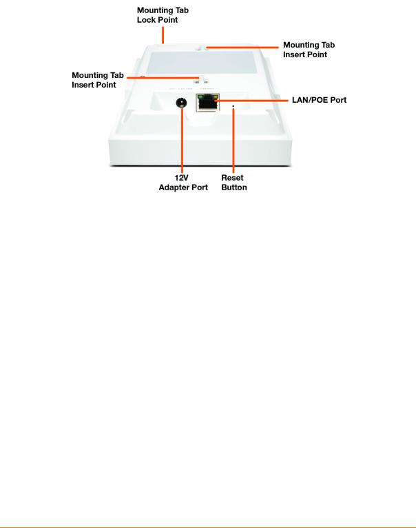
SonicWave 231c Ports and LEDs
The back of SonicWave 231c provides a LAN/POE port where the PoE Ethernet cable connects the access point with the PoE injector or PoE-enabled switch, which connects to your SonicWall network security appliance.
A 12V power connection is also provided on the back of the unit, where you can plug in a 12V adapter (sold separately) to power the device.
SonicWave 231c Back
When the access point is installed, the back panel is attached to the ceiling or to a wall or other flat surface.
SonicWall SonicWave Deployment Guide |
|
8 |
|
||
Hardware Overview |
|
|
|
|
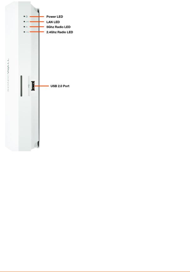
The side panel of the SonicWave 231c has the LED indicators and the USB port.
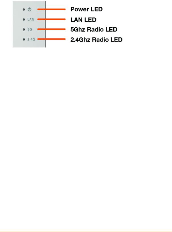
SonicWave 231c LEDs
You can insert a 3G/4G USB modem into the USB port to create a mobile wireless (MiFi) hotspot. See the SonicOS 6.5 Connectivity administration documentation for information about the MiFi Extender feature. You can also use the USB port with a USB security clamp.
SonicWave 231c LED Activity
The SonicWave 231c LEDs provide essential status information about the access point.
Power LED
LED Color |
Description |
|
|
Off |
No power |
|
|
Blue |
Power is on |
|
|
LAN LED
LED Color |
Description |
|
|
Off |
No link |
|
|
Solid Yellow |
Link established at 1 Gbps |
|
|
Blinking Yellow |
Active traffic at 1 Gbps |
|
|
SonicWall SonicWave Deployment Guide |
|
9 |
|
||
Hardware Overview |
|
|
|
|

LAN LED
LED Color |
Description |
|
|
Solid Green |
Link established at 100 Mbps or 10 Mbps |
|
|
Blinking Green |
Active traffic at 100 Mbps or 10 Mbps |
|
|
5 GHz Radio LED
LED Color |
Description |
|
|
|
|
Off |
5 |
GHz radio is off |
|
|
|
Solid Green |
5 |
GHz radio is on |
|
|
|
Blinking Green |
Active traffic on 5 GHz radio |
|
|
|
|
2.4 GHz Radio LED
LED Color |
Description |
|
|
|
|
Off |
2.4 |
GHz radio is off |
|
|
|
Solid Green |
2.4 |
GHz radio is on |
|
|
|
Blinking Green |
Active traffic on 2.4 GHz radio |
|
|
|
|
LED Pattern During Firmware or SafeMode Bootup
LEDs LED Color Description
LAN |
Green - Heartbeat |
5 GHz Radio |
Green - Heartbeat |
2.4 GHz Radio |
Green - Heartbeat |
The three LEDs blink simultaneously in a heartbeat pattern while booting is in progress:
On - On - Off
LED Pattern for Reset Button Hold Durations
LEDs |
LED Color |
Description |
|
|
|
|
|
LAN |
Blinking Green |
ThethreeLEDsblink simultaneously ata slow |
|
|
|
or medium rate: |
|
5 GHz Radio |
Blinking Green |
||
• Slow blink – Press Reset button 3 sec |
|||
|
|
||
2.4 GHz Radio |
Blinking Green |
||
• Med blink – Press Reset button 8 sec |
|||
|
|
||
|
|
|
LED Pattern in SafeMode
LEDs LED Color Description
LAN |
Green - Flow |
5 GHz Radio |
Green - Flow |
2.4 GHz Radio |
Green - Flow |
The three LEDs turn on serially (one by one)
and then turn off serially in a flow pattern
while the <Short Product Name> is in
SafeMode.
NOTE: The LEDs are disabled by default. You can enable them in the SonicWave provisioning profile or individual SonicWave entry in SonicOS on the firewall.
SonicWall SonicWave Deployment Guide |
|
10 |
|
||
Hardware Overview |
|
|
|
|
SonicWave 224w Hardware Overview
SonicWave 224w Product Description
Distinguishing features of the SonicWave 224w include:
•Wall-mount design / mount on ceiling or wall
•2 x 2 MU-MIMO
•Ethernet: 3 x 10/100/1000, 2x 10/100/1000 pass-through ports supporting PoE
•802.3at PoE power supply with optional 12 V adapter
•PoE output: 802.3af
•Accessible (after mounting) reset button
SonicWave 224w
SonicWave 224w Hardware Components
Component |
Description |
|
|
2.4GHz and 5GHz radios |
Dual radios provide: |
|
• 802.11b/g/n/ac |
|
• DFS (Dynamic Frequency Selection) |
|
SonicWave 224w complies with FCC rules to detect and avoid interfering |
|
with radar signals in DFS bands. |
|
• 2x2 11n + 2x2 11ac MU-MIMO |
|
|
1GbE LAN ports |
3 Ethernet 10/100/1000 LAN ports for wired connections to a SonicWall |
|
network security appliance |
|
|
Pass through LAN port |
1 Ethernet 10/100/1000 pass through LAN port pair for a separate network |
|
connection from the same wall jack |
|
|
LAN PoE Out port |
1 LAN PoE Out port for 802.3af device |
|
|
Flash memory |
256 MB NAND Flash |
|
|
DDR Memory |
512 MB DDR3-1600MHz |
|
|
Antennas |
4 internal (2.4Ghz x 2 / 5Ghz x 2) |
|
|
Power source |
802.3at PoE (standard, PoE device sold separately) |
|
Optional DC 12V power adapter, sold separately |
|
|
Chassis |
Rectangle 122mm x 188mm x 18mm |
|
|
Kensington security slot |
For use with a Kensington locking cable to prevent theft |
|
|
Operating temperature |
0° to 40°C |
|
|
SonicWall SonicWave Deployment Guide |
|
11 |
|
||
Hardware Overview |
|
|
|
|
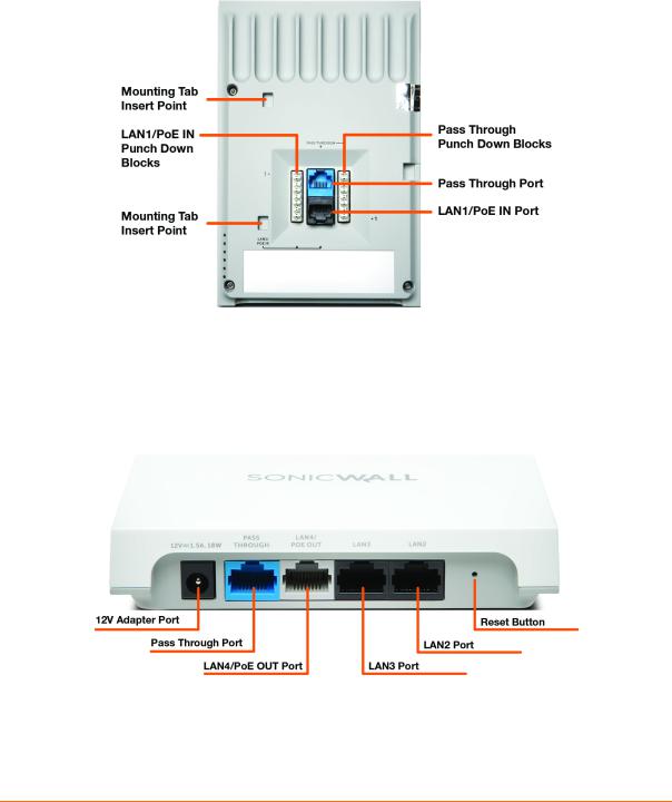
SonicWave 224w Ports and LEDs
The SonicWave 224w is a “wall jack” access point. The back of the device provides two LAN ports, a LAN1/PoE IN port where the PoE Ethernet cable connects the access point with the PoE injector or PoE-enabled switch, and one port of the LAN Pass Through port pair.
Punch down blocks are also provided for both LAN1/PoE IN and Pass Through. For the LAN1/PoE IN connection, pin 1 of the Ethernet connector connects to the top left punch down block (labeled as 1>). For the Pass Through connection, pin 1 of the Ethernet connector connects to the bottom right punch-down block (labeled as <1). The rest of the pins are laid out in sequential order from 1-8.
SonicWave 224w Back
When the access point is installed, the back panel is attached to the wall or to a junction box.
The blue PassThrough port is directlyconnected to the bluePassThrough port on the bottom edge ofthe unit. Neither of these ports access any functionality in the SonicWave 224w, but they provide a way for you to connect to a second network available in the same wall jack that provides your PoE-enabled network connection.
224w Ports on Bottom Edge
Other ports on the bottom edge of the SonicWave 224w include a power connection where you can plug in a 12V adapter (optional),and the LAN4/PoEOUT portwhich providespoweroverEthernet foran802.3afdevice, such as an IP camera.
The LAN2 and LAN3 ports provide a way for you to connect directly to the SonicWave 224w over Ethernet for access to the Internet or internal networks via the SonicWall firewall that is connected to the SonicWave 224w.
The side panel of the SonicWave 224w has the LED indicators.
SonicWall SonicWave Deployment Guide |
|
12 |
|
||
Hardware Overview |
|
|
|
|

SonicWave 224 LEDs
For information about the LEDs, see the SonicWave 224w LED Activity section.
SonicWave 224w LED Activity
The SonicWave 224w LEDs provide essential status information about the access point.
Power LED
LED Color |
Description |
|
|
Off |
No power |
|
|
Blue |
Power source is AT (802.3at) |
|
|
Yellow |
Power source is not AT |
|
|
LAN LED
LED Color |
Description |
|
|
Off |
No link |
|
|
Solid Yellow |
Link established at 1 Gbps |
|
|
Blinking Yellow |
Active traffic at 1 Gbps |
|
|
Solid Green |
Link established at 100 Mbps or 10 Mbps |
|
|
Blinking Green |
Active traffic at 100 Mbps or 10 Mbps |
|
|
5 GHz Radio LED
LED Color |
Description |
|
|
|
|
Off |
5 |
GHz radio is off |
|
|
|
Solid Green |
5 |
GHz radio is on |
|
|
|
Blinking Green |
Active traffic on 5 GHz radio |
|
|
|
|
2.4 GHz Radio LED
LED Color |
Description |
|
|
|
|
Off |
2.4 |
GHz radio is off |
|
|
|
Solid Green |
2.4 |
GHz radio is on |
|
|
|
Blinking Green |
Active traffic on 2.4 GHz radio |
|
|
|
|
SonicWall SonicWave Deployment Guide |
|
13 |
|
||
Hardware Overview |
|
|
|
|

PoE OUT LED
LED Color |
Description |
|
|
Off |
PoE power output is disabled |
|
|
Solid Green |
PoE power output is enabled |
|
|
LED Pattern During Firmware or SafeMode Bootup
LEDs LED Color Description
LAN |
Green - Heartbeat |
5 GHz Radio |
Green - Heartbeat |
2.4 GHz Radio |
Green - Heartbeat |
The three LEDs blink simultaneously in a heartbeat pattern while booting is in progress:
On - On - Off
LED Pattern for Reset Button Hold Durations
LEDs |
LED Color |
Description |
|
|
|
|
|
LAN |
Blinking Green |
ThethreeLEDsblink simultaneously ata slow |
|
|
|
or medium rate: |
|
5 GHz Radio |
Blinking Green |
||
• Slow blink – Press Reset button 3 sec |
|||
|
|
||
2.4 GHz Radio |
Blinking Green |
||
• Med blink – Press Reset button 8 sec |
|||
|
|
||
|
|
|
LED Pattern in SafeMode
LEDs LED Color Description
LAN |
Green - Flow |
5 GHz Radio |
Green - Flow |
2.4 GHz Radio |
Green - Flow |
The three LEDs turn on serially (one by one) and then turn off serially in a flow pattern while the SonicWave 224w is in SafeMode.
NOTE: The LEDs are disabled by default. You can enable them in the SonicWave provisioning profile or individual SonicWave entry in SonicOS on the firewall.
SonicWall SonicWave Deployment Guide |
|
14 |
|
||
Hardware Overview |
|
|
|
|
SonicWave 231o Hardware Overview
SonicWave 231o Product Description
Because this product has unique market and functionality, the SonicWave 231o requires specially trained professionals to configure and install it. Also, according to FCC rules (similar rules in other regulatory domains), you are required to consult with an experienced professional RF installer/dealer/technician to conduct the installation, conform to the regulation, and correct the interference from the standard industry measures. The FCC requires you to be notified that any changes or modifications made to the device, that are not expressly approved by SonicWall, could void your authority to operate the equipment. A professional installer is responsible for the proper installation and configuration of the outdoor SonicWave. The installer needs to understandandprepareforoperatingnearanyTerminalDopplerWeatherRadar(TDWR)locationsbasedonthe FCC Memorandum and comply with all its requirements. The professional installer needs to choose the correct antenna type and its gain should be so chosen that the equivalent isotropically radiated power (EIRP) is not more than that required for successful communication to ensure the reduction of potential radio interference with other users. The professional installer must also properly select the current country of operation from the SonicWall configuration interface. Incorrectly entering the country of operation could result in illegal operation and might cause harmful interference to other systems.
Distinguishing features of the SonicWave 231o include:
•For outdoor application, licensed installer required.
•2 x 2 MU-MIMO
•NEMA mounting kit / 4 external, omni-directional antennas.
•Ethernet: 1 x 10/100/1000 auto-sensing RJ-45
•PoE in: 802.11af
SonicWave 231o Top
SonicWave 231o Hardware Components
Component |
Description |
|
|
2.4GHz and 5GHz radios |
Dual radios provide: |
|
• 802.11b/g/n/ac |
|
• DFS (Dynamic Frequency Selection) |
|
SonicWave 231o complies with FCC rules to detect and avoid interfering with radar |
|
signals in DFS bands. |
|
• 2x2 11n + 2x2 11ac wave 2 MU-MIMO |
|
|
1GbE LAN port |
1 Ethernet 10/100/1000 LAN port for wired connection to a SonicWall network security |
|
appliance |
|
|
Flash memory |
256 MB NAND Flash |
|
|
DDR Memory |
512 MB DDR3-1600MHz |
|
|
SonicWall SonicWave Deployment Guide |
|
15 |
|
||
Hardware Overview |
|
|
|
|

SonicWave 231o Hardware Components
Component |
Description |
|
|
Scanning radio |
Dedicated third scanning radio |
|
|
Antennas |
4 external Omni-Antenna (2.4Ghz x 2 / 5Ghz x 2) |
|
1 internal antenna for scanning radio |
|
|
Power source |
802.3af PoE (standard, PoE device sold separately) |
|
|
Chassis |
Rectangle 122mm x 188mm x 18mm |
|
Plenum rated |
|
|
Operating temperature |
-30° to 60°C |
|
|
NOTE: The SonicWave 231o enclosure is IP67 compliant with components supplied with the product and when installed as instructed.
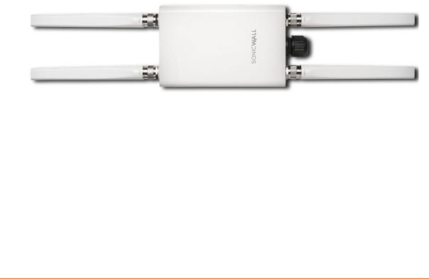
SonicWave 231o Antenna Connectors and LAN(PoE) Port
Four antenna ports on the ends of the SonicWave 231o provide connection points for the two 5GHz antennas and two 2.4GHz antennas.
The SonicWave 231o provides one LAN(PoE) port for connecting to the PoE injector or PoE-enabled switch and to your SonicWall network security appliance. You can also use a SonicWall PoE-enabled security appliance to provide PoE from the appliance itself.
SonicWave 231o Bottom
SonicWall SonicWave Deployment Guide |
|
16 |
|
||
Hardware Overview |
|
|
|
|
The bottom of the SonicWave 231o has four slots for inserting the pegs on the mounting bracket, and a threadedholeforthemountingbracketlockingscrew.Thegroundconnectionpointisalsoonthebottomofthe device.
SonicWave 231o LEDs
The side panel of the SonicWave 231o has the LED indicators.
For information about the LEDs, see the SonicWave 224w LED Activity section.
SonicWave 231o LED Activity
The SonicWave 231o LEDs provide essential status information about the access point.
Power LED
LED Color |
Description |
|
|
Off |
No power |
|
|
Blue |
Power is on |
|
|
LAN LED
LED Color |
Description |
|
|
Off |
No link |
|
|
Solid Yellow |
Link established at 1 Gbps |
|
|
Blinking Yellow |
Active traffic at 1 Gbps |
|
|
Solid Green |
Link established at 100 Mbps or 10 Mbps |
|
|
Blinking Green |
Active traffic at 100 Mbps or 10 Mbps |
|
|
5 GHz Radio LED
LED Color |
Description |
|
|
|
|
Off |
5 |
GHz radio is off |
|
|
|
Solid Green |
5 |
GHz radio is on |
|
|
|
Blinking Green |
Active traffic on 5 GHz radio |
|
|
|
|
2.4 GHz Radio LED
LED Color |
Description |
|
|
|
|
Off |
2.4 |
GHz radio is off |
|
|
|
Solid Green |
2.4 |
GHz radio is on |
|
|
|
Blinking Green |
Active traffic on 2.4 GHz radio |
|
|
|
|
SonicWall SonicWave Deployment Guide |
|
17 |
|
||
Hardware Overview |
|
|
|
|

LED Pattern During Firmware Bootup
LEDs |
LED Color |
Description |
|
|
|
|
|
LAN |
Green - Heartbeat |
The three LEDs blink simultaneously in a heartbeat |
|
|
|
pattern while booting is in progress: |
|
5 GHz Radio |
Green - Heartbeat |
||
On - On - Off |
|||
|
|
||
2.4 GHz Radio |
Green - Heartbeat |
|
|
|
|
|
NOTE: The LEDs are disabled by default. You can enable them in the SonicWave provisioning profile or individual SonicWave entry in SonicOS on the firewall.
SonicWall SonicWave Deployment Guide |
|
18 |
|
||
Hardware Overview |
|
|
|
|

SonicWave 432e and 432i
Hardware Overview
SonicWave 432e and 432i Product Description
The SonicWave 432e provides physical layer enhancements over earlier SonicWall access points for higher throughput with a maximum data rate of 1.3 Gbps. To achieve this, the SonicWave 432e uses:
•More antennas—three antennas for the 5 GHz radio, and three more for the 2.4 GHz radio
•Wider channels—80 MHz-wide channels for the 802.11ac radio module, while continuing to support 20/40 MHz channels. This allows for dynamic per packet negotiation of channel widths so that when there is interference, the SonicWave can temporarily fall back to 40 or 20MHz channels.
•Morespatialstreams—4x4multiple-inputandmultiple-output, (MIMO)forthe802.11acradiomodule, where the capacity of a radio link is multiplied using multipath propagation.
Salient features of the SonicWave 432e and 432i include:
•For indoor use with wall / ceiling mount
•4 x 4 MU-MIMO
•432e with external high-gain antennas (4 x 4) and 432i with 8 internal antennas
•LAN1 supports up to 2.5 GbE and 802.3at PoE
•LAN2 supports 10/100/1000 MbE
•USB 2.0
•Ethernet console port (RJ 45)
SonicWall SonicWave Deployment Guide |
|
19 |
|
||
Hardware Overview |
|
|
|
|
SonicWave 432e and SonicWave 432i
Available Ports/Status LEDs
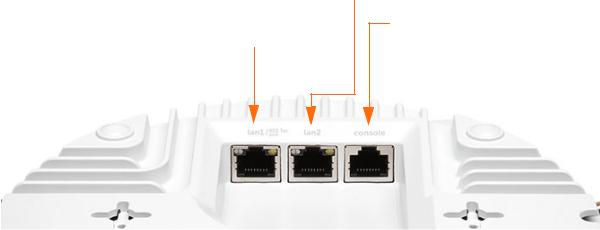
Available Ports
LAN1/PoE port.
Provides Ethernet and Power over Ethernet (PoE)
LAN2 port.
Provides an additional Ethernet connection. Refer to the SonicOS Connectivity Administration documentation for use cases.
Console port.
Provides a management connection using RJ45 to DB9 cable (for command line
|
|
|
|
|
|
|
|
|
|
|
|
|
|
|
SonicWall SonicWave Deployment Guide |
|
20 |
|
|
|||||||
|
|
|
|
|
|
Hardware Overview |
|
|
|
|
|
|
|
|
|
|
Status LEDs
LED (5G) |
|
LED (2.4G) |
||||||
- On (solid green, 5 GHz radio link) |
|
|
- On (solid green, 2.4 GHz radio link) |
|||||
- Blinking green (5 GHz radio activity) |
|
|
- Blinking (2.4 GHz radio activity) |
|||||
LED (lan1) |
|
|
LED (Tool) |
|||||
- On (solid yellow or green, Ethernet link) |
|
|
- On (solid yellow, error) |
|||||
- Blinking yellow (2.5G Ethernet activity) |
|
|
- Blinking (safe mode) |
|||||
- Blinking green (1G/100M Ethernet activity) |
|
|
|
|
|
|||
LED (lan2) |
|
|
LED (Power) |
|||||
- On (solid yellow or green, Ethernet link) |
|
|
- On (solid blue, power) |
|||||
- Blinking yellow (1G Ethernet activity) |
|
|
- Blinking (booting/FW upgrade) |
|||||
- Blinking green (10/100M Ethernet activity) |
|
|
|
|
|
|||
|
|
|
|
|
|
|
|
|
|
|
|
|
|
|
|
|
|
|
|
|
|
|
|
|
|
|
|
|
|
|
|
|
|
|
|
SonicWall SonicWave Deployment Guide |
|
21 |
|
||
Hardware Overview |
|
|
|
|

SonicWave 432o Hardware Overview
SonicWave 432o Product Description
The SonicWave 432o extends your wireless LAN past the traditional boundaries of indoor locations. With state of the art design and construction, it is resistant to harsh outdoor environments and extreme temperature changes. The unit is designed specifically for outdoor use and can be attached to either a pole or wall. WaterproofconnectorsaresuppliedtoensurewatertightsealsforconnectingtheEthernetcablestothedevice. The SonicWave 432o also provides physical layer enhancements for higher throughput with a maximum data rate of 1.3 Gbps. To achieve this, the SonicWave 432o uses:
•More antennas—four antennas for the 5 GHz radio, and four more for the 2.4 GHz radio
•Wider channels—80 MHz-wide channels for the 802.11ac radio module, while continuing to support 20/40 MHz channels. This allows for dynamic per packet negotiation of channel widths so that when there is interference, the SonicWave can temporarily fall back to 40 or 20MHz channels.
•Morespatialstreams—4x4multiple-inputandmultiple-output, (MIMO)forthe802.11acradiomodule, where the capacity of a radio link is multiplied using multipath propagation.
Because of potential EMI issues, professional installation by a properly licsened specialist is required for the
SonicWave 432o.
Distinguishing features of the SonicWave 432o include:
•Antennas: 8 N-type dipole
•4 x 4 MU-MIMO
•Ethernet: 1 x 10/100/1000 and 1 x 10/100/1000/2.5 GbE
•PoE: 802.3at in; 802.3af out
•Ethernet console port (RJ5)
SonicWall SonicWave Deployment Guide |
|
22 |
|
||
Hardware Overview |
|
|
|
|

SonicWave 432o Available Ports/Status LEDs
Available Ports
lan1/PoE in port.
ProvidesEthernetandPower over Ethernet (PoE)
Status LEDs
LED (5G)
- On (solid green, 5 GHz radio link) - Blinking green (5 GHz radio activity)
LED (2.4G)
- On (solid green, 2.4 GHz radio link) - Blinking (2.4 GHz radio activity)
LED (lan2)
-On (solid yellow or green, Ethernet link)
-Blinking yellow (1G Ethernet activity)
-Blinking green (10/100M Ethernet
activity) LED (lan1)
-On (solid yellow or green, Ethernet link)
-Blinking yellow (2.5G Ethernet activity)
- Blinking green (1G/100M Ethernet activity)
LED (Power)
- On (solid blue, power)
- Blinking (booting/FW upgrade) LED (safe mode)
-On (solid blue, power) with 4
-Blinking (green)
lan2/PSE out port.
Provides an additional Ethernet connection. Refer to the SonicOS Connectivity Administration

 console port.
Provides a management connectionusingtheSonicWall console cable (RJ45 to DB9)
SonicWall SonicWave Deployment Guide |
|
23 |
|
||
Hardware Overview |
|
|
|
|

2
Product Specifications
SonicWave access point specifications are presented here:
•SonicWave 200 Series Specifications
•SonicWave 400 Series Specifications
SonicWall SonicWave Deployment Guide |
|
24 |
|
||
Product Specifications |
|
|
|
|

SonicWave 200 Series Specifications
Hardware Specifications
Specification |
SonicWave 231c |
SonicWave 224w |
SonicWave 231o |
|
|
|
|
|
|
Location |
Ceiling |
Wall |
Outdoor |
|
|
|
|
|
|
Radio |
|
2x2 802.11ac Wave 2 |
|
|
|
|
|
|
|
Dedicated 3rd scanning radio |
Yes |
No |
Yes |
|
|
|
|
|
|
USB 2.0 |
Yes |
No |
No |
|
|
|
|
|
|
Bluetooth Low Energy (BLE) radio |
Yes |
Yes |
Yes |
|
|
|
|
|
|
AntennaType |
Internal |
Internal |
Omni-Antenna |
|
|
|
|
|
|
Dimensions |
118mmx214mmx34mm |
122mmx188mmx18mm |
190mmx120mmx42mm |
|
|
|
|
|
|
Shipping dimension |
150mmx240mmx73mm |
150mmx240mmx73mm |
265mmx450mmx78mm |
|
|
|
|
|
|
Unit weight |
0.4 kg |
0.4 kg |
0.7 kg |
|
|
|
|
|
|
WEEE weight |
0.7 kg |
0.7 kg |
2.0 kg |
|
|
|
|
|
|
Shipping weight |
0.7 kg |
0.7 kg |
2.0 kg |
|
|
|
|
|
|
|
802.3af PoE (standard) |
802.3at PoE (standard, sold |
802.3af POE |
|
PoE |
|
separately) |
|
|
|
|
|
||
DC 12V adapter (optional) |
DC 12V adapter (optional) |
(PoE sold separately) |
||
|
||||
|
|
|
|
|
Maximum power consumption (W) |
12W |
12W |
12W |
|
|
|
|
|
|
Status Indicator |
4 |
5 |
4 |
|
|
|
|
|
|
Wired network ports |
1 x 10/100/1000 auto-sensing |
3 x 10/100/1000, 2x |
1 x 10/100/1000 auto-sensing |
|
|
RJ-45 |
10/100/1000, PoE Pass |
RJ-45 |
|
|
|
through, 1 LAN PoE Out |
|
|
|
|
|
||
Accessories included |
Ceiling/wall mounting kit |
NEMA 4x Mounting kit and |
||
|
|
|
external antennas |
|
|
|
|
|
|
Virtual access points |
|
Up to 8 per access point. |
|
|
|
|
|
|
|
Chassis |
|
Rectangle |
|
|
|
|
|
|
|
Standards and Compliance
Standard |
SonicWave 231c |
SonicWave 224w |
SonicWave 231o |
|
|
|
|
IEEE Standard |
|
802.11a/b/g/n/ac |
|
|
|
||
Compliance |
IEEE802.11a,IEEE802.11b,IEEE802.11g,IEEE802.11n,IEEE802.11ac,IEEE802.11e,IEEE802.11i, |
||
|
IEEE 802.3at, IEEE 802.3bz, WPA, TKIP, AES, IEEE 802.11r, IEEE 802.11k, IEEE 802.11v, IEEE 802.11w |
||
|
|
|
|
Plenum rated |
Yes |
No |
No |
|
|
|
|
Regulatory |
|
FCC, IC/ISED, CE, RCM, NCC, TELEC, KCC |
|
|
|
|
|
Safety |
|
UL, cUL, TUV-GS, CB, UL Mexico CoC |
|
|
|
|
|
MIMO |
|
MU-MIMO |
|
|
|
|
|
Max/Recommended connected |
|
128/30 |
|
clients per radio |
|
|
|
|
|
|
|
Environmental
Specification |
SonicWave 231c |
SonicWave 224w |
SonicWave 231o |
|
|
|
|
Temperature Range |
0o to 40oC |
0o to 40oC |
-30o to 60oC |
Humidity |
0% - 95%, typical |
0% - 95%, typical |
5% - 90%, typical |
|
|
|
|
SonicWall SonicWave Deployment Guide |
|
25 |
|
||
Product Specifications |
|
|
|
|

Radio Specifications
Specification |
SonicWave 231c |
SonicWave 224w |
SonicWave 231o |
|
|
|
|
Radios |
3 radios: 5GHz, 2.4GHz and |
2 radios: 5GHz and 2.4GHz |
3 radios: 5GHz, 2.4GHz and |
|
security radio |
|
security radio |
|
|
|
|
Frequency bands |
|
IEEE 802.11 b/g/n: 2.412-2.484 GHz; |
|
|
IEEE 802.11a/n/ac: 5.150-5.250 GHz (UNII-1), 5.250-5.350 GHz (UNII-2), 5.470-5.600, |
||
|
5.660-5.725 GHz (UNII-2e), 5.725-5.825 GHz (UNII-3) |
||
|
|
|
|
Operating channels* |
|
2.4GHz channels: 1-13; |
|
|
5 GHz channels: 36-64, 100-140, 149-165 |
||
|
|
||
Transmit output power* |
Based on the regulatory domain product is installed in and specified by the sytem administrator. |
||
|
|
|
|
Transmit power control* |
|
Supported. |
|
|
|
|
|
Data rates supported |
|
867 Mbps for 5 GHz radio |
|
|
|
400 Mbps for 2.4 GHz radio |
|
|
|
||
Modulation technology spectrum |
802.11ac: Orthogonal Frequency Division Multiplexing (OFDM) |
||
|
|
|
|
* Subject to country regulations. |
|
|
|
Security |
|
|
|
Specification |
SonicWave 231c |
SonicWave 224w |
SonicWave 231o |
|
|
||
Data encryption |
WPA2; IPSec. 802.11i, WPA; 64/128/152-bit WEP, TKIP, AES, SSL VPN** |
||
|
|
|
|
**When used with SonicWall Secure Remote Series appliance. |
|
|
|
Authentication |
|
|
|
Specification |
SonicWave 231c |
SonicWave 224w |
SonicWave 231o |
|
|
|
|
Authentication |
|
RADIUS, Active Directory, Single Sign-On (SSO) |
|
|
|
|
|
SonicWall SonicWave Deployment Guide |
|
26 |
|
||
Product Specifications |
|
|
|
|

SonicWave 400 Series Specifications
Hardware Specifications
Specification |
SonicWave 432e |
SonicWave 432i |
SonicWave 432o |
|
|
|
|
Location |
Indoor |
Indoor |
Outdoor |
|
|
|
|
Dimensions |
8.5(D) x 2.0(H) in |
8.5 (D) x 2.0 (H) in |
9.5(W)x9.3(D)x2.4(H)in |
|
21.6(D) x 5.1(H) cm |
21.6(D)x 5.1(H) cm |
24.1(W)x23.6(D)x6.1(H) cm |
|
|
|
|
Weight |
1.1 kg / 2.5 lbs |
1.0 kg / 2.2 lbs |
2.2 kg /4.9 lbs |
|
|
|
|
WEEE weight |
1.4 kg / 3.1 lbs |
1.2 kg / 2.6 lbs |
4.1 kg / 9.1 lbs |
|
|
|
|
Shipping weight |
1.7 kg / 3.8 lbs |
1.5kg / 3.3 lb |
4.7 kg / 10.4 lbs |
|
|
|
|
PoE |
|
802.3at |
|
|
|
|
|
Maximum power consumption (W) |
18.8W |
18.8W |
21.2W |
|
|
|
|
Status Indicators |
|
Six (6) LED (WLAN/Link)(LAN/Link) Power, Test |
|
|
|
||
Wired network ports |
(1) 10/100/1000 auto-sensing RJ-45 for Ethernet (PoE): (1) 100/1000/2.5 GBE auto-sensing, RJ-45 |
||
|
for Ethernet; (1) RJ-45 console; USB 2.0 (except 432o) |
||
|
|
|
|
Accessories included |
|
Wall / ceiling mount kit |
|
|
|
|
|
Virtual access points |
|
Up to 8 per access point. |
|
|
|
|
|
Chassis |
|
UL 1024 plenum rated |
|
|
|
|
|
Standards and Compliance
Standard |
SonicWave 432e |
SonicWave 432i |
SonicWave 432o |
|
|
|
|
IEEE Standard |
|
802.11a/b/g/n/ac Wave 2 |
|
|
|
||
Compliance |
IEEE802.11a,IEEE802.11b,IEEE802.11g,IEEE802.11n,IEEE802.11ac,IEEE802.11e,IEEE802.11i, |
||
|
IEEE802.3at, IEEE 802.3bz, WPA, TKIP, AES, IEEE 802.11r, IEEE 802.11k, IEEE 802.11v, IEEE 802.11w |
||
|
|
||
Regulatory |
FCC/ICES Class B, CE, RCM/ACMA, VCCI Class B, TELEC, BSMI, NCC, MSIP, ANATEL, Customs Union |
||
|
|
RoHs (Europe/China), WEEE |
|
|
|
||
Safety |
UL, cUL, TUV/GS, CB, CE, BSMI, Mexico CoC, Custom Union |
||
|
|
|
|
MIMO |
|
MU-MIMO 4x4 (4 streams) |
|
|
|
|
|
Max/Recommended connected |
|
128/30 |
|
clients per radio |
|
|
|
|
|
|
|
Enviromental
Specification |
SonicWave 432e |
SonicWave 432i |
SonicWave 432o |
|
|
|
|
Temperature Range |
32o to 104oF, 0o to 40oC |
-40o to 140oF |
|
|
|
|
-40o to 60oC |
Humidity |
|
10 — 95%, non-condensing |
|
|
|
|
|
SonicWall SonicWave Deployment Guide |
|
27 |
|
||
Product Specifications |
|
|
|
|

Radio Specifications
Specification |
SonicWave 432e |
SonicWave 432i |
SonicWave 432o |
|
|
||
Radios |
Dual: 4x4 11n + 4x4 11ac MU-MIMO; Dedicated third scaning radio; Bluetooth Low Energy Radio |
||
|
|
|
|
Frequency bands |
|
802.11a: 5.180 – 5.825 GHz |
|
|
|
802.11b/g: 2.412 – 2.472 GHz |
|
|
|
802.11n: 2.412 – 2.472 GHz, 5.180 – 5.825 GHz |
|
|
802.11ac: 2.412 – 2.472 GHz, 5.180 – 5.825 GHz |
||
|
|
||
Operating channels* |
802.11a: US and Canada 12. Europe 11. Japan 4. Singapore 4. Taiwan 4. |
||
|
802.11b/g: US and Canada 1-11. Europe 1-13. Japan 1-14 (14-802.11b only) |
||
|
802.11n (2.4 GHz): US and Canada 1-11. Europe 1-13. Japan 1-13. |
||
|
802.11n (5 GHz): US and Canada 36-48/149-165. Europe 36-48. Japan 36-48. Spain 36-48/52-64 |
||
|
802.11ac: US and Canada 36-48/149-165. Europe 36-48. Japan 36-48. Spain 36-48/52-64. |
||
|
|
||
Transmit output power* |
Based on the regulatory domain product is installed in and specified by the sytem administrator. |
||
|
|
|
|
Transmit power control* |
|
Supported. |
|
|
|
||
Data rates supported |
802.11a: 6, 9, 12, 18, 24, 36, 48, 54 Mbps per channel |
||
|
|
802.11b: 1, 2, 5.5, 11 Mbps per channel |
|
|
802.11g: 6, 9, 12, 18, 24, 36, 48, 54 Mbps per channel |
||
|
802.11n:7.2,14.4,21.7,28.9,43.3,57.8,65,72.2,86.7,96.3,15,30,45,6090,120,135,150,180, |
||
|
200, 65, 97.5, 130, 195, 260, 292.5, 325, 390, 433.3, 65, 130, 495, 260, 390, 520, 585, 650, 780, |
||
|
|
866.7, 1040, 1170, 1300, 1560, 1733.4 Mbps |
|
|
|
||
Modulation technology spectrum |
802.11a: Orthogonal Frequency Division Multiplexing (OFDM) |
||
|
802.11b: Direct Sequence Spread Spectrum (DSSS) |
||
|
802.11g: Orthogonal Frequency Division Multiplexing (OFDM)/Direct Sequence Spread Spectrum |
||
|
|
(DSS) |
|
|
802.11n: Orthogonal Frequency Division Multiplexing (OFDM) |
||
|
802.11ac: Orthogonal Frequency Division Multiplexing (OFDM) |
||
|
|
|
|
* Subject to country regulations |
|
|
|
Security |
|
|
|
Specification |
SonicWave 432e |
SonicWave 432i |
SonicWave 432o |
|
|
||
Data encryption |
WPA2; IPSec**. 802.11i, WPA, 64/128/152-bit WEP, TKIP, AES, SSL VPN*** |
||
|
|
|
|
** When used with a SonicWall firewall |
|
|
|
***When used with SonicWall Secure Mobile Access Series appliance |
|
|
|
Authentication |
|
|
|
Specification |
SonicWave 432e |
SonicWave 432i |
SonicWave 432o |
|
|
|
|
Authentication |
|
RADIUS, Active Directory, single sign-on (SSO) |
|
|
|
|
|
SonicWall SonicWave Deployment Guide |
|
28 |
|
||
Product Specifications |
|
|
|
|

3
Deployment Requirements per Model
SoinicWall wireless access point deployment requirements are presented in the following sections.
Topics:
•SonicWave 231c Deployment Requirements
•SonicWave 224w Deployment Requirements
•SonicWave 231o Deployment Requirements
•SonicWave 432e and 432i Deployment Requirements
•SonicWave 432o Deployment Requirements
SonicWall SonicWave Deployment Guide |
|
29 |
|
||
Deployment Requirements per Model |
|
|
|
|
Loading...