


 Loading...
Hand Held
Welders
Model H520 T/E
Model H530 T/E
Model H540 T/E
I N ST RU CTI ON M A NUA L

TA BLE OF CO NTENTS
IMPORTANT SERVICE INFORMATION . . . . . . . . . . . . . . . . . . . . . . . . . . .3
Important Safeguards . . . . . . . . . . . . . . . . . . . . . . . . . . . . . . . . . . .3
Warnings . . . . . . . . . . . . . . . . . . . . . . . . . . . . . . . . . . . . . . . . . . . . .3
Symbols . . . . . . . . . . . . . . . . . . . . . . . . . . . . . . . . . . . . . . . . . . . . .4
SPECIFICATIONS . . . . . . . . . . . . . . . . . . . . . . . . . . . . . . . . . . . . . . . . . . . .5
IMPORTANT SERVICE LITERATURE . . . . . . . . . . . . . . . . . . . . . . . . . . . .6
Manual Change Information . . . . . . . . . . . . . . . . . . . . . . . . . . . . . .6
UNPACKING AND INSPECTION . . . . . . . . . . . . . . . . . . . . . . . . . . . . . . . .7
Visible Loss or Damage . . . . . . . . . . . . . . . . . . . . . . . . . . . . . . . . .7
Concealed Loss or Damage . . . . . . . . . . . . . . . . . . . . . . . . . . . . . .7
INTRODUCTION . . . . . . . . . . . . . . . . . . . . . . . . . . . . . . . . . . . . . . . . . . . . .8
OVERVIEW OF ULTRASONIC PLASTICS ASSEMBLY . . . . . . . . . . . . . . .8
What is Ultrasonics? . . . . . . . . . . . . . . . . . . . . . . . . . . . . . . . . . . . .8
Principal of Ultrasonic Assembly . . . . . . . . . . . . . . . . . . . . . . . . . .8
Ultrasonic Hand Held Welders . . . . . . . . . . . . . . . . . . . . . . . . . . . .8
GLOSSARY OF ULTRASONIC TERMS . . . . . . . . . . . . . . . . . . . . . . . . . .10
INSTALLATION AND SET UP . . . . . . . . . . . . . . . . . . . . . . . . . . . . . . . . . .11
Electrical Power Requirements . . . . . . . . . . . . . . . . . . . . . . . . . . .11
Setting Up . . . . . . . . . . . . . . . . . . . . . . . . . . . . . . . . . . . . . . . . . . .11
Electrical Connections . . . . . . . . . . . . . . . . . . . . . . . . . . . . . . . . .11
Cable Connections . . . . . . . . . . . . . . . . . . . . . . . . . . . . . . . . . . . .12
Key Components . . . . . . . . . . . . . . . . . . . . . . . . . . . . . . . . . . . . .13
Tip Assembly (CV53/55) . . . . . . . . . . . . . . . . . . . . . . . . . . . . . . . .14
Tip Replacement (CV53/55) . . . . . . . . . . . . . . . . . . . . . . . . . . . . .14
Horn Assembly (CVG54 Only) . . . . . . . . . . . . . . . . . . . . . . . . . . . .14
Tip Replacement (CVG54) . . . . . . . . . . . . . . . . . . . . . . . . . . . . . . .15
Tip Specifications . . . . . . . . . . . . . . . . . . . . . . . . . . . . . . . . . . . . .16
Options . . . . . . . . . . . . . . . . . . . . . . . . . . . . . . . . . . . . . . . . . . . . .17
Sonics & Materials, Inc.
Corporate Headquarters
53 Church Hill Road • Newtown, CT 06470 USA 203.270.4600 • 800.745.1105 • 203.270.4610 fax www.sonics.com • info@sonics.com
Information contained in this manual is subject to change without notice. Sonics & Materials, Inc. is not responsible for any typographic errors.
© Sonics & Materials, Inc. 2012 |
Printed in U.S.A. |
Part No. 381-0035 |
|||
|
|
|
|
Rev AC 03 8/12 |
|
|
|
|
• • • • • • • • • • • • • • • • • • • • • • • • • • • • • • • • • • • • • • • • • • • • • • • • • • • • • • • • • • • • • • • • • • • • • • • • • • • • • • • • • • • • • • • • • • • • • • • • • • • • • • • • • • • • |
||
|
|
|
|||
|
|
|
I NS T RU C T IO N MA NU A L • H AN D H E LD |
W ELD ERS |
1 |
|
|
|
|||
Go To Top Of Document

OPERATING PROCEDURES . . . . . . . . . . . . . . . . . . . . . . . . . . . . . . . . . .19
Front Panel Controls and Indicators . . . . . . . . . . . . . . . . . . . . . . .19
Keying in Parameters . . . . . . . . . . . . . . . . . . . . . . . . . . . . . . . . . .20
Operational Features . . . . . . . . . . . . . . . . . . . . . . . . . . . . . . . . . . .21
Starting up the Welder . . . . . . . . . . . . . . . . . . . . . . . . . . . . . . . . .21
Test Feature . . . . . . . . . . . . . . . . . . . . . . . . . . . . . . . . . . . . . . . . . .21
Ready Screens . . . . . . . . . . . . . . . . . . . . . . . . . . . . . . . . . . . . . . .22
Relationship of Time and Energy Settings . . . . . . . . . . . . . . . . . .23
Time Settings . . . . . . . . . . . . . . . . . . . . . . . . . . . . . . . . . . . . . . . .24
Energy Settings . . . . . . . . . . . . . . . . . . . . . . . . . . . . . . . . . . . . . . .25
Amplitude . . . . . . . . . . . . . . . . . . . . . . . . . . . . . . . . . . . . . . . . . . .25
Frequency Display . . . . . . . . . . . . . . . . . . . . . . . . . . . . . . . . . . . . .25
Overload Protection . . . . . . . . . . . . . . . . . . . . . . . . . . . . . . . . . . .26
Keypad Security . . . . . . . . . . . . . . . . . . . . . . . . . . . . . . . . . . . . . .27
APPLICATIONS – STAKING . . . . . . . . . . . . . . . . . . . . . . . . . . . . . . . . . . .28
Standard Flared Stake . . . . . . . . . . . . . . . . . . . . . . . . . . . . . . . . .28
Spherical Stake . . . . . . . . . . . . . . . . . . . . . . . . . . . . . . . . . . . . . .29
Hollow Stake . . . . . . . . . . . . . . . . . . . . . . . . . . . . . . . . . . . . . . . . .29
Knurled Stake . . . . . . . . . . . . . . . . . . . . . . . . . . . . . . . . . . . . . . . .29
Flush Stake . . . . . . . . . . . . . . . . . . . . . . . . . . . . . . . . . . . . . . . . . .30
APPLICATIONS – SPOT WELDING . . . . . . . . . . . . . . . . . . . . . . . . . . . . .31
Ordering Information . . . . . . . . . . . . . . . . . . . . . . . . . . . . . . . . . . .31
APPLICATIONS – ULTRASONIC INSERTION . . . . . . . . . . . . . . . . . . . . .32
MAINTENANCE . . . . . . . . . . . . . . . . . . . . . . . . . . . . . . . . . . . . . . . . . . . . .34
Cleaning Instructions . . . . . . . . . . . . . . . . . . . . . . . . . . . . . . . . . .34
Repairs / Service . . . . . . . . . . . . . . . . . . . . . . . . . . . . . . . . . . . . . .34
WARRANTY . . . . . . . . . . . . . . . . . . . . . . . . . . . . . . . . . . . . . . . . . . . . . . . .35
Limitation of Warranty . . . . . . . . . . . . . . . . . . . . . . . . . . . . . . . . . .36
APPENDIX . . . . . . . . . . . . . . . . . . . . . . . . . . . . . . . . . . . . . . . . . . . . . . . . .38
• • • • • • • • • • • • • • • • • • • • • • • • • • • • • • • • • • • • • • • • • • • • • • • • • • • • • • • • • • • • • • • • • • • • • • • • • • • • • • • • • • • • • • • • • • • • • • • • • • • • • • • • • • • •
2 |
I NST RUCTIO N MA NU AL • H A N D HE LD WELD E RS |
Go To Top Of Document

IMPORTANT SAFETY IN FORMATIO N
IMPORTANT SAFEGUARDS – READ BEFORE INSTALLING
OR USING THE EQUIPMENT
Your Ultrasonic Equipment has been designed with safety in mind. However, no design can completely protect against improper usage, which may result in bodily injury and/or property damage. For your protection and equipment safeguard, observe the following warnings at all times, read the operating instructions carefully before operating the equipment, and retain this instruction manual for future reference. If the Ultrasonic Equipment is used in a manner contrary to that specified in this instruction manual, the protection
features designed into the unit may be impaired.
WARNINGS
•Make sure the Ultrasonic Power Supply is properly grounded via a 3- prong outlet.
•High voltage is present in the power supply. Do not remove the cover. Refer all servicing to qualified service personnel.
•Never operate the power supply unless it is connected to the hand gun.
•Never secure anything to the front driver, the tip or the horn.
•Never touch a vibrating horn.
•If air-cooling the converter, always use dry compressed air.
•Hearing protection is highly recommended. It is recommended that a sound abating enclosure or ear protection be used when operating the Ultrasonic Processor.
•Do not modify horn configurations.
•Do not affix any device to any portion of the horn.
•Certain plastic materials, when ultrasonically welded, may emit fumes and/or gases hazardous to an operator’s health. Where such materials are processed, proper ventilation of the work station should be provided. If in doubt about the toxicity of your plastic material, contact OSHA, U.S. Department of Labor, or material supplier.
•Maintenance should be performed only by a qualified electronic technician.
•Always turn off the power supply before installing or removing the optional foot switch cable.
•When the hand gun (converter) is on, be sure to isolate it from any/all grounded surfaces (including machine frames) to avoid triggering an overload condition as the system detects an alternate ground path.
• • • • • • • • • • • • • • • • • • • • • • • • • • • • • • • • • • • • • • • • • • • • • • • • • • • • • • • • • • • • • • • • • • • • • • • • • • • • • • • • • • • • • • • • • • • • • • • • • • • • • • • • • • • • E
I NS TR UC T ION M AN U AL • H AN D H ELD WELD E RS |
3 |
Go To Top Of Document

SYMBOLS
Caution, risk of electric shock, hazardous voltage
Caution, risk of danger.
Refer to User Manual.
WARNING or CAUTION
Where you see the alert symbols and/or WARNING or CAUTION heading, strictly follow the
warning instructions to avoid personal injury or equipment failure.
• • • • • • • • • • • • • • • • • • • • • • • • • • • • • • • • • • • • • • • • • • • • • • • • • • • • • • • • • • • • • • • • • • • • • • • • • • • • • • • • • • • • • • • • • • • • • • • • • • • • • • • • • • • •
4 INS TRUCTI ON M ANU AL • H AN D H E LD WE LD E R S
Go To Top Of Document

SP EC IFIC ATIO NS
Power Supply |
|
|
|
|
|
|
|
|
|
Operational Input Voltage |
115/230 V~ +/-10% @ 50/60 Hz |
|
||
|
|
|
|
|
Rated Voltage/Current |
115/230 V~, 5 A max. |
|
||
|
|
|
|
|
Fuse Rating |
F6.3A 250V* |
|
||
|
|
|
|
|
Weight |
13 lbs. (5.9 Kg) |
|
||
|
|
|
|
|
Dimensions |
8.5"H x 13.5"W x 7.5"D |
|
||
|
216 mm x 340 mm x 190 mm |
|
||
|
|
|
|
|
Output Voltage |
1000 V rms (max.) |
|
||
|
|
|
|
|
Output Frequency |
20 KHz (nom.), 30 kHz or 40 KHz |
|
||
|
|
|
|
|
|
|
|
|
|
Converter |
|
CV 55 & CV 53 |
CV 54 |
|
|
|
|
||
Weight |
1.5 lbs. (0.68 Kg) |
1.5 lbs. (0.68 Kg) |
||
|
|
|
||
Dimensions |
7.1" (CV55) or 6.3” L (CV53) x 1.9" Dia. |
6.3" L x 1.9" Dia. |
||
|
(180 or 160 mm x 48.3 mm) (withstandardtip) |
(160 mm x 48.3 mm) (without horn) |
||
|
|
|
||
Horn Materials |
Titanium |
Titanium or aluminum |
||
|
|
|
|
|
|
|
|
|
|
Tip |
|
CV 55 & CV 53 |
CV 54 |
|
|
|
|
|
|
Dimensions |
Standard 1/2" diameter (12.7 mm) |
n/a |
||
|
|
|
|
|
Materials |
Titanium Alloy Ti-6Al-4V |
|
||
|
|
|
|
|
|
|
|
|
|
Environmental |
|
|
|
|
|
|
|
|
|
Pollution Degree |
2 |
|
|
|
|
|
|
|
|
Installation Category |
II |
|
||
|
|
|
|
|
Operating Limits |
Temperature: 41 - 104ºF (5 - 40ºC) |
|
||
|
Relative Humidity 20 - 90% (Non Condensing) |
|||
|
Altitude: 6,651 ft. (2000 m) |
|
||
|
|
|
|
|
Shipping/Storage |
Temperature: 35 -120ºF (2 - 49ºC) |
|
||
|
Relative Humidity 10 - 95% (Non Condensing) |
|||
|
Ambient Pressure Extremes: 40,000 ft. (12,192 m) |
|||
|
|
|
|
|
Restriction of |
|
|
|
|
|
RoHS Compliant |
|
|
|
Hazardous |
|
|
|
|
Substances (ROHS) |
|
Directive 2002/95/EC |
|
|
|
|
|
|
|
|
|
|
|
|
Relative humidity |
Maximum relative humidity 80% for temperatures up to 31ºC decreasing |
|||
|
linearly to 50% relative humidity to 40ºC |
|
||
|
|
|
|
|
Other |
For indoor use only |
|
||
|
|
|
|
|
*Only use IEC approved Fast acting fuses, Cooper Bussman series S500.
• • • • • • • • • • • • • • • • • • • • • • • • • • • • • • • • • • • • • • • • • • • • • • • • • • • • • • • • • • • • • • • • • • • • • • • • • • • • • • • • • • • • • • • • • • • • • • • • • • • • • • • • • • • •
I NS TR UC T ION M AN U AL • H AN D H ELD WELD E RS |
5 |
Go To Top Of Document

IMP ORTANT SERVIC E LITE RAT URE
Please read carefully before operating the equipment, then forward to your service department.
The system supplied with this instruction manual is constructed of the finest material and the workmanship meets the highest manufacturing standards.
It has been thoroughly tested and inspected before leaving the factory and when used in accordance with the procedures outlined in this manual, will
provide you with many years of safe and dependable service.
MANUAL CHANGE INFORMATION
We continually strive to be at the forefront of the latest electronic developments by adding circuit and component improvements to our equipment as soon as they are developed and tested.
Sometimes, due to printing and shipping requirem ents, we cannot incorporate these changes immediately into printed manuals. Hence, your manual may contain new change information. Change information, if any, is located in the Appendix.
We reserve the right to make any changes in the design or construction of our equipment at any time, without incurring any obligation to make any change whatsoever in units previously delivered.
The technical data and schematics in the manual are for informational purposes only and may not reflect the current configuration being shipped from our factory. Upon formal request, complete and up-to-date information can be provided from the factory free of charge.
• • • • • • • • • • • • • • • • • • • • • • • • • • • • • • • • • • • • • • • • • • • • • • • • • • • • • • • • • • • • • • • • • • • • • • • • • • • • • • • • • • • • • • • • • • • • • • • • • • • • • • • • • • • •
6 INS TRUCTI ON M ANU AL • H AN D H E LD WE LD E R S
Go To Top Of Document

UNPAC KI NG AND INSP ECT ION
NOTE: We recommend keeping all carton(s) and packing material in case it might be necessary to move the equipment, or to ship it for repair.
Before unpacking the equipment, check the shipping carton for any visible damage. If you see any, be sure to follow the procedures described below under “Visible Loss or Damage.” Otherwise, proceed to remove the equipment from the carton. Before disposing of any packing material, check it carefully for small parts. Then perform a visual inspection of the equipment to detect any evidence of damage which might have occurred during shipment. Check the following:
1.all components against the enclosed packing list,
2.all module plug-in units,
3.all wire plug-in connections.
The equipment was carefully packed and thoroughly inspected before leaving our factory. All units are tested and checked for problems prior to shipping. It is asked that when a problem does occur that all parts and components be inspected for damage (especially when the unit is not in working order when received). Responsibility for safe delivery was assumed by the carrier upon acceptance of the shipment. Claims for loss of damage
sustained in transit must therefore be made upon the carrier, as follows:
VISIBLE LOSS OR DAMAGE
Any external evidence of loss or damage must be noted on the freight bill or express receipt, and signed by the carrier’s agent. Failure to adequately describe such external evidence of loss or damage may result in the carrier’s refusal to honor a damage claim. The form required to file such a claim will
be supplied by the carrier.
CONCEALED LOSS OR DAMAGE
Concealed loss or damage means loss or damage which does not become apparent until the merchandise has been unpacked. The contents might have been damaged in transit due to rough handling even though the container may not show external damage. When the damage is discovered upon unpacking, make a written request for inspection by the carrier’s agent within 48 hours of the delivery date. Then file a claim with the carrier since such damage is the carrier’s responsibility. The form required to file such a claim will be supplied by the carrier. Do not destroy packing materials, or move material from one location to another before the carrier makes their inspection.
If the system or any unit is damaged, notify “Sonics.” “Sonics” will arrange for repair or replacement of damaged equipment without waiting for the claim against the carrier to be settled, provided a new purchase order is issued to cover the repair or replacement costs. Should any damage, shortage or discrepancy exist, please notify us immediately.
• • • • • • • • • • • • • • • • • • • • • • • • • • • • • • • • • • • • • • • • • • • • • • • • • • • • • • • • • • • • • • • • • • • • • • • • • • • • • • • • • • • • • • • • • • • • • • • • • • • • • • • • • • •
I NS TR UC T ION M AN U AL • H AN D H ELD WELD E RS |
7 |
Go To Top Of Document

INTRODU CTIO N
Sonics’ hand held welders are portable 500 watt welders used for plastics assembly that consist of an ultrasonic power supply and a hand gun. These units are designed specifically for welding, staking, inserting and spot welding applications (refer to the Applications section of this manual beginning on page 26 for more information on these operations).
The model H520 is a 20 kHz power supply that comes with the CV55 hand gun; the H530 is a 30 kHz power supply that comes with the CV53 hand gun. The CV53/55 units are supplied with an integral 1/2" (12.7mm) diameter titanium front driver with a replaceable flat face tip. (Other standard or custom tips are available.)
The model H540 is a 40 kHz power supply that comes with the CVG54 hand gun. The CVG54 hand gun is supplied with a removable horn designed specifically for each customer’s requirements. The higher frequency and lower amplitude of the 40 kHz system makes it ideal for welding small assemblies that require gentler action.
The power supplies of all models feature autotune circuitry.
OVERVIEW OF ULTRASO NIC PLAST ICS ASS EMBLY
WHAT IS ULTRASONICS?
Ultrasonics refers to vibrational waves with a frequency above the human
audible range which is usually above 18,000 cycles per second (Hz).
PRINCIPLE OF ULTRASONIC ASSEMBLY
The basic principle of ultrasonic assembly involves conversion of high frequency electrical energy to high frequency mechanical energy in the form of reciprocating vertical motion which, when applied to a thermoplastic, generates frictional heat at the plastic/plastic or plastic/metal interface. In ultrasonic welding, this frictional heat melts the plastic, allowing the two surfaces to fuse together; in ultrasonic staking or insertion, the controlled flow of molten plastic is used to capture or lock another material in place
(staking) or encapsulate a metal insert (insertion).
ULTRASONIC HAND HELD WELDERS
“Sonics” ultrasonic hand held welders are generally composed of the following major elements: a power supply, hand gun (converter), and horn (H540E only) as detailed in the diagram on the next page. A review of this diagram will help you understand the basic elements involved in the assembly process and their relation to each other.
• • • • • • • • • • • • • • • • • • • • • • • • • • • • • • • • • • • • • • • • • • • • • • • • • • • • • • • • • • • • • • • • • • • • • • • • • • • • • • • • • • • • • • • • • • • • • • • • • • • • • • • • • • • •
8 INS TRUCTI ON M ANU AL • H AN D H E LD WE LD E R S
Go To Top Of Document
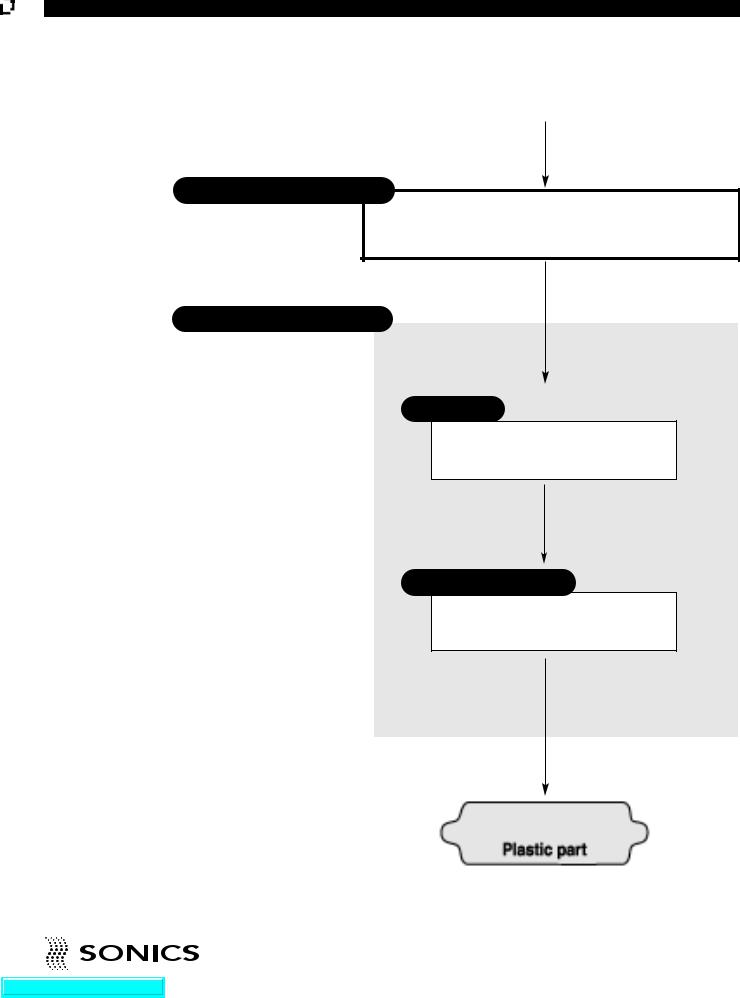
“SONICS” ULTRASONIC ASSEMBLY SYSTEMS
Power Supply/Generator
Hand Gun
50/60 Hz Electrical power
Generates ultrasonic electrical energy (20/30/40 kHz)
Ultrasonic electrical energy
Converter
Transforms ultrasonic electrical energy to ultrasonic mechanical vibrations
Ultrasonic Vibrations
Horn/Replaceable Tip
Contacts and transfers vibrational energy to plastic part
Ultrasonic Vibrations
• • • • • • • • • • • • • • • • • • • • • • • • • • • • • • • • • • • • • • • • • • • • • • • • • • • • • • • • • • • • • • • • • • • • • • • • • • • • • • • • • • • • • • • • • • • • • • • • • • • • • • • • • • • •
I NS TR UC T ION M AN U AL • H AN D H ELD WELD E RS |
9 |
Go To Top Of Document
GLOSSARY OF ULTRASO NIC TERMS
POWER SUPPLY/GENERATOR – The solid state power supply converts standard 50/60 Hz electrical power to 20,000, 30,000 or 40,000 Hz (20/30/40
kHz) electrical energy.
CONVERTER – The converter changes the high frequency electrical energy
supplied by the power supply to high frequency mechanical vibrations. TIP/HORN – The tip/horn is a tuned component of the system which comes
in contact with the parts to be assembled. The tip/horn 1) transfers the ultrasonic vibrations produced from the converter to the parts being welded,
and 2) applies necessary force to the assembly while the material resolidifies. AMPLITUDE – The peak to peak excursion of a horn at its output face.
• • • • • • • • • • • • • • • • • • • • • • • • • • • • • • • • • • • • • • • • • • • • • • • • • • • • • • • • • • • • • • • • • • • • • • • • • • • • • • • • • • • • • • • • • • • • • • • • • • • • • • • • • • • •
10 INS TRUCTI ON M ANU AL • H AN D H E LD WE LD E R S
Go To Top Of Document
INSTALLATIO N AND SE T UP
The line cord of the controller/power supply is equipped with a 3- prong, grounding plug. Do not, under any circumstances, remove the ground prong. The plug must be plugged into a mating 3-prong, grounding type outlet.
If power supply is to be run continuously, air cooling of the converter and horn is required. Use clean, dry compressed air filtered down to 5 microns.
Do not plug the power supply into an electrical outlet until all other connections have been made.
ELECTRICAL POWER REQUIREMENTS
The power supply requires a fused, single-phase, standard 3-terminal grounding type receptacle capable of supplying the requisite voltage and current. (Standard 120 volts or optional 220 volts, 50/60 Hz, regulated
between 95-135 volts or 190-265 volts, respectively.)
SETTING UP
The power supply is a free-standing assembly. It should be installed in a clear, uncluttered location that is free from excessive dirt, dust, corrosive fumes, and temperature and humidity extremes. The selected installation site should be near the electrical power source and away from equipment that generates abnormally high electrical transients. Observe the following additional instructions when installing the equipment:
a.Allow at least 6 inches (152.4mm) at the rear of the power supply for cable connections.
b.Position the power supply so that the front panel controls are visible and readily accessible.
c.The power supply is air cooled; allow sufficient space around the assembly to ensure adequate ventilation. If the power supply must be housed in a confined space, forced air cooling may be necessary to keep surrounding air within acceptable ambient temperature limits. Periodically check the ventilation grille and clean as necessary.
ELECTRICAL CONNECTIONS
When making the initial electrical connections, make sure the power is disconnected and follow these precautions.
1.Do not strain or kink the cables. When going around corners, allow as wide a bend as possible. Do not run the cables parallel to any power line within a distance of less than 1 foot (305mm).
2.To prevent the possibility of an electrical shock, ensure that the power supply line cord is properly grounded. Also make sure that the voltage rating of the electrical power source matches the power supply requirement.
3.Check with your electrician if you have any wiring questions.
• • • • • • • • • • • • • • • • • • • • • • • • • • • • • • • • • • • • • • • • • • • • • • • • • • • • • • • • • • • • • • • • • • • • • • • • • • • • • • • • • • • • • • • • • • • • • • • • • • • • • • • • • • • •
I NS T RU C T IO N MA NU A L • H A N D H E L D W ELD ERS |
11 |
Go To Top Of Document
Loading...