

Page 1

Model GXT
Power Supply
I N S T R U C T I O N M A N U A L
Sonics & Materials, Inc.
Page 2

W A R N I N G
SAFETY PRECAUTIONS
READ BEFORE INSTALLING OR USING THE EQUIPMENT
This system has been designed to assure maximum operator safety.
However, no design can completely protect against improper usage. For
maximum safety and equipment protection, observe the following warnings
at all times and read the instruction manual carefully before you attempt to
operate the equipment.
– High voltage is present in the equipment. Disconnect plug before
removing cover or servicing.
– Make sure equipment is properly grounded with a 3-prong plug. Before
plugging in equipment, test outlet for proper earth grounding.
– Ultrasonic welders operate above normal audibility for most people. Ear
protection is recommended.
Sonics & Materials, Inc.
Corporate Headquarters European Office
53 Church Hill Road • Newtown, CT 06470 USA 13, Rue Pre-de-la-Fontaine • CH - 1217 Meyrin/Satigny, Switzerland
203.270.4600 • 800.745.1105 • 203.270.4610 fax (41) (0) 22/364 1520 • (41) (0) 22/364 2161 fax
www.sonics.com • info@sonics.com [email protected]
Information contained in this manual is subject to change without notice. Sonics & Materials, Inc. is not responsible for any typographic errors.
© Sonics & Materials, Inc. 2010 Printed in
• • • • • • • • • • • • • • • • • • • • • • • • • • • • • • • • • • • • • • • • • • • • • • • • • • • • • • • • • • • • • • • • • • • • • • • • • • • • • • • • • • • • • • • • • • • • • • • • • • • • • • • • • • • •
Go To Top Of Document
I N ST R U C T ION M ANU A L • M OD E L GX T PO W E R S U P P LY
U.S Rev 01, 9/10
1
Page 3

T A B L E O F C O N T E N T S
IMPORTANT SERVICE LITERATURE . . . . . . . . . . . . . . . . . . . . . . . . . . . .4
Manual Change Information . . . . . . . . . . . . . . . . . . . . . . . . . . . . . .4
UNPACKING AND INSPECTION . . . . . . . . . . . . . . . . . . . . . . . . . . . . . . . .5
Visible Loss or Damage . . . . . . . . . . . . . . . . . . . . . . . . . . . . . . . . .5
Concealed Loss or Damage . . . . . . . . . . . . . . . . . . . . . . . . . . . . . .5
INTRODUCTION . . . . . . . . . . . . . . . . . . . . . . . . . . . . . . . . . . . . . . . . . . . . .6
OVERVIEW OF ULTRASONIC PLASTICS ASSEMBLY . . . . . . . . . . . . . . .6
What is Ultrasonics? . . . . . . . . . . . . . . . . . . . . . . . . . . . . . . . . . . . .6
Principal of Ultrasonic Assembly . . . . . . . . . . . . . . . . . . . . . . . . . .6
Ultrasonic Assembly Systems . . . . . . . . . . . . . . . . . . . . . . . . . . . .6
GLOSSARY OF ULTRASONIC TERMS . . . . . . . . . . . . . . . . . . . . . . . . . . .8
INSTALLATION . . . . . . . . . . . . . . . . . . . . . . . . . . . . . . . . . . . . . . . . . . . . . .9
Electrical Power Requirements . . . . . . . . . . . . . . . . . . . . . . . . . . . .9
Setting Up . . . . . . . . . . . . . . . . . . . . . . . . . . . . . . . . . . . . . . . . . . . .9
Electrical Connections . . . . . . . . . . . . . . . . . . . . . . . . . . . . . . . . .10
Cable Connections
Cable Connections
Available Converters . . . . . . . . . . . . . . . . . . . . . . . . . . . . . . . . . . .13
– For Models with 700 to 2200 Watts Power
– For Models with 3000 or 4000 Watts Power
. .11
.12
OPERATING PROCEDURES . . . . . . . . . . . . . . . . . . . . . . . . . . . . . . . . . .14
Front Panel Controls and Indicators . . . . . . . . . . . . . . . . . . . . . . .14
Keying in Parameters . . . . . . . . . . . . . . . . . . . . . . . . . . . . . . . . . .16
Operational Features . . . . . . . . . . . . . . . . . . . . . . . . . . . . . . . . . . .17
Starting up the Power Supply . . . . . . . . . . . . . . . . . . . . . . . . . . . .17
Initial Operation . . . . . . . . . . . . . . . . . . . . . . . . . . . . . . . . . . . . . . .18
Ready Screens . . . . . . . . . . . . . . . . . . . . . . . . . . . . . . . . . . . . . . .18
Time Settings . . . . . . . . . . . . . . . . . . . . . . . . . . . . . . . . . . . . . . . .20
Amplitude/Pressure . . . . . . . . . . . . . . . . . . . . . . . . . . . . . . . . . . . .21
Trigger . . . . . . . . . . . . . . . . . . . . . . . . . . . . . . . . . . . . . . . . . . . . . .21
ADDITIONAL FEATURES AND FUNCTIONS . . . . . . . . . . . . . . . . . . . . .22
Job Storage . . . . . . . . . . . . . . . . . . . . . . . . . . . . . . . . . . . . . . . . . .22
Frequency Display . . . . . . . . . . . . . . . . . . . . . . . . . . . . . . . . . . . . .23
Overload Protection . . . . . . . . . . . . . . . . . . . . . . . . . . . . . . . . . . .23
KEYPAD SECURITY . . . . . . . . . . . . . . . . . . . . . . . . . . . . . . . . . . . . . . . . .24
PRINT LINE OUTPUT . . . . . . . . . . . . . . . . . . . . . . . . . . . . . . . . . . . . . . . .25
AUTOMATION INTERFACE & I/O CONTROLS . . . . . . . . . . . . . . . . . . . .27
External Job Address Lines . . . . . . . . . . . . . . . . . . . . . . . . . . . . .29
Go To Top Of Document
• • • • • • • • • • • • • • • • • • • • • • • • • • • • • • • • • • • • • • • • • • • • • • • • • • • • • • • • • • • • • • • • • • • • • • • • • • • • • • • • • • • • • • • • • • • • • • • • • • • • • • • • • • • •
I N ST R U C T ION M ANU A L • M OD E L GX T PO W E R S U P P LY
2
Page 4

MAINTENANCE . . . . . . . . . . . . . . . . . . . . . . . . . . . . . . . . . . . . . . . . . . . . .30
General . . . . . . . . . . . . . . . . . . . . . . . . . . . . . . . . . . . . . . . . . . . . .30
Repairs / Service . . . . . . . . . . . . . . . . . . . . . . . . . . . . . . . . . . . . . .30
WARRANTY . . . . . . . . . . . . . . . . . . . . . . . . . . . . . . . . . . . . . . . . . . . . . . . .31
Limitation of Warranty . . . . . . . . . . . . . . . . . . . . . . . . . . . . . . . . . .31
APPENDIX . . . . . . . . . . . . . . . . . . . . . . . . . . . . . . . . . . . . . . . . . . . . . . . . .32
Print Line Output Data Items . . . . . . . . . . . . . . . . . . . . . . . . . . . .32
Automation Interface & I/O Controls . . . . . . . . . . . . . . . . . . . . . . .35
Source/Sink Inputs and Outputs . . . . . . . . . . . . . . . . . . . . . . . . . .35
Source/Sink Digital I/O Configuration . . . . . . . . . . . . . . . . . . . . . .36
Sinking Output to PLC Input Diagram . . . . . . . . . . . . . . . . . . . . .37
PLC Output to Sinking Input Diagram . . . . . . . . . . . . . . . . . . . . .37
PLC Output to Sourcing Input Diagram . . . . . . . . . . . . . . . . . . . .37
Two Isolated Loop Supplies . . . . . . . . . . . . . . . . . . . . . . . . . . . . .38
I/O Timing Diagram – Automated Controls . . . . . . . . . . . . . . . . . .38
PLC Sample Code . . . . . . . . . . . . . . . . . . . . . . . . . . . . . . . . . . . .39
Drawings . . . . . . . . . . . . . . . . . . . . . . . . . . . . . . . . . . . . . . . . . . . .41
G-Series Switches . . . . . . . . . . . . . . . . . . . . . . . . . . . . . . . . . . . . .49
Go To Top Of Document
• • • • • • • • • • • • • • • • • • • • • • • • • • • • • • • • • • • • • • • • • • • • • • • • • • • • • • • • • • • • • • • • • • • • • • • • • • • • • • • • • • • • • • • • • • • • • • • • • • • • • • • • • • • •
I N ST R U C T ION M ANU A L • M OD E L GX T PO W E R S U P P LY
3
Page 5

I M P O R T A N T S E R V I C E L I T E R A T U R E
The system supplied with this instruction manual is constructed of the finest
material and the workmanship meets the highest manufacturing standards.
It has been thoroughly tested and inspected before leaving the factory and
when used in accordance with the procedures outlined in this manual, will
provide you with many years of safe and dependable service.
NOTE: Please read
carefully before
operating the
equipment, then forward
to your service
department.
MANUAL CHANGE INFORMATION
We continually strive to be at the fore f ron t of the latest electro n i c
developments by adding circuit and component improvements to our
equipment as soon as they are developed and tested.
Sometimes, due to printing and shipping re q u i rements, we cannot
incorporate these changes immediately into printed manuals. Hence, your
manual may contain new change information. Change information, if any, is
located in the Appendix.
We reserve the right to make any changes in the design or construction of
our equipment at any time, without incurring any obligation to make any
change whatsoever in units previously delivered.
The technical data and schematics in the manual are for informational
purposes only and may not reflect the current configuration being shipped
from our factory. Upon formal request, complete and up-to-date information
can be provided from the factory free of charge.
Go To Top Of Document
• • • • • • • • • • • • • • • • • • • • • • • • • • • • • • • • • • • • • • • • • • • • • • • • • • • • • • • • • • • • • • • • • • • • • • • • • • • • • • • • • • • • • • • • • • • • • • • • • • • • • • • • • • • •
I N ST R U C T ION M ANU A L • M OD E L GX T PO W E R S U P P LY
4
Page 6

U N P A C K I N G A N D I N S P E C T I O N
Before unpacking the equipment, check the shipping carton for any visible
damage. If you see any, be sure to follow the procedures described below
under “Visible Loss or Damage.” Otherwise, proceed to remove the
equipment from the carton. Before storing any packing material, check it
carefully for small parts. Then perform a visual inspection of the equipment
to detect any evidence of damage which might have occurred during
NOTE: We recommend
keeping all carton(s) and
packing material in case
it might be necessary to
move the equipment, or
to ship it for repair.
shipment. Check the following:
1. all components against the enclosed packing list,
2. all module plug-in units,
3. all wire plug-in connections.
The equipment was carefully packed and thoroughly inspected before
leaving our factory. All units are tested and checked for problems prior to
shipping. It is asked that when a problem does occur that all parts and
components be inspected for damage (especially when the unit is not in
working order when received). Responsibility for safe delivery was assumed
by the carrier upon acceptance of the shipment. Claims for loss of damage
sustained in transit must therefore be made upon the carrier, as follows:
VISIBLE LOSS OR DAMAGE
Any external evidence of loss or damage must be noted on the freight bill or
express receipt, and signed by the carrier’s agent. Failure to adequately
describe such external evidence of loss or damage may result in the carrier’s
refusal to honor a damage claim. The form required to file such a claim will
be supplied by the carrier.
CONCEALED LOSS OR DAMAGE
Concealed loss or damage means loss or damage which does not become
apparent until the merchandise has been unpacked. The contents might
have been damaged in transit due to rough handling even though the
container may not show external damage. When the damage is discovered
upon unpacking, make a written request for inspection by the carrier’s agent
within 48 hours of the delivery date. Then file a claim with the carrier since
such damage is the carrier’s responsibility. The form required to file such a
claim will be supplied by the carrier. Do not destroy packing materials, or
move material from one location to another before the carrier makes their
inspection.
If the system or any unit is damaged, notify Sonics. Sonics will arrange for
repair or replacement of damaged equipment without waiting for the claim
against the carrier to be settled, provided a new purchase order is issued to
cover the repair or replacement costs. Should any damage, shortage or
discrepancy exist, please notify us immediately.
Go To Top Of Document
• • • • • • • • • • • • • • • • • • • • • • • • • • • • • • • • • • • • • • • • • • • • • • • • • • • • • • • • • • • • • • • • • • • • • • • • • • • • • • • • • • • • • • • • • • • • • • • • • • • • • • • • • • • •
I N ST R U C T ION M ANU A L • M OD E L GX T PO W E R S U P P LY
5
Page 7

I N T R O D U C T I O N
The GXT power supply is an ultrasonic generator with automatic frequency
tuning and a built-in Microprocessor that features time controls. The
Microprocessor is programmed with a multi-function keypad and information
is displayed on the back-lit liquid crystal display (LCD). This power supply
can be used with a pneumatic press or actuator, or with a stand-alone
converter.
O V E R V I E W O F U L T R A S O N I C P L A S T I C S
A S S E M B L Y
WHAT IS ULTRASONICS?
Ultrasonics refers to vibrational waves with a frequency above the human
audible range which is usually above 18,000 cycles per second (Hz).
PRINCIPLE OF ULTRASONIC ASSEMBLY
The basic principle of ultrasonic assembly involves conversion of high
frequency electrical energy to high frequency mechanical energy in the form
of reciprocating vertical motion which, when applied to a thermoplastic,
generates frictional heat at the plastic/plastic or plastic/metal interface. In
ultrasonic welding, this frictional heat melts the plastic, allowing the two
surfaces to fuse together; in ultrasonic staking or insertion, the controlled
flow of molten plastic is used to capture or lock another material in place
(staking) or encapsulate a metal insert (insertion).
ULTRASONIC ASSEMBLY SYSTEMS
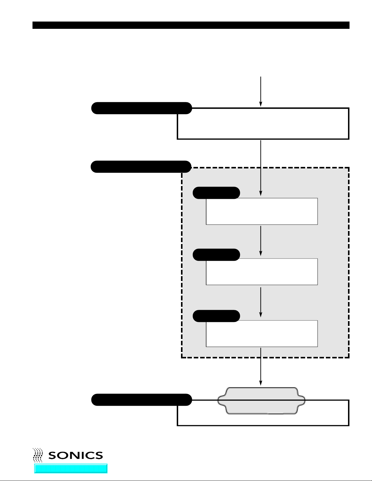
Sonics ultrasonic assembly systems are generally composed of the following
major elements: a power supply, converter, booster, horn, pneumatic press
and holding fixture, as detailed in the diagram on the next page. A review of
this diagram will help you understand the basic elements involved in the
assembly process and their relation to each other.
Go To Top Of Document
• • • • • • • • • • • • • • • • • • • • • • • • • • • • • • • • • • • • • • • • • • • • • • • • • • • • • • • • • • • • • • • • • • • • • • • • • • • • • • • • • • • • • • • • • • • • • • • • • • • • • • • • • • • •
I N ST R U C T ION M ANU A L • M OD E L GX T PO W E R S U P P LY
6
Page 8
SONICS ULTRASONIC ASSEMBLY SYSTEMS
Power Supply/Generator
Actuator/Press
Provides compressive force
and mounting for Converter,
Booster, Horn assembly
50/60 Hz
Electrical power
Generates ultrasonic electrical energy
(15/20/40 kHz)
Ultrasonic
electrical energy
Converter
Transforms ultrasonic electrical energy
to ultrasonic mechanical vibrations
Ultrasonic Vibrations
Holding Fixture
Aligns and supports part
Booster
Increases or decreases amplitude
Ultrasonic Vibrations
Horn
Contacts and transfers vibrational
energy to plastic part
Ultrasonic Vibrations
Plastic part
Go To Top Of Document
• • • • • • • • • • • • • • • • • • • • • • • • • • • • • • • • • • • • • • • • • • • • • • • • • • • • • • • • • • • • • • • • • • • • • • • • • • • • • • • • • • • • • • • • • • • • • • • • • • • • • • • • • • • •
I N ST R U C T ION M ANU A L • M OD E L GX T PO W E R S U P P LY
7
Page 9

G L O S S A R Y O F U L T R A S O N I C T E R M S
POWER SUPPLY/GENERATOR – The solid state power supply converts
standard 50/60 Hz electrical energy to 15,000 Hz, 20,000 Hz or 40,000 Hz
(15/20/40 kHz) electrical energy.
ACTUATOR/WELDING PRESS – The pneumatic actuator provides compressive force and mounting for the converter, booster and horn assembly.
The tabletop press consists of a base assembly, column and actuator (head).
CONVERTER – The converter changes the high frequency electrical energy
supplied by the power supply to high frequency mechanical vibrations.
BOOSTER – Successful ultrasonic welding often depends on having the
right amplitude at the horn face. Often it is not possible to design a horn
which has both the necessary shape and required gain (ratios of input
amplitude to output amplitude). In such cases, a booster is placed between
the converter and the horn to either increase or decrease the amplitude of
the horn. In addition to changing/maintaining the amplitude, the booster
provides support and alignment in the welding system.
HORN – The horn is a tuned component of the system which comes in
contact with the parts to be assembled. The horn 1) transfers the ultrasonic
vibrations produced from the converter to the parts being welded, and 2)
applies necessary force to the assembly while the material resolidifies.
HOLDING FIXTURE – The holding fixture or nest assures proper alignment
and support of the parts being assembled.
Go To Top Of Document
• • • • • • • • • • • • • • • • • • • • • • • • • • • • • • • • • • • • • • • • • • • • • • • • • • • • • • • • • • • • • • • • • • • • • • • • • • • • • • • • • • • • • • • • • • • • • • • • • • • • • • • • • • • •
I N ST R U C T ION M ANU A L • M OD E L GX T PO W E R S U P P LY
8
Page 10
I N S T A L L A T I O N
ELECTRICAL POWER REQUIREMENTS
The power supply requires a fused, single-phase, standard 3-terminal
grounding type receptacle capable of supplying the requisite voltage and
current. Refer to the table below for power specification.
The line cord of the
controller/power supply
is equipped with a 3prong, grounding plug.
Do not, under any
circumstances, remove
the ground prong. The
plug must be plugged
into a mating 3-prong,
grounding type outlet.
NOTE: If power supply
is to be run
continuously, air cooling
of the converter and
horn is required. Use
clean, dry compressed
air filtered down to 5
microns (supplied to
converter fitting – see
page 12).
POWER SPECIFICATIONS
Power Rating/
Fuse rating
Model Frequency 115 vac 230 vac
GXT400-40 400w - 40 kHz 15 amps 10 amps
GXT800-40 800w - 40 kHz 15 amps 10 amps
GXT1200-20 1200w - 20 kHz 15 amps 10 amps
GXT1700-20 1700w - 20 kHz N/A 20 amps
GXT2200-20 2200w - 20 kHz N/A 20 ampT
GXT3500-20 3500w - 20 kHz N/A 30 ampT
GXT2200-15 2200w - 15 kHz N/A 20 amps
GXT3500-15 3500w - 15 kHz N/A 30 amps
GXT4500-15 4500w - 15 kHz N/A 30 amps
SETTING UP
The power supply is a free-standing assembly. It should be installed in a
clear, uncluttered location that is free from excessive dirt, dust, corrosive
fumes, and temperature and humidity extremes. The selected installation site
should be near the electrical power source and away from equipment that
generates abnormally high electrical transients. Observe the following
additional instructions when installing the equipment:
a. Allow at least 6 inches (152.4mm) at the rear of the power supply for cable
connections.
b. Position the power supply so that the front panel controls are visible and
readily accessible.
c. The power supply is air cooled; allow sufficient space around the
assembly to ensure adequate ventilation. If the power supply must be
housed in a confined space, forced air cooling may be necessary to keep
surrounding air within acceptable ambient temperature limits. Periodically
check the ventilation grille and clean as necessary.
¥ ¥ ¥ ¥ ¥ ¥ ¥ ¥ ¥ ¥ ¥ ¥ ¥ ¥ ¥ ¥ ¥ ¥ ¥ ¥ ¥ ¥ ¥ ¥ ¥ ¥ ¥ ¥ ¥ ¥ ¥ ¥ ¥ ¥ ¥ ¥ ¥ ¥ ¥ ¥ ¥ ¥ ¥ ¥ ¥ ¥ ¥ ¥ ¥ ¥ ¥ ¥ ¥ ¥ ¥ ¥ ¥ ¥ ¥ ¥ ¥ ¥ ¥ ¥ ¥ ¥ ¥ ¥ ¥ ¥ ¥ ¥ ¥ ¥ ¥ ¥ ¥ ¥ ¥ ¥ ¥ ¥ ¥ ¥ ¥ ¥ ¥ ¥ ¥ ¥ ¥
¥ ¥ ¥ ¥ ¥ ¥ ¥ ¥ ¥ ¥ ¥
I N ST R U C T IO N M AN U A L • M O D E L G X T P O WE R S UP P LY
9
Page 11

NOTE: Do not plug the
power supply into an
electrical outlet until all
other connections have
been made.
ELECTRICAL CONNECTIONS
The standard cable supplied with a Sonics press is 10 feet. Optional
extension cables are available up to 15 feet without modification.
When making the initial electrical connections, make sure the power is
disconnected and follow these precautions.
1. Do not strain or kink the cables. When going around corners, allow as
wide a bend as possible. Do not run the cables parallel to any power line
within a distance of less than 1 foot (305 mm).
2. To prevent the possibility of an electrical shock, ensure that the power
supply line cord is properly grounded. Also make sure that the voltage
rating of the electrical power source matches the power supply
requirement (refer to the “Power Specifications” table on preceding page).
3. Check with your electrician if you have any wiring questions.
Go To Top Of Document
• • • • • • • • • • • • • • • • • • • • • • • • • • • • • • • • • • • • • • • • • • • • • • • • • • • • • • • • • • • • • • • • • • • • • • • • • • • • • • • • • • • • • • • • • • • • • • • • • • • • • • • • • • • •
I N ST R U C T ION M ANU A L • M OD E L GX T PO W E R S U P P LY
10
Page 12
NOTE: Detailed wiring
diagrams are supplied in
the Appendix at the
back of this manual.
CABLE CONNECTIONS – For Models with 700 to 2200
Watts Power:
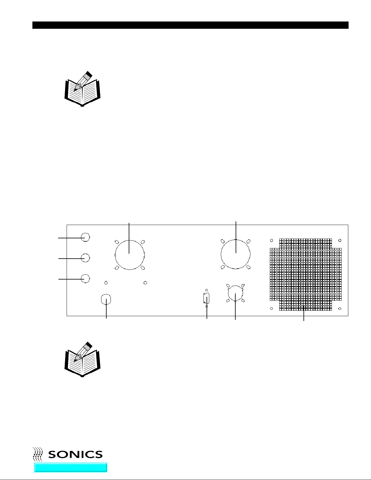
Located at the rear of the power supply are the cable connections as
illustrated below. (The interconnecting cables will be supplied with your
system.)
J1, a round, 12-pin RF cable that connects the welding press or
❶
converter to the power supply.
J2, an actuation cable that connects the power supply to a trigger source
❷
(press cable or external trigger source.) Refer to wiring diagrams in
Appendix.
❸
The power line cord that plugs into the appropriate electrical outlet.
Once these connections have been made, the power supply is ready for
operation. If applicable, be sure to consult your welding press instruction
manual to insure that all connections on the press side are correct, and
❺
➏
❼
NOTE: To see a list of
converters that can be
connected to the power
supply, see the table on
the following page.
❸
❹
❶
❽ ❷
that the press is ready for operation.
Also located at the rear of the power supply are the following:
❹ J5 External I/O
❺
Fuse (0.5 amp - internal low voltage)
Line fuse (based on requirements listed in “Power Specifications” table,
➏
page 9),
Line fuse (based on requirements listed in “Power Specifications” table,
❼
page 9),
Fan
Go To Top Of Document
❽
J4 Serial Output
• • • • • • • • • • • • • • • • • • • • • • • • • • • • • • • • • • • • • • • • • • • • • • • • • • • • • • • • • • • • • • • • • • • • • • • • • • • • • • • • • • • • • • • • • • • • • • • • • • • • • • • • • • • •
I N ST R U C T ION M ANU A L • M OD E L GX T PO W E R S U P P LY
11
Page 13
NOTE: Detailed wiring
diagrams are supplied in
the Appendix at the
back of this manual.
CABLE CONNECTIONS – For Models with 3000 or 4000
Watts Power:
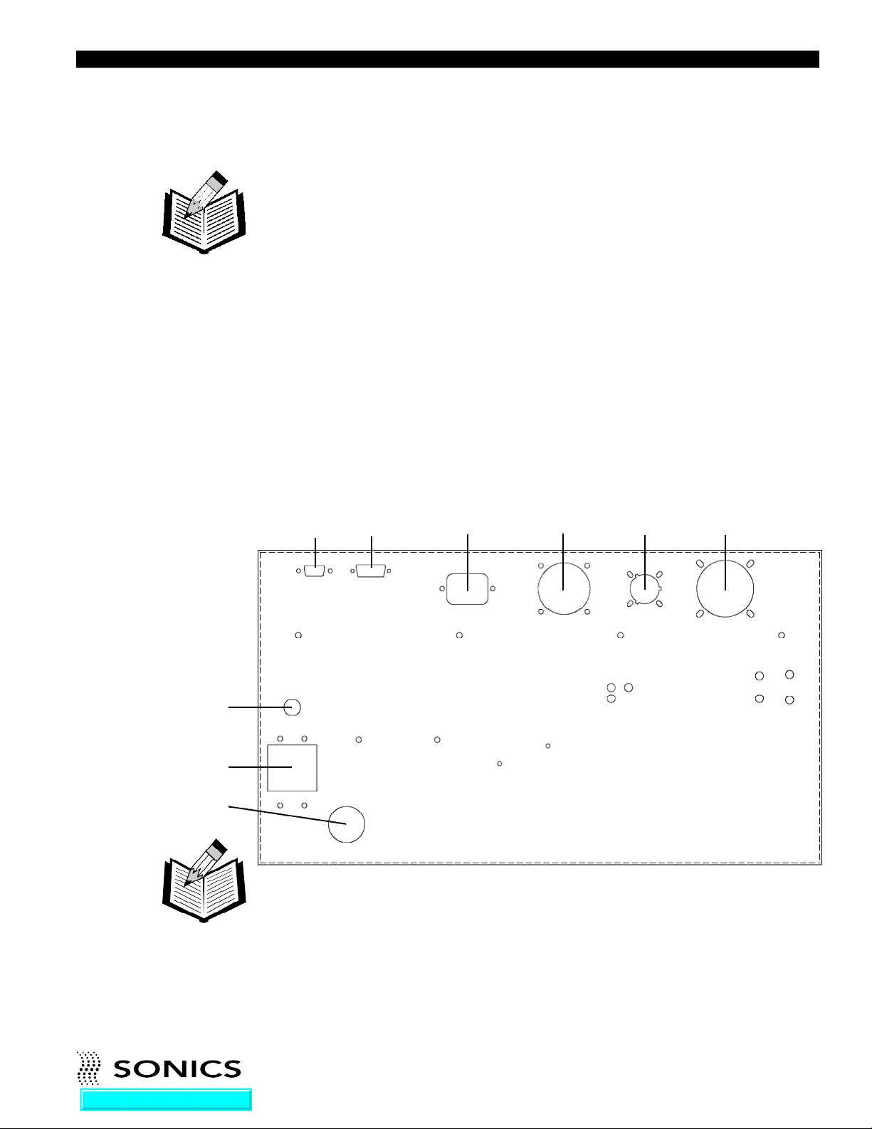
Located at the rear of the power supply are the cable connections as
illustrated below. (The interconnecting cables will be supplied with your
system.)
J1, a round, 12-pin RF cable that connects the welding press or
❶
converter to the power supply.
J2, an actuation cable that connects the power supply to a trigger source
❷
(press cable or external trigger source.) Refer to wiring diagrams in
Appendix.
❸
The power line cord that plugs into the appropriate electrical outlet.
Once these connections have been made, the power supply is ready for
operation. If applicable, be sure to consult your welding press instruction
manual to insure that all connections on the press side are correct, and
that the press is ready for operation.
❺
➏
❸
❽ ❷ ❶
Also located at the rear of the power supply are the following:
❹❼ ❾
NOTE: To see a list of
converters that can be
connected to the power
supply, see the table on
the following page.
Go To Top Of Document
❹
J5 External I/O
❺
Fuse (0.5 amp - internal low
voltage)
Circuit breaker
➏
• • • • • • • • • • • • • • • • • • • • • • • • • • • • • • • • • • • • • • • • • • • • • • • • • • • • • • • • • • • • • • • • • • • • • • • • • • • • • • • • • • • • • • • • • • • • • • • • • • • • • • • • • • • •
I N ST R U C T ION M ANU A L • M OD E L GX T PO W E R S U P P LY
❼
J4 Serial Output
❽
J3 Linear Encoder
J6 on 15 kHz models only.
❾
Press motor connector.
12
Page 14
AVAILABLE CONVERTERS FOR POWER SUPPLIES
Item No. Description
CV00016 15 kHz with Button connector (O-ring mount)
CV00161 15 kHz with Lemo connector (O-ring mount)
CV00034 15 kHz with Button connector (O-ring mount) rated up to
4500 watts
CV00341 15 kHz with Lemo connector (O-ring mount) rated up to
4500 watts
CV00015 20 kHz with Button connector (O-ring mount)
CVR0015 20 kHz with Button connector (rigid mount)
CV00151 20 kHz with Lemo connector (O-ring mount)
CVR0151 20 kHz with Lemo connector (rigid mount)
CV00154 20 kHz with Lemo connector and fitting for
air cooling (O-ring mount)
CVR0154 20 kHz with Lemo connector and fitting for
air cooling (rigid mount)
CV00157 20 kHz with Button connector and fitting for
air cooling (O-ring mount)
CVR0157 20 kHz with Button connector and fitting for
air cooling (rigid mount)
CV00158 20 kHz Hand Gun with handles and cables (O-ring mount)
CVR0158 20 kHz Hand Gun with handles and cables (rigid mount)
CV00331 20 kHz with Fischer connector
CV00334 20 kHz with Fischer connector and fitting
for air cooling
CVR0023 40 kHz with Button connector (rigid mount)
CVR0231 40 kHz with Lemo connector (rigid mount)
CVR0233 40 kHz with SHV connector side mounted (rigid mount)
CVR0234 40 kHz with Lemo connector and fitting for
air cooling (rigid mount)
¥ ¥ ¥ ¥ ¥ ¥ ¥ ¥ ¥ ¥ ¥ ¥ ¥ ¥ ¥ ¥ ¥ ¥ ¥ ¥ ¥ ¥ ¥ ¥ ¥ ¥ ¥ ¥ ¥ ¥ ¥ ¥ ¥ ¥ ¥ ¥ ¥ ¥ ¥ ¥ ¥ ¥ ¥ ¥ ¥ ¥ ¥ ¥ ¥ ¥ ¥ ¥ ¥ ¥ ¥ ¥ ¥ ¥ ¥ ¥ ¥ ¥ ¥ ¥ ¥ ¥ ¥ ¥ ¥ ¥ ¥ ¥ ¥ ¥ ¥ ¥ ¥ ¥ ¥ ¥ ¥ ¥ ¥ ¥ ¥ ¥ ¥ ¥ ¥ ¥ ¥
¥ ¥ ¥ ¥ ¥ ¥ ¥ ¥ ¥ ¥ ¥
I N ST R U C T IO N M AN U A L • M O D E L G X T P O WE R S UP P LY
13
Page 15
O P E R A T I N G P R O C E D U R E S
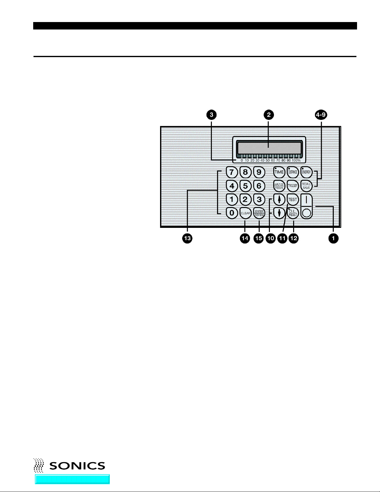
FRONT PANEL CONTROLS AND INDICATORS
Located on the front panel of the power supply are the following controls and
indicators:
1. ON/OFF keys which turn the unit on and off.
2. LCD SCREEN which displays various settings, parameters and prompts
as detailed in the following pages. In addition, during the weld process it
displays a load meter indicator showing the power level of ultrasonics that
is being delivered to the welding press (see #3 below).
3. LOAD METER SCALE from 0 to 100% which (in conjunction with
vertical line indicators on LCD display) shows the running power (bar
graph at bottom of display) and peak power (single vertical line at top of
display) during the weld. Peak power is reported as %Pmax after the cycle
(see page 16).
4. TIME key allows selection and display of time settings and permits
adjustment of time duration in .01 second increments (from 00.00 to 99.99
seconds) for five time parameters as follows:
a. Weld time
b. Hold Time
c. Delay time
d. Afterburst Time
e. Time Limit Low
Go To Top Of Document
f. Time Limit High
For a complete explanation of these parameters, refer to page 19.
• • • • • • • • • • • • • • • • • • • • • • • • • • • • • • • • • • • • • • • • • • • • • • • • • • • • • • • • • • • • • • • • • • • • • • • • • • • • • • • • • • • • • • • • • • • • • • • • • • • • • • • • • • • •
I N ST R U C T ION M ANU A L • M OD E L GX T PO W E R S U P P LY
14
Page 16

5. DISTANCE key. Option not available with Model GXT.
6. ENERGY key. Option not available with Model GXT.
7. A M P L I T U D E / P R E S S U R E key which controls adjustment of the
following amplitude and pressure settings of the system’s high-frequency
vibrations over the full operating range. (Major adjustments of amplitude
can be made through the use of different boosters – consult your press
manual for further information.)
a. Amplitude Setting
b. Amplitude Ramp (only on systems configured for more than 2200
watts)
c. Trigger Force (Press)
8. TRIGGER key which displays and permits selection of the trigger mode
from the following options –
a. Delay Timer
b Force/Pressure
c. Pretrigger - Top
9. RECALL/SAVE key which allows up to 15 different jobs to be stored
(saved) and recalled or changed upon demand.
10. ARROW keys (Up/Down) which allow scrolling through some menus and
also serve as a toggle for displayed parameter options in some menus.
11. TEST key which can be used to test ultrasonic operation and displays
idle losses of converter/booster/horn as a percentage of maximum power
when key is depressed. Also functions as a frequency display.
12. O.L. RESET key which resets the power supply following an overload
condition. Red LED in upper left corner indicates an overload condition
exists.
13. 0-9 NUMERIC KEY PAD which allows input of numeric data or
numeric selection options by pressing the keys.
14. CLEAR key which cancels a prior parameter value when a new value is
to be entered.
15. ENTER/REVIEW key which Enters data into the system as keyed in with
the numerical keys and displayed on the LCD screen. In Review function,
displays the alarm, mode and cycle information.
Go To Top Of Document
• • • • • • • • • • • • • • • • • • • • • • • • • • • • • • • • • • • • • • • • • • • • • • • • • • • • • • • • • • • • • • • • • • • • • • • • • • • • • • • • • • • • • • • • • • • • • • • • • • • • • • • • • • • •
I N ST R U C T ION M ANU A L • M OD E L GX T PO W E R S U P P LY
15
Page 17

KEYING IN PARAMETERS
To make numeric entries into a cursor location that is displayed on a screen
menu, use the numeric keypad. When the desired entry is displayed on the
LCD screen, use the ENTER key to register the new value. Entries are made
left to right.
The CLEAR key will clear an existing value to 0, displayed as a series of
dashes, and relocate the cursor to the extreme left-hand entry position ready
to accept entries again. As soon as a desired value is keyed in and displayed,
pressing the ENTER key makes the system accept that entry. If a number
value is not “Entered,” then it will not be accepted by the system and the
parameter value will return to its former setting (before any numerical values
were changed).
Go To Top Of Document
• • • • • • • • • • • • • • • • • • • • • • • • • • • • • • • • • • • • • • • • • • • • • • • • • • • • • • • • • • • • • • • • • • • • • • • • • • • • • • • • • • • • • • • • • • • • • • • • • • • • • • • • • • • •
I N ST R U C T ION M ANU A L • M OD E L GX T PO W E R S U P P LY
16
Page 18
OPERATIONAL FEATURES
– Adjustable Afterburst Timer to separate parts from horn.
– Adjustable tolerance limits in time (sec) with visual alarms.
– Information displays including: number of assemblies, number of rejects,
and number of cycles.
– Fault displays.
– Keypad security.
– Self-diagnostic input test.
– Storage capabilities of up to 15 jobs.
– RS-232 Printer monitor interface permits connection to a printer or
computer.
– External job selection when the keyboard is “locked.”
STARTING UP THE POWER SUPPLY
Press the ON/OFF key to turn the power supply on. The LCD screen will
briefly display “Start Sequence” and show wattage and fre q u e n c y
information. Then the LCD screen will show the following “ready” display:
00.00 sec 00 %Pmax
This display shows the last weld information for weld time and power. (After
power down and subsequent power up, values are cleared to zero.)
Go To Top Of Document
• • • • • • • • • • • • • • • • • • • • • • • • • • • • • • • • • • • • • • • • • • • • • • • • • • • • • • • • • • • • • • • • • • • • • • • • • • • • • • • • • • • • • • • • • • • • • • • • • • • • • • • • • • • •
I N ST R U C T ION M ANU A L • M OD E L GX T PO W E R S U P P LY
17
Page 19
INITIAL OPERATION
After the power supply is turned on (as described on previous page), follow
these steps:
1. Make sure that all necessary preparations have been made with regard to
the ultrasonic system and tooling, and that the items to be welded are in
position.
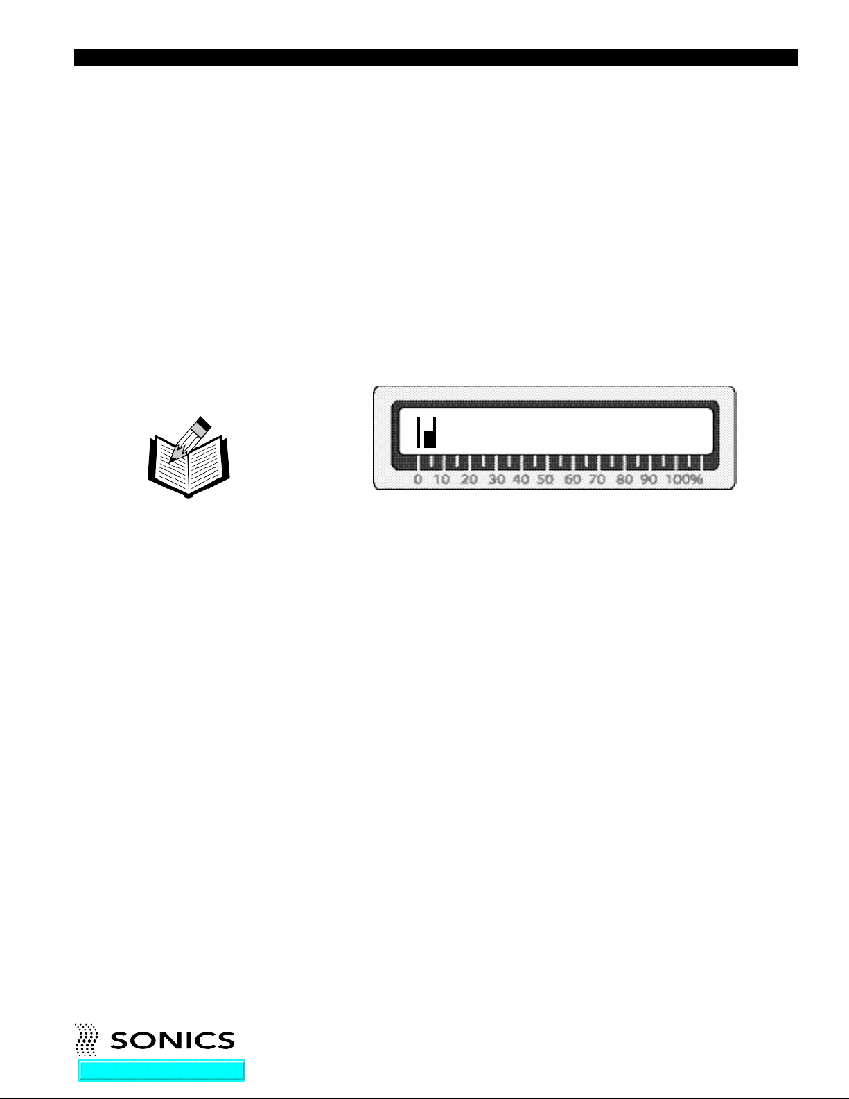
2. Press and hold the TEST button. While depressing the TEST button,
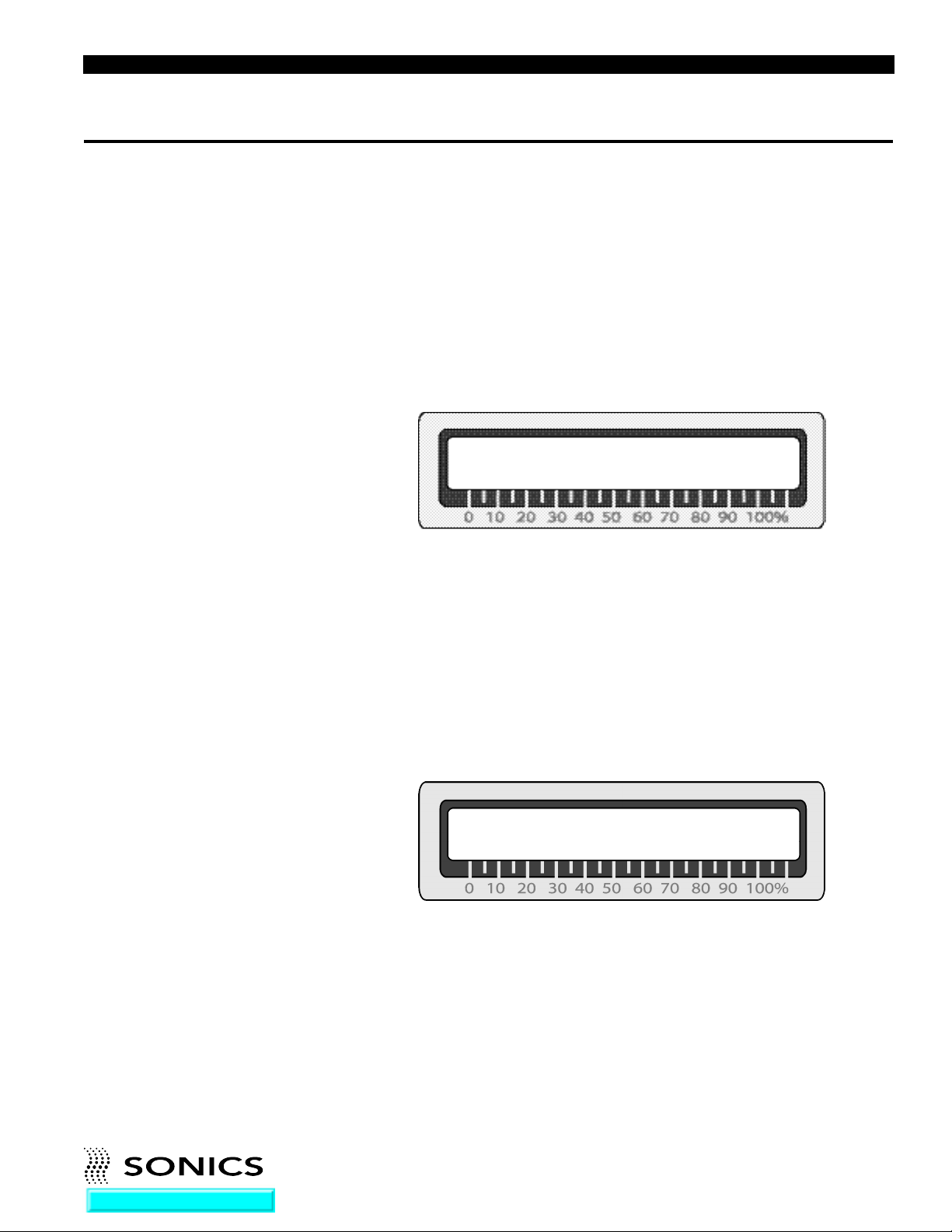
check the LCD display. Make sure the bar graph indicator on the LCD
display (a series of vertical lines that register to the 0 to 100% load meter
scale – see example below) does not exceed 20%.
0045 Watts
NOTE: The TEST and
Load Meter check
should always be done
for all cold start-ups,
and for any start-up after
the system has been idle
for 20 minutes or more.
During the testing process, keep in mind that the ultrasonics are only
activated as long as the TEST button is depressed – once you release the
TEST button, ultrasonics is terminated.
A bar graph indicator reading of above 20%, signals that there may be a
problem with the stack. Check your assembly and re-test.
3. The power supply is now ready for operation.
Frequency Display
The TEST key can also be used to display the running ultrasonic frequency
being used by the system. Refer to page 22 for more information.
READY SCREENS
In addition to the start-up ready screen (shown on page 16), there are 2 other
“ready” screens. The system must be displaying one of the 3 ready screens
in order for welding to commence. Welding cannot be initiated from any
other display. The other 2 ready screens are as follows:
Go To Top Of Document
• • • • • • • • • • • • • • • • • • • • • • • • • • • • • • • • • • • • • • • • • • • • • • • • • • • • • • • • • • • • • • • • • • • • • • • • • • • • • • • • • • • • • • • • • • • • • • • • • • • • • • • • • • • •
I N ST R U C T ION M ANU A L • M OD E L GX T PO W E R S U P P LY
18
Page 20
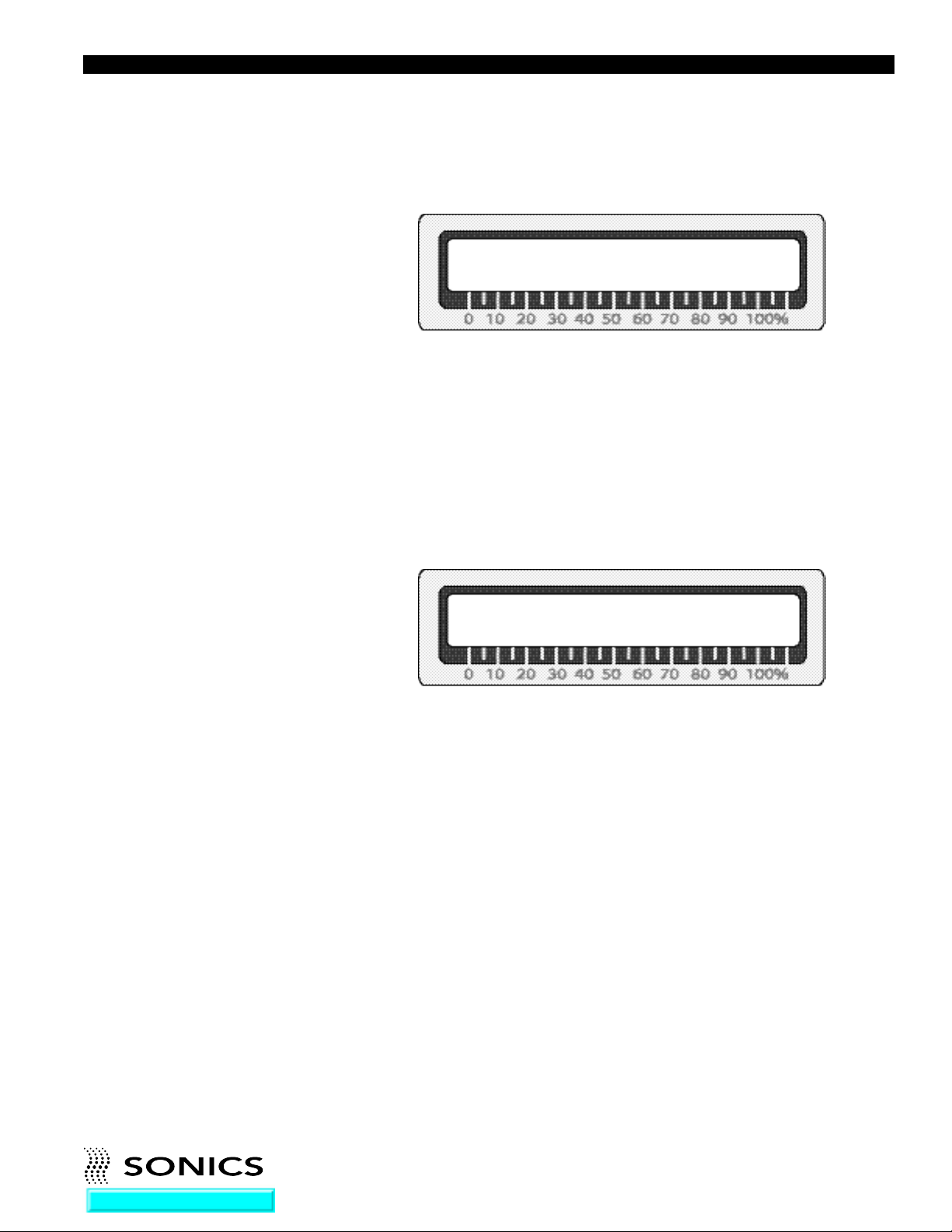
Alarm Screen
*Alarms* Time: – –
The Alarm screen displays information about the alarm(s) that have been
triggered by the system encountering parameters outside of the specified
tolerance limits. The screen will indicate an alarm that occurs in Time. If there
are no alarms, dashes will display. If there are alarms, an L (for Low limit,
indicating that the low limit was violated) and/or an H (for High limit,
indicating that the high limit was violated) will display. When a new cycle
begins, the system will automatically clear the current alarm.
Counter Screen
J02 Cycles: 00,004,678
CRC: 000,062 RAC: 0,000
The Counter screen displays information about the job number, the number
of cycles run to date, the customer resettable counter (CRC) and the
resettable alarm counter (RAC). The 2 resettable counters can be reset
whenever desired by pressing the Clear key when the counter screen is
displayed (the keypad must be unlocked).
Go To Top Of Document
• • • • • • • • • • • • • • • • • • • • • • • • • • • • • • • • • • • • • • • • • • • • • • • • • • • • • • • • • • • • • • • • • • • • • • • • • • • • • • • • • • • • • • • • • • • • • • • • • • • • • • • • • • • •
I N ST R U C T ION M ANU A L • M OD E L GX T PO W E R S U P P LY
19
Page 21

TIME SETTINGS
There are five time parameters, or timers, that can be set. They are accessed
by pressing the Time key which allows specification of the following time
parameters. The first menu display will show the following:
NOTE: If no time is
set, an error message
(“Set Weld Timer”) will
display prompting a
parameter entry.
NOTE: A review of the
Basic Weld Cycle Time
Line on page 47 gives
additional information
on how the weld cycle
and settings operate.
Weld Time – sets the duration of time for which ultrasonic vibrations are
applied to the parts. A time value must be entered in order to weld.
Press the Time key again (and successively after each menu display) to
advance to these next screen displays:
Hold Time – sets the duration of time for which pressure is maintained to
ensure proper bonding of the parts, after the actual weld time and with
ultrasonics off. (This allows the weld to cool.)
Delay Time – sets the duration of time allotted for pressure to build up after
the parts have been contacted and before the application of ultrasonic
vibrations to the horn. (“Delay Timer” must be selected as the trigger mode
– see page 20 – and a value equal to or greater than 0 must be set.)
Afterburst Time – sets the duration of time for another application of
ultrasonic vibrations to the horn (for “shake-off”) to ensure that the parts
being assembled do not adhere to the horn.
Time Limit Low – sets the low time alarm examination point (as a tolerance
limit). A time alarm will be triggered if the actual weld time is less than this
value. The time low alarm will show on the Alarm Screen display and will be
indicated by a flashing LED on the Time key. By specifying values for this
limit and the Time Limit High, a weld time “window” is created that defines a
”good weld.” (If no alarms are triggered – the weld cycle occurred within the
designated time limits.)
Go To Top Of Document
Time Limit High – sets the high time alarm examination point. A time alarm
will be triggered if the actual weld time is greater than this value. The time
high alarm will show on the Alarm Screen display and will be indicated by a
flashing LED on the Time key.
• • • • • • • • • • • • • • • • • • • • • • • • • • • • • • • • • • • • • • • • • • • • • • • • • • • • • • • • • • • • • • • • • • • • • • • • • • • • • • • • • • • • • • • • • • • • • • • • • • • • • • • • • • • •
I N ST R U C T ION M ANU A L • M OD E L GX T PO W E R S U P P LY
20
Page 22

AMPLITUDE/PRESSURE
Fine adjustments of the following amplitude and pressure settings can be
made by using the Amplitude/Pressure key. All settings range from 20%
(minimum) to 100% (maximum).
Amplitude Ramp – (only on systems configured for more than 2200 watts)
Used primarily for 15 kHz systems to ensure a slow start-up when welding
with big horns.
NOTE: Major
adjustments of
amplitude and pressure
are made on the press
through the use of
boosters and pressure
controls.
Trigger Force (Press) – this setting can be used to specify the pressure that
needs to be reached to trigger the ultrasonics when “Force/Pressure” has
been selected as the Trigger mode.
Amplitude Setting – this setting is used to specify the vibrational amplitude.
TRIGGER
Selection of the trigger mode is achieved by pressing the Trigger Key and
then using the Up/Down arrow keys as a toggle to select one of the following
modes to act as the trigger to start ultrasonics.
Delay Timer – selecting this mode means that the ultrasonics will be
triggered when the Delay Time specified in the Time menu is reached.
Force/Pressure – selecting this mode means that the ultrasonics will be
triggered when the Trigger Force (Pressure) specified in the Amplitude/
Pressure menu is achieved.
Pretrigger - Top – selecting this mode means that the ultrasonics will be
triggered as soon as the head assembly leaves its home (head up) position
and starts descent. This means that ultrasonics will be on before contact is
made with the parts to be welded.
Go To Top Of Document
• • • • • • • • • • • • • • • • • • • • • • • • • • • • • • • • • • • • • • • • • • • • • • • • • • • • • • • • • • • • • • • • • • • • • • • • • • • • • • • • • • • • • • • • • • • • • • • • • • • • • • • • • • • •
I N ST R U C T ION M ANU A L • M OD E L GX T PO W E R S U P P LY
21
Page 23
A D D I T I O N A L F E A T U R E S A N D F U N C T I O N S
JOB STORAGE
Up to 15 different jobs may be stored and recalled or changed upon demand.
Typical job parameters stored include Time and Power, Force Trigger, Limits,
and Amplitude.
Save
To use the job storage feature, press the Recall/Save key. If the “recall”
option is displayed on the screen press the button again. The Save display
appears as follow:
Save to Job #
— —
Saved jobs will be numbered 01 through 15. To save a job, use the numerical
keys to enter in the desired job number (01 – 15). Once the job number is
keyed in, press the ENTER key. All the parameters for that job will be saved
under the job number keyed in. The system will return to the ready screen.
Recall
To recall a job that has been saved, press the Recall/Save key. If the “save”
option is displayed on the screen press the button again. The Recall display
appears as follow:
Recall from Job #
— —
Recalled jobs are numbered 01 through 15. To recall a job, use the numerical
keys to enter in the desired job number (01 – 15). Once the job number is
keyed in, the settings for that job will be displayed on the various parameter
menus.
The System will not respond if there is no job saved under a number
corresponding to the numerical key pressed.
Go To Top Of Document
• • • • • • • • • • • • • • • • • • • • • • • • • • • • • • • • • • • • • • • • • • • • • • • • • • • • • • • • • • • • • • • • • • • • • • • • • • • • • • • • • • • • • • • • • • • • • • • • • • • • • • • • • • • •
I N ST R U C T ION M ANU A L • M OD E L GX T PO W E R S U P P LY
22
Page 24

FREQUENCY DISPLAY
The TEST key can also be used to display the running frequency. When the
press head is in the UP position, press and hold the TEST key for 3 seconds.
The information on the display will change from the power display (watts) to
a frequency counter display (Hz). After this switch, the power is captured (no
longer updated) and the frequency display will update every second. This
i n f o r mation can help diagnose problems with the horn and/or stack
assembly.
OVERLOAD PROTECTION
The overload protection circuit will terminate ultrasonics when the system is
operated under adverse conditions, i.e., improper tuning, excessive power
supply loading, loose or failed horn or booster, thereby protecting the power
supply and other system components. When an overload condition exists, a
repetitive beep will sound and the O. L. RESET button will illuminate and
remain lit until the button is pressed (regardless of whether the condition is
corrected or not). If a repeated overload condition exists, resolve the problem
before a failure of the power supply occurs.
If an overload condition exists, refer to the actuator instruction manual which
may recommend one of the following possible solutions:
— decrease horn force
— decrease amplitude (change booster or decrease output control)
— decrease downspeed
— check for loose or broken studs
— check the coupling surfaces between horn/booster and booster/converter
— check for cracked horn or booster
— check to see if the load meter exceeds 100% during weld process (if so,
a higher powered unit is needed)
If you cannot remedy the situation, contact Sonics’ Service Department at
1-800-745-1105.
Go To Top Of Document
• • • • • • • • • • • • • • • • • • • • • • • • • • • • • • • • • • • • • • • • • • • • • • • • • • • • • • • • • • • • • • • • • • • • • • • • • • • • • • • • • • • • • • • • • • • • • • • • • • • • • • • • • • • •
I N ST R U C T ION M ANU A L • M OD E L GX T PO W E R S U P P LY
23
Page 25
K E Y P A D S E C U R I T Y
The keypad can be “locked,” so that no new parameters or commands can
be entered via the keyboard, thereby preventing unauthorized cancellation or
adjustment.
To activate the security feature, press and hold the numeral 7 key on power
up. When the keypad is secured in this manner, any attempt to change or
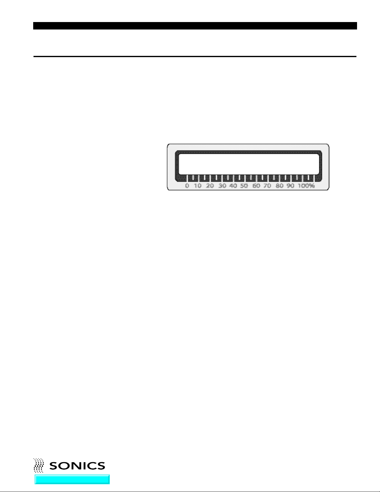
enter parameters will result in the following message being displayed on the
LCD screen:
To return to normal operation and unlock the keypad, power down and
repeat the lock procedure – press and hold the numerical key 7 on power up.
KEYBOARD LOCKED!
NOTE: for external job recall, the keyboard must be locked.
Go To Top Of Document
• • • • • • • • • • • • • • • • • • • • • • • • • • • • • • • • • • • • • • • • • • • • • • • • • • • • • • • • • • • • • • • • • • • • • • • • • • • • • • • • • • • • • • • • • • • • • • • • • • • • • • • • • • • •
I N ST R U C T ION M ANU A L • M OD E L GX T PO W E R S U P P LY
24
Page 26

P R I N T L I N E O U T P U T
At the end of every weld cycle, the power supply sends an ASCII print line
which includes the data for weld time, maximum power and alarm status.
This line can be directed to a printer, a PLC ASCII card or a computer running
any terminal program that will present the information. (The hyperterminal
program is included with any PC under the Accessories/Communications
NOTE: The Print Line
option default is “OFF.”
Switch 5 determines
OFF/ON (see page 48).
NOTE: Use of a printer
causes the cycle to be
extended by
approximately 100 ms.
directory. Note that the communication channel is not bi-directional at this
time; it is an output print line only.)
The transmission settings are fixed at: 19200 bits per second, 8 data bits,
parity = None, 1 stop bit and flow control = None. The cabling and connector
arrangement is set to use a standard 9-pin Null Modem cable, the same
RS232 cable that would be used to connect two PC computers together.
The order of the data is the same for each line and the length of the line does
not change with the values of the data. Line length could be important if a
receiving device is attempting to parse the data for other uses. It means that
the data items are always in the same place and therefore much easier to
remove from the print line.
The end of each print line contains two non-printable characters, a carriage
return followed by a line feed character. These characters are standard
RS232 control characters to position the cursor location to the beginning of
the next line on the screen or print page.
Sample Print line:
1 2 3 4 5 6 7 8
005647 00.48 sec 0.025 in 000130 J 045 %Pmax Alarms T:-- D:-- E:-- J06 -----
005648 00.47 sec 0.025 in 000130 J 045 %Pmax Alarms T:-- D:-- E:-- J06 -----
005649 00.45 sec 0.025 in 000130 J 045 %Pmax Alarms T:-- D:-- E:-- J06 -----
005650 00.48 sec 0.025 in 000130 J 045 %Pmax Alarms T:-- D:-- E:-- J06 -----
005651 00.47 sec 0.025 in 000130 J 045 %Pmax Alarms T:-- D:-- E:-- J06 -----
005652 00.45 sec 0.025 in 000130 J 045 %Pmax Alarms T:-- D:-- E:-- J06 -----
005653 00.48 sec 0.025 in 000130 J 045 %Pmax Alarms T:-- D:-- E:-- J06 -----
005654 00.47 sec 0.025 in 000130 J 045 %Pmax Alarms T:-- D:-- E:-- J06 -----
005655 00.45 sec 0.025 in 000130 J 045 %Pmax Alarms T:-- D:-- E:-- J06 -----
005656 00.49 sec 0.025 in 000130 J 045 %Pmax Alarms T:-- D:-- E:-- J06 -----
005657 00.46 sec 0.025 in 000130 J 045 %Pmax Alarms T:-- D:-- E:-- J06 -----
005658 00.46 sec 0.025 in 000130 J 045 %Pmax Alarms T:-- D:-- E:-- J06 -----
005659 00.47 sec 0.025 in 000130 J 045 %Pmax Alarms T:-- D:-- E:-- J06 -----
Go To Top Of Document
• • • • • • • • • • • • • • • • • • • • • • • • • • • • • • • • • • • • • • • • • • • • • • • • • • • • • • • • • • • • • • • • • • • • • • • • • • • • • • • • • • • • • • • • • • • • • • • • • • • • • • • • • • • •
I N ST R U C T ION M ANU A L • M OD E L GX T PO W E R S U P P LY
25
Page 27

From left to right, the data items show the following information: (for more
detailed information on these items and the print output, refer to the
Appendix)
Position 1 = Customer Resettable Counter (CRC)
Position 2 = Actual weld time
Position 3 = Distance data (applicable for Model GXL only)
Position 4 = Energy data (applicable for Models GXL or GXE only)
Position 5 = Maximum percent power number
Position 6 = Any alarm violations for time
Position 7 = The last job number saved or recalled from job storage memory
Position 8 = Used to indicate a weld cycle termination due to an external
cause
Go To Top Of Document
• • • • • • • • • • • • • • • • • • • • • • • • • • • • • • • • • • • • • • • • • • • • • • • • • • • • • • • • • • • • • • • • • • • • • • • • • • • • • • • • • • • • • • • • • • • • • • • • • • • • • • • • • • • •
I N ST R U C T ION M ANU A L • M OD E L GX T PO W E R S U P P LY
26
Page 28

A U T O M A T I O N I N T E R F A C E & I / O C O N T R O L S
As listed below, there are several interface signals available for operating the
power supply via external digital control lines. These lines are used to initiate
a weld cycle and to monitor the operation (see External I/O Connection
drawing E-3164 in the Appendix).
1. Impulse Input – the impulse input signal is used to initiate a weld cycle
by external contact to ground. The contact must be closed for a minimum
of 50 milliseconds for the welder to recognize the command. Once
initiated, the weld cycle will proceed and the contact should be released.
The contact must be released before the end of the weld cycle; the system
will wait for the impulse contact to open before returning to the ready
screens for data presentation. The impulse input is expecting a dry
contact closure between J2 pin J and K (see Impulse Actuation Cable
drawing E-2703 in the Appendix).
2. Ready Output – when the system is ready to run a cycle, the ready signal
will be true. Any automation system should monitor this signal prior to
initiating a weld cycle with the impulse input. The ready signal will be set
false when a weld cycle begins. It will return true at the end of the weld
after the data has been written to the selected ready screen, the print line
has been sent (if ON) and the alarm signals have been examined and set.
In practice, automation controls should verify that the ultrasonic press is
up and out of the way before loading the next “parts-to-be-welded” into
the fixture and initiating another weld cycle. The ultrasonic system does
not require the press to return “Home” before the next cycle can begin, so
welding could possibly be initiated before the next parts-to-be-welded are
in the ready position.
3. Good Part / Bad Part Outputs – There are two outputs that indicate the
status of the last weld cycle. Both of these status signals are set false at
the beginning of a weld cycle when the ready signal is set false (to indicate
that a cycle is underway). One of these signals will be set true based on
examination of the alarm settings at the end of the cycle. If any alarm
examination points (process limits) have been violated, the Bad Part
Output will be set true. If there are no alarm violations or no limits have
been set, the Good Part signal will be set true.
The Good Part / Bad Part signals are meant to provide an external controller with the information necessary to handle the previously welded part
in the automation environment. If the part is “good” then send it to the
Good part location, if it’s “bad” then recycle or remove it for further
examination.
The Good Part / Bad Part outputs will be valid prior to the ready signal
returning to true at the end of a cycle. The system should use the ready
Go To Top Of Document
• • • • • • • • • • • • • • • • • • • • • • • • • • • • • • • • • • • • • • • • • • • • • • • • • • • • • • • • • • • • • • • • • • • • • • • • • • • • • • • • • • • • • • • • • • • • • • • • • • • • • • • • • • • •
I N ST R U C T ION M ANU A L • M OD E L GX T PO W E R S U P P LY
27
Page 29

signal to qualify these outputs, if ready is true, then the Good Part / Bad
Part outputs are valid.
4. DO4 – There is one extra digital output that is reserved for future
application.
5. DI1, DI2, DI3 and DI4 – Four digital input signals are used for setting an
external job selection when the keyboard is “Locked.” 15 sets of weld
control parameters may be stored in the controller’s battery RAM area.
(see page 21, Job Storage). They may be recalled into the working job
area by setting a binary address code with these digital inputs (see table
below). Valid jobs must exist and have been previously stored via the
keyboard entries. All valid jobs must have a non-zero weld time entry. If a
job does not contain a non-zero time entry, a weld cycle cannot be
initiated.
The keyboard must be locked (see page 23) and the system must be at a
Ready screen for the job address inputs to be active. The inputs are ignored
if these conditions are not set. The keyboard must be locked so that job or
data changes cannot be requested from two different sources – the keypad
and remote address lines – at the same time. Only one source of job change
is allowed: the keyboard (if not locked) or the digital inputs (when the
keyboard is locked).
The job address lines may be changed anytime but must be held stable for
a minimum of 50 ms prior to initiating a weld cycle with the impulse input
command contact. When a job change has been recognized, the system will
momentarily indicate Not Ready for a maximum of 30 ms while the job
settings are recalled from battery backed RAM and the system internals are
reset for a new cycle. The impulse command should be delayed until the
Ready signal returns from the job recall operation if external job setting is
used.
For the quickest possible cycle time, the next job address may be set after
the present weld cycle begins as indicated by the ready signal (false). This
does not affect the present weld cycle as it is already underway and the
settings cannot be changed during the present cycle. They are locked once
a cycle has started. If the job address has been changed during the present
weld to reflect the desired job for the next weld cycle, the recall operation will
happen at the end of the weld cycle before the final Ready indication.
Once Ready is true, the job has already been changed and the system is
Ready to initiate the next cycle. This method extends the weld cycle by 30
ms which are needed to recall the job settings for the next cycle. Depending
on weld times, up to 80 cycles per minute may be achieved including job
changes between each weld (print line must be OFF to achieve this cycle
rate).
Go To Top Of Document
• • • • • • • • • • • • • • • • • • • • • • • • • • • • • • • • • • • • • • • • • • • • • • • • • • • • • • • • • • • • • • • • • • • • • • • • • • • • • • • • • • • • • • • • • • • • • • • • • • • • • • • • • • • •
I N ST R U C T ION M ANU A L • M OD E L GX T PO W E R S U P P LY
28
Page 30
EXTERNAL JOB ADDRESS LINES
0= OFF or open line
1= ON or contact closed
DI1 DI2 DI3 DI4 JOB#
0 0 0 0 No job change
1 0 0 0 1
0 1 0 0 2
1 1 0 0 3
0 0 1 0 4
1 0 1 0 5
0 1 1 0 6
1 1 1 0 7
0 0 0 1 8
1 0 0 1 9
0 1 0 1 10
1 1 0 1 11
0 0 1 1 12
1 0 1 1 13
0 1 1 1 14
1 1 1 1 15
Note that job Code 0 (0, 0, 0, 0) is not a valid job code and does not cause
a job recall operation. Ex: If the last job recalled was Job 10 and the inputs
are set to code 0, then Job 10 still dictates the active job settings.
The digital inputs (DI1, DI2, DI3, DI4) and the digital outputs (DO1, DO2, DO3,
DO4) are set for “Sourcing” as shipped from the factory. They can be
changed to “Sinking” by moving two optical isolator chips (U28/U44 for
inputs; U43/U42 for outputs) on the internal microprocessor controller if
desired. They are completely isolated and floating from the internal power
levels and they are not required to be set the same. The inputs and outputs
are set as a group so all 4 signals will be the same configuration. You may
set one for “Source” and the other for ”Sink” if required by the application
interface. This can eliminate relay logic conversions to save parts and panel
space for some PLC input/output cards. The chips are both optical isolator
chips (PS2501-4 quad optical isolators; digikey part# PS2501-4-ND, as of
this printing) available from most electronic distributors. The isolators are
rated for 30 VDC, 100 ma max – do not connect AC voltage levels!
For more detailed information and to view applicable drawings, refer to
Appendix.
Go To Top Of Document
• • • • • • • • • • • • • • • • • • • • • • • • • • • • • • • • • • • • • • • • • • • • • • • • • • • • • • • • • • • • • • • • • • • • • • • • • • • • • • • • • • • • • • • • • • • • • • • • • • • • • • • • • • • •
I N ST R U C T ION M ANU A L • M OD E L GX T PO W E R S U P P LY
29
Page 31

M A I N T E N A N C E
NOTE: If packing unit
for return shipment, DO
NOT use styrofoam
“peanuts.”
GENERAL
1. Always make sure the power supply has adequate ventilation by keeping
sufficient space around the assembly.
2. Periodically check the ventilation grilles and clean as necessary.
REPAIRS / SERVICE
If problems are encountered, contact our Service Department at 1-800-745-
1105.
It is suggested that a system in need of repair be sent back to the factory
with a written description pertaining to the nature of the problem.
Always contact the factory for return authorization before shipping any
instrument. Include date of purchase, model number, and serial number. For
units not covered by the warranty, a purchase order should be forwarded to
avoid unnecessary delay. Care should be exercised to provide adequate
packing to insure against possible damage in shipment. The system should
be sent with all transportation charges prepaid and return method of
shipment indicated.
Go To Top Of Document
• • • • • • • • • • • • • • • • • • • • • • • • • • • • • • • • • • • • • • • • • • • • • • • • • • • • • • • • • • • • • • • • • • • • • • • • • • • • • • • • • • • • • • • • • • • • • • • • • • • • • • • • • • • •
I N ST R U C T ION M ANU A L • M OD E L GX T PO W E R S U P P LY
30
Page 32

W A R R A N T Y
Go To Top Of Document
Sonics & Materials, Inc., hereinafter referred to as "Sonics", warrants its products
for a period of one year from the date of original shipment against defects in
materials and workmanship under normal installation, use and maintenance as
described in the operating instructions which accompany such equipment.
During the warranty period, Sonics will, at its option, as the exclusive remedy,
either repair or replace without charge for material and labor, the part(s) which
prove upon our examination to be defective, provided the defective unit is
returned to us properly packed with all transportation charges F.O.B. Sonics
dock, Newtown, CT. Warranty period on equipment rentals that are converted to
purchase are deemed to have commenced on the date of original rental
equipment shipment.
Ultrasonic plastics welding horns constructed of titanium or aluminum are
guaranteed against defects for a period of one year from date of shipment.
Sonics will repair or replace a cracked or defective horn once without charge, if
failure occurs within the warranty period.
Ultrasonic plastics welding horns constructed of steel are guaranteed against
defects for a period of ninety days from date of shipment. Sonics will repair or
replace a cracked or defective steel horn once at a charge of 50% of the original
purchase price, if failure occurs within the warranty period.
Ultrasonic metal welding horns constructed of titanium or steel are guaranteed
against defects for a period of one year from date of shipment. Sonics will repair
or replace a cracked or defective horn once without charge, if failure occurs
within the warranty period.
Sonics warrants its ultrasonic converters for a period of one year from date of
shipment with a one-time replacement if a converter proves to be non-repairable.
When customer site service is required, all travel, living and related expenses will
be billed at cost. In-warranty service labor time (including travel time) at the
customers facility is provided Monday through Friday (excluding holidays) from
8:00 am to 5:00 pm. Any in-warranty service time requested outside of these
days and hours will be billed at 150% of Sonics current rate per hour for such
site service work.
LIMITATION OF WARRANTY
This warranty does not apply to items subject to normal wear and tear or, to
equipment or tooling which has been subject to unauthorized repair, misuse,
abuse, negligence or accident. Misuse includes operation of equipment with
tooling that is not qualified for the equipment or tooling not properly installed on
the equipment.
Equipment which, in our judgment, shows evidence of having been used in
violation of operating instructions, or which has had the serial number altered or
removed, will be ineligible for service under this warranty.
• • • • • • • • • • • • • • • • • • • • • • • • • • • • • • • • • • • • • • • • • • • • • • • • • • • • • • • • • • • • • • • • • • • • • • • • • • • • • • • • • • • • • • • • • • • • • • • • • • • • • • • • • • • •
I N ST R U C T IO N M AN U A L • M O D E L GX-SERIES
30
Page 33

For components and parts not manufactured by Sonics but included in Sonics
Go To Top Of Document
manufactured equipment, this warranty shall be limited to the warranty as given
to Sonics by said original component or part manufacturer.
Ultrasonic horns supplied by Sonics are manufactured to exacting specifications
and are tuned to vibrate at a specific frequency. Using an out-of-tune horn will
cause damage to the equipment and may result in warranty nullification. Sonics
assumes no responsibility for converters, horns or fixtures not supplied by
Sonics or for consequential damages resulting from their usage.
Ultrasonic converters showing signs of excessive heat or contamination, such as
but not limited to, oils and moisture, are not covered by this warranty.
Warranty does not apply to ultrasonic horns quoted as prototype, experimental
or of unusual design which, in our judgment are more likely to fail in use.
Warranty does not apply to re-sharpening of ultrasonic blade type cutting or
slitting horns.
Warranty does not apply to knurl pattern wear on ultrasonic plastics and metal
welding horns and tips.
Warranty does not apply to ultrasonic horn or tip face wear when used with
plastics that are molded with fillers, such as but not limited to, glass or talc.
This warranty does not apply to ultrasonic plastics welding equipment, horns or
fixtures where metal-to-metal tooling contact time is in excess of 250
milliseconds.
This warranty does not apply to used or re-built equipment.
This warranty is non-transferable.
Data supplied in Sonics instruction manuals has been verified and validated and
is believed adequate for the intended use of the equipment. If the equipment or
procedures are used for purposes other than those specified herein, confirmation
of their validity and suitability should be obtained in writing from Sonics.
Otherwise Sonics does not guarantee results and assumes no obligation or
liability.
This warranty is in lieu of any other warranties, either express, implied, or
statutory. Sonics neither assumes nor authorizes any person to assume for it any
other obligation or liability in connection with the sale of its products. Sonics
hereby disclaims any warranty or merchantability or fitness for a particular
purpose. No person or company is authorized to change, modify, or amend the
terms of this warranty in any manner or fashion whatsoever. Under no
circumstances shall Sonics be liable to the purchaser or to any other person for
any incidental or consequential damages or loss of profit or product resulting
from any malfunction or failure of this Sonics product.
• • • • • • • • • • • • • • • • • • • • • • • • • • • • • • • • • • • • • • • • • • • • • • • • • • • • • • • • • • • • • • • • • • • • • • • • • • • • • • • • • • • • • • • • • • • • • • • • • • • • • • • • • • • •
I N ST R U C T IO N M AN U A L • M O D E L GX-SERIES
31
Page 34

A P P E N D I X
PRINT LINE OUTPUT DATA ITEMS
Item 1: Using the first line of the sample listing above, item 1 is the
“Customer Resettable Counter” (CRC). It is located at position 1 through
position 6 so the value of 005647 indicates that the last cycle was weld
number 5647 since the last time it was reset to 0 (see page 18).
005647 00.48 sec 0.025 in 000130 J 045 %Pmax Alarms T:-- D:-- E:-- J06 -----
Item 2: The second item sent is the actual weld time from the last cycle –
the time that the ultrasonic generator was running. So 00.48 means that the
generator was ON for .48 seconds. If the weld cycle finished its programmed
weld time, then the following “sec” would have been transmitted as upper
case letters or “SEC.” The “sec” is lower case so the weld cycle was
terminated through some other parameter. The time data is located at
positions 8 through 12 and includes the “.” at position 10. The “sec” label is
located at position 14 through position 16. Space characters are located at
positions 7, 13 and 17.
005647 00.48 sec 0.025 in 000130 J 045 %Pmax Alarms T:-- D:-- E:-- J06 -----
Item 3: Next is the distance data. Distance controls are not available on
Model GXT, so the Distance data will always appear as 0.000 in or 00.00
mm.
005647 00.48 sec 0.000 in 000130 J 045 %Pmax Alarms T:-- D:-- E:-- J06 -----
Item 4: Next is the energy data. Energy controls are not available on Model
GXT, so the Energy data will always appear as 000000J.
005647 00.48 sec 0.025 in 000000 J 045 %Pmax Alarms T:-- D:-- E:-- J06 -----
Item 5: The maximum percent power number is next in line at positions 36
through 38 with a space at 39. This number is the maximum percent of
power developed during the last weld cycle. The label “%Pmax” does not
change case as the control items can for time, distance (Model GXL only)
and energy. It is not a control parameter, just a label for text readability.
005647 00.48 sec 0.025 in 000130 J 045 %Pmax Alarms T:-- D:-- E:-- J06 -----
Go To Top Of Document
• • • • • • • • • • • • • • • • • • • • • • • • • • • • • • • • • • • • • • • • • • • • • • • • • • • • • • • • • • • • • • • • • • • • • • • • • • • • • • • • • • • • • • • • • • • • • • • • • • • • • • • • • • • •
I N ST R U C T ION M ANU A L • M OD E L GX T PO W E R S U P P LY
32
Page 35

Item 6: Any alarm violations for time, distance (Model GXL only) or energy
(Model GXE only) will be sent in the following positions as L or H in place of
the “--” shown in the sample line. The dashes are used to hold the place
when there are no alarm items so the “T:-- D:-- E:--” reading indicates that
there were no alarms during the last weld cycle. (Distance and Energy
controls are not available on Model GXT so those alarms will always print as
“D:-- and E:--.”) The low alarm, high alarm order is always the same for time,
distance and energy (examples: T:L- T:-H or T:LH ). Time alarms are at
positions 57 and 58; distance at positions 62 and 63; and energy at positions
67 and 68. Note that it is possible for a weld cycle to have both high and low
alarms at the same time depending on the alarm settings (see page 17). High
and Low alarms are set and examined independently.
005647 00.48 sec 0.025 in 000130 J 045 %Pmax Alarms T:-- D:-- E:-- J06 -----
Item 7: The next item represents the last job number that was saved or
recalled from the job storage memory. There are 15 jobs numbered 1 through
15 so this item is transmitted as 01 through 15 or “--” if job data has not been
set (first power up). The “J” label is used for readability of the job data
number. When an automation system is using the remote job change option
between weld cycles, the print line can be used as verification of the recalled
job for the last weld cycle. The job data number is located at position 71
through 72.
005647 00.48 sec 0.025 in 000130 J 045 %Pmax Alarms T:-- D:-- E:-- J06 -----
Item 8: The last printable item on the line is a comment position used to
indicate that a weld cycle was terminated by one of several external causes.
Dashes in these positions will be the normal output when the weld cycle is
controlled by weld parameter settings. Four external conditions may be
indicated at the end of the line in positions 74 through 78: “Xstop” indicates
an external stop signal was received (the cutoff command), “MnClr” when
the cycle is stopped because the operator pressed the Clear key during the
weld; “Ovrld” if the system aborts due to ultrasonic overload; and “CkLim” if
the cycle has aborted because the preweld limits failed to find the parts at
the proper position. CkLim will only apply when the distance control is ON
(system was purchased with the distance encoder option – Model GXL).
Go To Top Of Document
• • • • • • • • • • • • • • • • • • • • • • • • • • • • • • • • • • • • • • • • • • • • • • • • • • • • • • • • • • • • • • • • • • • • • • • • • • • • • • • • • • • • • • • • • • • • • • • • • • • • • • • • • • • •
I N ST R U C T ION M ANU A L • M OD E L GX T PO W E R S U P P LY
33
Page 36

Speed Consideration: If ultimate speed is more important to an application
or the system is not using the print line output, it may be turned off with a
switch on the internal processor board behind the front panel. Switch 5 is
normally set OFF, to prevent the system from sending the print line (the
factory default setting). Turn switch 5 ON to have the print line transmitted
after each cycle. The system will respond to the automation start command
(impulse) more quickly with the print line OFF because the message line will
not be compiled or transmitted in this case.
Go To Top Of Document
• • • • • • • • • • • • • • • • • • • • • • • • • • • • • • • • • • • • • • • • • • • • • • • • • • • • • • • • • • • • • • • • • • • • • • • • • • • • • • • • • • • • • • • • • • • • • • • • • • • • • • • • • • • •
I N ST R U C T ION M ANU A L • M OD E L GX T PO W E R S U P P LY
34
Page 37

AUTOMATION INTERFACE & I/O CONTROLS
SOURCE/SINK INPUTS AND OUTPUTS
Vendor terminology and specifications can be confusing as the reference is
easily misinterpreted. Does the vendor send a “Sourcing” signal or do they
mean that an input is ready to receive (or sink) current from an external
source? Some PLC vendors seem to contradict others and the applications
engineer ends up with a bank of relays or pull up/down resistors to switch
the signal type.
When the optical IC is placed into socket U42, the G series outputs (Ready,
Good Part, Bad Part, and the Spare DO) are configured as “Sourcing.” The
isolated transistor collectors must be connected to an external loop supply
(all 4 collectors are connected together; signal name +VDC Source (Input);
pin 18 on I/O Connector J3; cable wire – orn/red). Some PLC’s provide a
DC supply for this purpose, some applications will require a separate
supply.
When the G series output is true or ON, current from the loop supply is
conducted through the output transistor and limiting 100 ohm resistor to the
PLC input card which returns to the loop supply. The PLC input will be ON if
the current is flowing and OFF if the G series output is false or OFF.
Inputs (DI1-DI4) also set for "Source" as factory default.
See schematic drawing on page 40 for more detail.
Go To Top Of Document
• • • • • • • • • • • • • • • • • • • • • • • • • • • • • • • • • • • • • • • • • • • • • • • • • • • • • • • • • • • • • • • • • • • • • • • • • • • • • • • • • • • • • • • • • • • • • • • • • • • • • • • • • • • •
I N ST R U C T ION M ANU A L • M OD E L GX T PO W E R S U P P LY
35
Page 38

SOURCE/SINK DIGITAL I/O CONFIGURATION
The digital inputs and outputs are configured by moving two IC’s on the
control circuit board located directly behind the front panel. Be sure that the
power is OFF and then remove the top cover. The components may be
moved using a small screwdriver to pry the IC’s from the socket strips.
Select the “Source” or “Sink” location and reinstall the components. They
are not required to be set the same – one may be “Source” and the other
“Sink” to best match the required interface signals.
The optical isolator for the Digital Outputs (DO) is shown in the default
“Source” configuration.
The outputs may be switched to “Sink” by moving this IC to the alternate
location as shown below.
The digital inputs
may be
reconfigured in the
same manner.
They are also set
for “Source” as the
factory default as
shown above.
Digital Inputs
shown configured
for “Sink.”
Go To Top Of Document
• • • • • • • • • • • • • • • • • • • • • • • • • • • • • • • • • • • • • • • • • • • • • • • • • • • • • • • • • • • • • • • • • • • • • • • • • • • • • • • • • • • • • • • • • • • • • • • • • • • • • • • • • • • •
I N ST R U C T ION M ANU A L • M OD E L GX T PO W E R S U P P LY
36
Page 39

SINKING OUTPUT TO PLC INPUT DIAGRAM
When the optical IC is placed into socket U43, the G series outputs are
configured as “Sinking.” The isolated transistor emitters must be connected
to the return line of the loop supply (all 4 emitters are connected together;
signal name Voltage Sink Return (output); pin 19 on I/O Connector J3; cable
wire – blu/red).
When the G series output is true or ON, current from the loop supply is
conducted through the PLC input card, the G series output transistor and
100 ohm limiting resistor to the loop supply return line.
See schematic drawing on page 41 for more detail.
PLC OUTPUT TO SINKING INPUT DIAGRAM
When the optical IC for input configuration is placed into socket U28, the G
series inputs (DI1, DI2, DI3, DI4) are configured to receive a “Sinking” input,
a pull down transistor or relay contact to the loop return. The anodes of the
input LEDs must be connected to a user supplied loop supply; +30 VDC max
(all 4 LED anodes are connected together; signal name +VDC Sink-Input; pin
12 on I/O Connector J3; cable wire – black/white).
When the PLC output is true or ON, current from the loop supply is
conducted through the G series opto LED and 2.4 kohm limiting resistor to
the PLC output card which returns to the loop supply. If the PLC output is
ON (conducting), the current is returned to the loop return line and the input
is true or ON. If the PLC output is OFF the G series input is false or OFF.
Go To Top Of Document
See schematic drawing on page 42 for more detail.
PLC OUTPUT TO SOURCING INPUT DIAGRAM
When the optical IC for input configuration is placed into socket U44, the G
series inputs are configured to receive a “Sourcing” input, a high side
transistor or relay contact to the positive loop supply. The cathode side of the
input LEDs must be connected to the return line of the loop supply (all 4
cathodes are connected together; signal name Voltage Source Return –
input; pin 13 on I/O Connector J3; cable wire – red/white).
When the PLC output is true or ON, current from the loop supply is
conducted through the PLC output element to the G series input opto LED
and limiting 2.4 kohm resistor to the return of the loop supply. If the PLC
output is ON (conducting) the G series input is true or ON. If the PLC output
is OFF the G series input is false or OFF.
See schematic drawing on page 43 for more detail.
• • • • • • • • • • • • • • • • • • • • • • • • • • • • • • • • • • • • • • • • • • • • • • • • • • • • • • • • • • • • • • • • • • • • • • • • • • • • • • • • • • • • • • • • • • • • • • • • • • • • • • • • • • • •
I N ST R U C T ION M ANU A L • M OD E L GX T PO W E R S U P P LY
37
Page 40

TWO ISOLATED LOOP SUPPLIES
Two isolated non-regulated 24 VDC supplies (50 ma max) are available on
the digital I/O connector and may be used for the I/O loop power. These are
low level supplies and cannot be used to power relay inputs or outputs! They
should be used for LED indicators or transistor type input cards if the PLC
does not provide low level DC power for this purpose.
The first supply is available on connector J3 pin 1 (+24 VDC isolated supply
#1; cable wire – black) and J3 pin 2 (+24 VDC isolated supply return #1; cable
wire – white). The second supply is on J3 pin 3 (+24 VDC isolated supply #2;
cable wire – red) and J3 pin 4 (+24 VDC isolated supply return #2; cable wire
– green).
See schematic drawing on page 44 for more detail.
I/O TIMING DIAGRAM – AUTOMATION CONTROLS
The cycle begins with the impulse contact to start a cycle (note that the
impulse signal is not part of the configurable inputs and outputs for
compatibility with existing product lines). If the system is using external job
selection, the job address lines must be stable 50 ms prior to the impulse
contact and remain stable until the cycle is underway as indicated by Ready
going low (false). The Good Part/Bad Part lines are also cleared as the cycle
begins.
When the weld cycle is complete, the Good or Bad part signal is set prior to
the system returning to the ready condition. The impulse (and Palm Button
signals) must all be released to complete a cycle and return the Ready
Signal.
See schematic drawing on page 45 for more detail.
Go To Top Of Document
• • • • • • • • • • • • • • • • • • • • • • • • • • • • • • • • • • • • • • • • • • • • • • • • • • • • • • • • • • • • • • • • • • • • • • • • • • • • • • • • • • • • • • • • • • • • • • • • • • • • • • • • • • • •
I N ST R U C T ION M ANU A L • M OD E L GX T PO W E R S U P P LY
38
Page 41

PLC SAMPLE CODE
The following ladder file is a simple demonstration routine to roll the external
job selection from job 1 through 15 then restart at job 1 again. This routine
will switch jobs as fast as possible because the next job code is generated
and set during the previous weld cycle. The job is ready before the previous
cycle is completed.
Go To Top Of Document
• • • • • • • • • • • • • • • • • • • • • • • • • • • • • • • • • • • • • • • • • • • • • • • • • • • • • • • • • • • • • • • • • • • • • • • • • • • • • • • • • • • • • • • • • • • • • • • • • • • • • • • • • • • •
I N ST R U C T ION M ANU A L • M OD E L GX T PO W E R S U P P LY
39
Page 42

When the ultrasonic supply is READY a timer is started to generate the 50
ms impulse command in rung 0. When the timer is finished it will be reset by
rung 0001 so it will be ready to go as soon as the cycle is completed and
ready returns true.
While the timer is timing, output O:3/0 is set causing the ultrasonic system
to begin a new cycle. This is the 50 ms impulse signal (rung 0002).
Once the new cycle has started, the ready signal will be false and the next
job number is sent to the output at output O:1.0. So the address code for the
next cycle is set and stable long before the present cycle is completed (rung
0003).
Rung 0004 generates the next job address code and updates the holding
register, N7:2, with the next job number. If the number is greater than 15, it
gets reset to 1 to start over.
This sample runs round and round as fast as possible limited by the
application time settings, the ultrasonic press movement (gap to the fixture
and parts) and travel distance. Over 80 weld cycles per minute are possible
with very short weld times, higher pressures and shorter press stroke
settings.
Go To Top Of Document
• • • • • • • • • • • • • • • • • • • • • • • • • • • • • • • • • • • • • • • • • • • • • • • • • • • • • • • • • • • • • • • • • • • • • • • • • • • • • • • • • • • • • • • • • • • • • • • • • • • • • • • • • • • •
I N ST R U C T ION M ANU A L • M OD E L GX T PO W E R S U P P LY
40
Page 43
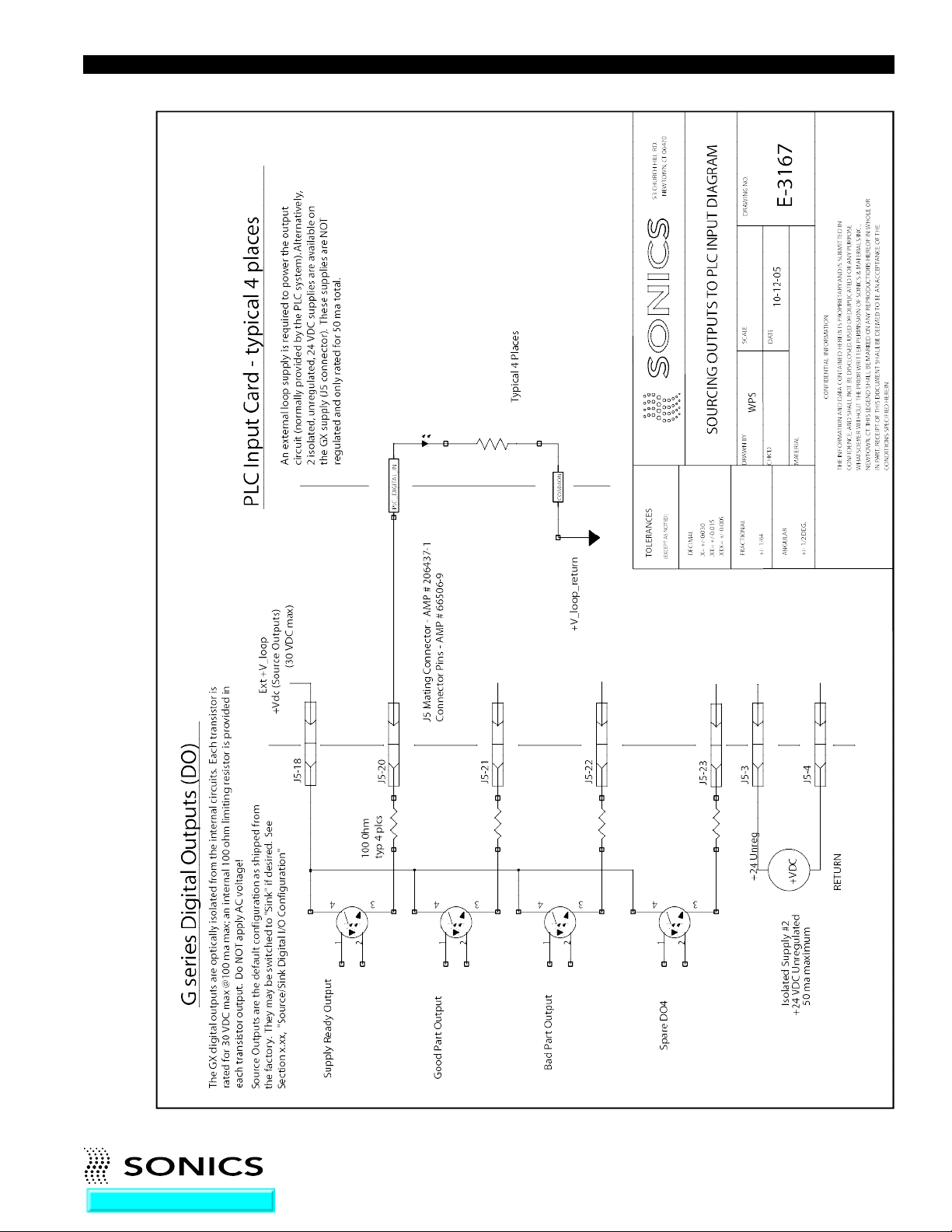
• • • • • • • • • • • • • • • • • • • • • • • • • • • • • • • • • • • • • • • • • • • • • • • • • • • • • • • • • • • • • • • • • • • • • • • • • • • • • • • • • • • • • • • • • • • • • • • • • • • • • • • • • • • •
Go To Top Of Document
I N ST R U C T ION M ANU A L • M OD E L GX T PO W E R S U P P LY
41
Page 44
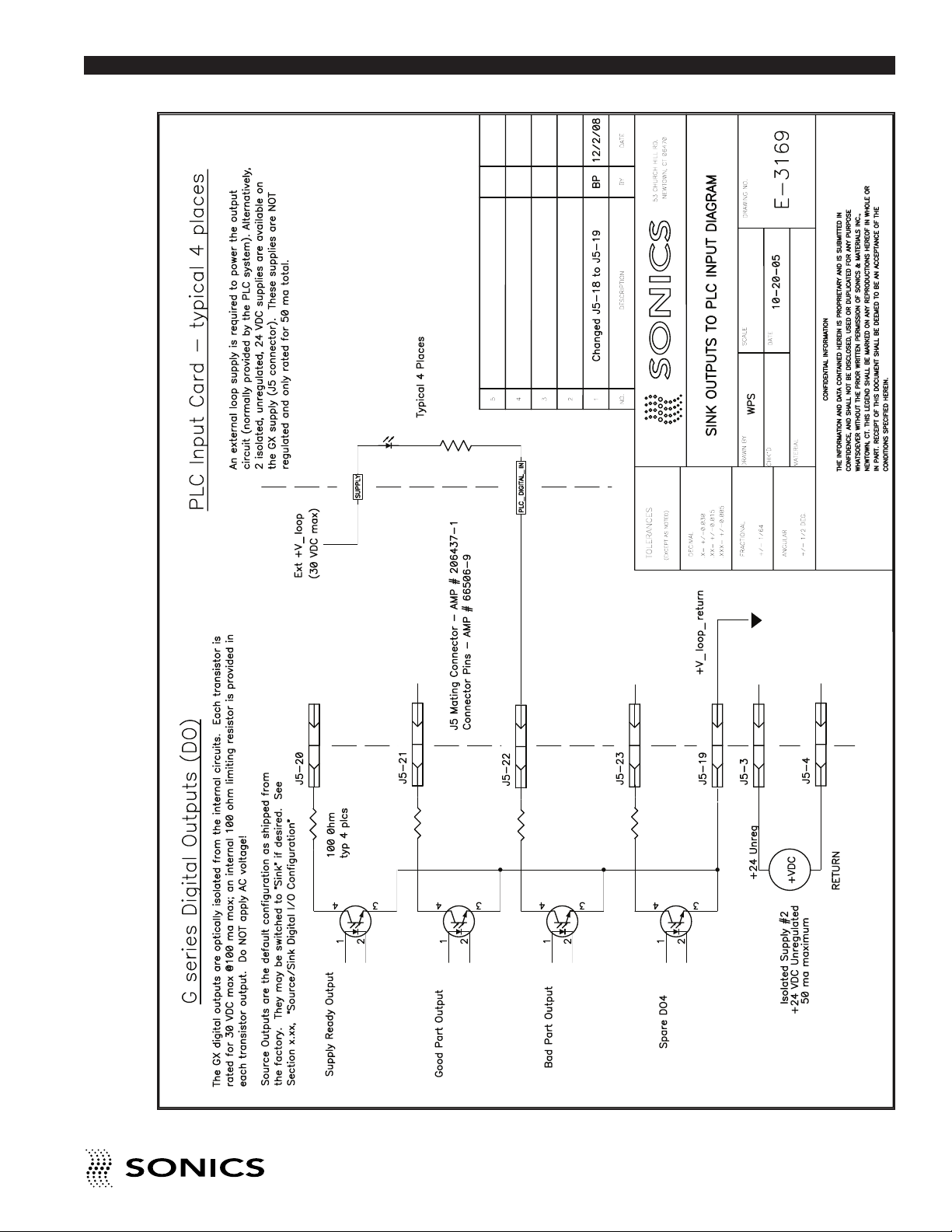
• • • • • • • • • • • • • • • • • • • • • • • • • • • • • • • • • • • • • • • • • • • • • • • • • • • • • • • • • • • • • • • • • • • • • • • • • • • • • • • • • • • • • • • • • • • • • • • • • • • • • • • • • • • •
I N S T R U C T I O N M A N U A L • M O D E L G X - S E R I E S P O W E R S U P P L Y
Page 45
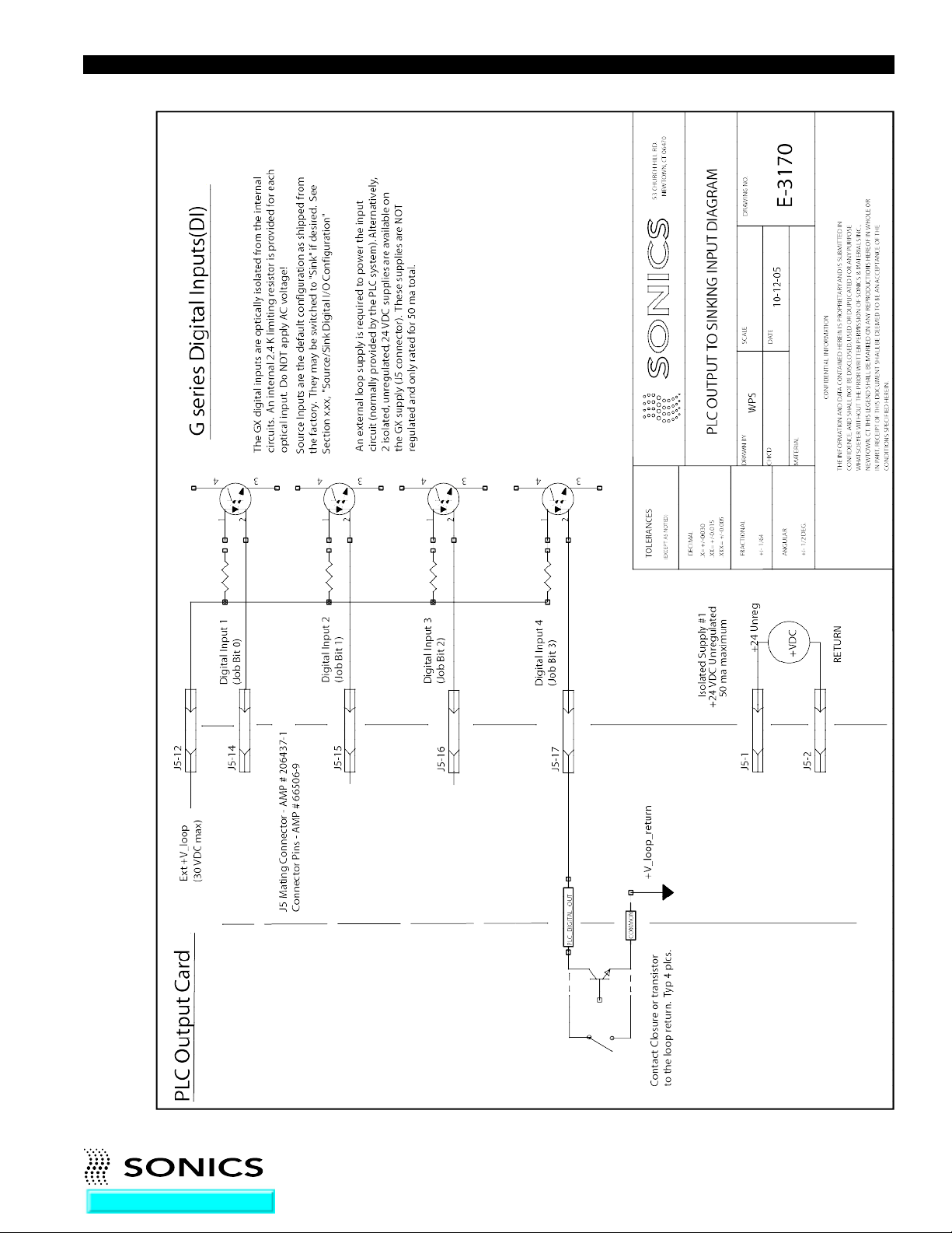
• • • • • • • • • • • • • • • • • • • • • • • • • • • • • • • • • • • • • • • • • • • • • • • • • • • • • • • • • • • • • • • • • • • • • • • • • • • • • • • • • • • • • • • • • • • • • • • • • • • • • • • • • • • •
Go To Top Of Document
I N ST R U C T ION M ANU A L • M OD E L GX T PO W E R S U P P LY
43
Page 46
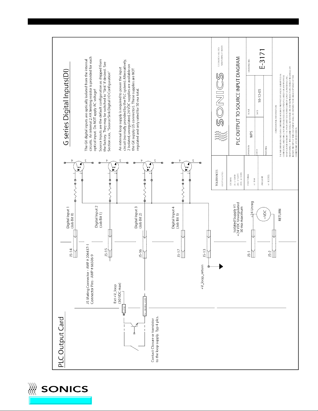
• • • • • • • • • • • • • • • • • • • • • • • • • • • • • • • • • • • • • • • • • • • • • • • • • • • • • • • • • • • • • • • • • • • • • • • • • • • • • • • • • • • • • • • • • • • • • • • • • • • • • • • • • • • •
Go To Top Of Document
I N ST R U C T ION M ANU A L • M OD E L GX T PO W E R S U P P LY
44
Page 47
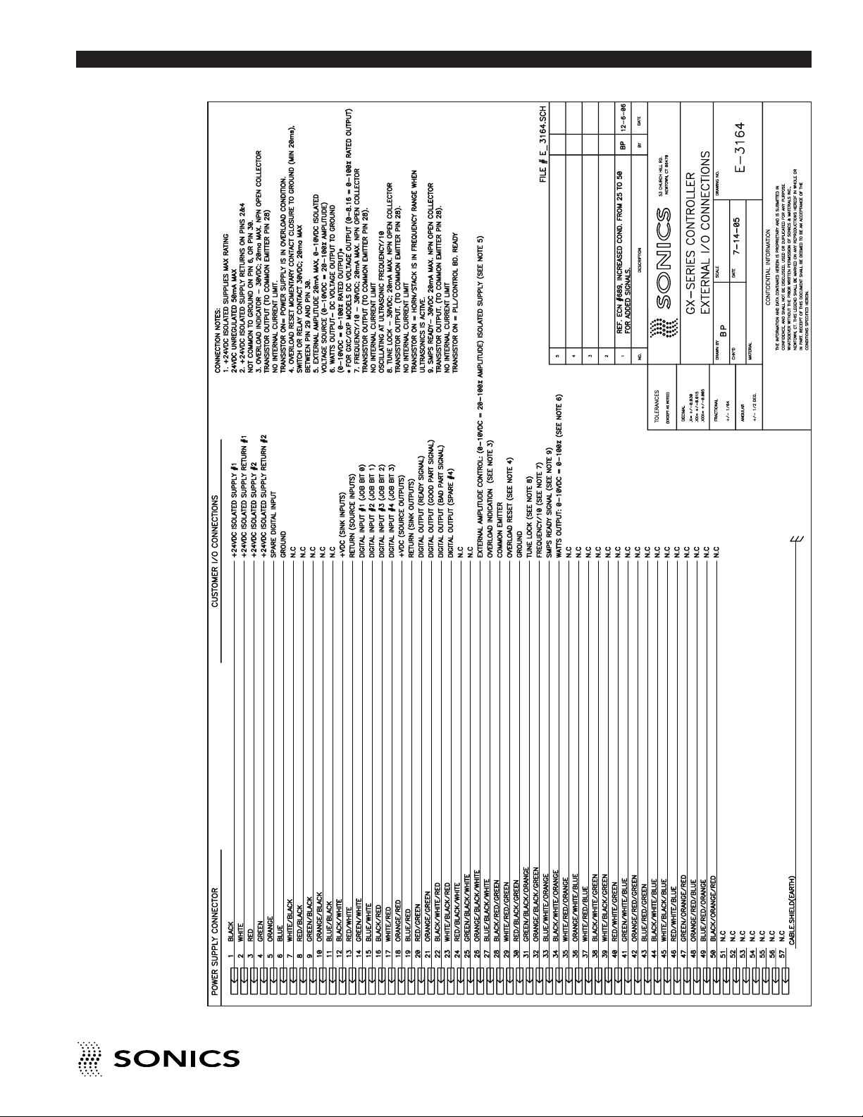
• • • • • • • • • • • • • • • • • • • • • • • • • • • • • • • • • • • • • • • • • • • • • • • • • • • • • • • • • • • • • • • • • • • • • • • • • • • • • • • • • • • • • • • • • • • • • • • • • • • • • • • • • • • •
Go To Top Of Document
I N S T R U C T I O N M A N U A L • M O D E L G X T P O W E R S U P P L Y
45
Page 48
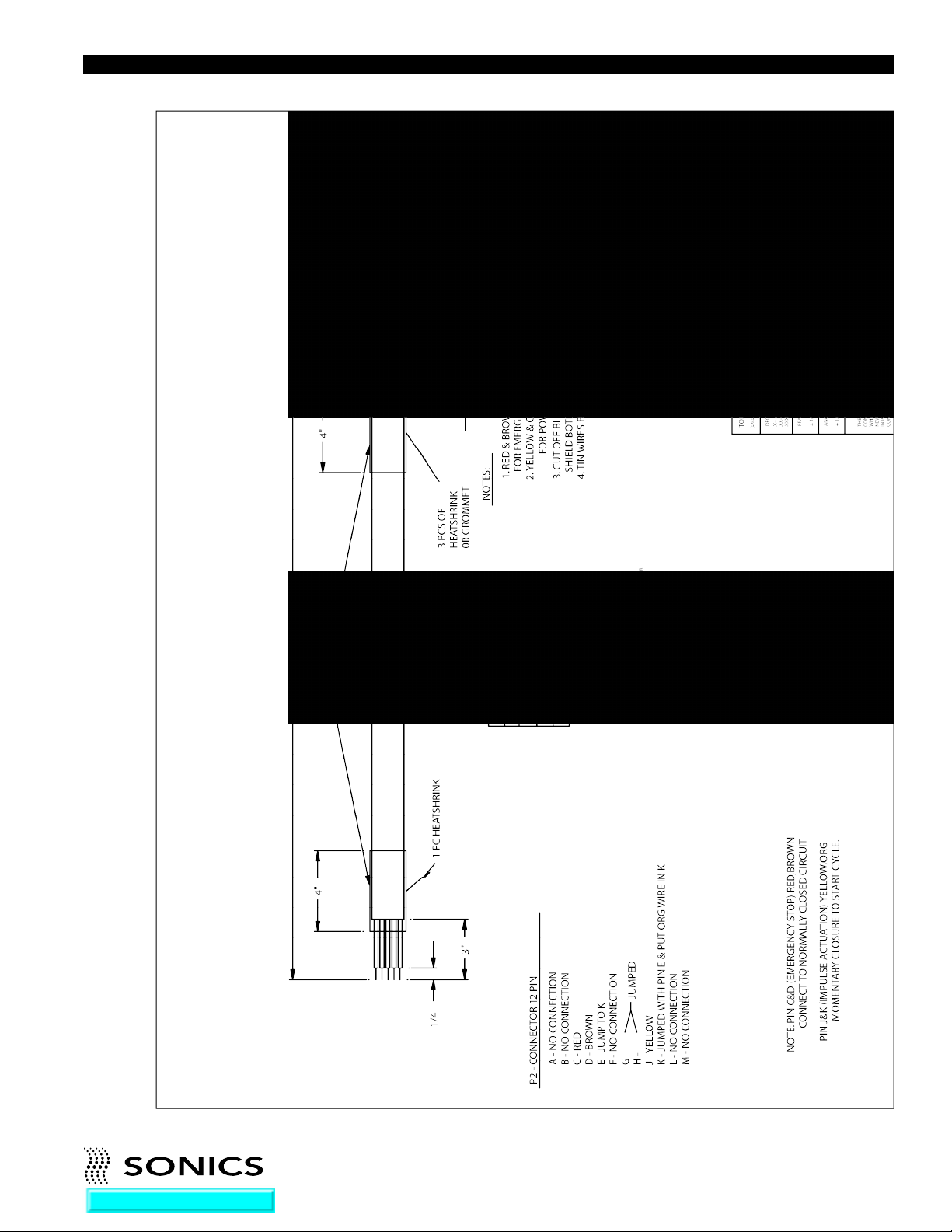
• • • • • • • • • • • • • • • • • • • • • • • • • • • • • • • • • • • • • • • • • • • • • • • • • • • • • • • • • • • • • • • • • • • • • • • • • • • • • • • • • • • • • • • • • • • • • • • • • • • • • • • • • • • •
Go To Top Of Document
I N ST R U C T ION M ANU A L • M OD E L GX T PO W E R S U P P LY
46
Page 49
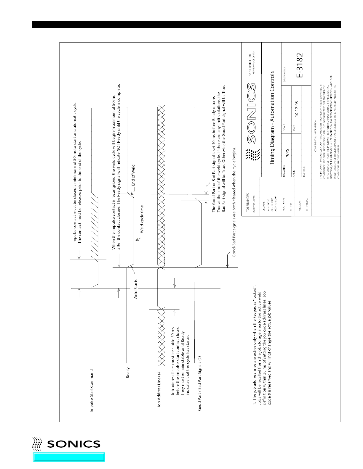
• • • • • • • • • • • • • • • • • • • • • • • • • • • • • • • • • • • • • • • • • • • • • • • • • • • • • • • • • • • • • • • • • • • • • • • • • • • • • • • • • • • • • • • • • • • • • • • • • • • • • • • • • • • •
Go To Top Of Document
I N ST R U C T ION M ANU A L • M OD E L GX T PO W E R S U P P LY
47
Page 50
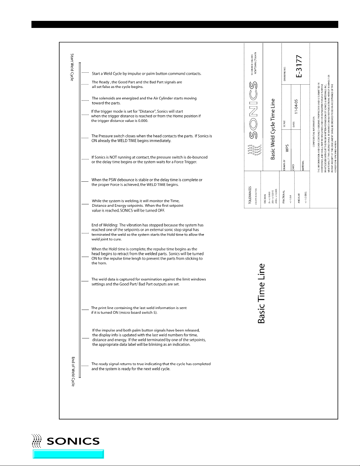
• • • • • • • • • • • • • • • • • • • • • • • • • • • • • • • • • • • • • • • • • • • • • • • • • • • • • • • • • • • • • • • • • • • • • • • • • • • • • • • • • • • • • • • • • • • • • • • • • • • • • • • • • • • •
Go To Top Of Document
I N ST R U C T ION M ANU A L • M OD E L GX T PO W E R S U P P LY
48
Page 51
G-SERIES SWITCHES
SWITCH POS. OFF POS. ON DEFAULT
SW2-1 Program Flash (Production only) Enable-WD (Always on) ON
SW2-2 Cylinder Pot (Future option) Optical Encoder ON
SW2-3 Auto Start Wait for ‘ENTER’ ON
SW2-4 English Metric OFF
SW2-5 Print Line-OFF Print Line-ON OFF
SW2-6 Reserved For Future Expansion
SW2-7 TXT Print Line Future Option OFF
SW2-8 Reserved For Future Expansion
Go To Top Of Document
• • • • • • • • • • • • • • • • • • • • • • • • • • • • • • • • • • • • • • • • • • • • • • • • • • • • • • • • • • • • • • • • • • • • • • • • • • • • • • • • • • • • • • • • • • • • • • • • • • • • • • • • • • • •
I N ST R U C T ION M ANU A L • M OD E L GX T PO W E R S U P P LY
49
 Loading...