


Page 1

User’s Manual for the
Boundary Devices
1
Neon
December 28, 2005
R
board
December 28, 2005 Revision 2.8
Page 2

2
1 Revision History
Date Revision Description
2005-03-20 1.0 First draft
2005-04-03 1.3 Added minidebug instructions
2005-06-11 2.0 Added display config, networking notes
2005-06-27 2.1 Added connector pin-outs (Figure 2)
2005-07-23 2.2 Updated U-Boot version
2005-08-09 2.3 Added notes on mac address command
2005-09-15 2.4 Bumped BSP revision
2005-10-21 2.5 Bumped U-Boot revision
2005-11-07 2.6 Added userland build notes
2005-11-09 2.7 Added rootfs usage notes and list of supported li-
braries
2005-12-28 2.8 Minor updates regarding sshd and userland libraries.
December 28, 2005 Revision 2.8
Page 3

CONTENTS 3
Contents
1 Revision History 2
2 Intended Audience 5
3 Overview of features 5
4 Hardware feature 5
4.1 Layout . . . . . . . . . . . . . . . . . . . . . . . . . . . . . . . 5
4.2 Mounting . . . . . . . . . . . . . . . . . . . . . . . . . . . . . 6
4.3 Connector reference . . . . . . . . . . . . . . . . . . . . . . . 6
4.4 Electrical characteristics . . . . . . . . . . . . . . . . . . . . . 8
5 Software features 9
5.1 Das U-Bo ot . . . . . . . . . . . . . . . . . . . . . . . . . . . . 9
5.1.1 Requirements for building under Linux . . . . . . . . . 9
5.1.2 Requirements for building under Windows with Cygwin 9
5.1.3 General build steps . . . . . . . . . . . . . . . . . . . . 10
5.1.4 Tailoring U-Boot for your application . . . . . . . . . 10
5.1.5 U-Boot Memory layout . . . . . . . . . . . . . . . . . 12
5.1.6 U-Boot Init Script . . . . . . . . . . . . . . . . . . . . 13
5.2 Windows CE . . . . . . . . . . . . . . . . . . . . . . . . . . . 14
5.2.1 Prerequisites and components . . . . . . . . . . . . . . 14
5.2.2 BSP Installation . . . . . . . . . . . . . . . . . . . . . 14
5.2.3 Building the demo . . . . . . . . . . . . . . . . . . . . 15
5.3 Linux Support . . . . . . . . . . . . . . . . . . . . . . . . . . 16
5.3.1 Crosstool Linux Toolchain . . . . . . . . . . . . . . . . 16
5.3.2 Crosstool Embedded (Das U-Boot) Toolchain . . . . . 17
5.3.3 GNUARM binaries . . . . . . . . . . . . . . . . . . . . 18
5.3.4 Kernel 2.4.19 . . . . . . . . . . . . . . . . . . . . . . . 19
5.3.5 Kernel 2.6 . . . . . . . . . . . . . . . . . . . . . . . . . 19
5.3.6 Userland build tool . . . . . . . . . . . . . . . . . . . . 20
5.3.7 Userland libraries and applications . . . . . . . . . . . 22
5.3.8 Notes about userland root filesystems . . . . . . . . . 23
5.3.9 mmcinitrd.u-boot . . . . . . . . . . . . . . . . . . . . . 25
5.3.10 Javascript stuff . . . . . . . . . . . . . . . . . . . . . . 25
5.3.11 Login and SSHD support . . . . . . . . . . . . . . . . 25
6 Development Tools 26
6.1 minidebug . . . . . . . . . . . . . . . . . . . . . . . . . . . . . 26
6.1.1 mdebug . . . . . . . . . . . . . . . . . . . . . . . . . . 27
6.2 JTAG system-level debugger . . . . . . . . . . . . . . . . . . 27
6.2.1 Requirements . . . . . . . . . . . . . . . . . . . . . . . 28
6.2.2 Startup Options . . . . . . . . . . . . . . . . . . . . . 28
December 28, 2005 Revision 2.8
Page 4

CONTENTS 4
6.2.3 Control Keys . . . . . . . . . . . . . . . . . . . . . . . 30
6.2.4 Blast protocol . . . . . . . . . . . . . . . . . . . . . . . 30
6.2.5 Quick-start download and burn . . . . . . . . . . . . . 30
6.3 TeraTerm blast extensions . . . . . . . . . . . . . . . . . . . . 32
6.4 Using U-Bo ot Networking . . . . . . . . . . . . . . . . . . . . 33
7 Configuration Notes 34
7.1 Display configuration . . . . . . . . . . . . . . . . . . . . . . . 34
7.1.1 What display is currently selected? . . . . . . . . . . . 35
7.1.2 What displays are supported...? . . . . . . . . . . . . . 36
7.1.3 Select a supported display . . . . . . . . . . . . . . . . 38
7.1.4 Define and test a new display . . . . . . . . . . . . . . 39
7.1.5 Saving settings to Flash EEPROM . . . . . . . . . . . 40
7.2 Memory size configuration . . . . . . . . . . . . . . . . . . . . 40
7.3 Upgrading U-Boot . . . . . . . . . . . . . . . . . . . . . . . . 41
7.4 Touch Panel Calibration . . . . . . . . . . . . . . . . . . . . . 42
7.5 Ethernet MAC Addresses . . . . . . . . . . . . . . . . . . . . 43
December 28, 2005 Revision 2.8
Page 5

2 Intended Audience
This document aims to provide the information needed to integrate the
R
Neon
board into your application. As such, it addresses both hardware
and software integration.
3 Overview of features
5
The following are highlights of the Neon
R
board.
• Available with Windows Ce or Linux Operating Systems
• Full featured Boot Loader for custom startup
• 400 MHz Intel PXA-255 CPU
• 32 or 64MB SDRAM
• 8 or 32MB Intel StrataFlash (tm) EEPROM
• Silicon Motion SM 501 Graphics Controller
• Active Matrix LCD Support,
• Including Full-Motion Video
• STN Passive LCD Display Support
• 4 or 5-Wire Resistive Touch-Screen Support
• 44KHz Stereo 16-Bit Audio Output, for Headphones or Speakers
• 44KHz Monaural Audio Input (microphone)
• 1 RS-232 or TTL Serial Port
• 1 USB 1.1 Slave Port
• 1 USB 1.1 Master Port
• Built-in 10/100 Ethernet Controller,
• Built-in Interface for Magnetic Stripe Readers and Printers
• MMC Slot for Expanded Storage
• General Purpose I/O for Device Control
• Built-in Switching Power Supply for 5V DC Input
• JTAG Interface
• Customized Versions Available
4 Hardware feature
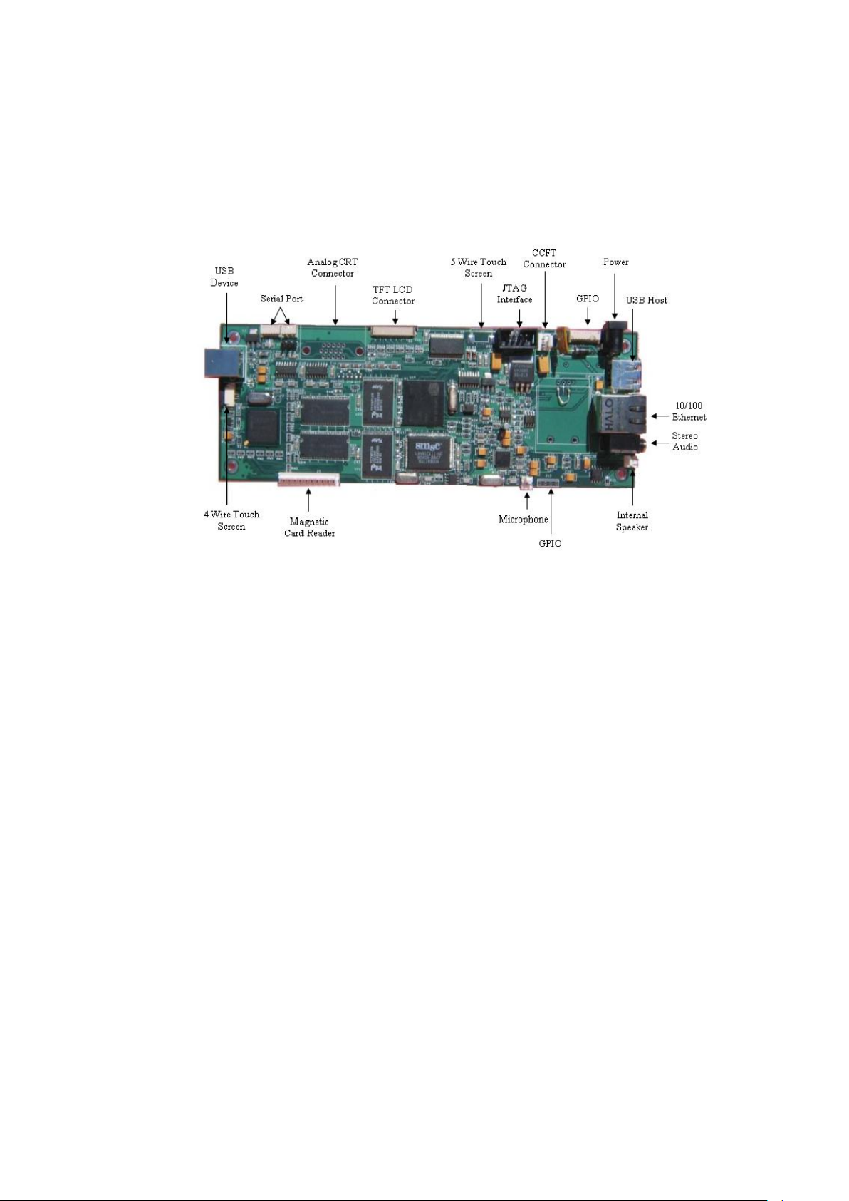
4.1 Layout
As shown in Figure 1, the Neon
options for use in your application. Note that some of these may not be
populated on an evaluation or production board.
December 28, 2005 Revision 2.8
R
board contains a wide variety of I/O
Page 6
4.2 Mounting 6
Figure 1: Neon board
4.2 Mounting
The Neon
6.2” display, to allow for easy mounting.
There are four mounting holes 1/4” from each edge in each of the four
corners, and the holes are 1/8” in diameter.
R
board measures 2.75” by 6.75”, slightly larger than the Hitachi
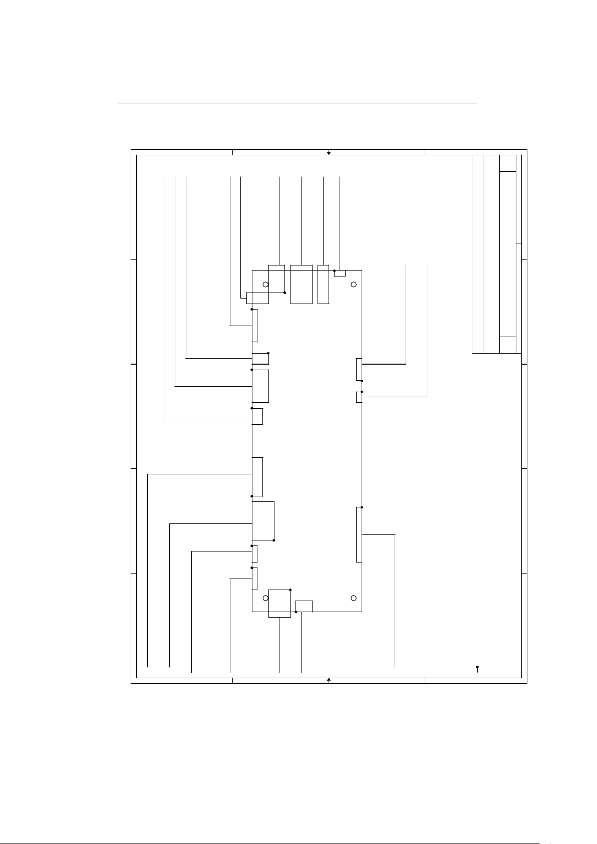
4.3 Connector reference
The following is a list of all connector part numbers used on the Neon
platform for use in identifying mating parts for your application. Note that
Boundary Deviceswill periodically switch vendors for these parts, but will
notify you of any changes that require a new mating part.
R
R
December 28, 2005 Revision 2.8
Page 7
4.3 Connector reference 7
A
A
B
B
C
C
D
D
E
E
4 4
3 3
2 2
1 1
J1J12
J7J14
J22J16
J19
J4J2
J23
J21
J1 J13
J18
J10
J9
J6
J8
1
1
11111
1
1 1
1
1
1
11
INTERNAL SPEAKER PLUS
INTERNAL SPEAKER MINUS
STERIO OUTPUT
PIN1 GENERAL PURPOSE OUTPUT
PIN2 GENERAL PURPOSE OUTPUT
PIN3 GENERAL PURPOSE OUTPUT
PIN4 POWER
PIN 1 MICROPHONE MINUS INPUT
PIN 2 MICROPHONE PLUS INPUT
PIN4 GROUND
PIN 5 GPIO 3 ON CPU UNBUFFERED (ONLY 3.3 VOLT TOLERANT
PIN 7 GPIO 0 ON CPU UNBUFFERED (ONLY 3.3 VOLT TOLERANT
PIN 8 GPIO 0 ON CPU UNBUFFERED (ONLY 3.3 VOLT TOLERANT
PIN 1,2,3,6,9 NO CONNECTION
PIN 10 + 3.3 VOLTS
4 WIRE TOUCH
PIN1 X+
PIN2 Y+
PIN3 X-
PIN4 Y-
USB SLAVE
UART 1
PIN2 NO CONNECT
PIN3 GROUND
PIN4 DATA OUT
PIN5 DATA IN
PIN6 CLEAR TO SEND
PIN1 REQUEST TO SEND
UART2
PIN 1 POWER
PIN2 DATA OUT
PIN3 DATA IN
PIN4 GROUND
HD15 R,G,B ANALOG CONNECTOR
J16 AND J16 ARE RGB OUTPUT FOR TFT PANEL
10/100 ETHERNET
USB MASTER
PIN 2 DRY CONTACT OUTPUT
PIN 3 DRY CONTACT OUTPUT
PIN 4 GPI(GENERAL PURPOSE INPUT)
PIN 5 GPI(GENERAL PURPOSE INPUT)
PINS 6,7,8,9,10 IS GROUND
PIN 1 IS GPO(GENERAL PURPOSE OUTPUT)
INVERTER CONNECTOR
JTAG CONNECTOR
5 WIRE TOUCH SCREEN
PIN1 TOP RIGHT PIN2 TOP LEFT PIN3 BOTTOM LEFT PIN4 BOTTOM RIGHT
PIN 5 SENSE
+5 V INPUT CENTER + BARREL 2.2 MM
NOTE
THE DOT ON EACH CONNECTOR DESIGNATE PIN 1
BOUNDARY DEVICES ALL RIGHTS RESERVED {RevCode}
NEON BOARD IO PIN-OUT
A
1 1Sunday, June 26, 2005
Title
Size Document Number Rev
Date: Sheet of
December 28, 2005 Revision 2.8
Figure 2: Connector Pin-outs
Page 8

4.4 Electrical characteristics 8
Description Manufacturer Part
USB Master FCI 87520-0010B
USB Slave SINGATRON KS-001-BNW
I2C FCI 68897-001
Ethernet Halo HFJ11-2450E
Stereo Audio Singatron 2SJ-43723N13
Backlight inverter Molex 53048-0210
MMC/SD AVX 14 5638 009 511 862
TFT Display
Touch Screen Molex 52207-0590
Serial Port FCI 68897-001
JTAG Molex 53048-0810
4.4 Electrical characteristics
December 28, 2005 Revision 2.8
Page 9

5 Software features
9
As provided by Boundary Devices, the Neon
dows CE 5
R
or Linux.
R
board supports either Win-
To simplify the installation of either, the Das U-Bootboot loader is in-
stalled on our evaluation boards, and two MMC cards are shipped to allow
the use of either operating system.
5.1 Das U-Boot
The Das U-Boot Boot Loader is a full-featured loader for either Linux or
Windows CE that supports a wide variety of options for loading your Operating System and application.
Boundary Devices ships U-Boot both as a binary image and as source
code in the form of a patch that adds support for either Neon or BD-2003
devices.
The binary image may be burned directly to sector zero of the on-board
flash.
The source code will require a set of Linux or Cygwin(Windows) tools
for cross-compilation. The following section will detail the requirements and
steps for building.
5.1.1 Requirements for building under Linux
Since the Das U-Boot project uses GNU tools, most of the required components will generally be available on a GNU/Linux system.
The three pieces which may not commonly be installed are the bzip2
and wget packages and an ARM cross compiler.
Boundary Devices typically uses GCC-2.95.3 to create U-Boot images,
since that matches what we use to build the Linux image to run on the
Neon itself, but the binary distribution of GCC-3.4.3 from GNUARM is a
nice alternative.
5.1.2 Requirements for building under Windows with Cygwin
There are two primary requirements for building under Windows.
The first, Cygwin, provides a s et of Unix utilities under the Windows
operating system. Since the Cygwin installer allows components to be selected individually, the following list shows the requirements for building a
Das U-Bo ot image with Neon
R
support. Note that this list is probably
incomplete, but these should be the only required items which differ from
the Cygwin installation defaults.
December 28, 2005 Revision 2.8
Page 10

5.1 Das U-Boot 10
Base/diffutils
Devel/binutils
Devel/gcc
Devel/make
Devel/patchutils
Utils/bzip2
Web/wget
The second requirement for building is the X-Scale cross-compiler itself.
The GNUARM project provides a wealth of information needed to build a
cross-compiler for ARM processors. Thankfully, it also provides an installer.
As of this writing, Boundary Devices currently uses the GCC-3.4.3 package
for Cygwin.
5.1.3 General build steps
Quick start:
wget http://easynews.dl.sourceforge.net/sourceforge/u-boot/u-boot-1.1.2.tar.bz2
bzcat u-boot-1.1.2.tar.bz2 | tar -xvf wget http://boundarydevices.com/u-boot-2005-10-21.patch.gz
gunzip u-boot-2005-10-21.patch.gz
patch -p0 <u-boot-2005-10-21.patch
cd u-boot-1.1.2
CROSS_COMPILE=arm-elf- make neon_config
-------- U-Boot Boundary Devices Specific Configuration Script -------Choose display type (DA640X240 DA320X240 DA800X480 DA640X480 DA240X320 DA1024X768) []: DA1024X768
answer
Choose hardware type (NEONB NEON BD2003) [NEON]:
answer
Choose software type (WINCE LINUX) []: WINCE
answer
Include minidebug (y n) []: y
answer
CPU speed (100 200 300 400) []: 400
answer
Configuration successful.
make
Explanation.
The first four lines retrieve and extract the Das U-Boot sources and add
support for the Neon
The last two lines configure for the Neon
R
and BD-2003 devices.
R
board itself, and finally, build
a U-Boot binary. The prompts allow you to select the compile-time defaults
for the display, operating system, and CPU speed. Including minidebug
in your U-Boot image allows you to access the debugger while developing
U-Boot scripts.
When complete, you’ll find a file named u-boot.bin in your u-boot-1.1.2
directory.
5.1.4 Tailoring U-Boot for your application
The Boundary Devices patches (uboot neon bd2003.diff) make a variety of
decisions about the boot process which may not match with the needs of
December 28, 2005 Revision 2.8
Page 11

5.1 Das U-Boot 11
your application.
In general, the file u-boot-1.1.2/include/configs/neon.h defines these
choices.
In particular, the distributed copy currently expects a Windows BMP
file named bdlogo.bmp to be present on the MMC card and writes it to the
display, then loads an operating system image from a file named nk.nb0 to
RAM address 0xa0030000 and executes it.
Both of these are defined by the lines which resemble this:
#define CONFIG_BOOTCOMMAND "mmcinit; " \
"fatload mmc 0 a0000000 init.scr ; " \
"autoscr a0000000 ; "
As mentioned previously, the Das U-Boot Boot Loader is a very capable
loader with support for USB and network boot, including BOOTP/DHCP,
and NFS mounting support. Please refer to the Das U-Boot website for
details.
December 28, 2005 Revision 2.8
Page 12
5.1 Das U-Boot 12
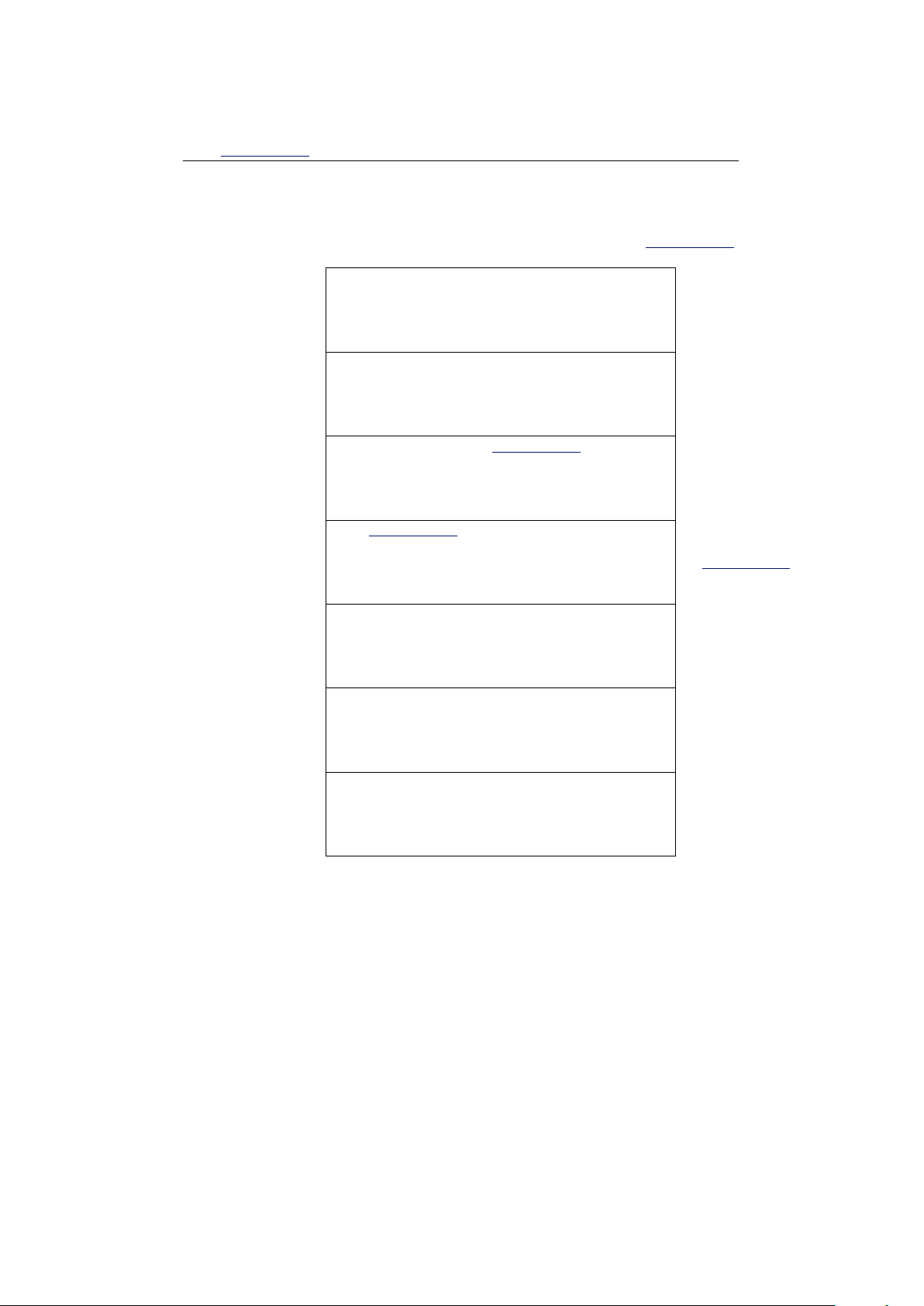
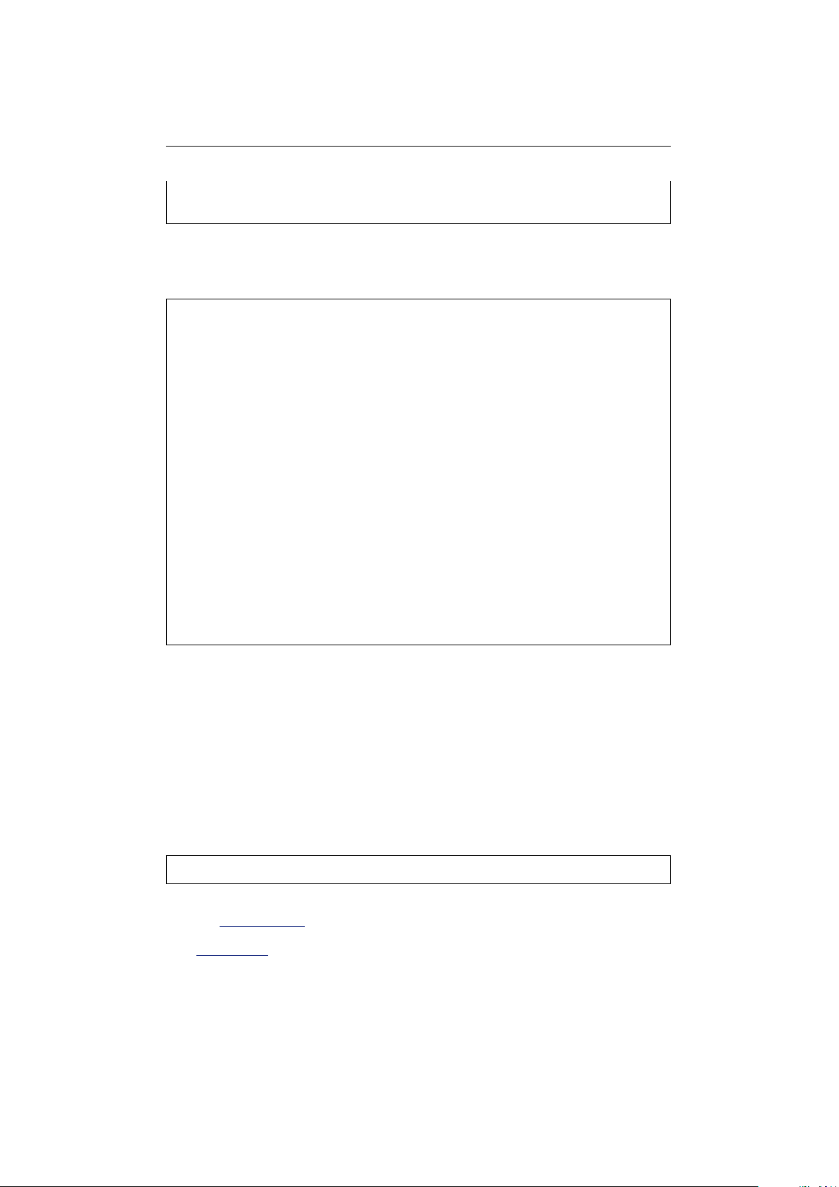
5.1.5 U-Boot Memory layout
The following diagram shows the general layout of RAM within Das U-Boot.
0xA4000000
0xA3FF8000
0xA3FF7FFF
0xA2000000
0xA1FFFFFF
0xA1F00000+
0xA1F00000
0xA1EFFFFF
0xA1EFFFFF0xA1EFFFFF-
0xA1EFFFFF-0xA1EFFFFF--
0xA0000000
32K segment used for page tables.
Unused RAM
Extra space between Das U-Boot and 32MB
boundary
The Das U-Boot image is loaded 1MB below
the 32MB boundary
The heap and stack are allocated in space
preceding the U-Boot image.
1
Frame Buffer for BD-2003
Unused Low RAM
Page Tables
Unused High
Tail of 32MB
Das U-Bo ot image
Heap and Stack
Frame Buffer
Unused Low
December 28, 2005 Revision 2.8
Page 13

5.1 Das U-Boot 13
5.1.6 U-Boot Init Script
The Das U-Boot boot loader comes with scripting facilities in the form of
the Hush parser and the autoscript command. You should notice when first
compiling the package that the B oundary Devices sample uses this to defer
most board initialization to the MMC card. It does this by setting the
CONFIG BOOTCOMMAND environment variable as follows.
#define CONFIG_BOOTCOMMAND "mmcinit; fatload mmc 0 a0000000 init.scr ; autoscr a0000000 "
In English, this instructs U-Boot to initialize the MMC/SD card driver,
load a file named init.scr from the card to address A0000000 (the start of
RAM), and execute the script from that memory address. This little bit of
scripting effectively passes all responsibility of what to do at boot time to
the MMC card.
Think of it as a Das U-Boot version of AUTOEXEC.BAT.
The sample script is defined in u-boot-1.1.2/board/neon/init.script and
performs the following steps.
1. Loads and displays a logo. The script looks for an image file name d
logo.bmp on the MMC/SD card. If found, it displays the logo on the
LCD panel. We recommend that you place a splash image of a size
matching your display on the MMC card. Note that the bitmap must
be an 8-bit color bitmap.
2. Loads and runs Windows CE. Next, the script attempts to load
NK.nb0 from the MMC/SD card and run it.
As mentioned earlier, the initialization has been mostly deferred to the
MMC/SD card, so the compiled script (init.scr) must be placed on the
card itself. The script is compiled using the Das U-Boot mkimage tool
during the U-Boot build process.
The following list is a recap the expected content of the MMC/SD card
when using the Boundary Devices initialization script.
Filename Description
init.scr Compiled initialization script
logo.bmp 8-bit color splash image
NK.nb0 Windows CE image
December 28, 2005 Revision 2.8
Page 14
5.2 Windows CE 14
5.2 Windows CE
As mentioned earlier, the Neon
R
board ships with a runnable Windows CE
5.0 image on MMC card. A Board Support Package is also available and
necessary to tailor the operating system for a given application.
The following sections describe the process of producing an image matching the one shipped with the Neon
R
board.
5.2.1 Prerequisites and components
Most of the tools needed to create a bootable Windows CE 5
for the Neon
R
board are provided by Microsoft. The following is a complete
R
application
list of components and where they may be obtained.
Windows CE 5
R
Microsoft
Embedded Visual C++ 4.0 Microsoft
Embedded Visual C++ Service Pack Microsoft
R
Neon
Board Support Package Boundary Devices
5.2.2 BSP Installation
The Neon BSP is made available as a Windows installer file on the Boundary Devices
website. This file defines a single BSP for the BD2003 and SM501-supporting
variants. Installation consists of running the .msi file.
c:\> wget http://www.boundarydevices.com/bsp20050413.msi
c:\> .\bsp20050413.msi
Please check the Documentation page for details about the latest revision
of the Windows CE BSP.
As a reference tool for the content of the BSP, you should consider using
MSI2XML to view the content.
December 28, 2005 Revision 2.8
Page 15

5.2 Windows CE 15
5.2.3 Building the demo
The Platform Builder project used to construct our sample image may be
found on the Boundary Devices web site.
After installation of the BSP, this project may be copied to a new directory within the WINCE500 PBWorkspaces directory and built using Platform Builder.
C:\WINCE500\PBWorkspaces>md bdWeb
C:\WINCE500\PBWorkspaces>cd bdWeb
C:\WINCE500\PBWorkspaces\bdWeb>wget http://boundarydevices.com/bdWeb.pbxml
--17:37:40-- http://boundarydevices.com/bdWeb.pbxml
Resolving boundarydevices.com... 66.113.228.134
Connecting to boundarydevices.com[66.113.228.134]:80... connected.
HTTP request sent, awaiting response... 200 OK
Length: 45,478 [text/plain]
100%[============================================================================>] 45,478 58.90K/s
17:37:40 (58.90 KB/s) - ‘bdWeb.pbxml’ saved [45478/45478]
C:\WINCE500\PBWorkspaces\bdWeb>.\bdWeb.pbxml
C:\WINCE500\PBWorkspaces\bdWeb>
=> ‘bdWeb.pbxml’
After this is done, you should be able to build the sample WinCE
platform through the Build OS|Sysgen and Build OS|Build and Sysgen
Current BSP menu options.
December 28, 2005 Revision 2.8
Page 16

5.3 Linux Support 16
5.3 Linux Support
The Linux Environment for Boundary Devices boards consis ts of four primary pieces, a toolchain, the kernel and device drivers, a user-space build
tool based on PTXDist and a Javascript runtime used to demostrate the
capabilities of the hardware.
5.3.1 Crosstool Linux Toolchain
Before the kernel and applications can be built, it is first necessary to have
a cross-compiler toolchain.
The following examples show how we at Boundary Devices set up our
toolchains. Please refer to the crosstool site for more complete instructions.
First, you’ll need to download and unpack crosstool;
$ wget http://kegel.com/crosstool/crosstool-0.37.tar.gz
$ tar zxvf crosstool-0.37.tar.gz
As described in the crosstool Quick Start guide, the next step is to choose
a starting point with one of the demo build scripts. We’re currently using
demo-arm-xscale.sh with the following settings (GCC 3.4.3 with Glibc
version 2.3.5):
TARBALLS_DIR=/armArchives
RESULT_TOP=/opt/crosstool
eval ‘cat arm-xscale.dat gcc-3.4.3-glibc-2.3.5.dat‘ sh all.sh --notest
We also build the compiler to use software floating point in user space,
rather than hardware floating point (which traps to the kernel). To do this,
modify arm-xscale.dat and add the --with-soft-float and --without-fp
flags as shown below.
GCC_EXTRA_CONFIG="--with-cpu=xscale --enable-cxx-flags=-mcpu=xscale --with-float=soft"
GLIBC_EXTRA_CONFIG="--without-fp"
Also, we typically change the TARGET to read as follows:
TARGET=arm-linux
because arm-linux-gcc is just too long!
Having completed these edits, you can execute the script as follows:
sh demo-arm-xscale.sh
December 28, 2005 Revision 2.8
Page 17

5.3 Linux Support 17
Note that this will take a looong time2. Find something else to do while
you wait.
When complete, you should find a whole slew of programs in your
/opt/crosstool/gcc-3.4.3-glibc-2.3.5/arm-xscale-linux-gnu/bin/ directory:
-rwxr-xr-x 1 username cvsd 1900724 Jul 18 20:48 arm-linux-addr2line
-rwxr-xr-x 2 username cvsd 1960214 Jul 18 20:48 arm-linux-ar
-rwxr-xr-x 2 username cvsd 3339533 Jul 18 20:48 arm-linux-as
-rwxr-xr-x 2 username cvsd 331791 Jul 18 21:35 arm-linux-c++
-rwxr-xr-x 1 username cvsd 1855723 Jul 18 20:48 arm-linux-c++filt
-rwxr-xr-x 1 username cvsd 331290 Jul 18 21:35 arm-linux-cpp
-rwxr-xr-x 2 username cvsd 331791 Jul 18 21:35 arm-linux-g++
-rwxr-xr-x 2 username cvsd 330887 Jul 18 21:35 arm-linux-gcc
-rwxr-xr-x 2 username cvsd 330887 Jul 18 21:35 arm-linux-gcc-3.4.3
-rwxr-xr-x 1 username cvsd 16265 Jul 18 21:35 arm-linux-gccbug
-rwxr-xr-x 1 username cvsd 102084 Jul 18 21:35 arm-linux-gcov
-rwxr-xr-x 1 username cvsd 2373278 Jul 18 20:48 arm-linux-gprof
-rwxr-xr-x 2 username cvsd 2622683 Jul 18 20:48 arm-linux-ld
-rwxr-xr-x 2 username cvsd 1937609 Jul 18 20:48 arm-linux-nm
-rwxr-xr-x 1 username cvsd 2454999 Jul 18 20:48 arm-linux-objcopy
-rwxr-xr-x 1 username cvsd 2595563 Jul 18 20:48 arm-linux-objdump
-rwxr-xr-x 2 username cvsd 1960209 Jul 18 20:48 arm-linux-ranlib
-rwxr-xr-x 1 username cvsd 429743 Jul 18 20:48 arm-linux-readelf
-rwxr-xr-x 1 username cvsd 1806673 Jul 18 20:48 arm-linux-size
-rwxr-xr-x 1 username cvsd 1780595 Jul 18 20:48 arm-linux-strings
-rwxr-xr-x 2 username cvsd 2454994 Jul 18 20:48 arm-linux-strip
-rwxr-xr-x 1 username cvsd 14395 Jul 18 21:47 fix-embedded-paths
5.3.2 Crosstool Embedded (Das U-Boot) Toolchain
The instructions above can be followed to create a toolchain suitable for
cross-compiling Arm-Linux programs on a host machine. The needs for
building the boot loader are a bit different, though. In particular, the ’glibc’
reference above refers very specifically to userspace ”C” and ”C++” libraries
that defer much of their I/O to the Linux kernel itself through the use of
system calls.
Under Das U-Boot, no such system calls exist. In order to support this,
we need to build a Cross-compiler with a different set of switches. Thankfully, the current crosstool distribution supports that as well through the
use of a small library known as newlib from Red Hat.
The next couple of steps will do just that.
First of all, create a file named
crosstool-0.37/contrib/newlib/arm-elf-newlib-1.12.0.dat
and paste the following content into it.
TARGET=arm-elf
TARGET_CFLAGS="-O2"
BINUTILS_DIR=binutils-2.14
BINUTILS_URL=ftp://ftp.gnu.org/pub/gnu/binutils
NEWLIB_DIR=newlib-1.12.0
NEWLIB_URL=ftp://sources.redhat.com/pub/newlib
2
1 hr, 15 minutes on a 1GHz Athlon w/512MB of RAM
December 28, 2005 Revision 2.8
Page 18
5.3 Linux Support 18
GCC_DIR=gcc-3.4.3
GCC_EXTRA_CONFIG=
Then, create a shell s cript named crosstool-0.37/contrib/newlib/arm-elf.sh with the
following content.
#!/bin/sh
set -ex
TARBALLS_DIR=/armArchives
RESULT_TOP=/opt/crosstool
export TARBALLS_DIR RESULT_TOP
GCC_LANGUAGES="c,c++"
export GCC_LANGUAGES
# You should do the mkdir before running this,
# and chown /opt/crosstool to yourself so you
# don’t need to run as root.
mkdir -p $RESULT_TOP
# Build the toolchain.
# Takes a couple hours and a couple gigabytes.
eval ‘cat arm-elf-newlib-1.12.0.dat‘ sh all-newlib.sh --notest
echo Done.
Next, edit the contrib/newlib/getandpatch-newlib.sh file and replace the line that says:
getUnpackAndPatch ftp://ftp.gnu.org/pub/gnu/gcc/$GCC_DIR.tar.gz ;;
with the following
getUnpackAndPatch ftp://ftp.gnu.org/pub/gnu/gcc/$GCC_DIR.tar.bz2 ;;
Then, run the script like so.
$ time sh arm-elf.sh
5.3.3 GNUARM binaries
The GNUARM site also has binaries for Linux-X86, though we haven’t used
them.
December 28, 2005 Revision 2.8
Page 19

5.3 Linux Support 19
5.3.4 Kernel 2.4.19
Arm-Linux kernel version 2.4.19 Linux kernel patches for ARM processors
PXA Patches Intel PXA support for ARM-Linux
Boundary Devices patches Boundary Devices support
5.3.5 Kernel 2.6
wget http://www.kernel.org/pub/linux/kernel/v2.6/linux-2.6.11.11.tar.bz2
bzcat linux-2.6.11.11.tar.bz2 | tar xvf wget http://boundarydevices.com/boundary-2.6.11.11-2005-11-17.patch.bz2
cd linux-2.6.11.11
bzcat ../boundary-2.6.11.11-2005-11-25.patch.bz2 | patch -p1
cp arch/arm/configs/neon_config ./.config
yes "" | make ARCH=arm CROSS_COMPILE=arm-linux- oldconfig
make ARCH=arm CROSS_COMPILE=arm-linux- uImage
Notes:
Five Wire touch screen support requires setting
Sound|OSS|Multimedia Capabilities Port drivers|UCB 1400|Five wire
(or edit .config and set CONFIG_UCB1400_TS_FIVE_WIRE=y)
December 28, 2005 Revision 2.8
Page 20

5.3 Linux Support 20
5.3.6 Userland build tool
As mentioned before, we at Boundary Devices use a variant of an older
version of the PTXDist tool to keep track of the cross-compilation needs
for various libraries. This allows inter-library dependencies to be expressed,
and also allows the canonical source locations to be used during a build.
This should really be better documented, but the short and simple build
instructions are as follows.
$ wget http://boundarydevices.com/userland_20051126.tar.gz
$ tar zxvf userland_20051126.tar.gz
$ cd userland
$ make menuconfig
-- at a minimum, you’ll need to set an archive path to
a writable directory, and validate your kernel and toolchain
paths.
$ make cramfs
Note that this takes a while (over an hour on a typical machine), but
will result in a cramfs image being created in the userland/ directory.
Also note that installation of the