

Sonex AeroVee 2-into-1 Stainless Exhaust Installation Instructions
P.O. Box 2521 Oshkosh, WI 54903-2521
Tel. (920)-231-8297 Fax. (920)-426-8333
www.aeroconversions.com
Installing the 2-into-1 Exhaust
(052108)
ACV-E01-02 2-into-1 Exhaust System
The 2-into-1 exhaust kit consists of:
Qty. Part No. Description
1....... ACV-E01-20 ..........Exhaust Manifold, Right Side
1....... ACV-E01-21 ..........Exhaust Manifold, Left Side
2....... ACV-E01-22 ..........Exhaust Extension
6....... ACV-E01-23 ..........Springs
8....... ACV-Z01-39 ..........Exhaust Attach Bolts
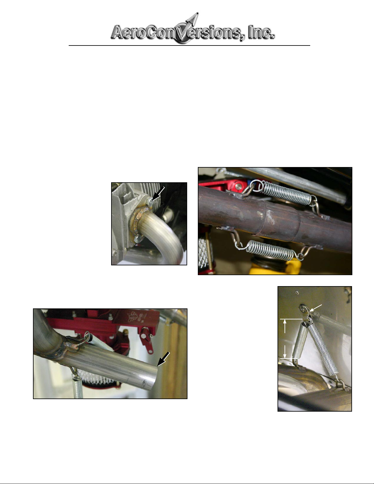
1. Using the supplied
Exhaust Attach Bolts,
temporarily attach the
exhaust manifolds to the
cylinder heads without
exhaust gaskets.
Note: If your cylinder
heads have exhaust studs
installed they will need
to be removed to fit the
2-into-1 exhaust.
2. Slide an extension pipe onto each manifold. It may be
necessary to shorten the length of the exhaust manifold if
the extensions interfere with the firewall. Do not shorten
the expanded portion of the extension pipes.
2
3. After each exhaust manifold has been trimmed to the
proper length, remove the manifolds from the cylinder
heads and re-install them with new exhaust gaskets (supplied with the AeroVee 2180 engine kit).
4. Attach a spring between each pair of spring clips. It may
be necessary to shorten the springs for your particular
installation.
4
1
5. Attach a loop-type line
support clamp (AN742
or equivalent) to the
firewall approximately
3" above the spring
clips on the exhaust
extensions.
6. Attach a spring between
the support clamp and
each exhaust extension.
It may be necessary to
shorten the springs for
your particular installation.
5 & 6
Clamp
installed
on
Firewall
3"
Trim the end of each exhaust manifold (arrow) as needed to
get the exhaust extensions to exit the cowl in the desired location.
AeroConversions, Inc. © 2005 All Rights Reserved.
7. Trim the ends of the exhaust pipes to final length. The
pipes must be long enough to ensure the exhaust gases
exit the cowl, yet pipes which extend too far below the
cowl will add drag and reduce your airspeed.
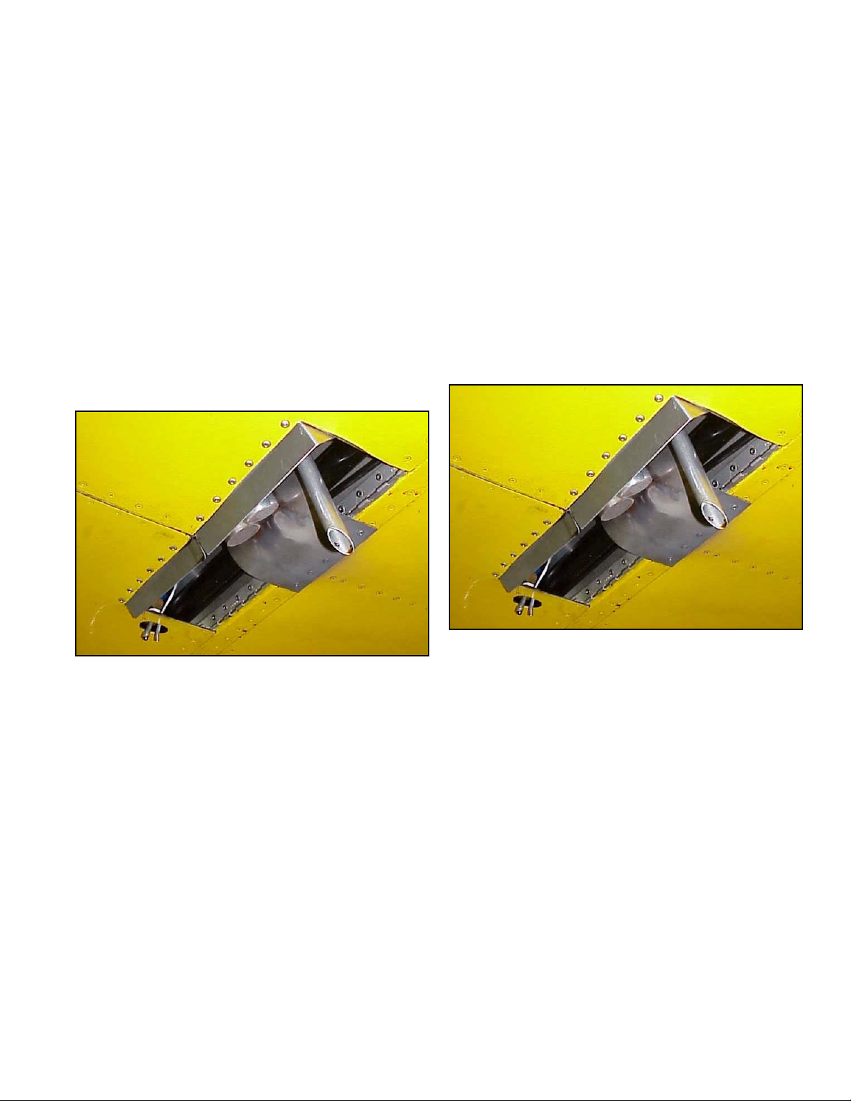
Cowling Considerations
The 2-into-1 exhaust will work with any of the Sonex-provided cowls.
Cowl with Pre-molded (Fiberglass) Exhaust Tunnels.
If your cowling has the premolded exhaust tunnels, the tunnels
must be opened as described in the Sonex/AeroVee Installation Guide. These openings provide the necessary outlet for
the engine's cooling air.
You will also need to make a cowling cut-out at the firewall
large enough for the exhaust pipes to exit. The cutout should
be large enough to clear the exhaust, but not over-sized. If the
cut-out for the exhaust is too large it can degrade engine cooling.
A small deflector lip must also be fitted in front of the exhaust
pipe outlet, and a curved stainless steel deflector may be added
to the bottom of the fuselage skin for the exhaust to spill
against.
Universal Cowl with No Exisiting Exhaust Tunnel
Fitting the 2-into-1 exhaust to a cowling with no existing
outlets is very simple.
A 4" x 12.5" cut-out is made on the lower aft edge of the cowling, where it attaches to the bottom of the firewall. This opening provides both an outlet for the exhaust pipes as well as an
outlet for the engine's cooling air. No other cooling air outlets
should be added to the cowl.
Note: The loss of piano hinge in this area has no impact on the
strength and security of the cowl installation.
An aluminum exhaust lip must be added to the front of the
opening. The lip should be 1" high and rake back 60 degrees
from front to back.
A stainless steel deflector may be added to the bottom of the
fuselage floor to guide and deflect the exhaust gases.
This photo shows the standard outlet for a 2-into-1 exhaust
fitted to a cowl without pre-molded tunnels. If you are fitting a
cowl with premolded exhaust tunnels, this opening must only
be large enough to allow the exhaust pipes to exit. The small
tube in this photo is the oil breather.
Universal Cowl with Aluminum Exhaust Tunnels.
If your universal cowling has aluminum exhaust tunnels installed, you will need to follow the installation outlined above
for "Cowl with Pre-molded (Fiberglass) Exhaust Tunnels".
AeroConversions, Inc. © 2005 All Rights Reserved.
This photo shows the standard outlet for a 2-into-1 exhaust
fitted to a cowl without pre-molded tunnels. The cut-out
measures 4" x 12.5". No additional cowl outlets are needed for
cooling air. The small tube in this photo is the oil breather.
 Loading...