

Page 1
Sonex Aircraft, LLC
PO Box 2521
Oshkosh, WI 54903-2521
(920) 231-8297
Fax: 920-426-8333
www.sonexaircraft.com
________________________________________________________________
SONEX/ELECTRIC INSTRUMENT INSTALLATION NOTES 4 pages
Letter Ref: SNX-ELIN-102708
________________________________________________________________
Congratulations on your Electronic Instrument Purchase. The following notes are
provided for your reference as you set up your Electronic Instrument in your
Sonex, Waiex, or Xenos.
Where any conflict exists between this sheet and the instructions provided with
your Instrument, follow the instructions provided with your instrument:
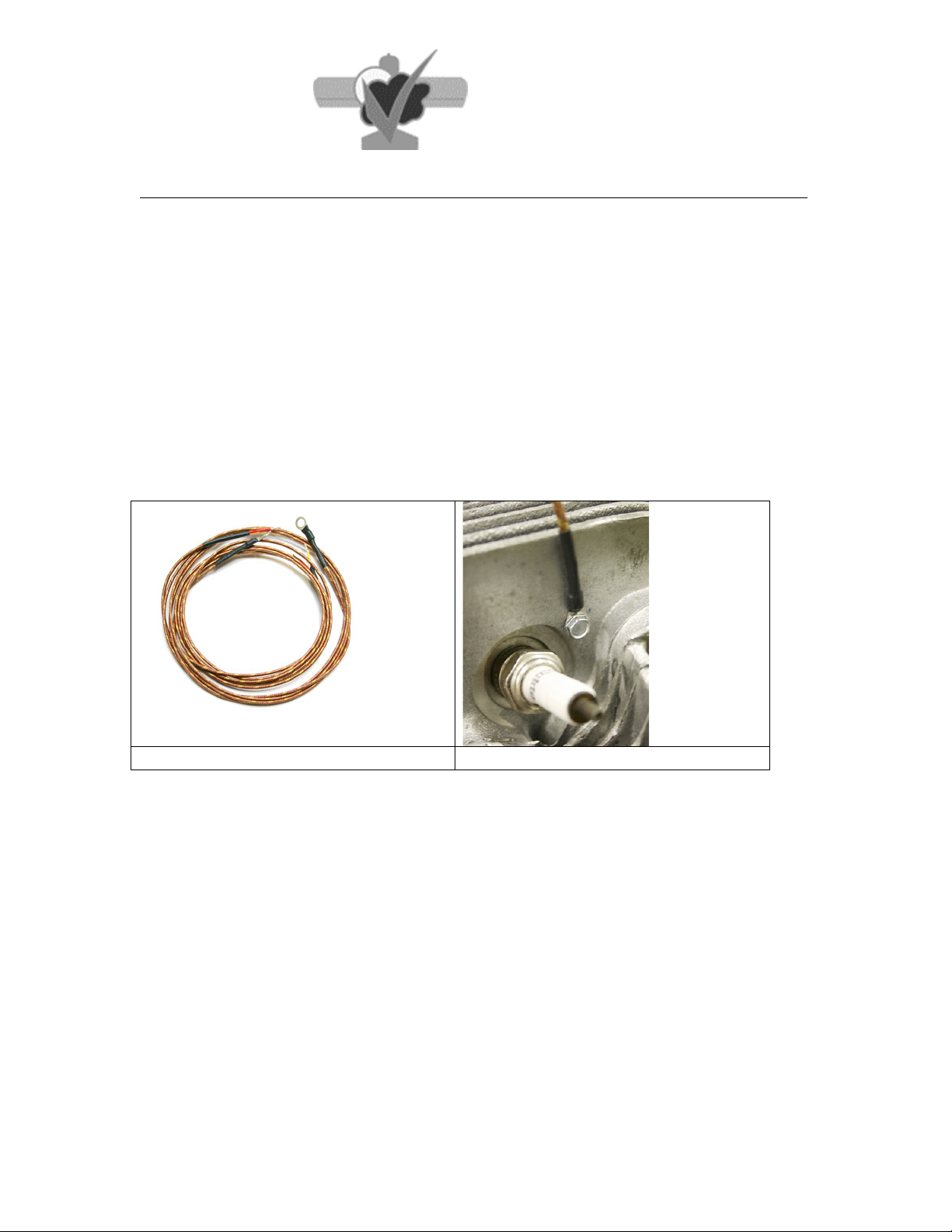
1. CHT Probe Installation: We recommend using the Sonex CHT Probes
available for purchase directly from Sonex Aircraft. Refer to the Engine FWF
Documentation for more information on the monitoring of your CHT’s. Note that
both Type J and Type K versions of these probes are available.
Typical CHT Probe from Sonex
Typical CHT Probe Installation
2. EGT Probe Installation:
Make sure your probe is installed 4 inches down from the top of the exhaust
stack flange. Most EGT Probes are Type K. Refer to the Engine FWF
Documentation for more information on the monitoring of your EGT Probes.
3. Sonex Fuel Level Probe: Your Sonex-Specific Stratomaster Fuel Level Probe
is set up to simulate a Resistive (ohm) output to your instrument as the fuel level
changes. The Sonex-Specific EIS Fuel Level Probe is set up as a Capacitive
output to your instrument. Follow the instructions provided with both the probe
and instrument carefully. For your information, we are providing our factory
installation procedure for Stratomaster Instruments:
Page 2
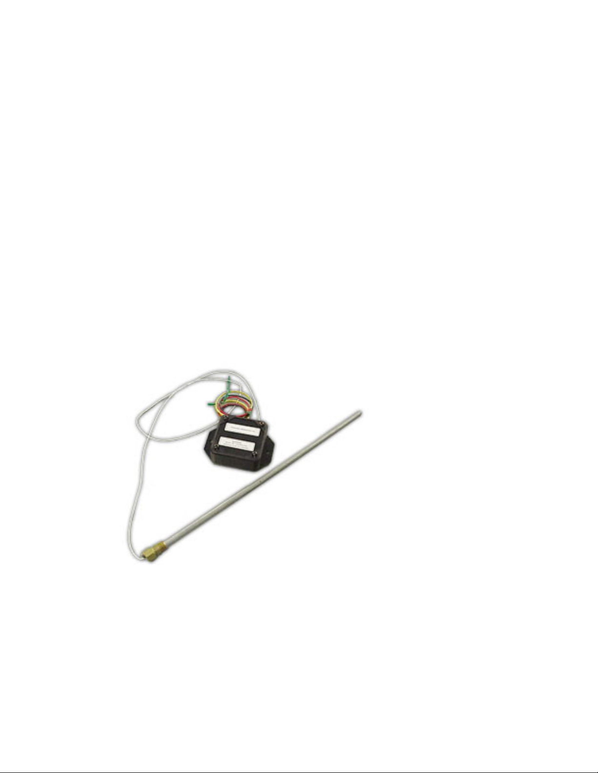
From the Fuel Level Probe "Black Box":
Hook up the Green Wire to the Stratomaster Fuel Level Input on the RDVAC, the
Red Wire to +12V, and the Black Wire to Ground.
The programming in the Stratomaster Unit makes you put 1.3 Gallons in the tank,
which it then will interpret as your empty level. This gives you a reserve of fuel
and additional safety measure of fuel when Stratomaster is reading empty. We
Started with an empty fuel tank and added 2 gallons of fuel and set Fuel Tank
capacity at 1.3 Gallons by hitting "Select" with the Current Output Reading (for
us, this reading was 1920 Ohms). We then set our "fuel low" alarm at 2.0
Gallons, which gives us more than a 1/2 hour reserve once the alarm goes off.
Follow the Instructions on Page 55 of your manual to calibrate your sensor.
Our calibration used the following Resistive Outputs:
0.0 Gallons (1.3 Gallons) 1920 Ohms
2.9 Gallons 1869 Ohms
5.8 Gallons 1804 Ohms
8.9 Gallons 1757 Ohms
11.8 Gallons 1703 Ohms
15.06 Gallons 1651 Ohms
Page 3
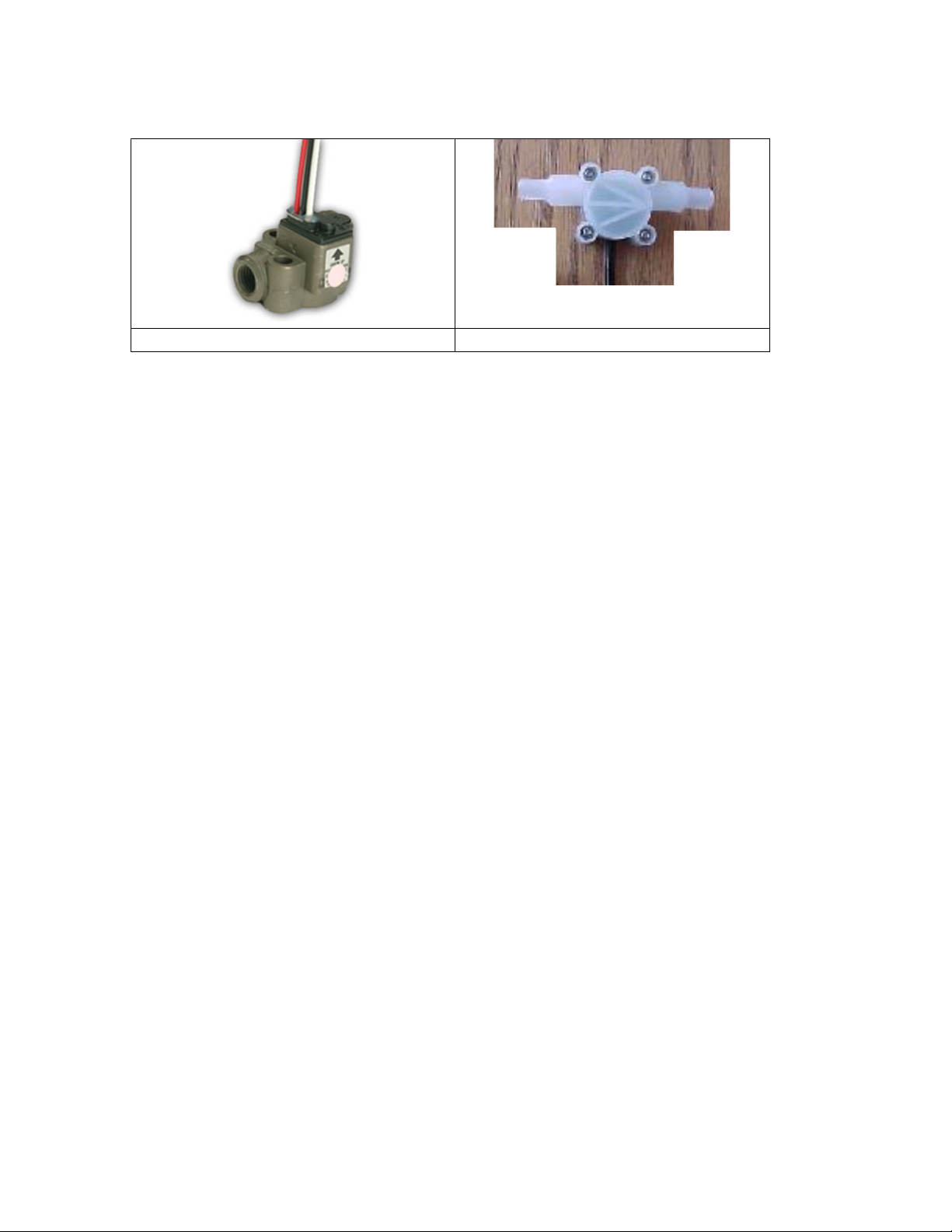
4. Fuel Flow Option: There are two Fuel Flow meters that we have used with
our electronic instruments. A metal “Flo-Scan” unit and a Plastic Unit. See
images below. Sonex recommends that you use the Metal Floscan Unit shown
below.
Metal Floscan Fuel Flow Unit
Plastic Fuel Flow Unit
The Metal Floscan Fuel Flow Installation Instructions can be downloaded from
the Stratomaster or Sonex Web Sites.
The FF sender instructions are relevant to the “Smart Single” Stratomaster FLT-II
Installation. The supplied resistor should be installed between the FLT-II brown
(+5v) wire and the Floscan signal wire, with the Floscan red wire connected to a
12v source.
The plastic unit comes with 4 different jets plastic washer that will be installed on
the inlet side of the unit. These washers restricts the amount of fuel that can flow
through the meter and directs the fuel stream for consistent readings. We
recommend using the 3mm Jet (845) inner diameter (allows over 13.6 gph and
still yields consistent fuel flow readings).
FYI: The recommended “K Factors” for this unit are:
3500 with restrictor jet installed and 1330 with no restrictor installed. Follow the
calibration instructions in the manual to figure out the correct “K factor” Setting for
your unit.
5. Tachometer Set-up: We have set up our tachometer to take a reading off of
one of the “pigtails” exiting the Alternator Stator. We accomplish this by simply
running a wire splice from the pigtail to the “Rev Counter” terminal on the electric
instrument. Only one of the two pigtail wires will give you a reading. If you don’t
get a reading from the first one, try the other one.
The 10-Amp Alternators used on the 2200 Jabiru and 2180 Aero Vee yield 5
pulses per revolution, so the Rev Setup on the Stratomaster Units will be 50. If
you’re using the Grand Rapids EIS, the “EMP” setting will be 5.
The 20-Amp Alternator used on the 3300 Jabiru yields 6 pulses per revolution, so
the Rev Setup on the Stratomaster Units will be 60. . If you’re using the Grand
Rapids EIS, the “EMP” setting will be 6.
As an alternative on the AeroVee Engine, you may put a splice in the “p-lead” of
your primary magentron ignition unit. This will yield 2 pulses per revolution, so
your Rev Setup on the Stratomaster Units will be 20. (EMP=2 for EIS Units)
Page 4

6. Oil Temp Set-up: Set the Oil Temp Probe to “Standard NTC”
7. Oil Pressure Set-up: Set the Oil Pressure Settings on the MGL Instruments to
the following: (Note: On the Jabiru 2200 and 3300, the Oil Pressure wire should
be attached to the terminal labeled “G)
Sender type: automotive, resistive
Resistance: 200 ohms
Resistance INCREASES with pressure
Sender Range: 80 PSI
9.General Grounding Practice: The ground wire for your Stratomaster (and all
your electronic equipment) should be run directly from the negative terminal on
your battery. Special note on RDAC ground (black wire from RDAC): This wire
should be grounded DIRECTLY to the engine block.
Please contact us anytime with questions at the numbers or e-mail below.
Sonex Aircraft, LLC
Phone: (920) 231-8297
Fax: (920) 426-8333
E-mail: [email protected]
http://www.sonexaircraft.com
 Loading...