

Page 1
INSTALLATION INSTRUCTIONS
Introduction
Thank you for purchasing the Sonance Model #91907
fire-rated 6½” Rectangular speaker backcan†.
†The Intertek Listed* fire-rated speaker backcan is a component in the Sonance In-wall Speaker System (WHI Design
Listing DII/PV 60-02), comprised of an Intertek Listed firerated metal backcan (Sonance Model #91907), and a
Sonance Symphony
®
in-wall speaker (or equivalent speaker)
or a metal coverplate to protect the exposed opening.
NOTE: T
HE INCLUSION OF A SONANCE SYMPHONY
®
6½”
RECTANGULAR FOOTPRINT IN-WALL SPEAKER ( OR EQUIVALENT
SPEAKER
) OR A METAL COVERPLATE TO PROTECT THE EXPOSED
OPENING IS REQUIRED IN THIS ASSEMBLY TO ACHIEVE THE
1-HR FIRE-RESISTANCE RATING.
Box Contents
The Backcan box should contain the following:
(1) Intertek Listed Sonance Fire Rated Backcan
(2) Snap2it™ wire clamps
Installation in a Wall
1. Select locations in the wall for the Sonance Symphony
®
In-Wall Speaker per the speaker’s instruction manual.
2. Run speaker wire to desired speaker locations.
N
OTE: ALWAYS CHECK LOCAL BUILDING CODES BEFORE
RUNNING WIRES THROUGH WALLS
.
3. Open one of the knockouts in the Backcan and install one
of the Snap2it™ wire clamps into the open knockout.
N
OTE: A SECOND S NAP2 IT™ WIRE CLAMP IS INCLUDED
FOR DAISY
-CHAINED INSTALLATIONS. A SECOND KNOCK-
OUT ON THE BACKCAN WILL NEED TO BE REMOVED FOR
THIS TYPE OF INSTALLATION
.
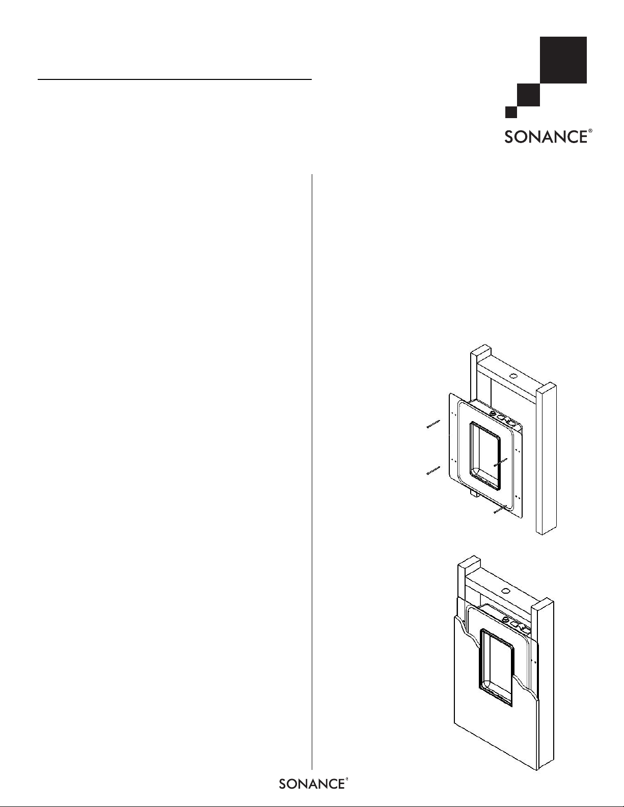
4. Attach the Backcan at the desired wall elevation to the
vertical studs through the pre-drilled holes in the flange of
the speaker Backcan using a minimum of four (4) #8 x 1¼inch long mechanical fasteners: one applied to each corner.
See
Figure 1
.
5. Insert speaker wire through the Snap2it™ clamp and into
the backcan. Leave enough slack to easily connect the
speaker.
6. Cut a hole in the gypsum board‡ to match the rectangular
opening in the Backcan.
‡ Gypsum Board Wall Assembly consisting of any gypsum
board wall assembly, one-hour rated in accordance with
ASTM E119, UL 263, NFPA 251, or CAN/ULC S 101.
7. Apply the gypsum board over the Backcan so that the hole
is aligned with the Backcan opening. See
Figure 2
.
Follow the instructions included with the speaker for the
remainder of the installation, or install a metal face plate to
close the backcan opening.
*See Intertek Directory of Listed Building Products at:
http://etlwhidirectory.etlsemko.com/WebClients/ITS/DLP/Pr
oducts.nsf/$$Search?OpenForm
LISTED FIRE-RATED BACKCAN
FOR SONANCE SYMPHONY
®
IN-WALL SPEAKERS
FIGURE 1: ATTACHING
THE
BACKCAN TO THE
WALL S TUDS
F
IGURE 2: INSTALLING
GYPSUM BOARD ON THE
WALL
(ALIGN CUTOUT
WITH SPEAKER OPENING
ON
BACKCAN)
1
Page 2
2
LISTED FIRE-RATED BACKCAN FOR SONANCE SYMPHONY®IN-WALL SPEAKERS
Installation in a Drop Ceiling
NOTE: WHEN USING THIS LISTED FIRE- RATED BACKCAN IN A
T-BAR CEILING, THE WEIGHT OF THE BACKCAN AND SPEAKER
WILL CAUSE THE CEILING TILE TO SAG
. TO AVOID THIS, WE
RECOMMEND THAT YOU PURCHASE TWO
CADDY
®
SNAP-ON
FIXTURE
/BAR HANGERS
. THE BAR HANGERS CAN BE PUR-
CHASED AT MOST ELECTRICAL SUPPLY COMPANIES
.
Y
OU WILL NEED THE FOLLOWING
CADDY
®
PRODUCTS TO
INSTALL ONE BACKCAN
:
• 2
PCS ELECTRICAL
BOX HANGER (24” SPAN)PART #512
• 2
PCS BOX MOUNTING CLIP PART #BHC
Installing the Backcan
1. Run speaker wire to the desired speaker locations.
2. Open one of the knockouts in the Backcan and install one
of the Snap2it™ wire clamp into the open knockout.
N
OTE: A SECOND S NAP2 IT™ WIRE CLAMP IS INCLUDED
FOR DAISY
-CHAINED INSTALLATIONS. A SECOND KNOCK-
OUT ON THE BACKCAN WILL NEED TO BE REMOVED FOR
THIS TYPE OF INSTALLATION
.
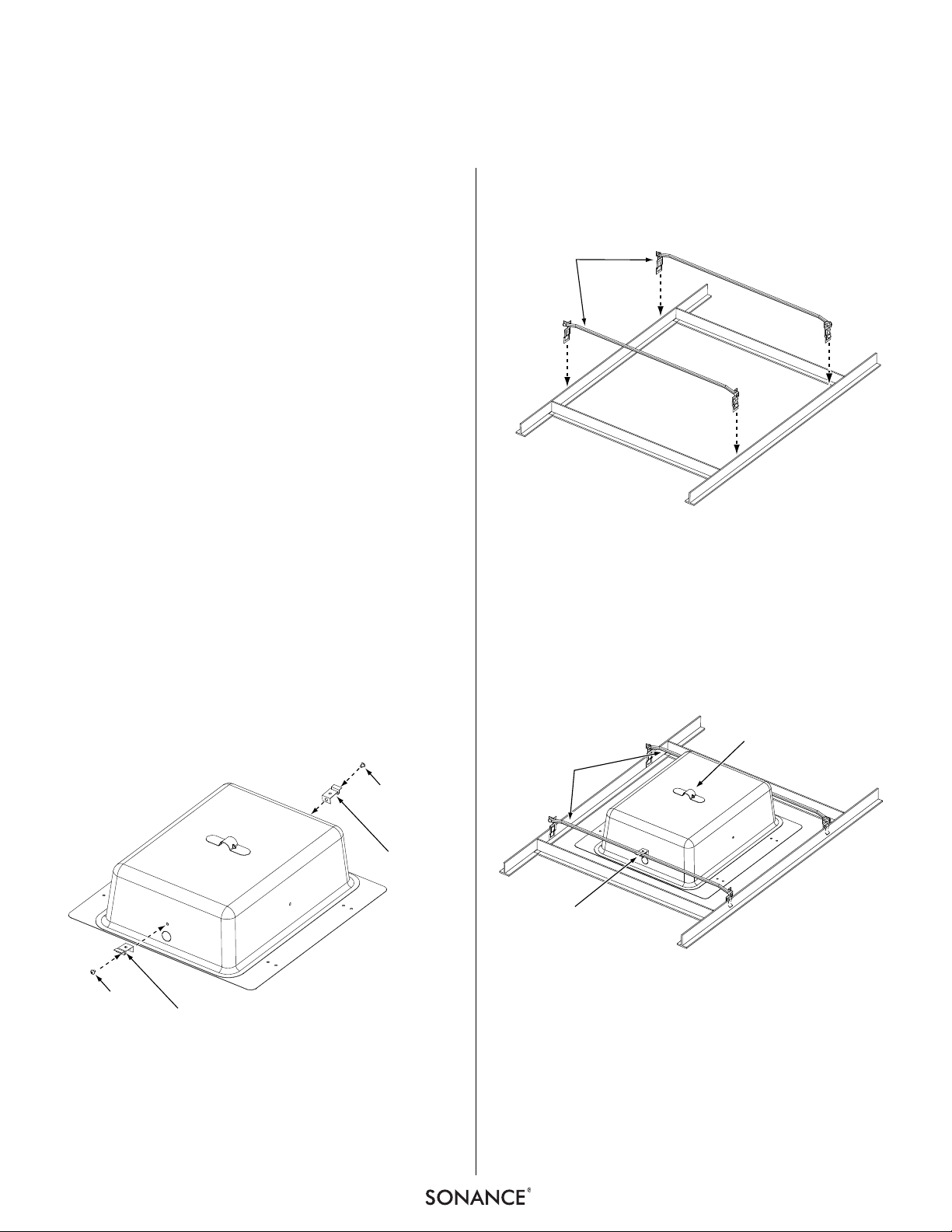
3. Attach the BHC clips to the Backcan ends using the screws
included with the clips (see
Figure 3
).
NOTE: YOU WILL NEED TO REMOVE TWO OF THE ¼” SCREWS
FROM THE ENDS OF THE
BACKCAN.
4. Cut the appropriate size hole in the ceiling tile material.
5. Attach the two 512 electrical box hangers to the T-bar
ceiling grid (see
Figure 4
).
6. Place the Backcan on the cut ceiling tile.
7. Once the Backcan is in place, connect the #512 hangers
to the #BHC clips on the ends of the Backcan
(see
Figure 5
).
8. Insert the speaker wire through the Snap2it™ wire clamp
and into the Backcan. Leave enough slack to easily
connect the speaker.
9. Follow the speaker instructions to mount the speaker into
the Backcan.
FIGURE 3: ATTACHING THE #BHC MOUNTING CLIPS
TO THE
BACKCAN
FIGURE
4: ATTACHING THE #512 HANGERS
TO THE
T-BAR CEILING GRID
F
IGURE 5: CONNECTING THE
#BHC CLIPS
TO THE
#512 HANGERS
#512
ELECTRICAL BOX
HANGERS
SCREW
#BHC
OUNTING
M
CLIP
SCREW
#BHC
OUNTING
M
CLIP
EISMIC
S
HANGER
#512
#BHC
Page 3

3
LISTED FIRE-RATED BACKCAN FOR SONANCE SYMPHONY®IN-WALL SPEAKERS
Technical Assistance and Service
If you have any questions about the operation or installation of this
product, please call our Technical Assistance Department on any
business day at (800) 582-0772 or (949) 492-7777; from 7 a.m. to
5 p.m., PST.
If your product should need repair or service, contact your Sonance
Authorized Dealer for help, or use the following procedure:
1. Prior to calling note the product’s model number, serial number,
purchase date, and the name and address of the dealer where you
purchased the product.
2. Contact our Technical Assistance Department at the above
number(s) and describe the problem the unit is experiencing. If
applicable, they will issue a Return Authorization Number.
IMPORTANT: You must have prior authorization to
return your product to Sonance!
3. If you’re directed to return the unit to Sonance for repair, pack the
unit in its original shipping carton. If needed, you can obtain
replacement packaging from us for a small charge. It is best if you
place the box into an additional outer “overcarton” before shipment to minimize a chance of theft in shipment. Please include a
copy of the original bill of sale inside the package.
4. Contact a package delivery service such as United Parcel Service
or Federal Express to arrange prepaid (not collect) shipping. Do
not use the U.S. Postal Service.
IMPORTANT: Freight collect shipments will be refused.
5. Write the Return Authorization Number on the outside of
the shipping carton.
6. Ship the packaged unit to:
Quality Assurance Department
Sonance
212 Avenida Fabricante
San Clemente, CA 92672-7531
Limited Warranty Coverage (U.S. Only)
Sonance warrants to the original retail purchaser only that
this Sonance product will be free from defects in materials and
workmanship for a period of five (5) years, provided the
product was purchased from a Sonance Authorized Dealer.
Defective products must be shipped, together with proof of purchase,
prepaid insured to the Authorized Sonance Dealer from whom they
were purchased, or to the Sonance factory at the address listed on
this instruction manual. Freight collect shipments will be refused. It is
preferable to ship this product in the original shipping container to
lessen the chance of transit damage. In any case, the risk or loss or
damage in transit is to be borne by the purchaser. If upon examination at the factory or Authorized Sonance Dealer it is determined that
the unit was defective in materials or workmanship at any time during
this warranty period, Sonance or the Authorized Sonance Dealer will,
at its option, repair or replace this product at no additional charge,
except as set forth below. If this model is no longer available and cannot be repaired effectively, Sonance, at is sole option, may replace
the unit with a current model of equal or grater value. In some cases
where a new model is substituted, a modification to the mounting surface may be required. If mounting surface modification is required,
Sonance assumes no responsibility or liability for such modification.
All replaced parts and product become the property of Sonance.
Products replaced or repaired under this warranty will be returned to
the original retail purchaser, within a reasonable time, freight prepaid.
This Warranty does not include service or parts to repair damage
caused by accident, disaster, misuse, abuse, negligence, inadequate
packing or shipping procedures, commercial use, voltage inputs in
excess of the rated maximum of the unit, or service, repair or modification of the product which has not been authorized or approved
by Sonance. This Warranty also excludes normal cosmetic deterioration caused by environmental conditions. This Warranty will be void
if the Serial Number on the product has been removed, tamperedwith or defaced. This Warranty is in lieu of all other expressed warranties. If the product is defective in materials or workmanship as
warranted above, the purchaser’s sole remedy shall be repair or
replacement as provided above. In no event will Sonance be liable
for any incidental or consequential damages arising out of the use or
inability to use the product, even if Sonance or an Authorized
Sonance Dealer has been advised of the possibility of such damages,
or for any claim by any other party.
Some states do not allow the exclusion or limitation of consequential
damages, so the above limitation and exclusion may not apply. All
implied warranties on the product are limited to the duration of this
expressed Warranty. Some states do not allow limitation on the
length of an implied warranty. If the original retail purchaser resides
in such a state, this limitation does not apply.
Exclusions and Limitations
The warranty set forth above is in lieu of all other warranties,
express or implied, of merchantability, fitness for a particular
purpose, or otherwise. The warranty is limited to Sonance products
registered herein and specifically excludes any damage to
loudspeakers and other allied or associated equipment which may
result for any reason from use with this product. Sonance shall, in no
event, be liable for incidental or consequential damages arising from
any breach of this warranty or otherwise. This warranty gives you
specific legal rights, and you may have other rights which vary from
state to state.
Page 4

SONANCE • 212 Avenida Fabricante • San Clemente, CA 92672-7531 • USA
800.582.7777 or 949.492.7777 • FAX: 949.361.5151 • Technical Support: 800.582.0772
www.sonance.com
©2007 Sonance. All rights reserved. Sonance and Sonance Symphony are trademarks or registered trademarks of Dana Innovations.
Due to continuous product improvement, all specifications are subject to change without notice.
For the latest Sonance product specification information visit our website: www.sonance.com
33-4720 09/07
 Loading...