

Page 1

INSTRUCTION MANUAL
S
ONAMP
®
875D SE
8-C
HANNEL
A
MPLIFIER
Page 2

Page 3
3
IMPORTANT: Read all of these instructions before you
install or operate your 875D SE, and save these
instructions for later use.
11.. RReeaadd IInnssttrruuccttiioonnss
— All these safety and operating
instructions should be read before you operate the unit.
22.. RReett aaii nn II nnsstt rruucc tt iioo nnss
— These safety and operating
instructions should be retained for future reference.
33.. HHee ee dd WWaarr nnii nnggss
— All warnings on the unit and in the
operating instructions should be adhered to.
44.. FF oolllloo ww II nnsstt rruucc ttii oonn ss
— All operating and use instructions
should be followed.
55.. WWaatt ee rr aa nndd MMoo iisstt uu rr ee
— The unit should not be used
near water — for example, near a bathtub, washbowl,
kitchen sink, laundry tub, in a wet basement, or near a
swimming pool, and the like.
66.. CC aa rrttss aa nndd SStt aann dd ss
— The unit should
be used only with a cart or stand that is
recommended by the manufacturer.
• A unit and cart combination should be
moved with care. Quick stops, excessive
force, and uneven surfaces may cause
the unit and cart combination to overturn.
77.. CCAA UUTT IIOONN:: TToo pprr ee vveenn tt eellee ccttrr iicc sshh oocckk ,, dd oo nnoo tt uu ssee tthhee
aammppll iiffii ee rr ’’ss ppoo llaa rr iizzeedd ppll uugg wwii tthh aann eexxtteennssi
ioonn ccoorrdd,,
rreecceepptt aaccllee,, oorr ootthheerr oouuttlleett ss uu nnlleessss tthh ee bbllaaddeess ccaann bbee
ffuullll yy iinnsseerrtteedd ttoo pp rreevveenntt bbllaaddee eexxppoo s
suu rr ee ..
88.. VVee nnttii ll aatt iioo nn
— The unit should be situated so that its
location or position does not interfere with its proper
ventilation. For example, the unit should not be situated
on a bed, sofa, rug, or similar surface that may block
the ventilation openings; or be placed in a built-in
installation, such as a bookcase or cabinet, that may
impede the flow of air through the ventilation openings.
99.. HH eeaatt
— The unit should be situated away from heat
sources such as radiators, heat registers, stoves, or other
appliances (including other audio components) that
produce heat.
1100.. PP oo wweerr SS oouu rrcc ee ss
— The unit should be connected to a
power supply only of the type described in the operating
instructions or as marked on the unit.
1111.. GGrroouunn dd ii nngg oorr PPoo ll aa rrii zz aatt ii oo nn
— Precautions should be
taken so that the grounding or polarization means of the
unit is not defeated.
1122.. PP oo wweerr CCoo rr dd PPrr oott ee cctt ii oo nn
— Power supply cords should
be routed so that they are not likely to be walked on or
pinched by items placed upon or against them, paying
particular attention to cords at plugs, convenience receptacles, and the point where they exit from the controller.
1133.. CCll eeaa nn ii nngg
— The unit should be cleaned only as
recommended by the manufacturer.
1144.. NNoonn -- UU ssee PPeerr iioo dd ss
— The power cord of the unit should
be unplugged from the outlet when left unused for a long
period of time.
1155.. OObbjj ee cctt aa nndd LLii qq uu iidd EE nntt rryy
— Care should be taken so
that objects do not fall and liquids are not spilled into the
enclosure through openings.
1166.. DDaammaa gg ee RReeqq uuii rrii nngg SSeerr vv ii ccee
— The unit should be
serviced by qualified service personnel when:
a. The power-supply cord or the plug has been damaged; or
b. Objects have fallen or liquid has been spilled into the
unit; or
c. The unit has been exposed to rain; or
d. The unit does not appear to operate normally or exhibits
a marked change in performance; or
e. The unit has been dropped or the enclosure damaged.
1177.. SSeerrvviicciinngg
— The user should not attempt to service the unit
beyond that described in the operating instructions.
All other servicing should be referred to qualified service
personnel.
Important Safety Information
The lightning flash with arrowhead
symbol, within an equilateral
triangle, is intended to alert the
user to the presence of uninsulated
dangerous voltage within the
product’s enclosure that may be of
sufficient magnitude to constitute a
risk of electric shock to persons.
The exclamation point within
an equilateral triangle is
intended to alert the user to the
presence of important operating and maintenance
(servicing) instructions in the
literature accompanying the
appliance.
TO PREVENT FIRE OR SHOCK
HAZARD, DO NOT EXPOSE THIS APPLIANCE TO RAIN OR MOISTURE. THE
APPLIANCE WHALL NOT BE EXPOSED
TO DRIPPING OR SPLASHING. NO
OBJECTS FILLED WITH LIQUIDS SHALL
BE PLACED ON THE APPLIANCE.
TO REDUCE THE RISK OF ELECTRIC
SHOCK, DO NOT REMOVE COVER OR
BACK. NO USER-SERVICEABLE PARTS
INSIDE. REFER SERVICING TO AUTHORIZED SERVICE PERSONNEL.
CAUTION:
Page 4
4
SONAMP®875D SE 8-CHANNEL AMPLIFIER
Introduction
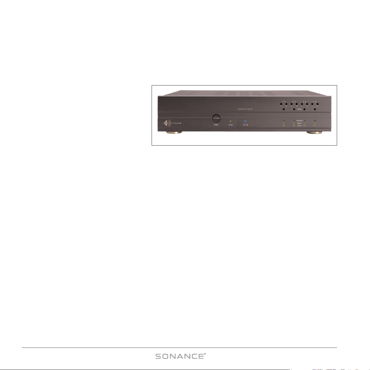
Thank you for purchasing the Sonance Sonamp®875D SE power amplifier. The 875D SE will provide you with many years
of home entertainment enjoyment. This manual will teach you all about your new amplifier’s many innovative features and
will show you how to get the very best performance from your amplifier. Please read it thoroughly.
Design and Features
Power
The Sonamp®875D SE is a hybrid amplifier that
combines digital amplification with analog
power supplies. Its Class T amplifier with Digital
Power Processing™ technology delivers the
high efficiency of digital (Class D) amplification
with the superior sound quality of analog (Class
AB) amplifiers. This allows the 875D SE to deliver high power (75 watts RMS per channel @ 8 ohms x 8 Channels) in an
exceptionally small (2U rack height) package. And unlike conventional digital amplifiers which cannot operate in bridged
configuration, the 875D SE’s Class T circuitry allows you to operate it with any of its four pairs of channels in a bridged
mode, providing 300 watts x 4 channels into an 8-ohm load. Four independent power supplies (one for each zone) supply
plenty of current, so each zone can maintain full performance regardless of how hard any other zones are being driven.
BBE®Sound Enhancement
The Sonamp 875D SE incorporates BBE®Sound Enhancement. The BBE process improves the presence and detail of speakers,
especially at lower listening volumes, improving the sound quality of your music — especially distributed audio systems
playing background music. BBE also restores clarity and definition (or focus) to spoken voices, which makes paging
systems easier to understand without having to run them at high volumes. Each zone in the 875D SE has individual
controls that let you set the BBE enhancement for that zone to +9dB, +6dB or OFF. The factory default setting is +6dB.
Inputs and Triggers
Multiple audio input connections (DIRECT, L/R & AUX) and buffered line outputs make your 875D SE extremely flexible, so
you can connect the amplifier in a variety of ways depending on your particular system’s configuration. The Illustrations on
pages 15 – 20 show the 875D SE being used in several different possible system configurations. Each zone has its own 12V
input and output triggers and defeatable auto-on signal sensing that can automatically turn the amplifier ON. Recessed
front-panel controls are tamper-resistant, and let you adjust each channel’s input level and each zone’s auto-on sensitivity.
Front-panel LEDs tell you if the 875D SE’s power is on or off, if each Zone is on or off, and the BBE status and fault status
for each zone.
Serial Control Capability
The 875D SE’s RS-232 connection lets you use a variety of 3rd-party serial control systems to control the amplifier.
The serial control provision lets you control almost all of the 875D SE’s functions, and also lets you monitor the amplifier’s
operation from a remote location.
Figure 1: Sonamp®875D SE
Page 5
SONAMP®875D SE 8-CHANNEL AMPLIFIER
5
ON
ON
ON
ON
OFF
OFF
OFF
OFF
ON
ON
ON
ON
OFF
OFF
OFF
OFF
ON
ON
ON
ON
OFF
OFF
OFF
OFF
ON
ON
ON
ON
OFF
OFF
OFF
OFF
ON
ON
ON
ON
OFF
OFF
OFF
OFF
ON
ON
ON
ON
OFF
OFF
OFF
OFF
ON
ON
ON
ON
OFF
OFF
OFF
OFF
ON
ON
ON
ON
OFF
OFF
OFF
OFF
L
R
A
A.C. ON
AUTO ON
LRLRLRLR
1 – 2 3 – 4 5 – 6 7 – 8
PROTECTION
BBE ON
ACTIVE
ACTIVEPOWER
BBE CONTROL
BUS
INPUT
OUTPUT
BUFFERED
DIRECT
LEFT
RIGHT
AUX
DIRECT
LEFT
RIGHT
AUX
DIRECT
LEFT
RIGHT
AUX
DIRECT
LEFT
RIGHT
AUX
DIRECT
LEFT
RIGHT
AUX
AUTO
VOLT
AUTO
VOLT
AUTO
VOLT
AUTO
VOLT
TRIGGER MODE
DIRECT
LEFT
RIGHT
AUX
DIRECT
LEFT
RIGHT
AUX
DIRECT
LEFT
RIGHT
AUX
BBE CONTROL
INPUTS 5 – 24V AC–DC
EXTERNAL TRIGGER
INPUTS 5 – 24V AC–DC
TRIGGER OUTPUTS
12VDC
OFF
LOW
OFF
LOW
OFF
LOW
OFF
LOW
ON
HIGHONHIGHONHIGHONHIGH
1/2 3/4 5/6 7/8
+ 1 – – 2 + + 3 – – 4 + + 5 – – 6 + + 7 – – 8 +
CH
CH1 CH2
NORMAL BRIDGED NORMAL BRIDGED
ALL CH
CH
RS-232
1/2 3/4 5/6 7/8
CH 1/2
CH 3/4
CH 5/6
CH 7/8
OFF ON
ALL
S/N
1/2 3/4 5/6 7/8
+ – + – + – + – + –
BRIDGED
8Ω MIN
BRIDGED
8Ω MIN
BRIDGED
8Ω MIN
BRIDGED
8Ω MIN
NORMAL BRIDGED NORMAL BRIDGED
+ – + – + – + –
(BRIDGED)
CH3 CH4
(BRIDGED)
CH5 CH6
(BRIDGED)
CH7 CH8
(BRIDGED)
CAUTION: REPLACE WITH THE
SAME TYPE AND RATING FUSE
SONAMP® 875D SE
120V–60Hz 1200W
–FUSE T10AL 250V
RS-232
RS-232
RS-232
RS-232
1243
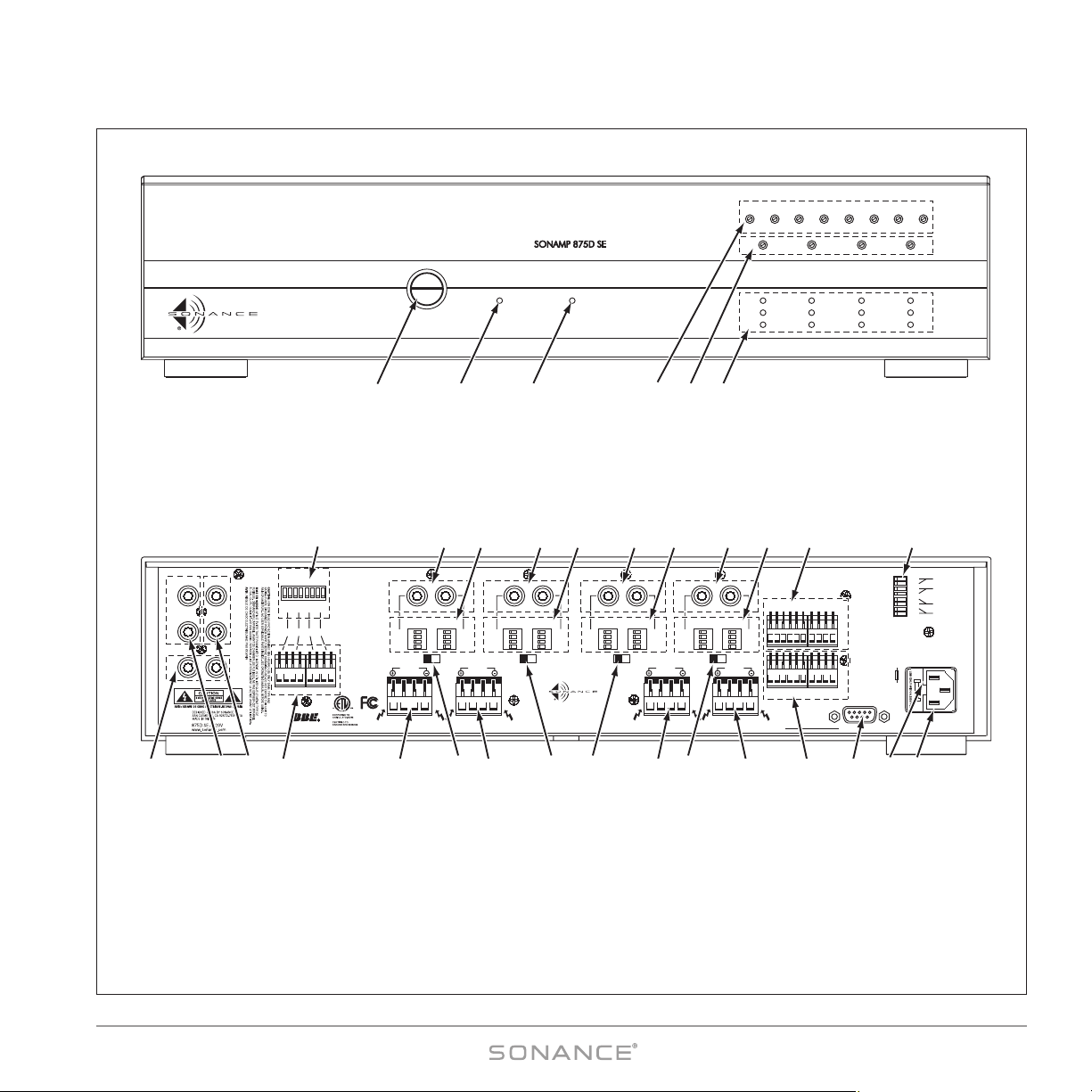
1. Power Button
2. Active LED
3. AC On LED
7. Aux Input & Buffered Output
8. Left & Right Bus Inputs
9. Left & Right Buffered Outputs
10. BBE External Control Input Connections
(Zones 1 – 4)
11. BBE Control Setting DIP Switches
(Zones 1 – 4)
12. Speaker Connectors (Zones 1 – 4)
13. Bridging Switches (Zones 1 – 4)
14. Direct Input Connections (Ch. 1 – 8)
15. Input Assignment DIP Switches (Ch. 1 – 8)
16. External Control Input Connections
(Zones 1 – 4 & ALL)
17. 12V Trigger Outputs (Zones 1 – 4 & ALL)
18. RS-232 Control Input
19. AC Fuse Holder
20. Power Cord Connection
21. Trigger Mode Switches (Zones 1 – 4)
4. Input Level Adjustments (Ch 1 – 8)
5. Auto-On Sensitivity Adjustments (Zones 1 – 4)
6. Protection, BBE On & Status Indicators (Zones 1 –4)
910
14
7 19 20
FRONT PANEL
REAR PANEL
5 6
15 15 15 1514 14 14 2116
138
11
12 12 13 13 13 12 1712 18
Figure 2: 875D SE Front and Rear Panels
Page 6

6
SONAMP®875D SE 8-CHANNEL AMPLIFIER
Box Contents
Your Sonamp 875D SE box should contain the following items:
(1) Sonamp 875D SE amplifier
(2) Rack ears
(6) Removable control connectors — connected to the amplifier’s rear panel
(4) Removable speaker connectors — connected to the amplifier’s rear panel
(1) IEC Power cable
Unpacking
Save the shipping carton and polystyrene inserts so you can safely transport your amplifier in the future. Before you install
the amplifier, locate the serial number on the rear panel and note it here for future reference:
S/N: __________________
Placement
IIMMPPOORRTTAANNTT:: TToo aavvooiidd ddaammaaggee,, tthhee aammpplliiffiieerr mmuusstt aallwwaayyss rreesstt oonn iittss ffoouurr ffeeeett
ttoo aallllooww ssuuffffiicciieenntt
cclleeaarraannccee ffoorr pprrooppeerr vveennttiillaattiioonn..
Place the Sonamp 875D SE on a level surface, in an upright position, out of direct sunlight and away from windows
through which rain may enter.
Situate the amplifier away from heat sources such as hot air ducts or radiators. Be sure that the amplifier is adequately
ventilated by convection cooling or suitable cabinet fans.
IIMMPPOORRTTAANNTT :: TThhee 887755DD SSEE rreeqquuiirreess ffoouurr iinncchheess ooff cclleeaarraannccee oonn tthhee ttoopp aanndd aal
lll ssiiddeess..
• Never place any object on or against the amplifier.
• Never operate the amplifier on a carpeted surface as this will compromise ventilation.
• When the amplifier is installed in any cabinet, the front or back must be open during operation. Alternately, install fans
in the cabinet to assure continuous ventilation.
• When rack-mounting, use nylon washers on both sides of the ears to isolate the amplifier from the rack and prevent
ground loops and hum problems.
• Very sensitive low-level sources might pick up some hum radiated from the 875D SE’s power supply. If this occurs, move the unit
away from the other components.
Page 7
7
SONAMP®875D SE 8-CHANNEL AMPLIFIER
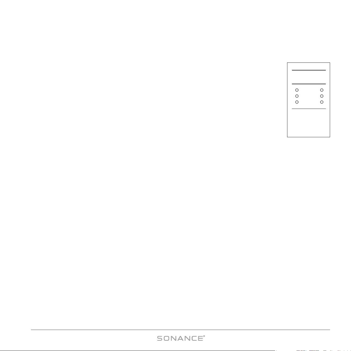
Protection Circuits
Thermal Protection
If the amplifier’s cooling vents are blocked, or it is installed with inadequate ventilation the amplifier may
exceed its safe operating temperature. If the amplifier’s internal temperature exceeds 154°F (68°C) it
will self-protect, and the following will occur:
• The audio output to all connected zones will shut OFF.
• The front-panel P
ROTECTION LEDs (see
Figure 3
) will illuminate
yellow
.
• An over-temp message will be sent via RS-232.
Once a safe temperature (<67°C) is reached, the Protection LEDs will all extinguish. You can then
re-activate the amplifier, either by switching the front-panel Power button OFF and ON or by a ‘Power’
command if the amplifier is being serial controlled.
IIMMPPOORRTTAANNTT:: BBeeffoorree rree-aaccttiivvaattiinngg tthhee aammpplliiffiieerr,, ccoorrrreecctt tthhee pprroobblleemm tthhaatt ccaauusseedd tthhee
oovveerr-tteemmppeerraattuurree ccoonnddiittiioonn ((vvoolluummee sseett ttoooo hhiigghh,, iinnaaddeeqquuaattee vveennttiillaattiioonn,, eettcc..))
NOTE: If you’re serial-controlling the 875D SE you can poll the amplifier at any time and its internal
temperature will be reported to the control device.
Over-Current Protection
If an over-current condition occurs in a zone, that zone will shut OFF for 5 seconds and its PROTECTION LEDs will flash ON
and OFF. The zone will then turn back ON. If the over-current condition continues the zone will shut OFF for 6 seconds,
its P
ROTECTION LEDs will flash, then it will turn back ON. If the over-current condition continues this process will repeat,
with the wait time increasing by 1 second each time. When the wait time reaches 10 seconds the zone will LOCK, the
zone’s P
ROTECTION LEDs will continually illuminate and the amplifier must be powered OFF using the front-panel POWER
button (or a serial command, if the amp is being controlled via RS-232).
BB ee ff oorr ee ttuurrnn ii nngg tthh ee aa mm ppllii ffii ee rr OO NN aa gg aa ii nn,,
cc oorrrr ee cctt ww hhaa tteevv ee rr iiss cc aauu ss iinngg tthh ee oovv ee rr-- ccuu rrrr ee nntt cc oonn ddii tt iioo nn ii nn t
thh ee zz oonn ee ((ssppeeaa kk ee rr ii mmpp ee ddaann ccee ttoo oo lloo ww,, vvooll uummee ttoo oo
hh iigg hh,, ss hhoo rrtt -- cciirr ccuu iitt,, ee tt cc..))..
PROTECTION
BBE ON
ACTIVE
Figure 3:
F
RONT-PANEL
STATUS LEDs
Page 8
8
SONAMP®875D SE 8-CHANNEL AMPLIFIER
Powering the Amplifier
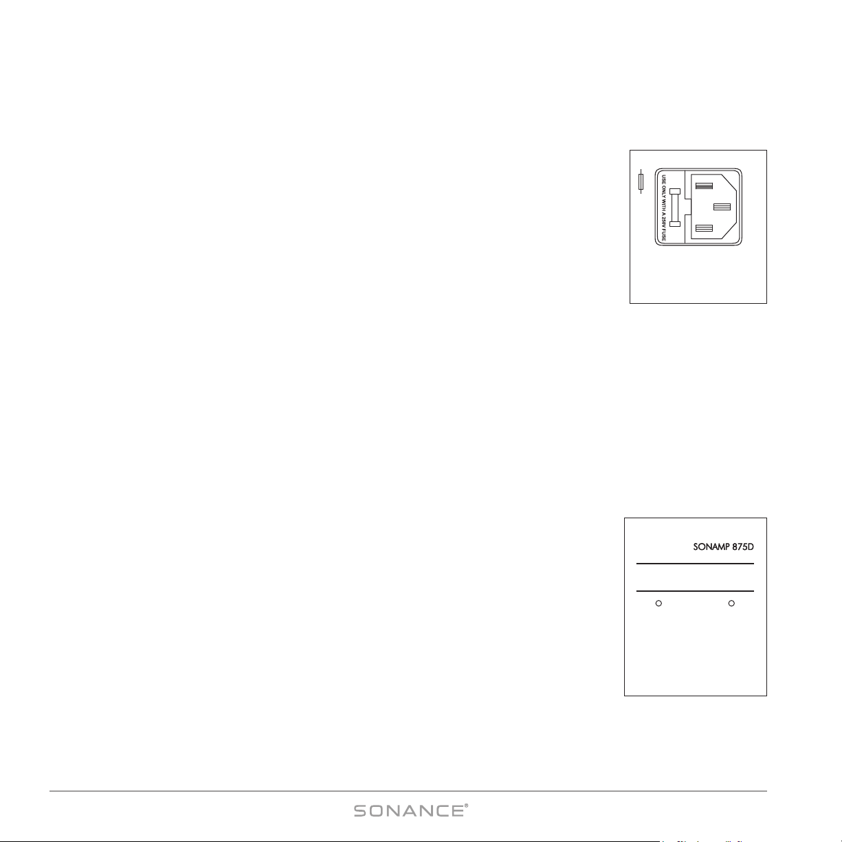
Power Cord (see Figure 4)
The Sonamp 875D SE features a removable IEC power cord. Plug the female end of the power
cord into the Power Cord Connector on the amplifier’s rear panel and plug the male end into a
20-amp grounded wall socket. DO NOT plug the power cord into an AC outlet on your
preamplifier/receiver.
CCAAUUTTIIOONN :: TToo pprreevveenntt eelleeccttrriicc sshhoocckk,, ddoo nnoott ddeeffeeaatt tthhee ggrroouunndd pprroonngg ooff tthhee
ppo
owweerr ccoorrdd pplluugg..
NOTE: If you need to use an extension cord, use only a heavy-duty (14-gauge or
larger) extension cord to avoid starving the amplifier of all the current
necessary for full-power operation.
Replacing the Fuse
(see Figure 4)
CCAAUUTTIIOONN:: FFoorr ccoonnttiinnuueedd pprrootteeccttiioonn aaggaaiinnsstt ffiirree,, rreeppllaaccee tthhee ffuussee wwiitthh oonnllyy tthhee
ssaammee ttyyppee aanndd rraattiinngg..
1. Remove the power cord from the wall outlet and from the amplifier’s Power Cord Connector.
2. Insert a flat-blade screwdriver or similar tool into the empty Power Cord Connector socket and gently pry the fuse holder out
of its socket.
3. Install the proper fuse in the fuse holder and replace the fuse holder back into its socket next to the power cord connection.
When the amplifier is operating, the fuse will blow to protect it from possible internal parts failure. NEVER replace the fuse
with any size other than that indicated on the rear panel to avoid more serious damage and the risk of fire. Substitution
of a larger fuse may create serious damage to internal parts and will void your Sonance warranty.
A.C. ON LED (see Figure 5)
The AC ON LED indicates that the amplifier’s power cord is plugged-into a live AC outlet and
its P
OWER button is ON. If the amplifier’s AC fuse ever opens, this LED will go out. To use the
A
UTO-ON feature (see page 12), this LED must remain ON at all times.
ACTIVE LED (see Figure 5)
The amplifier’s ACTIVE LED will illuminate whenever any zone is active. Each zone’s STATUS
INDICATORS (see
Figure 3
) also contain an ACTIVE LED that will illuminate whenever that particular
zone is ON.
A.C. ONACTIVE
Figure 5:
AC O
N and
A
CTIVE LEDs
CAUTION: REPLACE WITH THE
SAME TYPE AND RATING FUSE
120V–60Hz 1200W
–FUSE T10AL 250V
Figure 4:
Power Connector
and Fuse Holder
Page 9
9
SONAMP®875D SE 8-CHANNEL AMPLIFIER
Source Connections (see
Figures 6 & 7
)
Always use quality high-fidelity interconnect cables such as Sonance MediaLinQ®Bronze
Interconnects. If source components are more than 20 feet from the amplifier, use the Sonance LS2
and LR2 Balanced Line-Level Sender and Receiver (sold separately) to avoid signal degradation.
NOTE: Always check local building codes before installing wire in walls or ceilings.
• Connect stereo source components (receiver, preamp, page signal, etc.) that will feed all 8
channels to the B
US
LEFT & RIGHT inputs (see
Figure 6
).
• Connect a mono auxiliary source (page signal, electronic doorbell, etc.) that will feed all 8
channels to the B
US
AUX input (see
Figure 6
).
• Connect zone-specific sources (audio control system zone output, video game, etc.) into the
individual channel D
IRECT inputs (see
Figure 7
).
• Connect additional amplifiers to the buffered
Bus Outputs
(see
Figure 6
). The source connect-
ed to the B
US LEFT & RIGHT Inputs appears at the L and R OUTPUTS, and the source connected
to the B
US AUX input appears at the AUX OUTPUT.
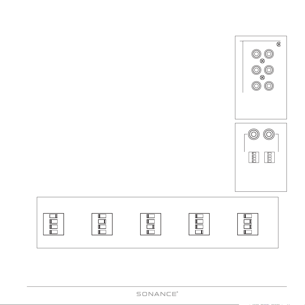
Input Assignment DIP Switches (see Figure 8)
The Sonamp 875D SE’s Input Assignment DIP switches provide the most flexible configuration
options of any multichannel amplifier. Settings are changed by setting the switches either OFF
(left) or ON (right):
DIRECT: Assign channel to the channel D
IRECT
input source.
LEFT: Assign channel to the Bus L
EFT input source (default for odd-numbered channels)
RIGHT: Assign channel to the Bus R
IGHT input source (default for even-numbered channels)
AUX: Assign channel to the Bus Aux input source
NOTE: All inputs selected by the DIP switches are summed-together. For example, for mono (L+R)
operation, activate both the Bus L and Bus R switches. Take care when setting volume levels, since
summed L&R inputs can increase signal gain by up to +6dB.
See pages 18 – 23 for illustrations of different system configurations.
ON
ON
ON
ON
OFF
OFF
OFF
OFF
ON
ON
ON
ON
OFF
OFF
OFF
OFF
DIRECT
LEFT
RIGHT
AUX
DIRECT
LEFT
RIGHT
AUX
CH1 CH2
(BRIDGED)
Figure 7:
Direct Inputs and
Input Assignment
DIP Switches
L
R
A
BUS
INPUT
OUTPUT
BUFFERED
Figure 6:
BUS Inputs &
Outputs; AUX Input
& Output
ON
ON
ON
ON
OFF
OFF
OFF
OFF
DIRECT
LEFT
RIGHT
AUX
ON
ON
ON
ON
OFF
OFF
OFF
OFF
DIRECT
LEFT
RIGHT
AUX
ON
ON
ON
ON
OFF
OFF
OFF
OFF
DIRECT
LEFT
RIGHT
AUX
ON
ON
ON
ON
OFF
OFF
OFF
OFF
DIRECT
LEFT
RIGHT
AUX
ON
ON
ON
ON
OFF
OFF
OFF
OFF
DIRECT
LEFT
RIGHT
AUX
DIRECT
INPUT
LEFT BUS
INPUT
RIGHT BUS
INPUT
AUX BUS
INPUT
MONO
OPERATION
Figure 8: Input Assignment DIP Switch Settings
Page 10

10
SONAMP®875D SE 8-CHANNEL AMPLIFIER
Input Sensitivity Adjustment
There are two ways to adjust the individual channel input sensitivity (volume) on the 875D SE:
• The front panel has recessed adjustment potentiometers (see
Figure 9
). These can be adjusted
using a small screwdriver.
• Input sensitivity can also be adjusted by serial command via the amplifier’s RS-232 connection
(see page 14).
NOTE: When the 875D SE is being serial-controlled, serial V
OLUME
commands
will override the front-panel input sensitivity settings. However, if the frontpanel controls are manually adjusted after the serial V
OLUME
commands are
sent, they will override the volume set by the serial commands.
Speaker Connections
IIMMPPOORRTTAANNTT :: AAllwwaayyss uunnpplluugg tthhee aammpplliiffiieerr’’ss ppoowweerr ccoorrdd ffrroomm tthhee wwaallll oouuttlleett bbeeffoorree mmaakkiinngg ssoouurrccee
ssiiggnnaall oorr ssppeeaakkeerr ccoonnnneeccttiioonnss..
Use Good Speaker Wire
For the best sound you should never use thin-gauge speaker wire – it will constrict the sound and diminish bass response.
We recommend that you use premium Sonance MediaLinQ speaker cable, which also complies with UL fire rating codes.
You may also experiment with audiophile brands of speaker cable and interconnects, but be sure to check local codes
governing wire that may be installed within walls or ceilings. Different brands of wire can have different characteristic
sounds and some may be more compatible with the sonic “signature” of your various audio system components.
Your Sonamp 875D SE is stable with any reputable brand of speaker wire or cable.
Speaker Connections for Stereo Operation (see Figure 10)
1. Run speaker wire from each speaker to the amplifier location. We recommend that you
mark each wire’s positive (‘+’) and negative (‘–’) leads, its channel (left or right) and which
zone it is from so that you can connect it to the proper speaker terminals.
2. Strip no more than ¼” of insulation from each speaker lead. Twist the strands or tin the
exposed wire with solder to ensure that there are no stray strands. (Stray strands that touch
each other or touch the amplifier chassis can cause a short-circuit that can damage the
amplifier.)
3. The Sonamp 875D SE has removable 4-wire speaker connectors (one for each zone) that
can accept wire up to 14AWG. Flip the four levers up to open the connector terminals.
4. Insert the exposed portions of the speaker wires into the terminal openings. Make sure to
insert the ‘+’ and ‘–’ leads into the correct openings, as indicated in the chassis markings
below
the connector.
5. After making sure that there are no stray wires touching each other, flip the four levers
down to lock the wires in the terminals.
+ 1 – – 2 +
BRIDGED
8Ω MIN
++
––
Flip all 4 Levers UP
Figure 10:
Stereo Speaker
Connections
LRLR
3 – 4 5 – 6
Figure 9:
Input Sensitivity
Adjustments
(Ch 3– 6 shown)
Page 11

11
SONAMP®875D SE 8-CHANNEL AMPLIFIER
6. Press the removable connector into the corresponding zone speaker connector on the amplifier until it locks into place.
• The removable connectors will only fit one way on the amplifier.
CCAAUUTTIIOONN :: AAllwwaayyss pprroovviiddee ssuuffffiicciieenntt ssllaacckk iinn wwiirreess ttoo aavvooiidd tteennssiioonn.. AAllwwaayyss ccoonnttaaiinn aannyy eexxcceessss wwiirree
ttoo pprreevveenntt ttrriippppiinngg hhaazzaarrddss..
Speaker Connections for Bridged Operation (see Figures 11 & 12)
The 875D SE can operate with any pair of channels (zone) in the single-channel bridged mode, which delivers 300 watts
RMS into an 8-ohm speaker.
BB ee ssuu rree tt hhee ss pp ee aakkeerr ii ss rr aatt ee dd ttoo hh aann dd llee tthh ii ss ii nncc rreeaa ss ee dd oo uuttppuutt pp ooww ee rr..
IIMMPPOORRTTAANNTT:: TThhee mmiinniimmuumm ssppeeaakkeerr iimmppeeddaannccee ffoorr BBrriiddggeedd OOppeerraattiioonn iiss 88 oohhmmss.. DDoo
nnoott ooppeerraattee aa
zzoonnee iinn tthhee BBrriiddggeedd mmooddee iinnttoo aa ssppeeaakkeerr tthhaatt iiss lleessss tthhaann
88 oohhmmss nnoommiinnaall iimmppeeddaannccee..
1. Move the N
ORMAL/BRIDGED switch for the zone to the BRIDGED
position (see
Figure 11
).
2. Strip no more than ¼” of insulation from the speaker leads.
Twist the strands or tin the exposed wire with solder to
ensure that there are no stray strands. (Stray strands that
touch each other or touch the amplifier chassis can cause a
short-circuit that can damage the amplifier.)
3. The Sonamp 875D SE has a removable 4-wire speaker connector for each zone that can accept wire up to 14AWG.
Flip the outer two levers up to open the connector terminals.
4. Insert the single speaker’s “+” and “–” speaker leads into
the two outer terminal openings on the 4-wire speaker
connector. Observe the polarity shown in the chassis
markings
above
the connector (see
Figure 12
).
5. After making sure that there are no stray wires touching
each other, flip the two levers down to lock the wires in the
terminal.
6. Press the removable connector into the corresponding zone speaker connector on the amplifier until it locks into place.
• The removable connectors will only fit one way on the amplifier.
NOTE: When a zone is bridged, the source connected to the odd-numbered input channel and the
I
NPUTASSIGNMENT
DIP switches for the odd-numbered channel function. The input connected to the
even-numbered channel and the switches for the even-numbered channel are disabled.
+ 1 – – 2 +
BRIDGED
8Ω MIN
+
–
Flip Outer 2 Levers UP
Figure 12:
Bridged Speaker
Connection
ON
ON
ON
ON
OFF
OFF
OFF
OFF
ON
ON
ON
ON
OFF
OFF
OFF
OFF
DIRECT
LEFT
RIGHT
AUX
DIRECT
LEFT
RIGHT
AUX
1 – – 2 + + 3
–
CH1 CH2
BRIDGED
8Ω MIN
B
8
NORMAL BRIDGED
BRIDGED
Figure 11:
Zone Bridging
Switch
Page 12

12
SONAMP®875D SE 8-CHANNEL AMPLIFIER
Auto-On
You can set your 875D SE so that any zone will automatically turn ON when it receives an
audio signal, or when it receives a control voltage from an external source (such as a
Sonance Navigator Harbor multi-zone controller). Each zone has two Trigger Mode switches
located on the rear panel: Auto — zone is turned ON when an audio signal is present, and
Volt — zone is turned ON by an external control voltage (see
Figure 14
).
NOTE: Setting both switches ON puts that zone in the Serial control mode,
disabling the Auto On feature. (See Serial Control, on page 14.)
AUTO (Audio) Trigger Mode
When a zone’s AUTO switch is set to the ON position, any audio signal arriving at the zone’s active
input connectors (as determined by the I
NPUT ASSIGNMENT DIP SWITCHES, see page 8) will activate
the zone for operation. The sensitivity of the zone’s A
UTO-ON circuit can be increased or decreased
by adjusting the A
UTO ON level control on the front panel (see
Figure 15
).
• Turning the control clockwise
increases
the sensitivity (
less
voltage is required to trigger the
A
UTO-ON function).
• Turning the control counter-clockwise
decreases
the sensitivity (
more
voltage is required to
trigger the A
UTO-ON function).
The A
UTO-ON trigger sensitivity ranges from 5mV/ch in the full clockwise position to OFF (AUTO-
O
N will not trigger) in the full counter-clockwise position.
In the A
UTO-O
N mode the zone will remain ON for approximately 3 minutes after the audio signal has ceased. This
provides ample time to prevent erratic operation from pauses between musical passages or while changing sources.
VOLTAGE Trigger Mode
When a zone’s VOLT switch is set to the ON position it can be automatically turned ON
by an external trigger voltage that appears at the zone’s E
XTERNAL TRIGGER INPUT
connections (see
Figure 16
).
• The trigger voltage must be between 5V and 24V, either AC or DC.
The 875D SE has individual E
XTERNAL TRIGGER INPUT connections for each zone, and an
additional E
XTERNAL TRIGGER INPUT connection (labeled ALL) that will turn all 4 zones ON
from a single voltage trigger.
The E
XTERNAL TRIGGER connectors feature flip-up levers similar to the ones used on the speaker connectors:
1. Open the levers for the zone’s E
XTERNAL TRIGGER inputs.
2. Insert the control wires into the appropriate openings in the connector.
3. Close the levers.
EXTERNAL TRIGGER
INPUTS 5 – 24V AC–DC
ALL CH1/2 3/4 5/6 7/8
CH
C
H
+ – + – + – + – + –
Figure 16:
External Trigger Input
Connections
AUTO
VOLT
AUTO
VOLT
AUTO
VOLT
AUTO
VOLT
TRIGGER MODE
CH 1/2
CH 3/4
CH 5/6
CH 7/8
OFF ON
RS-232
RS-232
RS-232
RS-232
Figure 14:
Auto-On Trigger Switches
AUTO ON
LRLR
3 – 4 5 – 6
Figure 15:
Zone A
UTO ON (Audio)
Trigger Sensitivity
Adjustments
Page 13

13
SONAMP®875D SE 8-CHANNEL AMPLIFIER
OFF (Bypass) Mode
When a zone’s A
UTO and VOLT Auto-On Trigger switches are both set in the OFF position, the A
UTO-ON circuitry is
bypassed and the amplifier’s front-panel P
OWER button will turn all zones ON and OFF simultaneously (see
Figure 2
, on
page 5).
BBE®Sound Enhancement
The Sonamp 875D SE incorporates BBE®Sound Enhancement. The BBE process improves
the presence and detail of speakers, especially at lower listening volumes, improving the
sound quality of your music — especially distributed audio systems playing background
music. BBE also restores clarity and definition (or focus) to spoken voices, which makes
paging systems easier to understand without having to run them at high volumes. Each
zone in the 875D SE has 2 individual switches that let you set the BBE enhancement for
that zone to HIGH (+9dB), LOW (+6dB) or OFF (see
Figure 17
):
• If the OFF/ON switch is set to OFF, BBE enhancement is not applied
• If the OFF/ON switch is set to ON, BBE enhancement is applied according to the set-
ting of the LOW/HIGH switch: LOW = +6dB of BBE enhancement; HIGH = +9dB of
BBE enhancement.
NOTE: The factory-default setting is +6dB on all zones.
The 875D SE also has a set of BBE CONTROL INPUT connections that allow the BBE
enhancement for each zone to be triggered ON and OFF individually by an external
control voltage (see
Figure 17
):
• The BBE OFF/ON switch for the zone must be in the OFF position.
• The trigger voltage must be between 5V and 24V, either AC or DC.
The E
XTERNAL TRIGGER connectors feature flip-up levers similar to the ones used on the speaker connectors:
1. Open the levers for the zone’s E
XTERNAL TRIGGER inputs.
2. Insert the control wires into the appropriate openings in the connector.
3. Close the levers.
The front-panel Z
ONE STATUS LEDs indicate if BBE processing is being applied to a zone (see
Figure 3
, on page 7).
BBE CONTROL
BBE CONTROL
INPUTS 5 – 24V AC–DC
OFF
LOW
OFF
LOW
OFF
LOW
OFF
LOW
ON
HIGHONHIGHONHIGHONHIGH
1/2 3/4 5/6 7/8 CH
+ – + – + – + –
Figure 17:
BBE Control Switches and
External Control Input
Connections
Page 14

14
SONAMP®875D SE 8-CHANNEL AMPLIFIER
Zone Trigger Outputs
The 875D SE has individual TRIGGER OUTPUT connections for each zone that provide 12V
DC whenever the zone is ON (see
Figure 18
). This trigger can be used to control other
devices such as Sonance AL2/AS2 automatic secondary switches, other Sonamps or
12V relays.
• The current draw on each zone’s T
RIGGER OUTPUT connection should not exceed
200mA.
The T
RIGGER OUTPUT connectors feature flip-up levers similar to the ones used on the
speaker connectors:
1. Open the levers for the zone’s T
RIGGER OUTPUTS.
2. Insert the control wires into the appropriate openings in the connector (observe the correct “+” and “–” polarity).
3. Close the levers.
Serial Control
The 875D SE’s RS-232 Control Input (see
Figure 19
) allows many 875D SE functions to be
serial-controlled by 3rd-party control systems, and allows many of the amplifier’s performance
parameters to be monitored in real-time via the 3rd-party controller.
The 875D SE’s open architecture allows you to use it with a variety of RS-232 controllers. Specific
modules for use with Crestron
®
and AMX®controllers are available for download at
ww wwww..ssoo nnaann ccee..cc oomm
. Please check the website for information about compatibility with additional
controllers.
Connecting the 875D SE to a Serial Control Device
The 875D SE’s RS-232 Pinout is:
PPii nn 22 :: RR XX DD ;; PPii nn 33 :: TT XX DD ;; PPii nn 55 :: GG NN DD..
Use a null modem cable to connect the 875D SE’s RS-232 C
ONTROL INPUT to a serial control device. To verify the pinout of
other serial devices, the TXD pin of an active port will show a negative DC voltage.
NOTE: To connect to a Crestron controller, use the Crestron CNSP-124
cable (available separately from Crestron).
Enabling 875D SE Zone Serial Control
To enable serial control of of a zone, both of that zone’s AUTO and VOLT Trigger Mode
switches must be set in the ON position (see
Figure 20
). Setting a zone to
RS-232
disables
its rear-panel Auto and Voltage trigger functions — they can only be serial-controlled.
NOTE: Zones not set for RS-232 control can be polled by the control
device, but cannot be controlled by the device.
EXTERNAL TRIGGER
INPUTS 5 – 24V AC
–
ALL CH1/2 3/4 5/6 7/8
+ – + – + – + – + –
Figure 18: Zone Trigger Output
Connections
RS-232
Figure 19:
RS-232 Control Input
AUTO
VOLT
AUTO
VOLT
AUTO
VOLT
AUTO
VOLT
TRIGGER MODE
CH 1/2
CH 3/4
CH 5/6
CH 7/8
OFF ON
RS-232
RS-232
RS-232
RS-232
Figure 20:
All Four Zones set for
Serial Control
Page 15

15
SONAMP®875D SE 8-CHANNEL AMPLIFIER
875D SE Serial Commands
Serial Protocol: Baud Rate = 9600, N, 8, 1; single CR
CCoo mm mm aann dd ss IInn SS yy nntt aa xx PPaarr aa mm ee tt ee rr ss SS ttaattee
Power :Pxy<cr> x = Zone 1-4 or G (Global), y = State 0= Off; 1= On
Zone Volume Set :Vxyyy<cr> x = Zone 1-4 or G (Global), yyy = Volume 0 - 100 0 (Off) – 100 (Max)
Channel Volume Set :VCxyyy<cr> x = Channel 1 - 8 or G (Global), yyy = Volume 0 - 100 0 (Off) – 100 (Max)
NOTE: Issuing a Volume Set command when the amplifier is OFF will pre-set the zone or channel’s start-up
volume to that level.
Zone Volume Incremental Step :Vxyy<cr> x = Zone 1-4 or G (Global), yy = Volume Step Down/Up -n = Down, +n = Up; n = 1 to 5
Channel Volume Incremental Step: :VCxyy<cr> x = Channel 1-8 or G (Global), yy = Volume Step Down/Up -n = Down, +n + up; n = 1 to 5
NOTE: The 875D SE stores independent settings for Channel and Zone Volume. If Channel Volume
commands are sent to a zone that is being controlled with Zone Volume commands (and visa-versa),
the volume may initially change to a different level than expected.
Zone Mute :Mxy<cr> x = Zone 1-4 or G (Global), y = State 0 = Mute Off; 1= Mute On
Channel Mute :MCxy<cr> x = Channel 1 - 8 or G (Global), y = State 0 = Mute Off; 1 = Mute On
BBE Signal Processing :BPxy<cr> x = Zone 1-4 or G (Global), y = State 0= Off; 1= On
BBE HI & LO Frequency Boost :BBxy<cr> x = Zone 1-4 or G (Global), y = State 0= +6dB; 1=+9dB
NOTE: The echo for this will provide two values (HI and LO)
BBE HI Frequency Boost :BHxy<cr> x = Zone 1-4 or G (Global), y = State 0= +6dB; 1=+9dB
BBE LO Frequency Boost :BLxy<cr> x = Zone 1-4 or G (Global), y = State 0= +6dB; 1=+9dB
Adding a question-mark character before the carriage return of any of the above commands will turn the command into a
query. Additionally, the following unique queries can also be issued:
QQ uueerr iieess SS yy nntt aa xx PPaarr aa mm ee tt ee rr ss SS ttaattee
Temperature :TP?<cr> – 0 – 100 Degrees C
Audio Trigger Input :ATIx?<cr> x = Zone 1-4 or G (Global) [see
Notes
] 0= Off; 1= On
Fault/Protection :FPx?<cr> x = Zone 1-4 or G (Global) [see
Notes
] 0= Normal; 1= Fault
Voltage Trigger Input :VTIx?<cr> x = Zone 1-4, A (All) or G (Global) [see
Notes
] 0= Off; 1= On
Front-Panel Input Control Level :TVLx?<cr> x = Channel 1-8 or G (Global) [see
Notes
] 0 – 100
Firmware Version :VER?<cr> – Version 1.03 or later
(continued on page 16)
Page 16

16
SONAMP®875D SE 8-CHANNEL AMPLIFIER
Serial Control Notes:
1. The 875D SE will respond to each command with the new value after the command is acted-upon.
EE xx aa mmppllee::
Zone 2 volume is 53. If a “:V2+3” (increase Zone 2 volume +3 steps) command is then issued, the 875D SE
echoes back (V256) (Zone 2 volume is 56).
2. The 875D SE will respond to invalid commands with “ERR”.
EE xx aa mmppllee::
A “:V7?” poll is received (What is Zone 7 volume?). Since there is no Zone 7, the 875D SE echoes back “ERR”.
3. The 875D SE will respond with “N/A” if a recognized command cannot be executed.
EE xx aa mmppllee::
Zone 4 is OFF when a “:V4?” (What is Zone 4 volume?) query is received. Since Zone 4 is OFF, the 875D SE
echoes back “N/A”.
4a. Any command followed by a “?” will be treated as a Query and will cause the 875D SE to echo back the current state
for that zone (z) or channel (c).
EE xx aa mmppllee::
Zone 4 is OFF and a “:P4?” query is received. The 875D SE echoes back “P40” (Zone 4 power is OFF).
4b. A command followed by a “G?” will be treated as a Global query and will cause the 875D SE to echo back the
current state of each zone or channel.
EE xx aa mmppllee::
A “:BPG?” (Is BBE ON or OFF in Zones 1 – 4?) query is received. The 875D SE echoes back:
BP11 (Zone 1 BBE is ON); BP21 (Zone 2 BBE is ON); BP30 (Zone 3 BBE is OFF); BP40 (Zone 4 BBE is OFF)
5. When an over-temperature or fault condition occurs, activating the amplifier’s protection circuits, the 875D SE will issue
an unsolicited echo reporting that condition.
EE xx aa mmppllee 11 ::
If the temperature inside the amplifier reaches 68°C, it will issue the unsolicited echo “TP68”.
EE xx aa mmppllee 22 ::
If Zone 1 experiences a fault the amplifier will issue the unsolicited echo “FP1”.
6. When the amplifier is plugged-in it will automatically issue its AMX beacon.
Page 17

17
SONAMP®875D SE 8-CHANNEL AMPLIFIER
Specifications
Number of Channels: 8 (four stereo pairs)
Output Power (Stereo): 75 watts RMS per channel (X8), 0.25% THD, 20Hz – 20kHz, @ 8 ohms;
140 Watts per channel (X8), 0.1% THD, 1kHz, @ 4 ohms
Output Power (Bridged): 300 Watts per channel (X4) @ 8 ohms
Frequency Response: 20Hz – 20kHz, ±1dB
Total Harmonic Distortion: 0.05% (1kHz, 8 ohms); 0.10% (1kHz, 4 ohms)
Signal to Noise Ratio: -96dB (w/22kHz filter)
Input Sensitivity: 1.5V for 75W RMS Output
1.3V w/BBE ON (+6dB)
1.0V w/BBE ON (+9dB)
Input Impedance: 10k ohms
Maximum Source Input Voltage: 4.0 VAC RMS
3.0V AC RMS w/BBE ON
Loop Output Impedance (Buffered): 100 ohms
Serial Protocol (RS-232 Connection): 9600, N, 8, 1, single CR
Power Consumption: 1,200 Watts
BTU/HR: 850
AC Fuse: 10A (T10AL ~ 250V)
Dimensions (WxHxD): 16½” x 3
7
/
8
” x 17¼” (419mm x 98mm x 438mm)
Dimensions (w/Rack Ears, WxHxD): 19” x 2½” x 17¼” (483mm x 64mm x 438mm)
Shipping Weight: 47 lbs (21.4kg)
Installation Examples
The illustrations on the following pages show the wide variety of audio and audio/video systems that can be assembled
using one or more Sonamp 875D SE amplifiers. Your local authorized Sonance dealer is an expert in audio/video system
planning and installation. Sonance strongly recommends that you work with your dealer to ensure that your system is
properly planned, assembled and installed.
Page 18

18
SONAMP®875D SE 8-CHANNEL AMPLIFIER
System 1: Basic Background Music System with Paging Capabilities
FFeeaa ttuurreess:: CCoo mm mm oonn MM uu ssiicc SS oouu rrcc ee ff oo rr aallll FF oouurr RRoo oo mmss •• TTww oo ZZoonneess wwiitthh PPaa gg ii nngg CC aappaabb iillii tt ii ee ss
Connecting a telephone page output (residential) or microphone preamp output (commercial) to the 875D SE’s Aux Bus
input and a music source to the L
EFT
& RIGHT BUS inputs lets you mix a music source with a paging signal. The INPUT
ASSIGNMENT DIP SWITCHES let you individually configure each channel to receive or not receive the paging (Aux) input. If
you wish to mute the music during paging you can route the amplifier’s L/R input connections through a Sonance AL2/S
Secondary Source Selector activated by a 12V DC control signal from the paging device.
ON
ON
ON
ON
OFF
OFF
OFF
OFF
ON
ON
ON
ON
OFF
OFF
OFF
OFF
ON
ON
ON
ON
OFF
OFF
OFF
OFF
ON
ON
ON
ON
OFF
OFF
OFF
OFF
ON
ON
ON
ON
OFF
OFF
OFF
OFF
ON
ON
ON
ON
OFF
OFF
OFF
OFF
ON
ON
ON
ON
OFF
OFF
OFF
OFF
ON
ON
ON
ON
OFF
OFF
OFF
OFF
L
R
A
BBE CONTROL
BUS
INPUT
OUTPUT
BUFFERED
DIRECT
LEFT
RIGHT
AUX
DIRECT
LEFT
RIGHT
AUX
DIRECT
LEFT
RIGHT
AUX
DIRECT
LEFT
RIGHT
AUX
DIRECT
LEFT
RIGHT
AUX
DIRECT
LEFT
RIGHT
AUX
DIRECT
LEFT
RIGHT
AUX
DIRECT
LEFT
RIGHT
AUX
BBE CONTROL
INPUTS 5 – 24V AC–DC
EXTERNAL TRIGGER
INPUTS 5 – 24V AC–DC
TRIGGER OUTPUTS
12VDC
OFF
LOW
OFF
LOW
OFF
LOW
OFF
LOW
ON
HIGHONHIGHONHIGHONHIGH
1/2 3/4 5/6 7/8
+ 1 – – 2 + + 3 – – 4 + + 5 – – 6 + + 7 – – 8 +
CH
CH1 CH2
NORMAL BRIDGED NORMAL BRIDGED
ALL CH
CH
RS-232
1/2 3/4 5/6 7/8
ALL
S/N
1/2 3/4 5/6 7/8
+ – + – + – + – + –
BRIDGED
8Ω MIN
BRIDGED
8Ω MIN
BRIDGED
8Ω MIN
BRIDGED
8Ω MIN
NORMAL BRIDGED NORMAL BRIDGED
+ – + – + – + –
(BRIDGED)
CH3 CH4
(BRIDGED)
CH5 CH6
(BRIDGED)
CH7 CH8
(BRIDGED)
CAUTION: REPLACE WITH THE
SAME TYPE AND RATING FUSE
SONAMP® 875D SE
120V–60Hz 1200W
–FUSE T10AL 250V
AUTO
VOLT
AUTO
VOLT
AUTO
VOLT
AUTO
VOLT
TRIGGER MODE
CH 1/2
CH 3/4
CH 5/6
CH 7/8
OFF ON
RS-232
RS-232
RS-232
RS-232
ON
ON
ON
ON
OFF
OFF
OFF
OFF
ON
ON
ON
ON
OFF
OFF
OFF
OFF
DIRECT
LEFT
RIGHT
AUX
DIRECT
LEFT
RIGHT
AUX
ON
ON
ON
ON
OFF
OFF
OFF
OFF
ON
ON
ON
ON
OFF
OFF
OFF
OFF
DIRECT
LEFT
RIGHT
AUX
DIRECT
LEFT
RIGHT
AUX
ON
ON
ON
ON
OFF
OFF
OFF
OFF
ON
ON
ON
ON
OFF
OFF
OFF
OFF
DIRECT
LEFT
RIGHT
AUX
DIRECT
LEFT
RIGHT
AUX
ON
ON
ON
ON
OFF
OFF
OFF
OFF
ON
ON
ON
ON
OFF
OFF
OFF
OFF
DIRECT
LEFT
RIGHT
AUX
DIRECT
LEFT
RIGHT
AUX
MICROPHONE PREAMP
— OR —
TELEPHONE PAGE OUT
INPUT SOURCE
TAPE RECORD
OUTPUT
OUTPUT
ZONE 1
Music + Paging
ZONE 4ZONE 2
Music Only Music Only Music + Paging
ZONE 3
CD iPORT TAPE SATELLITE
Volume Control Volume Control Volume Control Volume Control
FROM SOURCE
COMPONENTS
Channel Assignment
DIP Switch Settings
Channel Assignment
DIP Switch Settings
Channel Assignment
DIP Switch Settings
Channel Assignment
DIP Switch Settings
Set All Zones to ‘Auto’ ON
AUTO
VOLT
AUTO
VOLT
AUTO
VOLT
AUTO
VOLT
TRIGGER MODE
CH 1/2
CH 3/4
CH 5/6
CH 7/8
OFF ON
RS-232
RS-232
RS-232
RS-232
Page 19

19
SONAMP®875D SE 8-CHANNEL AMPLIFIER
System 2: 7.1-Channel Home Theater System
FFeeaa ttuurreess:: UUpp tt oo 11 4400WW oo uuttpp uutt pp ooww ee rr ppeerr cchh aa nn nneell (( 44 -- oo hh mm ss )) •• AAllll oo wwss uussee ooff ppaa ss ss iivv ee ii nn-- wwaa ll ll ssuu bbww oooo ffeerr
The 875D SE can power all eight channels of a 7.1-channel home theater system while occupying only 2U of rack space.
The surround sound processor’s preamp outputs feed each channel’s D
IRECT INPUT CONNECTION, and each channel’s I
NPUT
ASSIGNMENT DIP SWITCH is set to DIRECT. For larger home theaters, two 875D SEs can be used with all 16 channels operating
in the bridged mode, supplying 300 watts to each of the 8 speakers in the system.
ON
ON
ON
ON
OFF
OFF
OFF
OFF
ON
ON
ON
ON
OFF
OFF
OFF
OFF
ON
ON
ON
ON
OFF
OFF
OFF
OFF
ON
ON
ON
ON
OFF
OFF
OFF
OFF
ON
ON
ON
ON
OFF
OFF
OFF
OFF
ON
ON
ON
ON
OFF
OFF
OFF
OFF
ON
ON
ON
ON
OFF
OFF
OFF
OFF
ON
ON
ON
ON
OFF
OFF
OFF
OFF
L
R
A
BBE CONTROL
BUS
INPUT
OUTPUT
BUFFERED
DIRECT
LEFT
RIGHT
AUX
DIRECT
LEFT
RIGHT
AUX
DIRECT
LEFT
RIGHT
AUX
DIRECT
LEFT
RIGHT
AUX
DIRECT
LEFT
RIGHT
AUX
DIRECT
LEFT
RIGHT
AUX
DIRECT
LEFT
RIGHT
AUX
DIRECT
LEFT
RIGHT
AUX
BBE CONTROL
INPUTS 5 – 24V AC–DC
EXTERNAL TRIGGER
INPUTS 5 – 24V AC–DC
TRIGGER OUTPUTS
12VDC
OFF
LOW
OFF
LOW
OFF
LOW
OFF
LOW
ON
HIGHONHIGHONHIGHONHIGH
1/2 3/4 5/6 7/8
+ 1 – – 2 + + 3 – – 4 + + 5 – – 6 + + 7 – – 8 +
CH
CH1 CH2
NORMAL BRIDGED NORMAL BRIDGED
ALL CH
CH
RS-232
1/2 3/4 5/6 7/8
ALL
S/N
1/2 3/4 5/6 7/8
+ – + – + – + – + –
BRIDGED
8Ω MIN
BRIDGED
8Ω MIN
BRIDGED
8Ω MIN
BRIDGED
8Ω MIN
NORMAL BRIDGED NORMAL BRIDGED
+ – + – + – + –
(BRIDGED)
CH3 CH4
(BRIDGED)
CH5 CH6
(BRIDGED)
CH7 CH8
(BRIDGED)
CAUTION: REPLACE WITH THE
SAME TYPE AND RATING FUSE
SONAMP® 875D SE
120V–60Hz 1200W
–FUSE T10AL 250V
AUTO
VOLT
AUTO
VOLT
AUTO
VOLT
AUTO
VOLT
TRIGGER MODE
CH 1/2
CH 3/4
CH 5/6
CH 7/8
OFF ON
RS-232
RS-232
RS-232
RS-232
FRONT
LEFT
FRONT
RIGHT
SIDE
LEFT
SIDE
RIGHT
BACK
LEFT
BACK
RIGHT CENTER
SUB
WOOFER
7.1-CHANNEL
SURROUND SOUND
PROCESSOR
FRONT LEFT CENTER FRONT RIGHT
SIDE LEFT SIDE RIGHT
BACK LEFT BACK RIGHT
PASSIVE
SUBWOOFER
ON
ON
ON
ON
OFF
OFF
OFF
OFF
ON
ON
ON
ON
OFF
OFF
OFF
OFF
DIRECT
LEFT
RIGHT
AUX
DIRECT
LEFT
RIGHT
AUX
NORMAL BRIDGED
FOR ALL
CHANNELS:
Set All
Zones to
‘Auto’ ON
AUTO
VOLT
AUTO
VOLT
AUTO
VOLT
AUTO
VOLT
TRIGGER MODE
CH 1/2
CH 3/4
CH 5/6
CH 7/8
OFF ON
RS-232
RS-232
RS-232
RS-232
Page 20

20
SONAMP®875D SE 8-CHANNEL AMPLIFIER
ON
ON
ON
ON
OFF
OFF
OFF
OFF
ON
ON
ON
ON
OFF
OFF
OFF
OFF
ON
ON
ON
ON
OFF
OFF
OFF
OFF
ON
ON
ON
ON
OFF
OFF
OFF
OFF
ON
ON
ON
ON
OFF
OFF
OFF
OFF
ON
ON
ON
ON
OFF
OFF
OFF
OFF
ON
ON
ON
ON
OFF
OFF
OFF
OFF
ON
ON
ON
ON
OFF
OFF
OFF
OFF
L
R
A
BBE CONTROL
BUS
INPUT
OUTPUT
BUFFERED
DIRECT
LEFT
RIGHT
AUX
DIRECT
LEFT
RIGHT
AUX
DIRECT
LEFT
RIGHT
AUX
DIRECT
LEFT
RIGHT
AUX
DIRECT
LEFT
RIGHT
AUX
DIRECT
LEFT
RIGHT
AUX
DIRECT
LEFT
RIGHT
AUX
DIRECT
LEFT
RIGHT
AUX
BBE CONTROL
INPUTS 5 – 24V AC–DC
EXTERNAL TRIGGER
INPUTS 5 – 24V AC–DC
TRIGGER OUTPUTS
12VDC
OFF
LOW
OFF
LOW
OFF
LOW
OFF
LOW
ON
HIGHONHIGHONHIGHONHIGH
1/2 3/4 5/6 7/8
+ 1 – – 2 + + 3 – – 4 + + 5 – – 6 + + 7 – – 8 +
CH
CH1 CH2
NORMAL BRIDGED NORMAL BRIDGED
ALL CH
CH
RS-232
1/2 3/4 5/6 7/8
ALL
S/N
1/2 3/4 5/6 7/8
+ – + – + – + – + –
BRIDGED
8Ω MIN
BRIDGED
8Ω MIN
BRIDGED
8Ω MIN
BRIDGED
8Ω MIN
NORMAL BRIDGED NORMAL BRIDGED
+ – + – + – + –
(BRIDGED)
CH3 CH4
(BRIDGED)
CH5 CH6
(BRIDGED)
CH7 CH8
(BRIDGED)
CAUTION: REPLACE WITH THE
SAME TYPE AND RATING FUSE
SONAMP® 875D SE
120V–60Hz 1200W
–FUSE T10AL 250V
AUTO
VOLT
AUTO
VOLT
AUTO
VOLT
AUTO
VOLT
TRIGGER MODE
CH 1/2
CH 3/4
CH 5/6
CH 7/8
OFF ON
RS-232
RS-232
RS-232
RS-232
ZONE 1 ZONE 4ZONE 2 ZONE 3
K2
Keypad
K1
Keypad
K2
Keypad
K2
Keypad
F
U
S
E
F
U
S
E
F
U
S
E
F
U
S
E
6
54321
ON
ON
ON
ON
OFF
OFF
OFF
OFF
DIRECT
LEFT
RIGHT
AUX
NORMAL BRIDGED
FOR ALL
CHANNELS:
To Additional Zones
(Keypads/Amplifiers)
From A/V Sources
(CD player, DVD Player, VCR, iPort, etc.)
Sonance
Navigator Harbor
875D SE
875D SE Channel 1 – 8
External Trigger
Inputs
connected to Navigator
Harbor keypad
Status +
and
Status –
terminals. Set
875D SE
Trigger Mode
switches to
Volt
position.
System 3: Multi-Zone System with Controller
FFeeaa ttuurreess:: CChh aann nneellss aa uu tt oo mmaa tt iiccaa llll yy aacc tt ii vvaatt ee dd bb yy cc oonn tt rroo ll ll ee rr •• EE aacc hh zz oonn ee cc aa nn bbee ccoo nntt rroo ll ll ee dd bb yy ii nn-- zz oonn ee kk ee yy pp aadd
The 875D SE is ideal for use with a multi-zone controller like the Sonance Navigator
®
Harbor. By connecting the Navigator
Harbor’s Zone Keypad Status + and – terminals to the 875D SE’s External Control Input connections, the controller will
automatically turn the amplifier’s channels ON and OFF as they are needed.
Page 21

21
SONAMP®875D SE 8-CHANNEL AMPLIFIER
ON
ON
ON
ON
OFF
OFF
OFF
OFF
ON
ON
ON
ON
OFF
OFF
OFF
OFF
ON
ON
ON
ON
OFF
OFF
OFF
OFF
ON
ON
ON
ON
OFF
OFF
OFF
OFF
ON
ON
ON
ON
OFF
OFF
OFF
OFF
ON
ON
ON
ON
OFF
OFF
OFF
OFF
ON
ON
ON
ON
OFF
OFF
OFF
OFF
ON
ON
ON
ON
OFF
OFF
OFF
OFF
L
R
A
BBE CONTROL
BUS
INPUT
OUTPUT
BUFFERED
DIRECT
LEFT
RIGHT
AUX
DIRECT
LEFT
RIGHT
AUX
DIRECT
LEFT
RIGHT
AUX
DIRECT
LEFT
RIGHT
AUX
DIRECT
LEFT
RIGHT
AUX
DIRECT
LEFT
RIGHT
AUX
DIRECT
LEFT
RIGHT
AUX
DIRECT
LEFT
RIGHT
AUX
BBE CONTROL
INPUTS 5 – 24V AC–DC
EXTERNAL TRIGGER
INPUTS 5 – 24V AC–DC
TRIGGER OUTPUTS
12VDC
OFF
LOW
OFF
LOW
OFF
LOW
OFF
LOW
ON
HIGHONHIGHONHIGHONHIGH
1/2 3/4 5/6 7/8
+ 1 – – 2 + + 3 – – 4 + + 5 – – 6 + + 7 – – 8 +
CH
CH1 CH2
NORMAL BRIDGED NORMAL BRIDGED
ALL CH
CH
RS-232
1/2 3/4 5/6 7/8
ALL
S/N
1/2 3/4 5/6 7/8
+ – + – + – + – + –
BRIDGED
8Ω MIN
BRIDGED
8Ω MIN
BRIDGED
8Ω MIN
BRIDGED
8Ω MIN
NORMAL BRIDGED NORMAL BRIDGED
+ – + – + – + –
(BRIDGED)
CH3 CH4
(BRIDGED)
CH5 CH6
(BRIDGED)
CH7 CH8
(BRIDGED)
CAUTION: REPLACE WITH THE
SAME TYPE AND RATING FUSE
SONAMP® 875D SE
120V–60Hz 1200W
–FUSE T10AL 250V
ON
ON
ON
ON
OFF
OFF
OFF
OFF
ON
ON
ON
ON
OFF
OFF
OFF
OFF
ON
ON
ON
ON
OFF
OFF
OFF
OFF
ON
ON
ON
ON
OFF
OFF
OFF
OFF
ON
ON
ON
ON
OFF
OFF
OFF
OFF
ON
ON
ON
ON
OFF
OFF
OFF
OFF
ON
ON
ON
ON
OFF
OFF
OFF
OFF
ON
ON
ON
ON
OFF
OFF
OFF
OFF
L
R
A
BBE CONTROL
BUS
INPUT
OUTPUT
BUFFERED
DIRECT
LEFT
RIGHT
AUX
DIRECT
LEFT
RIGHT
AUX
DIRECT
LEFT
RIGHT
AUX
DIRECT
LEFT
RIGHT
AUX
DIRECT
LEFT
RIGHT
AUX
DIRECT
LEFT
RIGHT
AUX
DIRECT
LEFT
RIGHT
AUX
DIRECT
LEFT
RIGHT
AUX
BBE CONTROL
INPUTS 5 – 24V AC–DC
EXTERNAL TRIGGER
INPUTS 5 – 24V AC–DC
TRIGGER OUTPUTS
12VDC
OFF
LOW
OFF
LOW
OFF
LOW
OFF
LOW
ON
HIGHONHIGHONHIGHONHIGH
1/2 3/4 5/6 7/8
+ 1 – – 2 + + 3 – – 4 + + 5 – – 6 + + 7 – – 8 +
CH
CH1 CH2
NORMAL BRIDGED NORMAL BRIDGED
ALL CH
CH
RS-232
1/2 3/4 5/6 7/8
ALL
S/N
1/2 3/4 5/6 7/8
+ – + – + – + – + –
BRIDGED
8Ω MIN
BRIDGED
8Ω MIN
BRIDGED
8Ω MIN
BRIDGED
8Ω MIN
NORMAL BRIDGED NORMAL BRIDGED
+ – + – + – + –
(BRIDGED)
CH3 CH4
(BRIDGED)
CH5 CH6
(BRIDGED)
CH7 CH8
(BRIDGED)
CAUTION: REPLACE WITH THE
SAME TYPE AND RATING FUSE
SONAMP® 875D SE
120V–60Hz 1200W
–FUSE T10AL 250V
AUTO
VOLT
AUTO
VOLT
AUTO
VOLT
AUTO
VOLT
TRIGGER MODE
CH 1/2
CH 3/4
CH 5/6
CH 7/8
OFF ON
RS-232
RS-232
RS-232
RS-232
AUTO
VOLT
AUTO
VOLT
AUTO
VOLT
AUTO
VOLT
TRIGGER MODE
CH 1/2
CH 3/4
CH 5/6
CH 7/8
OFF ON
RS-232
RS-232
RS-232
RS-232
Audio Distribution
Processor
Controller Unit
TouchScreen Control Panel
L
R
AUDIO OUTPUTS
CONTROL INPUT
CONTROL OUTPUTS
TOUCH
SCREENS
ZONE1ZONE2ZONE3ZONE4ZONE5ZONE
6
L
R
SOURCE
INPUTS
123456
ZONE7ZONE
8
RS-232 RS-232
RS-232
RS-232
RS-232
From Source Components
To Internet
(For Remote Monitoring
of Amplifier)
To Zone 5 To Zone 6 To Zone 7 To Zone 8
To Zone 1 To Zone 2 To Zone 3 To Zone 4
ON
ON
ON
ON
OFF
OFF
OFF
OFF
DIRECT
LEFT
RIGHT
AUX
NORMAL BRIDGED
FOR ALL
CHANNELS:
Set ‘Auto’ and ‘Volt’ Switches
for All Zones to ON
Set ‘Auto’ and ‘Volt’ Switches
for All Zones to ON
System 4: Advanced Multi-Zone System with Central Control System
FFeeaa ttuurreess:: SSeerriiaall ccoo nntt rroo ll oo ff aa mmppll ii ff ii ee rr ss •• AA mm pp ll ii ff ii ee rr pp aarraa mm ee tt ee rr ss cc aann bb ee mmoo nnii tt oorr ee dd oo nn ccoo nntt rroo ll ll ee rr dd ii ss pp ll aayy
The 875D SE’s RS-232 connector allows it to be directly controlled by central whole-home control systems. The system
programmer can build the 875D SE’s functions into macros, and can display amplifier operating parameters on the
controller’s touchscreen displays.
Page 22

22
SONAMP®875D SE 8-CHANNEL AMPLIFIER
ON
ON
ON
ON
OFF
OFF
OFF
OFF
ON
ON
ON
ON
OFF
OFF
OFF
OFF
ON
ON
ON
ON
OFF
OFF
OFF
OFF
ON
ON
ON
ON
OFF
OFF
OFF
OFF
ON
ON
ON
ON
OFF
OFF
OFF
OFF
ON
ON
ON
ON
OFF
OFF
OFF
OFF
ON
ON
ON
ON
OFF
OFF
OFF
OFF
ON
ON
ON
ON
OFF
OFF
OFF
OFF
L
R
A
BBE CONTROL
BUS
INPUT
OUTPUT
BUFFERED
DIRECT
LEFT
RIGHT
AUX
DIRECT
LEFT
RIGHT
AUX
DIRECT
LEFT
RIGHT
AUX
DIRECT
LEFT
RIGHT
AUX
DIRECT
LEFT
RIGHT
AUX
DIRECT
LEFT
RIGHT
AUX
DIRECT
LEFT
RIGHT
AUX
DIRECT
LEFT
RIGHT
AUX
BBE CONTROL
INPUTS 5 – 24V AC–DC
EXTERNAL TRIGGER
INPUTS 5 – 24V AC–DC
TRIGGER OUTPUTS
12VDC
OFF
LOW
OFF
LOW
OFF
LOW
OFF
LOW
ON
HIGHONHIGHONHIGHONHIGH
1/2 3/4 5/6 7/8
+ 1 – – 2 + + 3 – – 4 + + 5 – – 6 + + 7 – – 8 +
CH
CH1 CH2
NORMAL BRIDGED NORMAL BRIDGED
ALL CH
CH
RS-232
1/2 3/4 5/6 7/8
ALL
S/N
1/2 3/4 5/6 7/8
+ – + – + – + – + –
BRIDGED
8Ω MIN
BRIDGED
8Ω MIN
BRIDGED
8Ω MIN
BRIDGED
8Ω MIN
NORMAL BRIDGED NORMAL BRIDGED
+ – + – + – + –
(BRIDGED)
CH3 CH4
(BRIDGED)
CH5 CH6
(BRIDGED)
CH7 CH8
(BRIDGED)
CAUTION: REPLACE WITH THE
SAME TYPE AND RATING FUSE
SONAMP® 875D SE
120V–60Hz 1200W
–FUSE T10AL 250V
AUTO
VOLT
AUTO
VOLT
AUTO
VOLT
AUTO
VOLT
TRIGGER MODE
CH 1/2
CH 3/4
CH 5/6
CH 7/8
OFF ON
RS-232
RS-232
RS-232
RS-232
RLRL
R
L
CONTROL OUTPUT
12VDC 100mA
INPUT A INPUT B
OUTPUT
AUTO SWITCH, LINE LEVEL
IN
OUT
12VDC
150mA
TRIGGER
SENSITIVITY
B TO A
DELAY
AL2
+ –
MENU
BBE CONTROL
BBE CONT
R
INPUTS 5 –
OFF
LOW
OFF
LOW
OFF
LOW
OFF
LOW
ON
HIGHONHIGHONHIGHONHIGH
1/2 3/4 5/6 7/8 CH
+ – + – + – + –
Notes:
• Connect the AL2
Control Output
to each zone where
BBE processing is desired.
• Set the
BBE Control OFF/ON
switches in the OFF
position.
• Set the
BBE LOW/HIGH
switches to the desired amount
of BBE processing: LOW (+6dB); HIGH (+9dB).
When AL2
Input B
source (iPort/iPod) plays it overrides
the
Input A
source (CD player) in all zones and BBE
automatically activates in the zones connected to the
AL2
Control Output
.
ON
ON
ON
ON
OFF
OFF
OFF
OFF
ON
ON
ON
ON
OFF
OFF
OFF
OFF
DIRECT
LEFT
RIGHT
AUX
DIRECT
LEFT
RIGHT
AUX
NORMAL BRIDGED
FOR ALL ZONES:
Set All Zones to ‘Auto’ ON
AUTO
VOLT
AUTO
VOLT
AUTO
VOLT
AUTO
VOLT
TRIGGER MODE
CH 1/2
CH 3/4
CH 5/6
CH 7/8
OFF ON
RS-232
RS-232
RS-232
RS-232
CAT-5
Cable
iPort
Audio Wallplate
iPort
with iPod
CD Changer
AL2 Selector
To Zone 1 To Zone 2 To Zone 3 To Zone 4
System 5: Automatic Input Switching Between Sources Using an AL2 Selector
FFeeaa ttuurreess:: AAuu tt oo mmaa tt ii ccaall llyy sseelleecc tt ss ii PP oorrtt wwhh ee nn iiPPoo dd ii ss ppll aa yy ee dd •• AAuutt oommaa ttii ccaall ll yy aacc tt iivv aatt ee ss BB BBEE wwhheenn ii PP oo dd iiss pp ll aa yyee dd
By feeding two sources through a Sonance AL2 Automatic Secondary Source Selector, the system will automatically select
the I
NPUT
B source whenever the iPort/iPod is playing. By connecting the 875D SE’s BBE CONTROL
OFF/ON switches to the AL2’s
C
ONTROL OUTPUT, BBE processing is automatically activated whenever the iPod plays. When the iPod stops playing the input
automatically switches back to the CD changer and the 875D SE’s BBE processing switches OFF.
Page 23

23
SONAMP®875D SE 8-CHANNEL AMPLIFIER
ON
ON
ON
ON
OFF
OFF
OFF
OFF
ON
ON
ON
ON
OFF
OFF
OFF
OFF
ON
ON
ON
ON
OFF
OFF
OFF
OFF
ON
ON
ON
ON
OFF
OFF
OFF
OFF
ON
ON
ON
ON
OFF
OFF
OFF
OFF
ON
ON
ON
ON
OFF
OFF
OFF
OFF
ON
ON
ON
ON
OFF
OFF
OFF
OFF
ON
ON
ON
ON
OFF
OFF
OFF
OFF
L
R
A
BBE CONTROL
BUS
INPUT
OUTPUT
BUFFERED
DIRECT
LEFT
RIGHT
AUX
DIRECT
LEFT
RIGHT
AUX
DIRECT
LEFT
RIGHT
AUX
DIRECT
LEFT
RIGHT
AUX
DIRECT
LEFT
RIGHT
AUX
DIRECT
LEFT
RIGHT
AUX
DIRECT
LEFT
RIGHT
AUX
DIRECT
LEFT
RIGHT
AUX
BBE CONTROL
INPUTS 5 – 24V AC–DC
EXTERNAL TRIGGER
INPUTS 5 – 24V AC–DC
TRIGGER OUTPUTS
12VDC
OFF
LOW
OFF
LOW
OFF
LOW
OFF
LOW
ON
HIGHONHIGHONHIGHONHIGH
1/2 3/4 5/6 7/8
+ 1 – – 2 + + 3 – – 4 + + 5 – – 6 + + 7 – – 8 +
CH
CH1 CH2
NORMAL BRIDGED NORMAL BRIDGED
ALL CH
CH
RS-232
1/2 3/4 5/6 7/8
ALL
S/N
1/2 3/4 5/6 7/8
+ – + – + – + – + –
BRIDGED
8Ω MIN
BRIDGED
8Ω MIN
BRIDGED
8Ω MIN
BRIDGED
8Ω MIN
NORMAL BRIDGED NORMAL BRIDGED
+ – + – + – + –
(BRIDGED)
CH3 CH4
(BRIDGED)
CH5 CH6
(BRIDGED)
CH7 CH8
(BRIDGED)
CAUTION: REPLACE WITH THE
SAME TYPE AND RATING FUSE
SONAMP® 875D SE
120V–60Hz 1200W
–FUSE T10AL 250V
AUTO
VOLT
AUTO
VOLT
AUTO
VOLT
AUTO
VOLT
TRIGGER MODE
CH 1/2
CH 3/4
CH 5/6
CH 7/8
OFF ON
RS-232
RS-232
RS-232
RS-232
BBE CONTROL
BBE CONT
R
INPUTS 5 –
OFF
LOW
OFF
LOW
OFF
LOW
OFF
LOW
ON
HIGHONHIGHONHIGHONHIGH
1/2 3/4 5/6 7/8 CH
+ – + – + – + –
To Zone
Controller
K2 Rear Panel
Notes:
• Set the
BBE Control OFF/ON
switches in the OFF
position.
• Set the
BBE LOW/HIGH
switches to the desired amount
of BBE processing: LOW (+6dB); HIGH (+9dB).
Notes:
• Connect the K2
Relay CTRL
and
GND
terminals to the 875D SE’s
BBE Control
terminals of each zone where BBE processing is
desired.
• Program a K2 button to toggle the Relay command ON and
OFF.
System 6: Using a K2 Keypad to Control the 875D SE’s BBE Sound Enhancement
FFeeaa ttuurreess:: UU ss ee rr ccaann tt uu rr nn BB BBEE SS oouu nndd EE nnhhaann cceemmeenn tt OO NN //OO FF FF ff rroo mm ii nnssii ddee tt hhee ll iisstteenn iinn gg zz oonn ee
The Sonance Navigator K2 Keypad Controller can be used to manually turn the 875D SE’s BBE Sound Enhancement ON and
OFF in the zone it is controlling. Connect the keypad’s R
ELAY and GROUND terminals to the 875D SE’s BBE C
ONTROL INPUT for
that zone and program a button on the keypad’s LCD panel to toggle the Relay command ON and OFF. You can even
re-label the button on the K2 to say “BBE ON”. Set the BBE L
OW/HIGH switch for the zone to LOW for +6dB of BBE
processing or to H
IGH
for +9dB of BBE processing. (Leave the zone’s BBE ON/OFF switch in the OFF position.)
Page 24

24
SONAMP®875D SE 8-CHANNEL AMPLIFIER
Technical Assistance and Service
IIff yy oouu aann yy hh aa vvee qquu ee ss tt iioo nnss aa bb oouutt tt hhee oo ppeerr aa tt iioo nn oo rr ii nn ss ttaa ll ll aa tt iioo nn oo ff tthhii ss pp rroo dd uu cctt ,, pplleeaassee ccaall ll oouurr TT ee cchh nnii ccaall
AAss ss ii ss ttaa nncc ee DD ee ppaarr ttmm ee nntt oonn aa nnyy bbuussii nneessss ddaayy aatt ((880000)) 55 88 22 --00777722 oorr ((994499)) 449922-- 77 77 77 77;; ffrr oomm 77 aa ..mm.. tt oo 5
5 pp ..mm..,,
PPaacc iiff iicc TT ii mm ee ..
If your product should need repair or service, contact your Sonance Authorized Dealer for help, or use the following procedure:
1. Prior to calling Sonance, note the product’s model number, serial number, purchase date, and the name and address of
the dealer where you purchased the product.
2. Contact our Technical Assistance Department at the above number(s) and describe the problem the unit is experiencing.
If they determine that the product requires service, they will transfer you to our Customer Service Department, who will
issue you a Return Authorization (RA) Number.
IImmppoorrttaanntt:: YYoouu mmuusstt hhaavvee pprriioorr aauutthhoorriizzaattiioonn ttoo rreettuurrnn yyoouurr pprroodduucctt ttoo SSoonnaannccee!!
3. If you’re directed to return the unit to Sonance for repair, pack the unit in its original shipping carton. If needed, you
can obtain replacement packaging from us for a small charge. Note: it is best if you place the box into an additional
outer “overcarton” before shipment to minimize a chance of theft in shipment. Please include a copy of the original bill
of sale inside the package.
4. Contact a package delivery service such as United Parcel Service or Federal Express to arrange prepaid (not collect)
shipping. Do not use the U.S. Postal Service.
IImmppoorrttaanntt:: FFrreeiigghhtt ccoolllleecctt sshhiippmmeennttss wwiillll bbee rreeffuusseedd..
55.. WWrrii tt ee tthh ee RR ee tt uurr nn AAuu tt hhoo rrii zz aa tt iioo nn NN uu mm bbeerr oonn tt hh ee oo uuttssii dd ee oo ff tt hhee ss hhii ppppii nngg cc aarrttoo nn..
6. Ship the packaged unit to:
Quality Assurance Department
Sonance
212 Avenida Fabricante
San Clemente, CA 92672-7531
Page 25

25
SONAMP®875D SE 8-CHANNEL AMPLIFIER
Limited Warranty Coverage (U.S.A. Only)
Sonance warrants to the original retail purchaser only that this Sonance product will be free from defects in materials and
workmanship for a period of five (5) years, provided the product was purchased from a Sonance Authorized Dealer.
Defective products must be shipped, together with proof of purchase, prepaid insured to the Authorized Sonance Dealer
from whom they were purchased, or to the Sonance factory at the address listed on this instruction manual. Freight collect
shipments will be refused. It is preferable to ship this product in the original shipping container to lessen the chance of
transit damage. In any case, the risk or loss or damage in transit is to be borne by the purchaser. If, upon examination at
the factory or Authorized Sonance Dealer, it is determined that the unit was defective in materials or workmanship at any
time during this warranty period, Sonance or the Authorized Sonance Dealer will, at its option, repair or replace this
product at no additional charge, except as set forth below.
If this model is no longer available and can not be repaired effectively, Sonance, at is sole option, may replace the unit
with a current model of equal or greater value. In some cases where a new model is substituted, a modification to the
mounting surface may be required. If mounting surface modification is required, Sonance assumes no responsibility or liability for such modification. All replaced parts and product become the property of Sonance. Products replaced or repaired
under this warranty will be returned to the original retail purchaser, within a reasonable time, freight prepaid.
This Warranty does not include service or parts to repair damage caused by accident, disaster, misuse, abuse, negligence,
inadequate packing or shipping procedures, commercial use, voltage inputs in excess of the rated maximum of the unit,
or service, repair or modification of the product which has not been authorized or approved by Sonance. This Warranty
also excludes normal cosmetic deterioration caused by environmental conditions. This Warranty is in lieu of all other
expressed warranties. If the product is defective in materials or workmanship as warranted above, the purchaser’s sole
remedy shall be repair or replacement as provided above. In no event will Sonance be liable for any incidental or consequential damages arising out of the use or inability to use the product, even if Sonance or a Authorized Sonance Dealer
has been advised of the possibility of such damages, or for any claim by any other party.
Some states do not allow the exclusion or limitation of consequential damages, so the above limitation and exclusion may
not apply. All implied warranties on the product are limited to the duration of this expressed Warranty. Some states do not
allow limitation on the length of an implied warranty. If the original retail purchaser resides in such a state, this limitation
does not apply.
EXCLUSIONS AND LIMITATIONS
The warranty set forth above is in lieu of all other warranties, express or implied, of merchantability, fitness for a particular purpose, or otherwise. The warranty is limited to Sonance products registered herein and specifically excludes any
damage to loudspeakers and other allied or associated equipment which may result for any reason from use with this product. Sonance shall, in no event, be liable for incidental or consequential damages arising from any breach of this warranty or otherwise. This warranty gives you specific legal rights, and you may have other rights which vary from state to state.
Page 26

26
SONAMP®875D SE 8-CHANNEL AMPLIFIER
System Notes:
Page 27

Page 28

©2007 Sonance. All rights reserved. Sonance and Sonamp are registered trademarks of Dana Innovations.
Digital Power Processing is a trademark of Tripath Technology, Inc.
Crestron is a trademark of Crestron Electronics, Inc. AMX is a trademark of AMX Corporation.
Due to continuous product improvement, all features and specifications are subject to change without notice. For the latest Sonance product
specification information visit our website: www.sonance.com
SONANCE • 212 Avenida Fabricante • San Clemente, CA 92672-7531 USA • (800) 582-7777 or (949) 492-7777
FAX: (949) 361-5151 • Technical Support: (800) 582-0772
www.sonance.com
33-4162 06/07
 Loading...