

Page 1
I N S T A L L A T I O N M A N U A L
SONANCE ORIGIN AL SERIES
ME DI UM RO UND SP EA KE RS
Introduction
Thank you for purchasing Sonance Orig inal Series Medium
Round speakers. When properly insta lled, the se speakers will
give you many years of entertainme nt pl easure. To get the most
out of y our new speak ers, please read this manual thoro ughly
before you begin installation.
Since a ll of the Original Seri es Medi um speakers have exac tly
the same footprint and have id entic al installati on requirements,
the directions in th is manua l apply to each of the fo llowing
models: 625R, 624R , 623R, 622R, 621R, 623R TL, 622R TL,
and 621R TL.
To achieve the best performance, Sonance recommends that
these speakers be installed by a Sona nce Authorized Dealer/
Installer.
Sa f e t y Wa r ning:
th eS e Sp ea k er S ha ve faS tM o un t® t a bS tha t p r ev en t th e S p ea k er fr o M
fa ll i ng o ut of t he M ou nt i ng h ol e d u ri n g t he i nS t al lat io n pr o ce SS .
he ed geS of th e f a St Mo u nt ta b S a re ve r y Sh a rp . u S e c au tio n W he n
t
ha nd l in g th e S p ea k er.
ee fi g ur e 4 f or c oM p le te i nf o rM a ti on a bo u t t he faS t Mo un t ta b S.
S
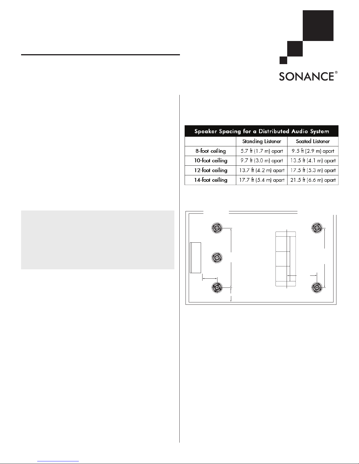
The following chart shows how far apart the speakers can be
placed at different ceiling heights while still providing goo d
coverage. The distances are based on ear heights of 62”
(1.5 m) for st anding liste ners and 40” (1 m) for seated listeners.
Home Theater Speaker Placement
Left & Right
Surround Speakers
6' – 10'
(2 - 3 m)
apart
TV
Left, Center
& Right
Speakers
6' – 10'
(2 - 3 m)
apart
Parts List
Your Original Series Medi um Ro und speakers inclu de th e
following:
• (2) Original Series Medium Round Speakers
• (2) Paintable grilles
• (2) Plastic paint plugs to protect speakers during painting
• (1) Mounting cutout template (in packaging)
Speaker Placement
Th e locatio ns of the spea kers shou ld be determin ed by
considering the prim ary listenin g l ocati on, the primary use for
the speakers (di stributed audio, 2-c hannel, or home theat er),
an d aest heti c valu es. Fo r opti mum result s, con tact y our
Authorized Sonance Dealer for advice.
Distributed Audio Placement
Sonance Original Series Medium R ound speak ers have very
smooth and predictable off -axis res ponse, increasing placement
options while providing excellent coverage in distributed audio
systems from a wide variety of i nstallation locations.
1'– 2'
(30 - 60 cm)
2'– 3'
(60 - 90 cm)
Figure 1: 5.1-channel home theater placement
Left, Center & Right Channels
• Place the left, center and right speakers from 1-2 feet (3060 cm) in front of the video screen, anywhere from 6 feet
to 10 feet (2–3 m) apart , with the center channel speaker
as close to midway between the left and right speaker s as
possible.
• Place the left & right speakers at lea st 2 to 3 feet (60–9 0 cm)
away from the side w alls.
• The main listening position should be bet ween 4 and 10 fee t
(1.2–3 m) away from the sp eakers.
• If necessary, pivot the tweeter and the woofe r of each spe aker
towards the listening positi on to maximize the soundstage.
The pivoting feature is avail able only on the Original Series
Medium Round 625R, 62 4R, 623R, 622R , and 621 R speakers.
The adjustable thre e-position tweeter swit ch is available on
the 625R, 624R, 623R, and 623R T L.
Use Figure 1 as a gui de.
2' – 6'
(.5 - 2 m)
1
Page 2
Left & Right
Left, Center
OR IGINAL SERIES MEDIUM ROUND SPEA KERS
Left & Right Surround Speakers (5.1-Channel System)
Locate th e left and ri ght surround speakers on the ceiling
between 2 and 6 feet (.6 - 2 m) beh ind the lis tenin g p ositi on.
The speakers sh ould be between 6 and 10 feet (2 - 3 m) apart.
Since the surround spea kers a re usually called -upon to cre ate
diffuse effects like the sound of win d or rain, they can be located
close to walls without adversely affecting sound quality.
• You can create a more diffuse, spacio us surround effect
by pivoti ng the tweete r and the woo fer towards a wall or
window, away from th e listen ers. This feature is available
only on the 625R, 624R, 623R, 622 R, and the 621R s peakers.
Use Figure 1 as a gui de.
Left & Right Surround and Surround Back Speakers
(7.1-Channel System)
• Left & Right Surround Spe akers: Place the left and right
surround speakers directly to the sides of the list ening
position, betwe en 6 feet and 10 feet (2 - 3 m) apart. The
speakers can be placed close to the si de wal ls.
• Surround Back Spea kers: Plac e the surround back speakers
between 2 and 6 feet (.6 - 2 m) behi nd the liste ning position.
The surr ound back spe akers should be closer together than
the left an d right su rroun d speakers -- between 3 an d 6 feet
(1 - 2 m) apart. Like the lef t and right su rround speakers, the
surround ba ck speakers can be located close to walls without
adversely affecting sound quality.
• You can crea te a more diffuse, spacious surroun d effect by
pivoting the tweeter and the woofer towards a wall or window,
away from t he listeners. This fe ature is availa ble only on the
Original Series Medium Round 625R, 624R, 623R, 622R, and
621R spe akers. T he adjustabl e three- position tweeter swit ch
is available on the 625R, 624R, 623R, and 62 3R TL.
Use Figure 2 as a gui de.
& Right
Speakers
6'– 10'
1'– 2'
(2 - 3 m)
apart
2'– 3'
(60 - 90 cm)
TV
(30 - 60 cm)
Figure 2: Left, Center, & Right Home Theater Speaker Placement
Surround Speakers
2' – 6'
(.6 - 2 m)
Surround
Back
Speakers
3' – 6'
(1 - 2 m)
apart
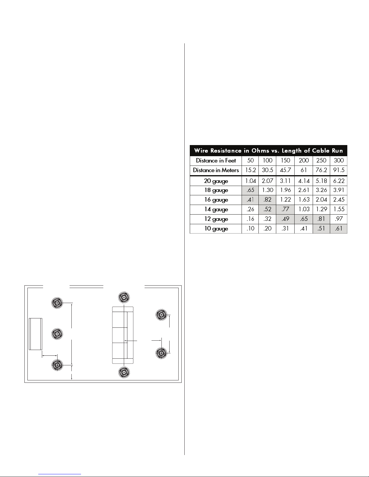
Wire Gauge
Extra resistance in the spe aker wire can make speakers sound
less dyn amic and redu ce definition of the bass frequencies. In
extreme case s, it can even atten uate high frequenci es. Also,
amplifier power is wasted in wire with extra r esist ance, reduci ng
your system’s maximum output level.
To prevent degrading sound qua lity, the total wire resistance
should be less t han 10% of the speaker’s imp edanc e. This
means that for an 8-ohm speak er, the tota l resi stanc e of the
wire should be less than 0 .8 ohm s.
Refer to the table be low to select the proper wire g auge for your
system.
Preparing the Installation Location
All Sonance speak ers are designed to be rela tively insensitive
to variation s in enclosure volume. To achieve the ul timate
performance from y our speakers, a sectio n of the ceiling
bay can be partitioned to form a back box. Bui lding such an
enclosure will create a dram atic imp rovement in your speaker s’
bass performance and power handling.
Ideal internal back box volume requirements:
0.62 ft³ (.0175 m³) overall size
Insulating the Ceiling Cavity
You can reduce sound transmission to adjacent rooms and
further improve speaker pe rform ance by inserting a sh eet of
unfaced fiberglass insulation over the back of the speaker.
To reduce noise prod uced by un supported drywall, install
fiberglass insulation in the ceiling bays adjacent to the speaker
location.
2
Page 3
OR IGINAL SERIES MEDIUM ROUND SPEA KERS
Optional Retrofit Enclosures
For insta llations wher e it isn’t possible to partition the ceiling
bay to form a back box (such as when you’re retrofitting
the speakers into an e xisting ceiling), you can effectively
reduce sound transmission into adj acent rooms by fitting the
speakers with the optional Medium Round Retrofit En closure
(part# 92343) or t he Medi um Roun d 6½” Woo den Enc losure
(part# 91688). These enclosures are designe d specifically to
be use d wit h these spe akers , and will noticeably reduce sou nd
“spillover” from the rea rs of t he speakers into adjacent rooms
and spaces.
Installing the Speakers
Before Installation: New Construction
For ins talla tions in new constru ction , Sonance recommends
using a Flex Bracket (part# 9233 7) to reserve a loc ation for
the speaker. The Flex B racke t has perforated wings that can be
positioned at any ang le around the bracket, and is nailed or
screwed to the studs. This serves as a guide for the drywall er
so that t he speaker ho le will be in the desired locat ion once the
drywall is installed.
Before Installation: Retrofit
1. Dete rmine the locati on for the speaker (see Speaker Pla cemen t
on page 1).
2. Perf orm an obstruction survey to be certain that the re are no
studs, conduit, pipes, heating ducts or air returns that will
interfere with the speaker.
3. Moun ting s pace r equir ements:
• Medium Round speakers: 8¼” (210mm) diameter cut-out;
4¾” (121mm) depth within the mounting cavity.
• Medium Round ThinLine
cut-out; 3
4. Posi tion the included cutout template wher e t he speaker is to
be located and pencil an o utline on th e ceil ing.
• If you are u nsure about o bstructions, drill a small hole in
the center of the ou tline and insert a coat hanger wire into
the hole to fe el-around for possible obstructions.
5. Cut the moun ting hole using a keyhole or drywall saw, and
run the speaker wires from the moun ting hole to the ampl ifier
location.
1
/32” (77mm) depth within the mounting cavity.
No te: Con sul t l oCal b u ild ing Cod es befo re runn ing spe ake r
wi res t hrou gh Ceil ing s .
Installation
Sonan ce Origi nal Ser ies Med ium Round speakers fea ture
exclusive FastMo unt tab s and an integral Roto-Lock
system for quick mount ing directly into existing ceili ngs and
walls.
Wa rNi N g:
Ca ut ion wh e n h and li n g t he s pe a ke r.
1. Remo ve the paint plug from the speaker.
2. Run speaker wire fro m each speaker t o the amplifier location.
th e edge s of the fas tMo un t tabs a re v er y sh a rp . use
®
speakers: 8¼” (2 10mm) diameter
®
mounting
3. Stri p ¼” - ½” (6mm - 12mm) of insulation fr om e ach speaker
lead. Twist the strands or tin the exposed wire with solde r
to ensure that there are no stray stran ds. (Stray s trand s that
touch each other can cause a short circuit that can damage
the amplifier.)
4. The speaker’s connector posts are spring-loade d. Push the
top of each connector p ost down to open the conne ctor and
insert the exposed wires into the holes in t he pos ts.
• The spea ker’s positive post is labeled with a r ed dot; the
negative post i s lab eled with a bla ck dot. Connect the
speaker wire to the termina ls on the speaker. Doublecheck that you co nnected amplifier “+” to spe aker “+ ” and
amplifier “–“ to speaker “–“.
5. Make s ure all the Roto-Lock clamps are in the full clockwise
position so that they are tucked within the mounting hole’s
border. Insert the speaker into the hole in the ceiling. The
Roto-Lock system can accomm odate a maximu m ceiling
material thickness of 1¼” (32mm).
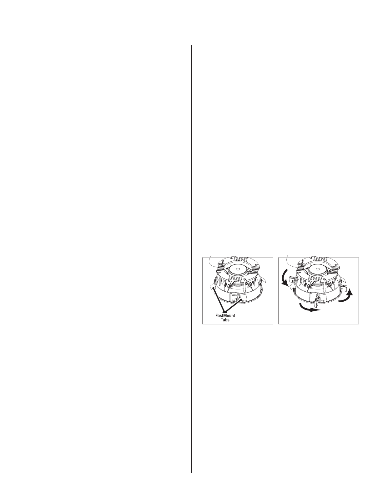
• The FastMount tabs wi ll pre vent the speaker from falling out
of the mounting hole, allow ing the installer to let go of the
speaker to pick up t ools o r othe r item s (see Figure 4).
No te: th e fast Moun t t a bs ar e d esig ned fo r o ne-tiMe use
on ly. if t he spe a ker i s reM o ved f roM the Moun tin g h ole , the
fa stM o unt t abs w ill d i sCo nneC t and r eMa i n in s ide t he wall s.
6. Tigh ten the four s crews on t he front of th e speaker baffle. T he
Roto-Lock clamps will automa tically rotate into pos ition and
begin clamping the speaker (see Fi gure 4 ).
• When you notice r esistance on the screws the speaker has
been clamped successfully.
Figure 4: Original Series Medium Round Speaker Installation
im por t aNt : alwa y s u s e l o w-t orqu e sett ing s . never ov er-
ti ght e n.
N
ot e: ad jus tin g the ten s ion of t he roto -loC k C l aMp s so
th at the s pea ker fraMe is f lat w ill h e lp ens ure t hat t he gri lle
Co nta C ts t he Cei l ing all the wa y ar o und th e sp e ake r fo r a
pr ope r fit.
7. Atta ch the gril le after the speaker has been installed. Insert
about half of the grille into the groove at the edge of the
speaker. Gently fit th e remai ning ha lf of the grille by wo rking
around the speaker, fitting the grille into t he groove as you
go.
• You ca n adjust the torque to the Roto-Lock screws to
achieve a proper grille fit.
3
Page 4

OR IGINAL SERIES MEDIUM ROUND SPEA KERS
Painting the Speakers and Grilles
All Sonanc e Origina l Series Medium speakers come from the
factory fitted with a p lasti c “paint plug. ” Use the paint plug to
protect the speaker drivers while the flange is being painted
along with the wall. You can paint the speakers and grilles
before installing them, which will elim inate the “pain t sca r” if
the speak er ever needs to be removed f or service. Y ou can also
paint the spe akers after insta llati on, but before the grilles are
attached.
Sonance alway s suggests paint ing the grille separately from
the speake r. Before paint ing, caref ully remove the under-grille
cloth. It is held in place with a light tacking glue that makes it
easy to remove.
Spray the grilles with thinned paint (5 parts thinner to 1 part
paint), being careful no t to plug the ho les. Too heavy a coat of
paint on the grille will adversely aff ect the sound of the speaker.
Once the grilles and fla nge are painted and dry, rep lace the
under-grille cloth, rem ove the paint pl ug from the spea ker
flange and install the grille.
Speaker Adjustments
Pivoting Woofer and Tweeter
All Original Ser ies Me dium Round speakers have a p ivoti ng
woof er assembly. T he pivot ing woofer-tweet er as sembly is
available on Original Serie s Medium Round 625 R, 624R, 623R ,
622R and 621R speakers. The 3-position tweeter adjustme nt
switch is avai lable on the 625R, 624 R, 623R, and 623R TL
speaker and lets you ba lance the speaker’s hi gh-frequency
energy better to compliment the room’s setup and acoustics.
These pivot ing drivers allow you to d irect sound towar d or away
from the listening area.
To pivot the woofer:
1. Appl y pressure on the outer edge of the tweet er sup port
bracket, as sh own below in Figure 5. Do not tou ch or apply
pressure to the woofer cone.
Figure 5: Pivoting the woofer and tweeter
Tweeter Level Control
The Orig inal Seri es 625R, 624R, 623R, and 623R TL speakers
feature a twee ter level control switc h (see F igure 6) that lets you
boost or cut the tweeter’s level b y 3dB. This al lows you to adjust
the speake r’s brightness to better match your liste ning room or
personal taste.
Once you have installed the spe akers, listen to a variety of
music that you are familiar with. If the music all tends to sound
too bright or dull, use the Tweeter Level Control to compe nsate .
If some recordings sound du ll and some sound bright the
speaker i s accurately repro ducing differences in the recor dings,
and you should leave the c ontrol in th e midd le (0d B) pos ition .
If you’re using the spea kers in stereo or as the fron t L/C/R
speakers in a home theate r, pivot the woof er and/or tweeter
directly towards the listening area. This can be espec ially helpful
if the speakers are widely-separa ted an d the m usic f ails t o blen d
into a central sonic image.
If you’re using th e speaker s as surround channel speakers in a
home the ater, you can c reate a mor e diffuse, spaci ous surround
effect by aim ing the woofers and/or tweete r towards a wall or
window, away from the listeners.
Tweeter
Control
Figure 6: Tweeter level control
4
Page 5

OR IGINAL SERIES MEDIUM ROUND SPEA KERS
Specifications
625R
Tweeter: 1” ( 25mm) Ber yllium dome, Ferroflui d-cooled,
pivoting
Woofer: 6½” (165 mm) Beryllium cone, rubb er surround,
pivoting
Frequency Response: 40Hz – 20kHz ± 3dB
Impedance: 6 Ohms nominal; 4 Oh ms min imum
Power Handling: 5 watts minimum; 150 Watts maximum
Sensitivity: 90dB SPL (2.83V 1 me ter)
Grill Material: Perforated aluminum
Adjustments: ±3dB Tweeter level
Dimensions (Dia. x Depth): 9¾” (248mm) x 4¾” (1 21mm)
Cutout Diameter: 8
Shipping Weight: 12 lbs . (5.4 5kg) P air
624R
Tweeter: 1” (25mm) Alu minum dome, Ferrofluid-cool ed,
Woofer: 6½” (16 5mm) Coated ca rbon fiber con e, rubber
Frequency Response: 43Hz – 20kHz ± 3dB
Impedance: 6 Ohms nominal; 4 Oh ms min imum
Power Handling: 5 watts minimum; 140 Watts maximum
Sensitivity: 90dB SPL (2.83V 1 me ter)
Grill Material: Perforated aluminum
Adjustments: ±3dB Tweeter level
Dimensions (Dia. x Depth): 9¾” (248mm) x 4¾” (1 21mm)
Cutout Diameter: 8
Shipping Weight: 11 lbs . (5.0 kg) Pa ir
623R
Tweeter: 1” (25mm) Silk dome, Ferrofl uid-c ooled, pivoting
Woofer: 6½ ” (1 65mm) Car b on f i ber c one, rubb er
Frequency Response: 43Hz – 20kHz ± 3dB
Impedance: 8 Ohms nominal; 6 Oh ms min imum
Power Handling: 5 watts minimum; 135 Watts maximum
Sensitivity: 90dB SPL (2.83V 1 me ter)
Grill Material: Perforated aluminum
Adjustments: ±3dB Tweeter level
Dimensions (Dia. x Depth): 9¾” x 4¾” (248 mm x 12 1mm)
Cutout Diameter: 8
Shipping Weight: 10 lbs . (4.5 kg) Pa ir
622R
Tweeter: 1” (25mm) Silk dome, Ferrofl uid-c ooled, pivoting
Woofer: 6½ ” (16 5mm) Polyp ropyl e ne co ne, r u bber
Frequency Response: 45Hz – 20kHz ± 3dB
Impedance: 8 Ohms nominal; 6 Oh ms min imum
Power Handling: 5 watts minimum; 125 Watts maximum
Sensitivity: 89dB SPL (2.83V 1 me ter)
Grill Material: Perforated aluminum
Adjustments: None
Dimensions (Dia. x Depth): 9¾” (248mm) x 4¾” (1 21mm)
Cutout Diameter: 8
Shipping Weight: 10 lbs . (4.5 kg) Pa ir
1
/4” (210mm)
pivoting
surround, pivoting
1
/4” (210mm)
surround, pivoting
1
/4” (210mm)
surround, pivoting
1
/4” (210mm)
621R
Tweeter: ¾” (19mm) Silk dome, Ferrofluid-cooled
Woofer: 6½ ” (16 5mm) Polyp ropyl e ne co ne, r u bber
surround, pivoting
Frequency Response: 50Hz – 20kHz ± 3dB
Impedance: 8 Ohms nominal; 6 Oh ms min imum
Power Handling: 5 watts minimum; 100 Watts maximum
Sensitivity: 88dB SPL (2.83V 1 me ter)
Grill Material: Perforated aluminum
Adjustments: None
Dimensions (Dia. x Depth): 9¾” (248mm) x 4¾” (1 21mm)
Cutout Diameter: 8
1
/4” (210mm)
Shipping Weight: 9 lbs. (4.1k g) Pai r
623R TL
Tweeter: 1” (25m m) silk dome, f errof luid cooled , pivoting
Woofer: 6½ ” (165m m ) carbo n fiber c o ne, ru b ber
surround, pivoting
Frequency Response: 43Hz-20kHz ±3dB
Impedance: 8 ohms nominal; 6 oh ms min imum
Power Handling: 5 watts minimum; 135 watts maximum
Sensitivity: 90dB (2.83V/1 meter)
Grille: Perforated aluminum
Adjustments: ±3dB Tweeter level
Dimensions (Dia. x Depth): 9¾” x 3” (248m m x 76m m)
Cutout Diameter: 8
1
/4” (210mm)
Shipping Weight: 10 lbs (4.5k g) pai r
622R TL
Tweeter: 1” (25m m) silk dome, f errof luid cooled , pivoting
Woofer: 6½ ” (1 65mm) pol y propy lene cone , ru b ber
surround, pivoting
Frequency Response: 45Hz-20kHz ± 3dB
Impedance: 8 ohms nominal; 6 oh ms min imum
Power Handling: 5 watts minimum; 125 watts maximum
Sensitivity: 89dB (2.83V/1 meter)
Grille Material: Perforated aluminum
Adjustments: None
Dimensions (Dia. x Depth): 9¾” x 3” (248m m x 76m m)
Cutout Diameter: 8
1
/4” (210mm)
Shipping Weight: 10 lbs (4.5k g) pai r
621R TL
Tweeter: ¾” (19mm) silk dome, ferrofluid cooled
Woofer: 6½ ” (1 65mm) pol y propy lene cone , ru b ber
surround
Frequency Response: 50Hz-20kHz ±3dB
Impedance: 8 ohms nominal; 6 oh ms min imum
Power Handling: 5 watts minimum; 100 watts maximum
Sensitivity: 88dB (2.83V/1 meter)
Grille Material: Perforated aluminum
Adjustments: None
Dimensions (Dia. x Depth): 9¾” x 3” (248m m x 76m m)
Cutout Diameter: 8
1
/4” (210mm)
Shipping Weight: 9 lbs ( 4.1kg ) pair
5
Page 6

Technical Assistance and Service
If you any have questions about the operation or installation of
this product, please call our technical assistance department on
any business day at (800) 582-0772 or (949) 492-7777; from
7 a.m. to 5 p.m., PST.
If your speakers should need repair or service, contact your
Sonance Authorized Dealer for help, or use the following
procedure:
1. Prio r to calling, note the pro duct’ s model number, serial
number, purchas e date, and the name and address of the
dealer where you purchased the product.
2. Cont act our Technical Assistance Department at the abov e
number(s) and describe the problem the unit is experiencing.
If applicable, they will issue a Return Authorization Number.
im por t aNt : you M ust h ave p rio r aut hor i zat i on t o ret urn y our
sp eak e r to so nan Ce!
3. If you’re directed to return the unit to Sonance for repair,
pack the unit in its original shipping carton. If nee ded,
you can obtain replacement packaging from us for a smal l
charge. Note: it is best if you pla ce the box into an addi tional
outer “o vercarton” before shipment t o minimize a chance of
theft in sh ipment. Please include a copy of the original bill of
sale inside the package.
4. Cont act a package deliv ery company such as United Parcel
Service or Federal Express to arrange prepaid (not collect)
shipping. Do not use the U .S. Po stal S ervice.
im por t aNt : fre i ght C oll e Ct s h ipM e nts w ill b e ref u sed .
5. Writ e the Return A uthorization N umber on the outside of the
shipping carton.
6. Ship the package d unit to:
Quality Assurance Department
Sonance
212 Avenida Fabricante
San Clemente, CA 92672-7531
OR IGINAL SERIES MEDIUM ROUND SPEA KERS
6
Page 7

OR IGINAL SERIES MEDIUM ROUND SPEA KERS
Sonance warrants t o the fir st end-user purchaser that this Sonance-br and product (“Product”), when p urcha sed from an aut horiz ed
Sonance Dealer /Dist ributor, will be free from d efect ive workm anshi p and mat erial s for the life of the Produc t. Sonance wil l at its
option and expense either repair the defect or replace the Pro duct with a ne w or remanufactured Prod uct or a reaso nable equivale nt.
TO THE EXTENT PERMI TTED BY LAW, THE WARRANTY SET FORTH ABO VE IS IN LIEU OF, AND EXCLUS IVE OF , ALL OTHER
WARRANTIES, EX PRESS OR IMPL IED, AND IS THE SOLE AND EXCLUSIVE WARR ANTY PROVIDED BY SONANCE. ALL OTHER EXP RESS
AND IMPLIED WAR RANTI ES, INCLUDING THE IMPL IED WARRANTIES OF MERC HANTA BILITY, IMPLIED WARRANTY OF FITNESS FOR
USE, AND IMP LIED WARRANTY OF FITNESS FOR A PARTI CULAR PURPOSE ARE SPECIFI CALLY EXCLUDED. No one i s au thorized to
make or modify any w arranties on behalf of S onance.
The warranty stated above is the sole and exclusive remed y and Sonanc e’s performance shall constitute full and final s atisfaction
of all obliga tions, liabilities and claim s with respe ct to the Product. IN ANY EV ENT, SONANC E SHALL NOT BE LIABLE FOR
CONSEQUENTIAL, INCIDENTAL , ECONOMIC, PROPERTY, BODILY INJURY, OR PERSONAL INJURY DAMA GES AR ISING FROM THE
PRODUCT, ANY BREACH OF THIS WARRANTY OR OTHERWISE.
This warran ty statement gives you specific lega l rights, and you may have o ther rights which v ary from state to state. Some sta tes do
not allow t he exclu sion of imp lied warrant ies or limitations of remedies, so the above exc lusio ns and limitations may not apply. If
your state does not allow disclaim er of impl ied w arranties, the duration of such implie d war ranti es is limited to period of Sonance’s
express warranty.
Additional Li mitations and Exclusions fro m Warranty Cover age: The wa rranty described above is n on-transferable, applies only to
the initial installation of the Produ ct, does not include installation of any repaired or replaced Product, doe s not inclu de dam age
to allied or assoc iated equ ipment wh ich may result for any reason f rom use with this Prod uct, and does not incl ude labor or parts
caused by ac cident, disaster, negligence, improper installation, misuse (e.g. overdriving the amplifier or spe aker, ex cessi ve heat or
cold or humidity, outdoor installation), or from service or repair which has not been authorized by Sonance.
Obtaining Authorized Service: To qualify for the warranty, you must (1) contact you r authorize d Sonance Dealer/Installer or call Sona nce
Customer Service at (800) 582-0772 within the warranty period, (2) obtain a return merchandise number (RMA), and (3) deliver the Product to
Sonance shipping prepaid during the warranty period, together with the original sales receipt, invoice or other satisfactory proof of purchase.
©2010 Son ance. All r ights rese rved.
Sonanc e, FastMou nt, and Rot o-Lock are re gistere d tradem arks of Dana I nnovati ons.
Due to conti nuous pr oduct impr ovement , a ll featu res and speci ficatio ns are subj ect to chan ge without no tice.
For the late st Sonan ce product sp ecifica tion inf ormatio n v isit our we bsite: www .sonanc e.com
SONANC E • 21 2 Avenid a F abrican te • San Cleme nte, CA 926 72-7531 US A
(800) 582 -7777 or (9 49) 492-77 77 • FAX: (949 ) 3 61-5151 • T echnica l S upport: (800) 582- 0772
www.sonance.com
33-548 1 Rev. 10/ 2010
7
 Loading...