

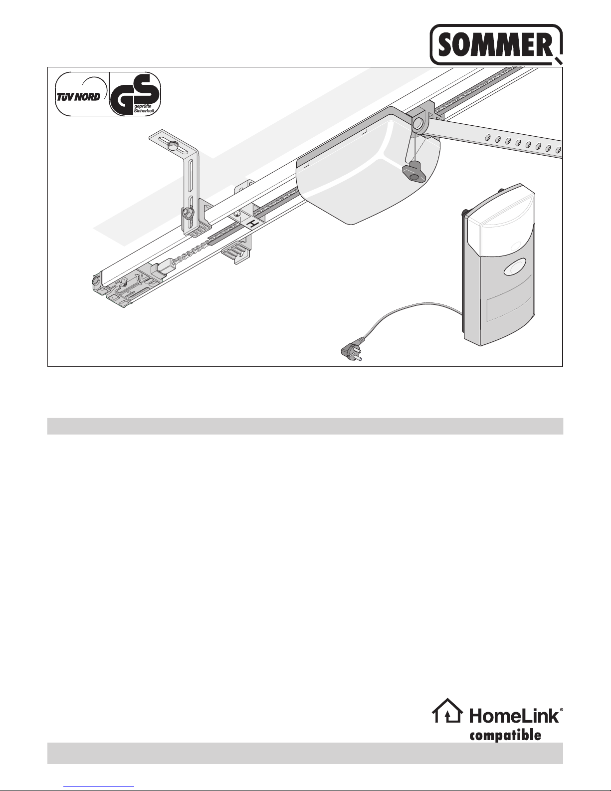
SOMMER duo vision 500, duo vision 650, duo vision 800, duo rapido 650 Installation And Operating Instruc
Page 1
t
Installation and Operating Instructions 1 - 30
t
46758V001-262012-0-OCE-Rev.A_GB
duo vision 500, 650, 800
duo rapido 650
Page 2

– 2
t
Table of contents
General Information ...................................................... 3
Symbols ........................................................................................... 3
Safety instructions ............................................................................ 3
General ...................................................................................... 3
Storage ...................................................................................... 3
Operation ................................................................................... 3
Radio remote control ................................................................. 3
Type plate .................................................................................. 3
Intended use .................................................................................... 3
Max. permissible door dimensions * ................................................ 4
Technical data .................................................................................. 4
EU Declaration of Conformity ........................................................... 4
Scope of supply ................................................................................ 5
Declaration of Installation ................................................................. 6
Installation preparations ............................................... 7
Safety instructions ............................................................................ 7
Tools required ................................................................................... 7
Personal safety equipment ............................................................... 7
Install slip door safeguard or emergency release lock ..................... 7
Installation ...................................................................... 8
Safety instructions ............................................................................ 8
Door types and accessories* ........................................................... 8
Tips for installation ........................................................................... 8
Selection of installation variants ....................................................... 9
Preinstallation of installation variant A/C .......................................... 9
Preinstallation of installation variant B ........................................... 10
Installation (example: installation variant B) ................................... 12
Mount the controller housing and connect ..................................... 14
Selection of the installation variant .......................................... 14
Installation variant A/B ............................................................. 14
Installation variant C ................................................................ 15
Install the wall socket. .................................................................... 16
Install and connect the additional button ........................................ 16
Initial operation ............................................................ 17
Safety instructions .......................................................................... 17
Adjust door end positions for CLOSE + OPEN .............................. 17
Programming the drive ................................................................... 17
Checking the emergency release ................................................... 18
Check the force settings ................................................................. 18
Programming the hand-held remote control ................................... 18
Mount the information sign ............................................................. 18
Attaching the warning sign ............................................................. 19
Operation / Use ............................................................ 20
Safety instructions .......................................................................... 20
Open door ...................................................................................... 20
Close door ...................................................................................... 20
Pulse sequence of door movement ................................................ 20
Emergency release ........................................................................ 20
Control unit reset ............................................................................ 20
Intermediate stop ........................................................................... 21
Safety stop 1
(power cut-off) .......................................................................... 21
Safety stop 2
(safety input) ............................................................................ 21
Overload protection ........................................................................ 21
Operation after a power failure ....................................................... 21
Radio receiver ................................................................................ 21
Safety instructions ................................................................... 21
Display and button explanation ................................................ 21
Programming the hand-held remote control ............................ 22
Deleting a hand-held remote control button from the
radio receiver ........................................................................... 22
Deleting a channel from the radio receiver .............................. 22
Deleting the radio receiver memory ......................................... 22
Connecting external antenna ......................................................... 22
What is button 2 for? ...................................................................... 22
Functions and connections ........................................ 23
General information ........................................................................ 23
Obstacle detection (DIP 1, 2 + 3) ................................................... 23
Drive behavior when opening the door .................................... 23
Drive behavior when closing the door ...................................... 23
Connecting photo eyes .................................................................. 23
Connect button 2 (DIP 2) ............................................................... 23
Connect warning light (DIP 4) ........................................................ 23
Direct connector (button 1) ............................................................. 24
Prewarning time (DIP 5) ................................................................. 24
Backjump (DIP 6) ........................................................................... 24
Dened opening and closing (DIP 7) ............................................. 24
Partial opening (DIP 8) ................................................................... 25
Connecting external antenna ......................................................... 25
TorMinal interface ........................................................................... 25
Carriage circuit board ..................................................................... 25
Maintenance and care ................................................. 26
General information ........................................................................ 26
Cleaning chains and drive unit rail ................................................. 26
Replacing light bulbs ...................................................................... 26
Replacing fuse
(warning light connection) .............................................................. 26
Regular testing ............................................................................... 27
Miscellaneous .............................................................. 28
Disassembly ................................................................................... 28
Disposal ......................................................................................... 28
Warranty and customer service ..................................................... 28
Troubleshooting .......................................................... 29
Tips on troubleshooting .................................................................. 29
Page 3
– 3
t
Symbols
ATTENTION SYMBOL:
Important safety instructions!
Attention - to ensure personal safety, it is important to
observe all instructions. Save these instructions!
NOTE SYMBOL:
Information, useful advice!
Refers to a respective picture in the introduction or main text.
Safety instructions
General
¾ These installation and operating instructions must be read, understood
and complied with by persons who install, use or perform maintenance
on the drive.
¾ Installation, connection and initial commissioning of the drive may only
be carried out by technically knowledgeable persons.
¾ All lines are to be rmly secured, for example, against moving.
¾ Only install the drive on correctly aligned and weight-balanced doors.
An improperly aligned door can cause serious injuries or damage the
drive.
¾ The manufacturer assumes no liability for injuries, damage or break-
downs that occur due to non-compliance with the installation and
operating instructions.
¾ Ensure that these installation and operating instructions are kept in an
easily accessible location within the garage.
¾ Always ensure compliance with accident prevention regulations and
current standards in each respective country.
¾ Follow and comply with the “ASR A1.7 Technical Regulations for
Workplaces” of the committee for workplaces (ASTA). (Applies to
operators in Germany.)
¾ Always disconnect the mains plug before working on the drive.
¾ Only use OEM (Original Equipment Manufacturer) spare parts,
accessories and mounting material.
Storage
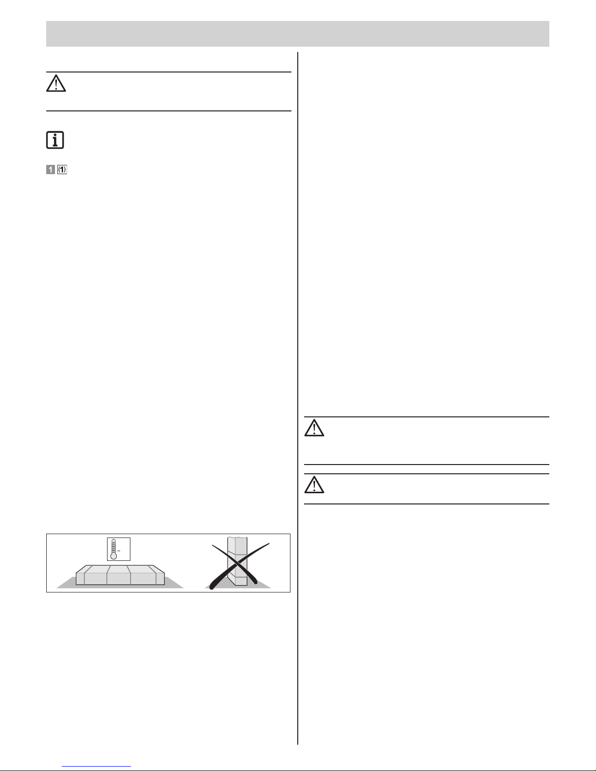
¾ The drive must be stored indoors in an enclosed, dry area at a room
temperature of –20 - +50 °C.
¾ The drive should be stored horizontally.
+50°
20°
Operation
¾ The drive may only be operated if a non-hazardous force value has
been set. This force value must be set low enough to ensure that the
closing force poses no risk of injury.
¾ Never put your hand near the door when it is moving or near moving
parts.
¾ Continuously monitor the door while it is in motion and keep all persons
away from it until the door is completely opened or closed.
¾ Only pass through the door only once it is completely open.
¾ Actuating the emergency release can lead to uncontrolled door
movements if springs are weakened or broken, or if the door has not
been optimally weight-balanced.
¾ There is a risk of persons being crushed or cut by the mechanism or
sharp edges of the door.
¾ If the garage does not have a separate entrance or the garage door
does not have a built-in slip door, you must install an emergency
release (release lock or Bowden cable) that can be operated from
outside.
Radio remote control
¾ The remote control must only be used for devices and systems in which
radio interference will not endanger people, animals or objects, or the
risk is reduced by other safety devices.
¾ The user must be made aware that systems that pose an accident risk
should only be operated – if at all – by remote control if the user can
actually see the door.
¾ The radio remote control may only be used if the door’s movement
can be watched and no persons or objects are within the range of
movement.
¾ Store the hand-held transmitter so that unintended operation, e.g.,
by children or animals, is impossible.
¾ The operator of the radio system is not protected from faults due to
other telecommunications equipment or devices (e.g. radio-controlled
systems that are licensed to operate in the same frequency range).
If substantial interference occurs, please contact your appropriate
telecommunications ofce which has radio interference measuring
equipment (radiolocation).
¾ Do not operate the hand-held transmitter in areas with sensitive radio
communications or systems (e.g. airports, hospitals).
Type plate
¾ The type plate is located on the cover of the controller housing.
¾ The type plate shows the exact type designation and the date of
manufacture (month/year) of the drive.
Intended use
CAUTION! RISK OF IRREPARABLE DAMAGE TO THE DRIVE!
Do not open or close doors with the drive unless the
counterbalance is properly adjusted (springs tensioned).
Otherwise, you will damage or destroy the motor
(transmission).
CAUTION! RISK OF DEATH!
Remove all cords or straps necessary to operate the door
by hand.
¾ The drive is intended exclusively to open and close doors. Any other
use does not constitute intended use. The manufacturer accepts no
liability resulting from use other than intended use. The user bears the
sole responsibility for any risk involved. It also voids the warranty.
¾ Doors automated with an operator must must comply with the valid
standards and directives: e.g. EN 12604, EN 12605.
¾ The drive may only be used if it is in perfect working order and is used
as intended, in conscious observation of safety and hazards and in
accordance with the installation and operating instructions.
¾ Malfunctions which could affect safety must be corrected immediately.
¾ The door must be stable and rigid, meaning that it may not bend or
twist when being opened or closed.
¾ The drive cannot compensate for defects in the door or incorrect
assembly or installation.
¾ Only use the drive in a dry, non-hazardous area.
¾ Do not install the drive in areas with a corrosive atmosphere
(e.g. salty air).
General Information
Page 4
General Information
t
– 4
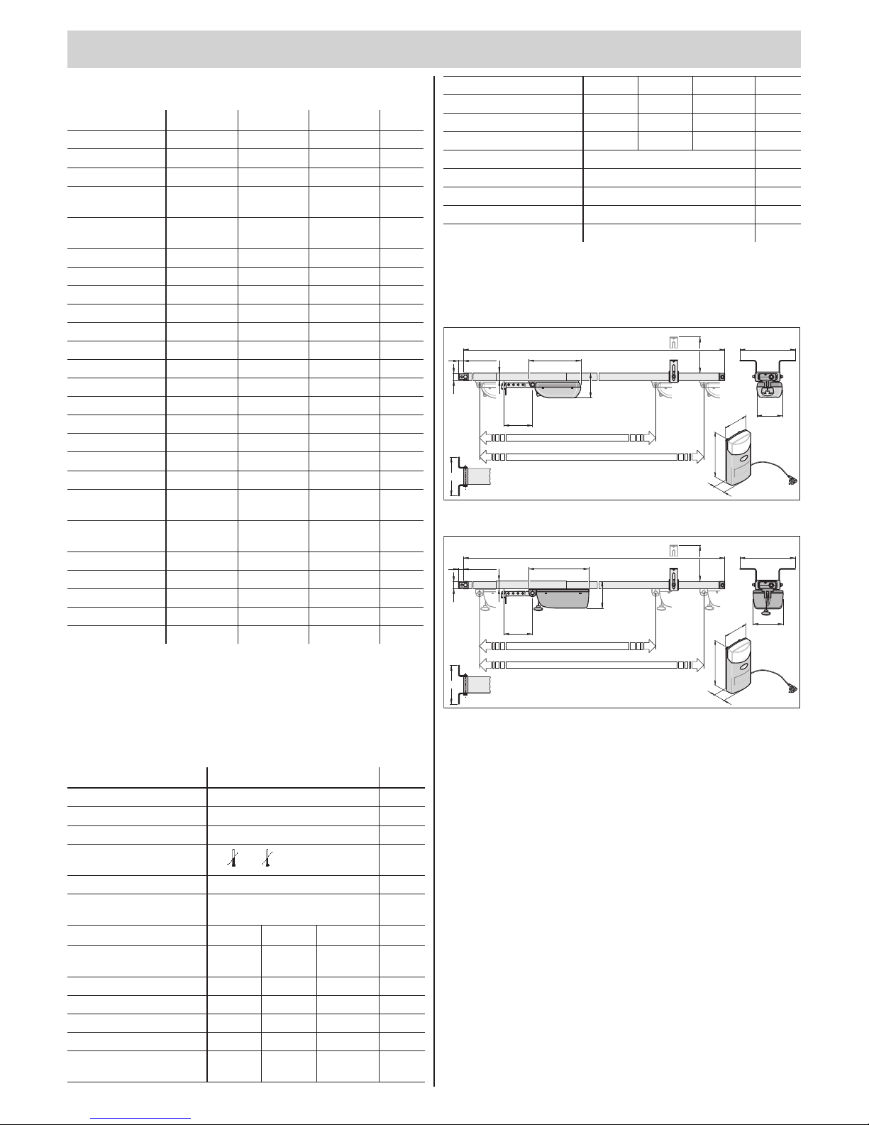
Max. permissible door dimensions *
500 650*** 800
Unit
Max. width
Swinging door 3500 5000 5500 mm
Sectional door 3500 5000 5500 mm
Hinged double
door **
- 2800 2800 mm
Side-sectional or
roller door
• Rails 2600 2350 2350 2350 mm
• Rails 3000 2750 2750 2750 mm
• Rails 3400 3150 3150 3150 mm
Up-and-over door - 4000 4500 mm
Approx. height
Swinging door
• Rails 2600 2600 2600 2600 mm
• Rails 3000 3000 3000 3000 mm
• Rails 3400 3400 3400 3400 mm
Sectional door
• Rails 2600 2350 2350 2350 mm
• Rails 3000 2750 2750 2750 mm
• Rails 3400 3150 3150 3150 mm
Hinged double
door **
- 2800 3000 mm
Side-sectional or
roller door
2300 3000 3000 mm
Up-and-over door
• Rails 2600 - 1900 1900 mm
• Rails 3000 - 2300 2300 mm
• Rails 3400 - 2700 2700 mm
Operating time 15 15 15 %
* Door in accordance with EN 12604, EN 12605
** With standard hinged double door tting, part no. 1501. For taller
doors, correspondingly longer rails or rail extensions must be
installed. Please ask you specialist dealer.
*** duo 650 and rapido 650
Technical data
500, 650, 800
Unit
Rated voltage 230 V/AC
Rated frequency 50 / 60 Hz
Lighting Max. 32 V, max. 18 W, BA 15s
Operating temperature
range
-20 - +50
°C
Protection type IP 20
Working environmental
emissions value
< 75 dBA – drive only
500 650 800
Max. tension and
compress. force
500 650 800 N
Rated tension force 150 195 240 N
Rated current consumption 0,5 0,7 0,8 A
Rated wattage 110 150 160 W
Max. speed 150 180/240* 130 mm/s
Power consumption,
stand-by
~ 7 ~ 2 ~ 2 W
Weight:
Rails 2600 16,0 16,0 16,0 kg
Rails 3000 17,4 17,4 17,4 kg
Rails 3400 18,4 18,4 18,4 kg
Package (L x W x H):
Drive 790 x 160 x 160 mm
Rails 2600 1665 x 160 x 50 mm
Rails 3000 1860 x 160 x 50 mm
Rails 3400 2060 x 160 x 50 mm
*du rapido 650
The force limitation, safety input 1 and 2 correspond to performance level C,
category 2.
duo vision 500, 650
375
252
120
2600
3000/3400
30
max.22,5
max.
214
3240 /3640 /4040
35
1
50
300
9
0
176
245
115
duo vision 800
375
2600
3000/3400
30
max.22,5
max.
214
3240 /3640 /4040
35
1
50
300
9
0
176
125
270
137
252
EU Declaration of Conformity
www.sommer.eu/mrl
Page 5
General Information
t
– 5
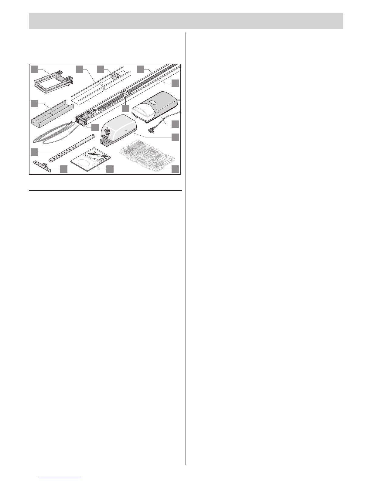
Scope of supply
The actual scope of supply may vary depending on the design of the drive.
Package 1
D
M
on
t
ag
e
und
B
etrieb
s
sa
nleitung
1
34
D
119
8
10 5
1
2
3
3
12
13
4
6
7
Item Name Quantity
1. Controller housing
(button, power cable, lighting)
1
2. Carriage (chain guide) 1
3. C-track (uncoated) 2
4. Connecting sleeve (uncoated) 1
5. Guide idler “H” 1
6. Guide idler “V” 1
7. Chain with chain guide 1
8. Push rod 1
9. Door bracket 1
10. Ceiling suspension bracket 1
11. Installation and Operating Instructions 1
12. Installation bag 1
13 Slide-in part with control cable
(length 5,000 mm)
1
Page 6
General Information
t
– 6
Declaration of Installation
for the installation of an incomplete machine
in accordance with the Machinery Directive 2006/42/EC, Appendix II, Section 1 B
SOMMER Antriebs- und Funktechnik GmbH
Hans - Böckler - Straße 21 - 27
73230 Kirchheim unter Teck
Germany
hereby declares that the controller
duo / duo rapido,
as of the identication duo / duo rapido 01/10, complies with the Machinery Directive 2006/42/EC and is specied for
installation in a door system.
• The following fundamental safety requirements have been applied and observed in accordance with Appendix I:
- General principles No. 1
- 1.2 Safety and reliability of control units
Safety input I terminals 7 + 8: Cat 2 / PL C
Internal force limitation Cat 2 / PL C
Safety categories in accordance with EN 13849 - 1:2008
• Compliant with the regulations of the EC Building Products Guideline 89/106/EC.
For the operating forces part, the respective initial testing has been carried out in consultation with recognized
inspecting authorities. In doing so, the harmonized standards EN 13241-1, EN 12453 and EN 12445 have been
applied. For the tested combinations, refer to the “Reference list” table in the Internet under www.sommer.eu.
• Compliant with the Low Voltage Directive 2006/95/EC.
• Compliant with the Directive on Electromagnetic Compatibility 2004/1 08/EC.
• The technical documentation was drawn up in accordance with Appendix VII B.
The product may only be put into operation after it has been established that the door system complies with the
regulations of the Machinery Directive.
Kirchheim, 12/29/2009
Jochen Lude
Responsible for documents
Page 7
– 7
t
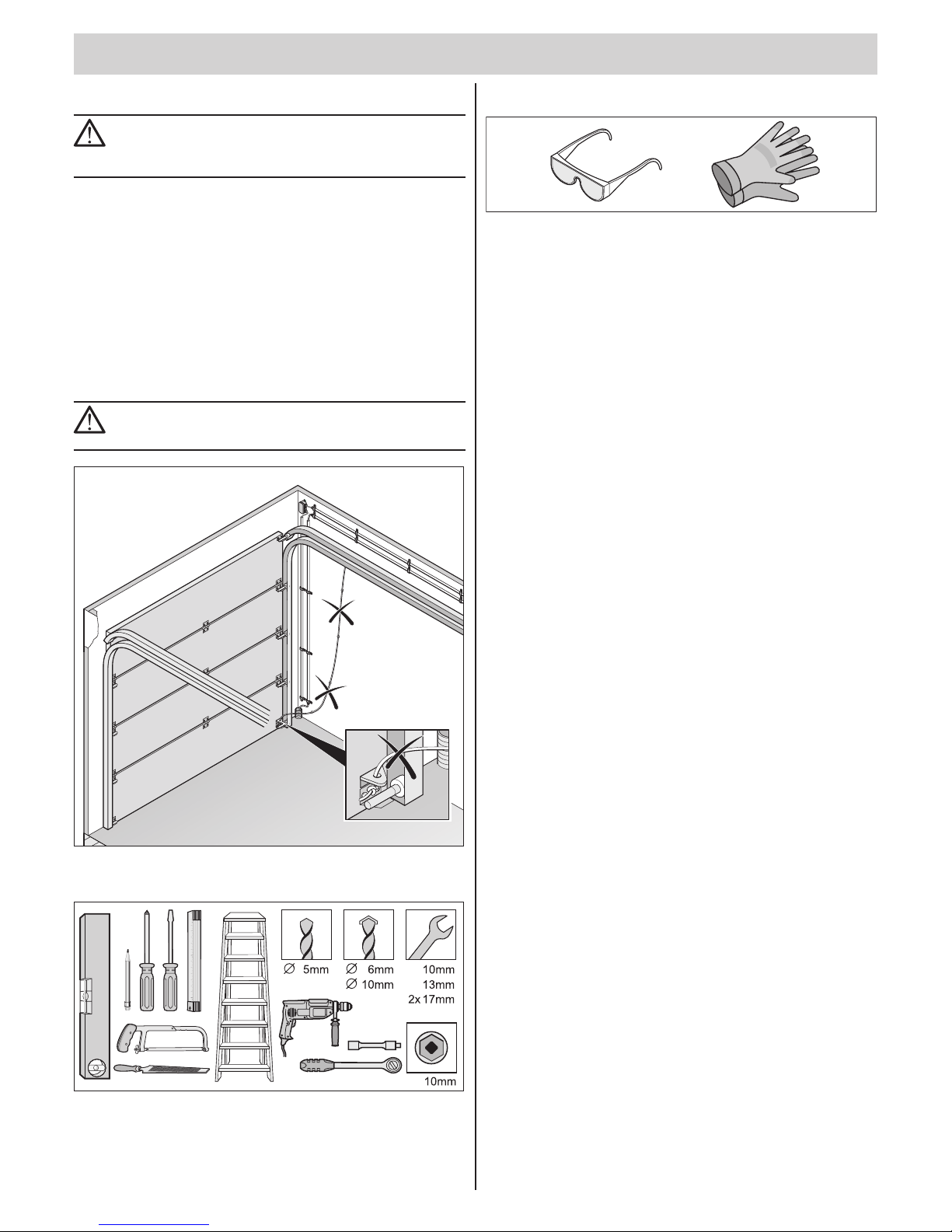
Safety instructions
ATTENTION!
Important instructions for safe installation. Observe all
installation instructions – improper installation can lead to
serious injuries!
¾ The mains supply line that has been provided may not be shortened
or extended.
¾ The voltage of the power source must correspond with the voltage
listed on the drive type plate.
¾ All devices to be connected externally must have a safe isolation
of the contacts from the mains voltage supply, in accordance with
IEC 60364-4-41.
¾ Live parts of the drive (voltage-carrying parts, e.g. C-rail) may not be
connected to the ground or with live parts or grounding conductors of
other electrical circuits.
¾ Wiring for external devices must be installed in accordance with
IEC 60364-4-41.
CAUTION! RISK OF DEATH!
Remove all cords or straps necessary to operate the door
by hand.
Tools required
Mit SOMMER sind Sie immer gut ausger
ichtet!
Personal safety equipment
¾ Safety glasses (for drilling).
¾ Protective gloves (e.g. when handling cut-off pieces of perforated strip
steel).
Install slip door safeguard or
emergency release lock
• There is a slip door installed in the door, but no slip door safeguard.
⇒ Install slip door safeguard (see accessories instructions).
• There is no slip door in the door and no second entrance to the garage.
⇒ Install an emergency release lock or Bowden cable to enable
unlocking from outside (see accessories instructions).
Installation preparations
Page 8
– 8
t
Safety instructions
ATTENTION!
Important instructions for safe installation. Observe all
installation instructions – improper installation can lead to
serious injuries!
ATTENTION!
After installation, it is imperative that you check the drive to
ensure that it has been correctly adjusted and that it reverses
upon contacting a 50 mm high object on the oor.
¾ The drive may only be installed, connected and commissioned by
qualied technicians.
¾ Do not move the gate if there are people, animals or objects in the area
of movement.
¾ Keep children, disabled persons and animals away from the door.
¾ Wear safety glasses when drilling the fastening holes.
¾ Cover the drive during drilling to prevent penetration of dirt.
ATTENTION!
Walls and ceiling must be solid and stable. Only install the
drive on a correctly aligned door. An incorrectly aligned door
could cause serious injury.
¾ Doors must be stable in themselves, since high traction and
compression forces are encountered. Reinforce lighter doors made of
plastic or aluminum if necessary before installation. Ask a specialist
retailer for advice.
¾ Remove or disable door locks.
¾ Use only approved fasteners (e.g. anchor ttings, bolts). The fasteners
must be suitable to the material of the ceilings and walls.
¾ Check that the door runs smoothly.
¾ The door must be counterbalanced.
TEST:
Half-open the door by hand. The door must remain in this
position. If the door moves up or down, re-adjust the door
mechanically. Ask a specialist retailer for advice.
Check the distance between the door's highest point (THP, see graphic 11)
and the ceiling. The distance between the THP and the lower edge C must
be between 5 mm and 65 mm; the angle of the door arm must be max. 30°
(see graphic 11). If the distance is less than this, the drive must be moved
back and a longer push rod must be installed. Ask a specialist retailer for
advice.
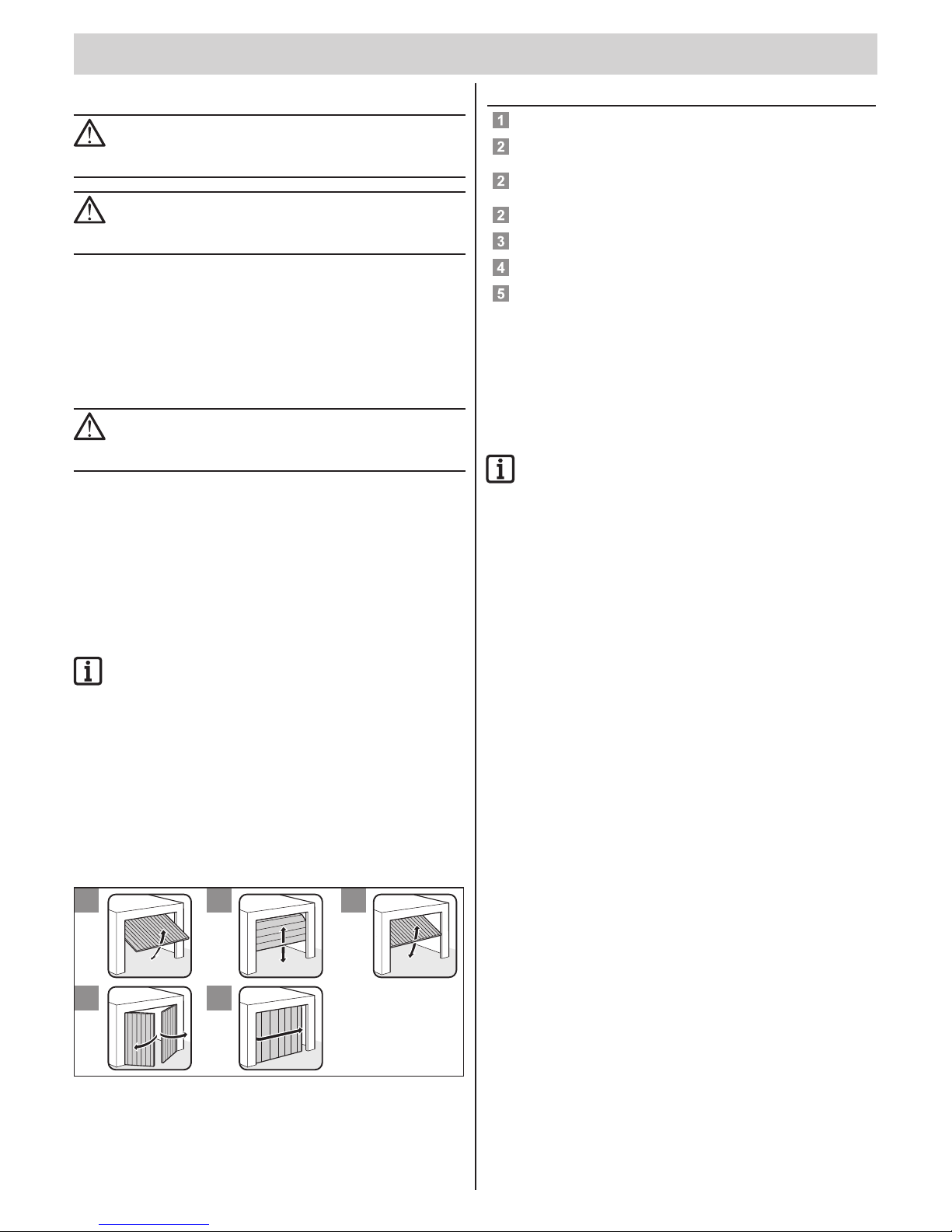
Door types and accessories*
* Accessories not included in the scope of delivery
12 3
45
No. Door type Accessories
Swinging door No accessories required
Sectional door with single
running rail
Sectional door tting with
boomerang *
Sectional door with double
running rail
Sectional door bracket without
boomerang
Sectional overhead door No accessories required
Up-and-over door Curved arm *
Hinged double door Hinged double door tting *
Roller door, side-sectional door Consult your specialist dealer
Tips for installation
• Check the delivery scope components before beginning installation;
this way you save time and unnecessary effort if a part is missing.
• With two persons, installation can be carried out quickly and safely.
• Ensure that the door does not become twisted or jammed in the running
rails.
CHECK:
Open and close the door by hand several times at the location
where the drive is to be installed. If the door can be operated
easily at this location (without exceeding the specied
forces), then the drive can be installed.
Emergency release
In a garage without a separate entrance (e.g. slip doors), the drive's
emergency release must be operable from outside. Thus, position the
emergency release so that it externally accessible; this can be done with
a Bowden cable or an emergency release lock. For this purpose, Backjump
(DIP switch 6 ON) should always be switched on. Refer to the chapter
“Functions and connections - Backjump (DIP 6)”.
Swinging doors
Because the mechanical locking of a door equipped with a drive must be
removed or disabled, depending on the design of the door, it could be
possible to manually raise the door approx. 50 mm. To counteract this,
spring catches can installed to lock the door in addition to the drive. These
spring catches are connected to the drive by means of a locking set; when
opening a door, the spring catches must rst be disengaged before the
drive can open the door.
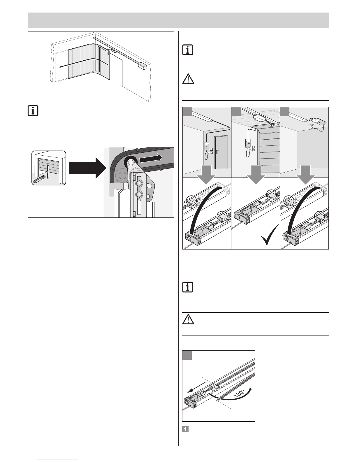
Hinged double door, roller door or side-sectional door
With drives that push one of the previously mentioned doors ahead (see
graphic below), the polarity of wires 3 + 4 must be reversed on the direct
connector. See chapter “Functions and connections - direct connector”.
Installation
Page 9
Installation
t
– 9
Additional pulse transmitters are: hand-held transmitters,
Telecody, wireless indoor switches and key switches. In the
case of the hand-held transmitter, Telecody or the wireless
indoor switches, a connecting line to the drive is not required;
consult your dealer.
Adjusting the top roll of a sectional door
Selection of installation variants
NOTE!
Select the desired installation variant.
The power supply lines must be adapted for the installation
variants (A/C)!
ATTENTION!
The chain cover is not packaging. Do not remove it!
Make sure that the chain is always completely clipped into the
chain cover and all parts of the chain cover have been pushed
together so they are ush.
V
V
CB
A
V
ok
7 7
Preinstallation of installation
variant A/C
NOTE!
Dispose of the packaging according to locally applicable
regulations.
Open the package and inspect the delivery scope.
ATTENTION!
Make sure that all components are not lying directly on a hard
surface. To protect the components, place cardboard, covers
or other soft surfaces underneath.
Remove the drive from the packaging.
1
1
2
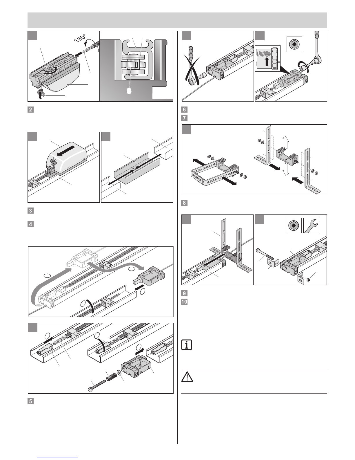
Loosen the guide idler (1) and push it in the direction of the arrow;
fold out the chain guide (2).
Page 10
Installation
t
– 10
2
N
2
1
3
2
4
33
Slide the carriage (1) onto the chain (2) with chain guide (4). The chain (2)
engages in the chain wheel (3). If the chain wheel (3) does not rotate, pull
once on the emergency release cord (N). The chain wheel (3) is then
unlocked.
3
2
1
4
1
1
2
Insert the carriage with the chain (1) into the C-rail with the guide idler
“V” (2). The tip of the guide idler “V” must point toward the carriage.
Push the two rails (1) over the connecting sleeve (2) up to the stop
position. You now have a single continuous rail. When pushing the rails
together, ensure that the chain is guided through the guide idler “H”.
The tip of the guide idler “H” must point toward the carriage (1).
C
A
B
90°
D
5
a
c
90°
b
1
2
3
4
5
6
V
V
a) Hook the tensioner (1) into the chain (2).
b) Turn the tensioner 90°.
c) Push the slide-in part (6) in the rail and insert the tensioner. Put the
washer (5) and spring (4) on the tensioning screw (3) and screw the
tensioning screw (3) into the tensioning element.
6 7
10mm
V
Don’t tighten here; pretensioned at the factory.
Tighten the chain as far as the mark (arrow).
8
Disassemble the two steel brackets (1) with washers (4) and toothed
lock washers (3) from the ceiling suspension bracket (2).
91
0
17mm 17mm
1
2
2
4
1
3
V
Push the ceiling suspension bracket (1) onto the C-rail (2).
Fasten the two headers (2) with bolt (1) and washers (3) on the slide-in
part (4), but do not completely tighten yet.
Preinstallation of installation
variant B
NOTE!
Dispose of the packaging according to locally applicable
regulations.
Open the package and inspect the delivery scope.
ATTENTION!
Make sure that all components are not lying directly on a hard
surface. To protect the components, place cardboard, covers
or other soft surfaces underneath.
Remove the drive from the packaging.
Page 11
Installation
t
– 11
1
1
2
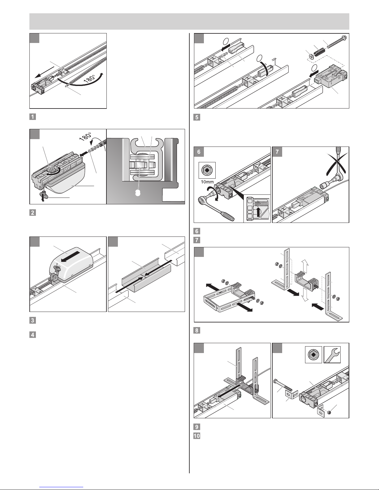
Loosen the guide idler (1) and push it in the direction of the arrow;
fold out the chain guide (2).
2
N
2
1
3
2
4
33
Slide the carriage (1) onto the chain (2) with chain guide (4). The chain (2)
engages in the chain wheel (3). If the chain wheel (3) does not rotate, pull
once on the emergency release cord (N). The chain wheel (3) is then
unlocked.
3
2
1
4
1
1
2
Insert the carriage with the chain (1) into the C-rail with the guide idler
“V” (2). The tip of the guide idler “V” must point toward the carriage.
Push the two rails (1) over the connecting sleeve (2) up to the stop
position. You now have a single continuous rail. When pushing the rails
together, ensure that the chain is guided through the guide idler “H”.
The tip of the guide idler “H” must point toward the carriage (1).
5
a
c
1
6
2
3
4
5
90°
b
a) Hook the tensioner (1) into the chain (2).
b) Turn the tensioner 90°.
c) Push the slide-in part (6) in the rail and insert the tensioner. Put the
washer (5) and spring (4) on the tensioning screw (3) and screw the
tensioning screw (3) into the tensioning element.
Tighten the chain as far as the mark (arrow).
Don’t tighten here; pretensioned at the factory.
8
Disassemble the two steel brackets (1) with washers (4) and toothed
lock washers (3) from the ceiling suspension bracket (2).
91
0
17mm 17mm
1
2
2
4
1
3
V
Push the ceiling suspension bracket (1) onto the C-rail (2).
Fasten the two headers (2) with bolt (1) and washers (3) on the slide-in
part (4), but do not completely tighten yet.
Page 12
Installation
t
– 12
Installation (example: installation
variant B)
ATTENTION!
Use a surefooted and stable ladder.
THP
THP
11
5 -
65mm
min. 35mm
THPTHP
11
5 -
65mm
min.
35mm
11
max. 30°
NOTE!
If the distance between the ceiling and the bottom edge of the
C-rail is greater than 245 mm, extend the ceiling suspension
bracket with perforated strip steel.
NOTE!
Please observe that the distance may possibly be reduced if
a door handle is attached to the middle of the door. The door
must be able to run freely.
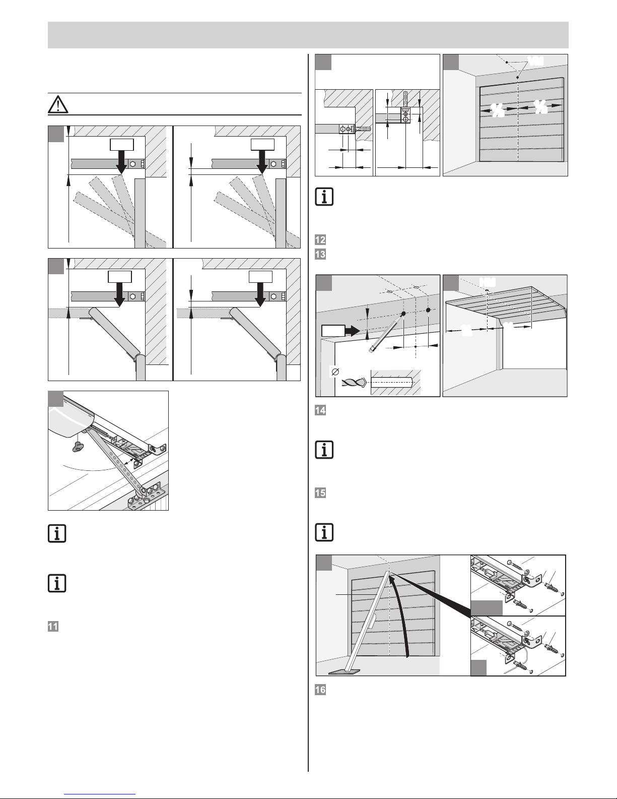
Determine the door's highest point (THP):
Open the door and measure the closest distance (min. 35 mm)
between the top edge of the door and the ceiling. The distance between
the THP and the bottom edge of the C-rail must be between 5 mm and
65 mm; the angle of the door arm must be max. 30°.
12
S
30
min.15
30
15
15
D
½½½
½
VMVM
13
NOTE!
If installing on the ceiling (D), space the drill holes 15 mm
apart if possible. Reduced tilting angle of the mounting
bracket.
The drive can be mounted on the header (S) or on the ceiling (D).
Measure the front of the center of the door (VM) and mark on the door
and header or ceiling.
15
½½½
½
HMHM
15
VM
74mm 74mm
10mm
65mm
14
THP
Make a mark 74 mm to the right and left of the center of the door (VM)
and fasten at the same height on the header or ceiling (as per picture 9).
Drill two holes (Ø 10 x 65 mm deep).
NOTE!
Wear safety glasses while drilling.
Take into account the thickness of the ceiling, especially with
regard to prefab concrete garages!
Open the door. Project the mark from the center of the door to the
ceiling (HM).
Close the door.
NOTE!
Protect the controller housing against damage.
16
2
S10
4
5
31
S10
4
5
31
B
A/C
Insert anchor ttings (1). Lift the drive (2) at the front. Tightly fasten
header tting (3) at the front with two bolts (4) and U-washers (5).
Page 13
Installation
t
– 13
ATTENTION!
Always ensure that the drive is installed parallel to the
running rails of the door.
HM
17 18
B
600
0
1
B
1
HM
3
2
5
4
S10
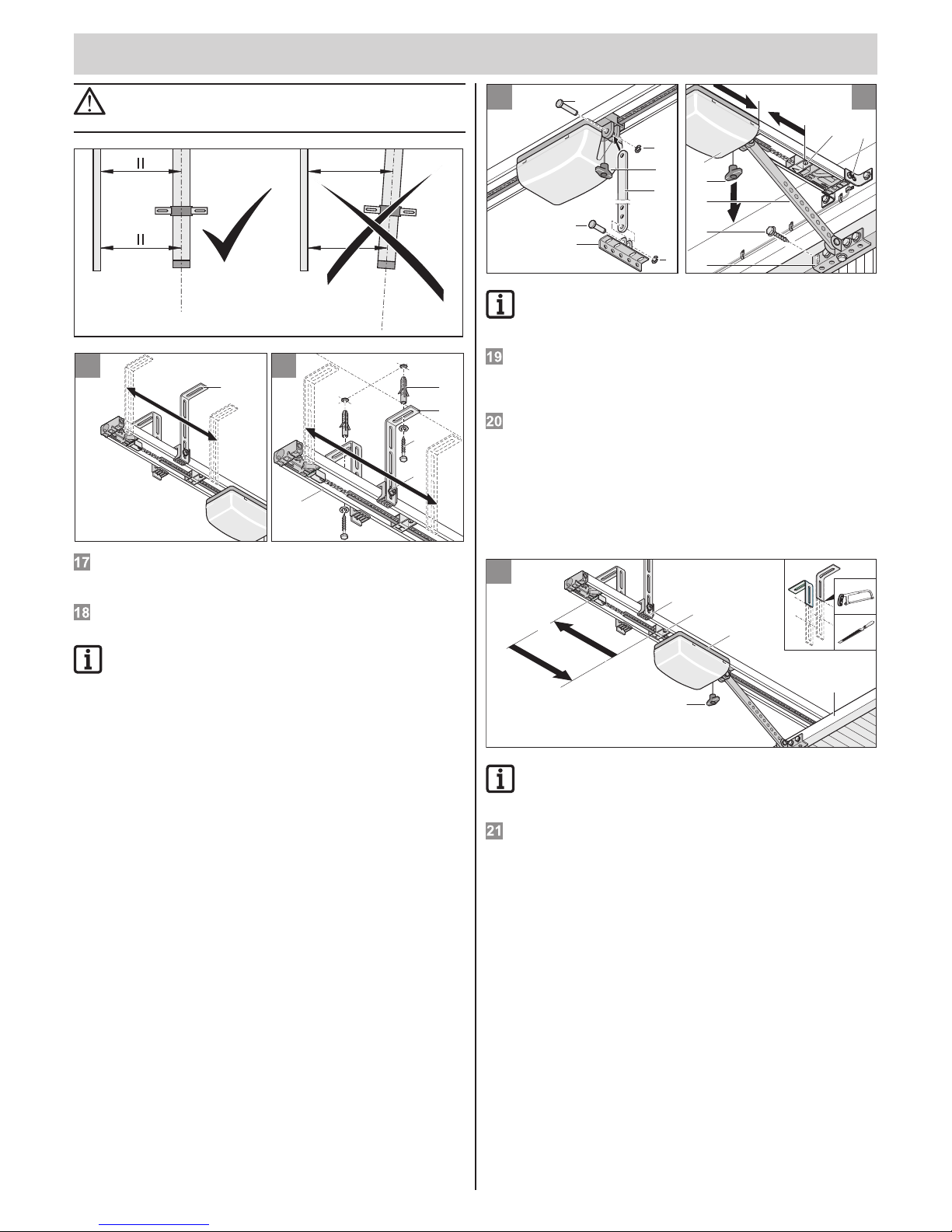
Raise the drive.
Align the ceiling suspension bracket (1). The position should be in the
range of (W = 0 …600 mm).
Align the drive horizontally to the rear of the center of the door (HM).
Mark the drill holes. Drill two holes (Ø 10 x 65 mm deep).
NOTE!
Wear safety glasses when drilling. Take the thickness of the
ceiling into consideration, especially with regard to prefab
concrete garages.
Insert anchor ttings (1). Place U-washers (3) under the two bolts (2).
Firmly tighten the bolts (2).
Vertically align C-rails (4), e.g. with a spirit level. If required by this,
reposition the bolts (5). Tighten the bolts (5).
19
2
3
5
4
3
N
1
2
48
7
3
6
5
1
N
20
NOTE!
Choose suitable bolts depending on what the door is made of.
Wear safety glasses when drilling!
Install the push rod (1):
Insert the bolts lengthwise (2) and slide on the clamp (3).
Briey fasten door bracket tting (4) to the push rod (1) with bolts (5)
and slide on the clamp (3).
Pull once on the emergency unlocking cord (N). The carriage (1) is
unlocked. Tighten the bolt (8) on the header tting.
Slide the carriage (1) all the way to the front (3) with the push rod (2).
Loosen the guide idler (4) if necessary to do this.
Align the door bracket tting (5) with the center of the door (VM) and
mark 5 drill holes. Drill 5 holes (Ø 5 mm).
Insert 5 hex bolts (6) and tighten rmly.
Loosen guide idler (4) and completely slide onto the carriage (7).
Tighten the guide idler screw (4).
21
4
N
1
2
6
4
5
3
NOTE!
Shorten the protruding ceiling suspension bracket (4), e.g. by
cutting off and deburring.
Loosen the guide idler (1) and push it completely back to the stop
position (2). Open the door (3) by hand.
Push guide idler (1) all the way up to the carriage (5). Tighten the screw
on the guide idler (1).
Page 14
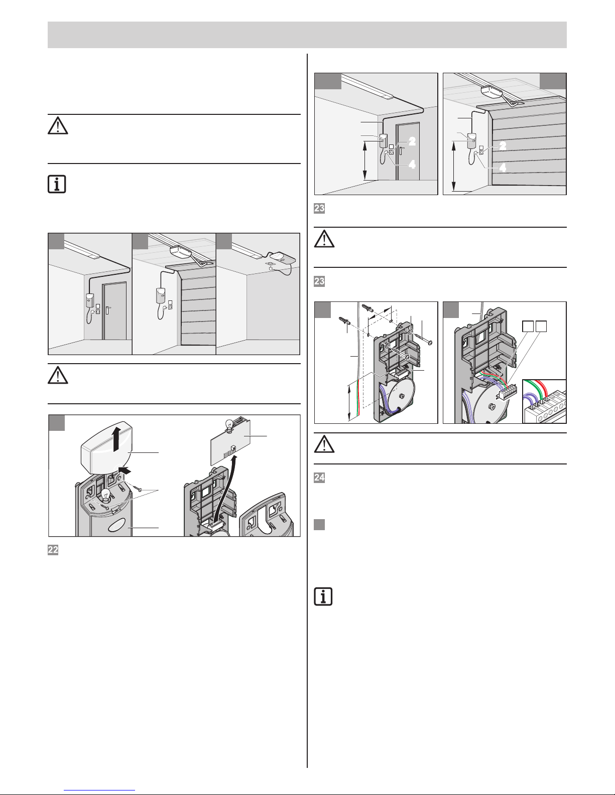
Installation
t
– 14
Mount the controller housing and
connect
Selection of the installation variant
ATTENTION!
1. Control or regulating units in a xed position must be
mounted within sight of the door. They may not, however,
be mounted close to moving parts and must be at least
1.5 m above the ground.
NOTE!
Cables should always be permanently installed. Install cables
in such a manner that it is possible to extend the power
supply lines for variant A (e.g. install with a slack loop if the
cable is to be installed at a right angle to the C-rail).
C
A
B
ATTENTION!
Danger due to electric current!
Only touch the controller (4) on the outer edge.
Don't touch the electronic components.
22
1
2
4
3
Time
Reset
Radio
LED2
LED1
Time
Reset
Radio
LED2
LED1
Reset
Radio
LED2
LED1
Reset
Radio
LED2
LED1
Take off the lamp cover (1). Unscrew the screws (2) and take off the
cover (3), remove the controller (4).
Installation variant A/B
B23
1,6m
3
1
242
4
1,6m
3
1
A23
242
4
Choose a suitable location for the controller housing (1) close to an
existing wall socket (2). The minimum height above the ground is 1.6 m.
ATTENTION!
Bear in mind the installation position of the controller
housing (1). Ensure that the maximum length of the control
cable (3) of 6900 mm is not exceeded.
Install the control cable (3) (24 V) to the controller housing (1) in the
garage. Do not plug in the power mains plug (4) yet.
24
25
2
1
2
3
4
5
6
1
2
3
4
5
6
5
34
4
95
S 6
1
2
5
6
ca 150
ATTENTION!
Do not drill into the power supply line to the wall socket!
Do not plug in the power mains plug yet.
Drill two holes (Ø 6 x 40 mm deep). Insert anchor ttings (2) into the
drill holes.
Afx the controller housing with two screws (1) and two washers (6),
align the unit properly and rmly tighten the screws.
Insert the end of the control cable (5) through the back of the controller
housing (4).
Connect the control cable (5): With hinged double doors, connect the
wire marked with 3 (green) to terminal 3 and the wire marked with 4 (red)
to terminal 4 of the direct connector (2). Shorten the control cable (5)
if necessary.
NOTE!
With hinged double doors, connect the wire marked with 3
(green) to terminal 4 and the wire marked with 4 (red) to terminal 3 of the direct connector (2).
25
Page 15
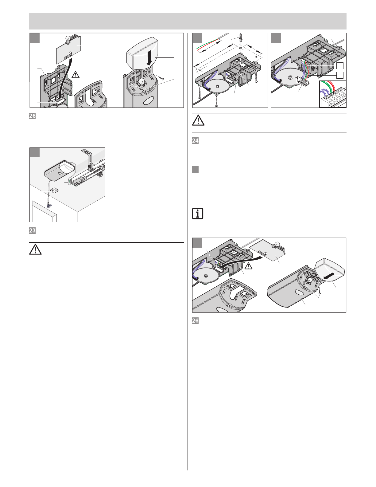
Installation
t
– 15
26
5
1
3
2
4
Time
Reset
Radio
LED2
LED1
Time
Reset
Radio
LED2
LED1
Reset
Radio
LED2
LED1
Reset
Radio
LED2
LED1
6
Put the controller circuit board (1) into the base frame (2) and insert into
the direct connector (3). Put the cover (4) in place and fasten with
screws (5). Put the lamp cover (6) in place.
Installation variant C
1
3
2
4
23
Choose a suitable location for the controller housing (1) close to an
existing wall socket (2).
ATTENTION!
Bear in mind the installation position of the controller
housing (1). Ensure that the maximum length of the control
cable (3) of 6900 mm is not exceeded.
Install the control cable (3) (24 V) to the controller housing (1) in the
garage. Do not plug in the power mains plug (4) yet.
25
2
1
2
3
4
5
6
1
2
3
4
5
6
5
3
4
4x
24
250
ca 150
2
4x
95
1
6
ATTENTION!
Do not drill into the power supply line to the wall socket!
Do not plug in the power mains plug yet.
Drill four holes (Ø 6 x 40 mm deep). Insert anchor ttings (2) into the drill
holes. Delivery scope: 2x anchor ttings, 2x screws and 2x washers.
Afx the controller housing with four screws (1) and four washers (6),
align the unit properly and rmly tighten the screws.
Insert the end of the control cable (5) through the back of the controller
housing (4).
Connect the control cable (5): With hinged double doors, connect the
wire marked with 3 (green) to terminal 3 and the wire marked with 4 (red)
to terminal 4 of the direct connector (2). Shorten the control cable (5)
if necessary.
NOTE!
With hinged double doors, connect the wire marked with
3 (green) to terminal 4 and the wire marked with 4 (red) to
terminal 3 of the direct connector (2).
26
5
1
2
3
4
Time
Reset
Radio
LED2
LED1
Time
Reset
Radio
LED2
LED1
Time
Reset
Radio
LED2
LED1
Time
Reset
Radio
LED2
LED1
6
Put the controller circuit board (1) into the base frame (2) and insert into
the direct connector (3). Put the cover (4) in place and fasten with
screws (5). Put the lamp cover (6) in place.
25
Page 16
Installation
t
– 16
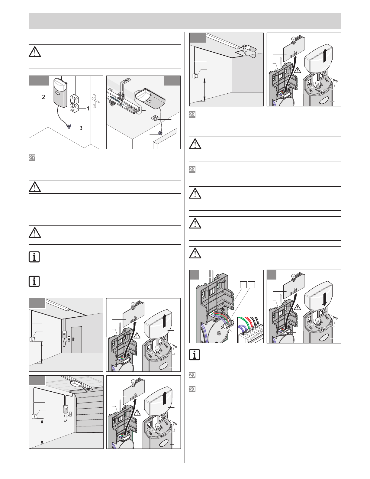
Install the wall socket.
ATTENTION!
Wall sockets may only be installed by a trained electrician.
Protect the wall socket with a circuit breaker (16 A, slow-blow).
Comply with all applicable regulations (e.g. the German VDE).
A/B 27
H
1
3
2
4
C27
Install the socket (1) on the wall at a distance of approx. 0.5 m from the
controller housing (2) for variant A/B, or on the ceiling for variant C.
Install and hook up the connecting line from the socket (1) to the
electrical power mains.
ATTENTION!
Do not plug the power mains plug (3) into the socket yet.
Install and connect the additional
button
ATTENTION!
Only use the connection for potential-free closer contacts.
External voltage can damage or destroy the controller.
NOTE!
Installation of an additional button is only necessary if an
extra one is required apart from the integrated button.
NOTE!
Never lay the cable of the key switch along a power line as
this could cause interference in the control unit.
7
6
3
4
5
Time
Reset
Radio
LED2
LED1
Time
Reset
Radio
LED2
LED1
1,6m
A28
2
1
7
6
3
4
5
Time
Reset
Radio
LED2
LED1
Time
Reset
Radio
LED2
LED1
B28
1,6m
2
1
7
6
3
4
5
Time
Reset
Radio
LED2
LED1
Time
Reset
Radio
LED2
LED1
1,6m
2
1
C28
Install the key switch (1) in a suitable, easily accessible position in the
garage. Minimum height above the ground: 1.6 m.
Install the switch cable (2) in the garage. Connect the end of the cable
to the button (1).
ATTENTION!
Danger due to electric current!
Only touch the controller (4) on the outer edge.
Don't touch the electronic components.
Take off the lamp cover (3). Unscrew the screws (4) and take off the
cover (5). Upwardly pull the controller circuit board (1) out of the base
frame (6).
ATTENTION!
After installation, it is imperative that you check the drive to
ensure that it has been correctly adjusted and that it reverses
upon contacting a 50 mm high object on the oor.
ATTENTION!
After installation, it is imperative to check whether the drive
stops when it encounters a 20 kg load that attached to the
middle of the bottom edge of door.
ATTENTION!
After installation, ensure that no parts of the door protrude
into public sidewalks or streets.
3029
4
1
2
3
4
5
6
1
2
3
4
5
6
3
56
1
3
2
6
5
4
Time
Reset
Radio
LED2
LED1
Time
Reset
Radio
LED2
LED1
NOTE!
Connect any key switches (potential-free NO contact) that are
present in parallel to terminals 5 + 6.
Connect the switch cable (3) to terminals 5 + 6 on the direct
connector (4).
Put the controller circuit board (1) into the base frame (2) and insert into
the direct connector (3). Put the cover (4) in place and fasten with
screws (5). Put the lamp cover (6) in place.
Page 17
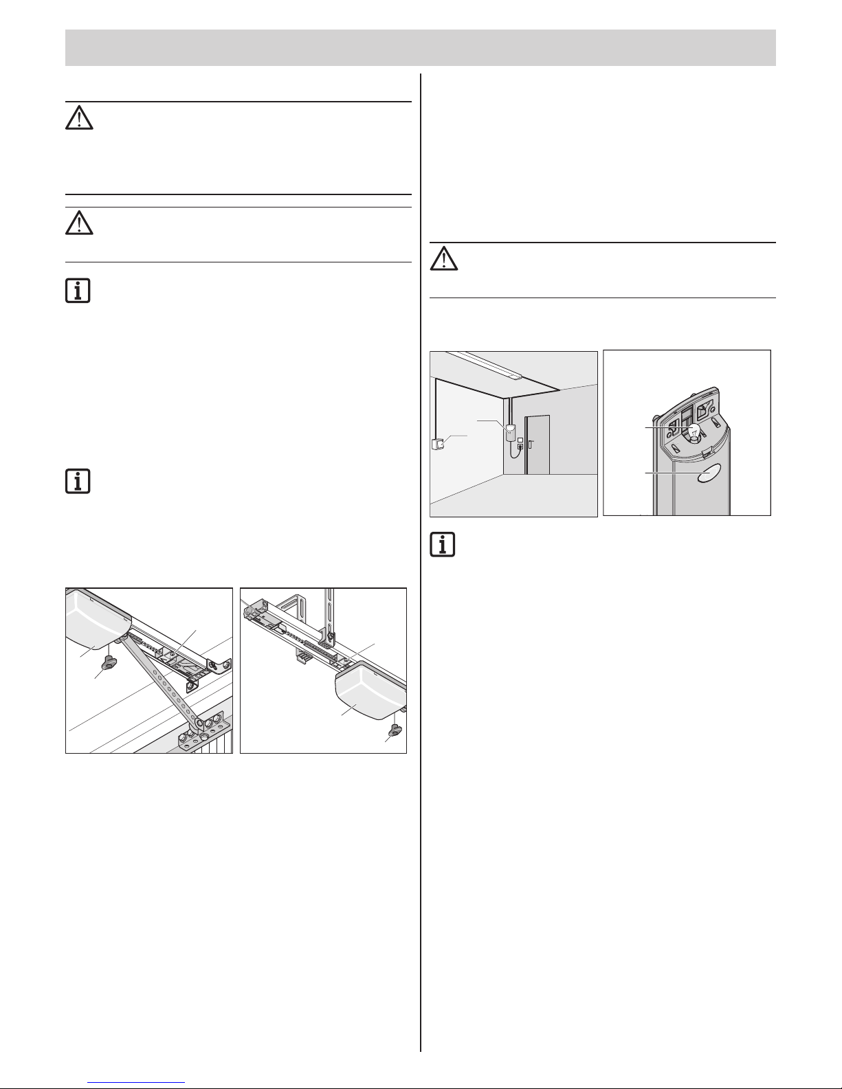
– 17
t
Safety instructions
RISK OF INJURY!
The force setting is relevant to safety and must be carried
out by trained specialists with the utmost caution. If the force
tolerance is too high, persons or animals could be injured and
objects damaged.
Select the force tolerance to be as low as possible to ensure
that obstacles are detected quickly and safely.
DANGER OF FALLING!
Actuating the emergency release can lead to uncontrolled
door movements if springs are weakened or broken, or if the
door has not been optimally weight-balanced.
NOTE!
After installation of the drive, the person responsible for the
installation must complete an EC declaration of conformity for
the door system in accordance with the Machinery Directive
2006/42/EC, and apply the CE mark and a type plate.
This is also required for private installations, including if
the drive is retrotted to a manually-operated door. This
documentation and the Installation and Operating Instructions
are retained by the operator.
Adjust door end positions for
CLOSE + OPEN
NOTE!
Only open or close the door by hand during while adjusting;
do not use the engaged drive.
The running path of the drive can be extended or shortened (V + H)
by means of the guide idlers.
Check whether the door opens and closes completely. If this isn't the case,
then the running path and/or the limit stops must be adjusted.
V
N
1
H
1
N
Door end position CLOSED
1. Unlock the carriage. Pull once on the emergency unlocking cord (N).
It should be possible to manually push the carriage back and forth.
2. Close the door by hand.
3. Loosen the guide idler (V) and push it toward the carriage until it clicks.
⇒ Limit switch switches.
4. Tightly fasten the guide idler (V).
Door end position OPEN
1. Open the door by hand.
2. Loosen the guide idler (H) and push it toward the carriage until it clicks.
⇒ Limit switch switches.
3. Tightly fasten the guide idler (H).
4. Close the door by hand.
Lock the carriage (1).
1. Pull once on the emergency unlocking cord (N).
2. Manually push the carriage a bit until the chain wheel makes an audible
click.
⇒ The chain wheel makes a loud click sound when it snaps into place.
Programming the drive
The control system has an automatic force setting. The control system
automatically records the force required during the “OPEN” and “CLOSE”
door movements and stores it when the end positions have been reached.
ATTENTION!
Before sticking in the power mains plug, ensure that the
voltage of the power source corresponds with the voltage
listed on the drive type plate.
1. Stick in the power mains plug.
⇒ The lamp (2) blinks.
2
1
Ti
me
Rese
t
Radio
LE
D
2
LED1
Time
Reset
Radi
o
LED2
LED1
1
1
NOTE!
The rst movement of the drive after switching on the mains
power must always be door OPEN. If this isn't the case, then
reverse the cables at terminals 3 + 4.
2. Press button (1).
⇒ The door opens to the until the door OPEN end position is reached.
3. Press the button (1).
⇒ The door closes until the door CLOSED end position is reached.
4. Reset the controller. Controller reset according to drive type:
see chapter “Operation/use - controller reset”
Perform the following procedure twice:
1. Press button (1) once.
⇒ Door opens to guide idler (H, door OPEN).
⇒ The lamp (2) blinks.
2. Press button (1) once.
⇒ Door closes to guide idler (V, door CLOSED).
⇒ The lamp (2) blinks.
3. If the lamp (2) lights up, the force values have been recorded and stored.
⇒ The drive has been successfully programmed.
Check door end positions OPEN + CLOSED
The running path of the drive can be extended or shortened by means of
the guide idlers.
Check whether the door opens and closes completely. If this isn't the case,
then the running path must be adjusted.
Initial operation
Page 18
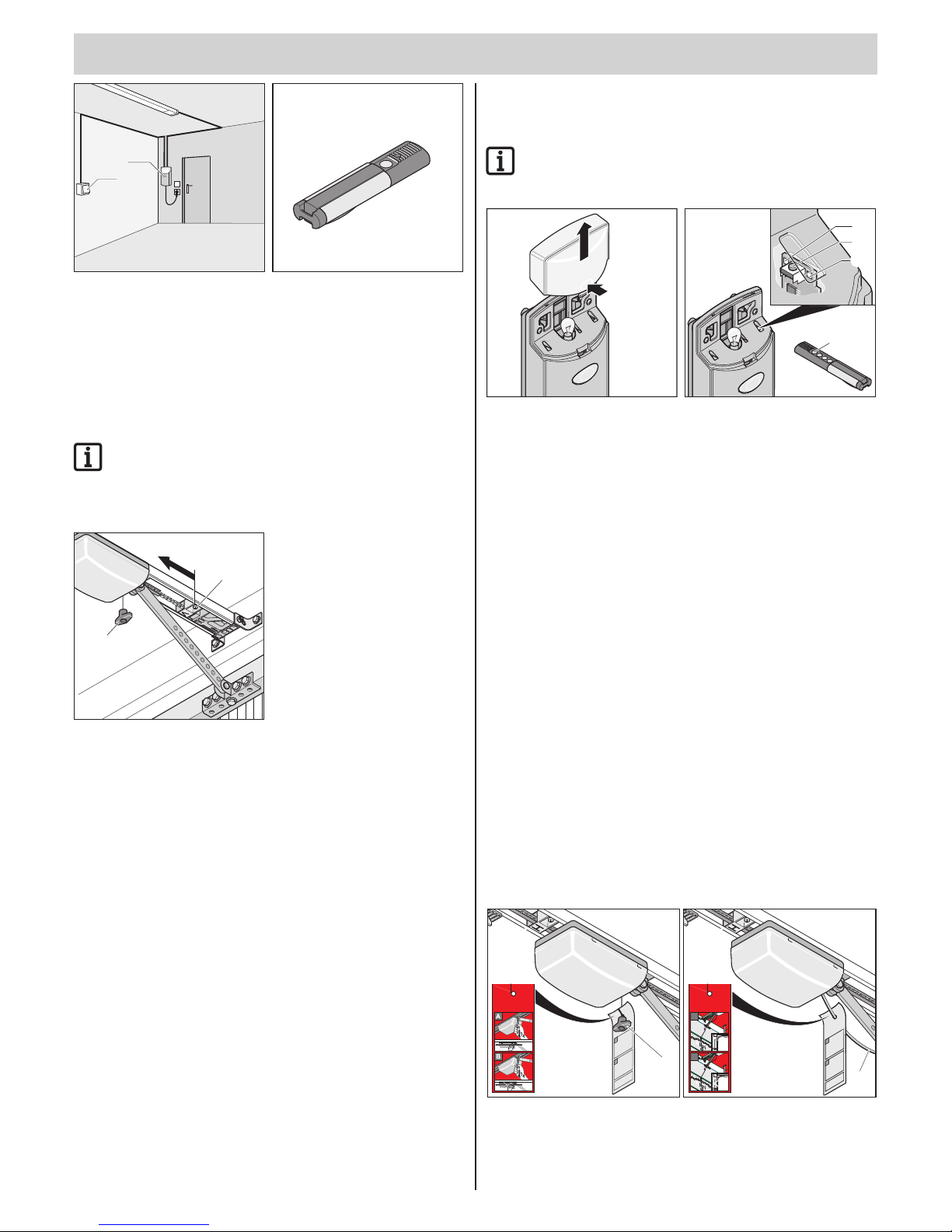
Initial operation
t
– 18
1
2
1. Voltage uctuations e.g.: Actuate control device (e.g. button, hand-held
transmitter, etc.) once.
⇒ The door opens to the until the door OPEN end position is reached.
2. Check whether the door reaches the desired end positions.
⇒ Adjust the end positions if necessary. See the chapter
“Commissioning - adjusting the door Closed + Open end positions”.
Checking the emergency release
NOTE!
You can activate Backjump for sectional doors or doors
with ceiling guides by means of DIP switch 6; this relieves
the drive and door mechanisms. Simpler actuation of the
emergency release.
V
N
1
1. Close the door with the drive.
2. Pull once on the emergency release (N).
If the emergency release cannot be actuated, loosen the end switch (V)
and push it a bit in direction (1).
3. Open and close the door with the drive. Recheck the emergency release.
Check the force settings
For every run of the door, the controller compares the stored force values
with the actual values required and automatically adjusts the stored values
upon reaching the end position.
Check: See chapter “Care and maintenance / regular testing”.
Programming the hand-held
remote control
NOTE!
Before programming the hand-held transmitter for the rst
time, always clear the radio receiver memory completely.
Time
Reset
Radio
LED2
LED1
Time
Reset
Radio
LED2
LED1
5
Time
Reset
Radio
LED2
LED1
Time
Reset
Radio
LED2
LED1
adio
LED2
LED1
adio
LED2
LED1
3.2
1
3.1
Deleting the radio receiver memory
1. Take off the lamp cover.
2. Press and hold the Learn button (1).
⇒ After 5 seconds, the LED ashes (3.1 or 3.2).
⇒ After another 10 seconds, the LED lights up steadily (3.1 or 3.2).
⇒ After a total of 25 seconds, all LEDs light up steadily (3.1 and 3.2).
3. Release the Learn button (1) - the deletion procedure is ended.
Programming the hand-held remote control
1. Press the Learn button (1).
▫ 1x for channel 1; the LED (3.1) lights up.
▫ 2x for channel 2; the LED (3.2) lights up.
⇒ If no code is sent within 10 seconds, the radio receiver switches to
Normal mode.
2. Press the desire hand-held transmitter button (5) until the LED (3.1/3.2)
extinguishes, depending upon which channel has been selected.
⇒ LED extinguishes - programming is nished.
⇒ The hand-held transmitter has transferred the radio code to the
radio transmitter.
3. For the additional programming of hand-held transmitters, repeat the
steps above. A maximum of 112 memory locations are available for
each radio receiver.
Canceling the Learn mode:
Press the Learn button (1) until no more LEDs are lit.
Mount the information sign
N
N
46502V000-172006-0-OCE_Rev.A
1x1x
1x1x
46502V000-172006-0-OCE_Rev.A
A
B
The information sign concerning the function of the emergency release;
please hang on the emergency release cord.
Page 19
Initial operation
t
– 19
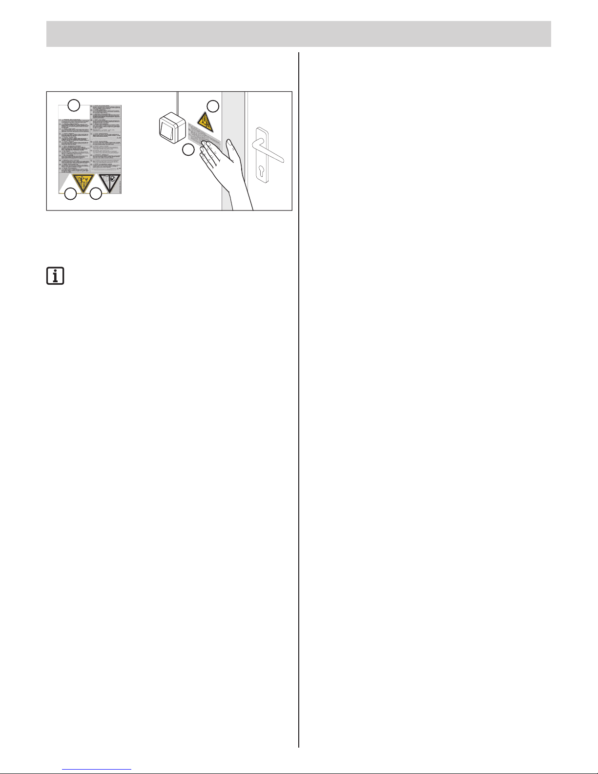
Attaching the warning sign
i
1.
2.
2.
1.
3.
Attach the warning signs (text + triangle sign) at a position where they are
clearly visible, e.g. beside the pushbutton (warning triangle) and on the
door wing (text + warning triangle).
NOTE!
See page 26 “Cleaning chains and drive unit rail”.
Place the sticker on a clearly visible location near the running rail.
Page 20
– 20
t
Safety instructions
¾ Continuously monitor the door while it is in motion and keep all persons
away from it until the door is completely opened or closed.
¾ Never put your hand near the door when it is moving or near moving
parts.
¾ Only pass through the door only once it is completely open.
¾ There is a risk of persons being crushed or cut by the mechanism or
sharp edges of the door.
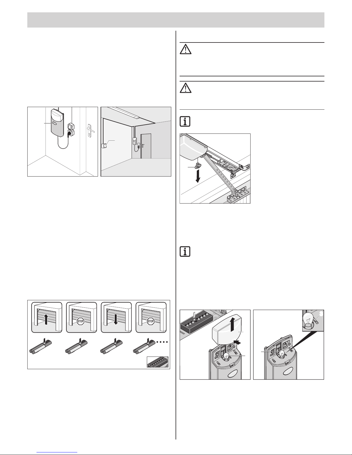
Open door
1
1
1. Press button (1) or hand-held transmitter button once to open the door.
2. Press the button (1) again for the door movement “OPEN”.
⇒ The door stays in place (depending on DIP switch 7).
3. If the door has stopped, press the button (1) again.
⇒ The door closes (depending on DIP switch 7).
Close door
1. Press button (1) or hand-held transmitter button to close the door.
2. Press the button (1) again for the door movement “CLOSE”.
⇒ The door stays in place (depending on DIP switch 7).
3. If the door has stopped, press the button (1) again.
⇒ The door opens (depending on DIP switch 7).
Pulse sequence of door movement
Set pulse sequence with DIP switch 7.
2
1
ON
DIP
3
4
5
6
8
7
1x
1x
1x
1x
STOP STOP
DIP 7 OFF, standard setting for all drives
(see diagram):
• Open - Stop - Close - Stop - Open …
DIP 7 ON:
• Button 1: Open - Stop - Open - Stop - …
• Button 2: Close - Stop - Close - Stop - …
Emergency release
ATTENTION!
The emergency release is only suitable for opening or closing
the door in case of an emergency, e.g. a power outage or
drive failure. E.g. a power outage or drive failure. It is not
suitable for regularly opening or closing the door for other
reasons. This could cause damage to the drive or door.
DANGER OF FALLING!
In case of an emergency release, the door could
independently open or close itself due to a broken spring or
incorrect setting of the weight balancing. The drive could be
damaged or destroyed.
NOTE!
It can be locked and released in any door position.
N
1. Pull once on the emergency unlocking cord (N).
⇒ The drive moves freely and the door can be moved manually.
2. Pull on the emergency unlocking cord (N) again.
⇒ The drive clicks into place and the door can only be moved
mechanically.
NOTE!
If there is a slip door installed in the door, but no slip door
safeguard, install slip door safeguard (see accessories
instructions).
If the garage door does not have a built-in slip door or the
garage does not have a separate entrance, you must install an
emergency release - a release lock or Bowden cable - that can
be operated from outside (see accessories instructions).
Control unit reset
2
1
Time
Reset
Radi
o
LED2
LE
D
1
Time
Reset
Radi
o
LED
2
LE
D1
2
Ti
me
Rese
t
Radio
LE
D
2
LE
D1
Time
Reset
Radi
o
LED2
LED1
Rese
t
R
eset
33
2
1
ON
DI
P
3
4
5
6
8
7
1. Take off the lamp cover (1).
2. Press button (3) until the light bulb (2) goes out.
⇒ Light bulb (2) off - force values deleted.
3. Release the button (3).
⇒ Light bulb (2) blinks and controller reset has been successfully
performed.
Operation / Use
Page 21
Operation / Use
t
– 21
The light bulb behaves differently depending on the DIP switch:
• DIP switch 4 ON,
light bulb (2) lights up after the controller reset.
• DIP switch 4 OFF,
light bulb (2) blinks after the controller reset.
NOTE!
After a controller reset, the drive must be reprogrammed.
Intermediate stop
An intermediate stop, caused by actuating a button or hand-held remote
control, immediately stops the drive. At the next command the drive moves
in the opposite direction; see chapter “Operation/use - pulse sequence of
door movement”.
Safety stop 1
(power cut-off)
For a power cut-off, the drive stops or reverses. At the next command the
drive moves in the opposite direction; see chapter “Operation/use - pulse
sequence of door movement”.
• Safety stop when closing the door: the door reverses.
• Safety stop when opening the door: the door stops.
Safety stop 2
(safety input)
When the safety input is triggered (e.g. if someone has gone across the
photo eyes), the drive stops, reverses or opens depending on the setting of
the DIP switches.
Explanations of and setting options for the DIP switches can be found in the
chapter “Functions and connections - obstacle detection”.
Factory settings: DIP switches 1 and 3 OFF:
• Door reverses if safety input is triggered while the door is closing.
• If the safety input is activated while the door is opening, there is no
reaction (the door continues to open).
Overload protection
If the drive is overloaded during opening or closing, the control system
detects it and stops the drive. After about 20 seconds or a control system
reset, the control system releases the overload protection again.
The drive can now resume operation.
Operation after a power failure
The programmed force values are retained in the event of a power failure.
The rst movement of the drive after a power failure is always door OPEN.
Radio receiver
HOMELINK-COMPATIBLE!
If your vehicle is equipped with a HomeLink system
(Version 7), our drive and radio receiver with 868.6 MHz are
compatible. Another radio frequency (40.685 or 434.42 MHz)
must be used with older HomeLink systems. For information
see: “http://www.eurohomelink.com”
Safety instructions
¾ The local safety regulations for the system must be complied with to
ensure safe operation. Information is available from electric power
providers, industry associations (such as the German VDE) and
employers' liability insurance providers.
¾ The operator is not protected against interference caused by other
telecommunications equipment or devices (e.g. wireless systems which
are being operated properly in the same frequency range).
¾ Replace the hand-held transmitter unit's batteries if you experience
reception problems.
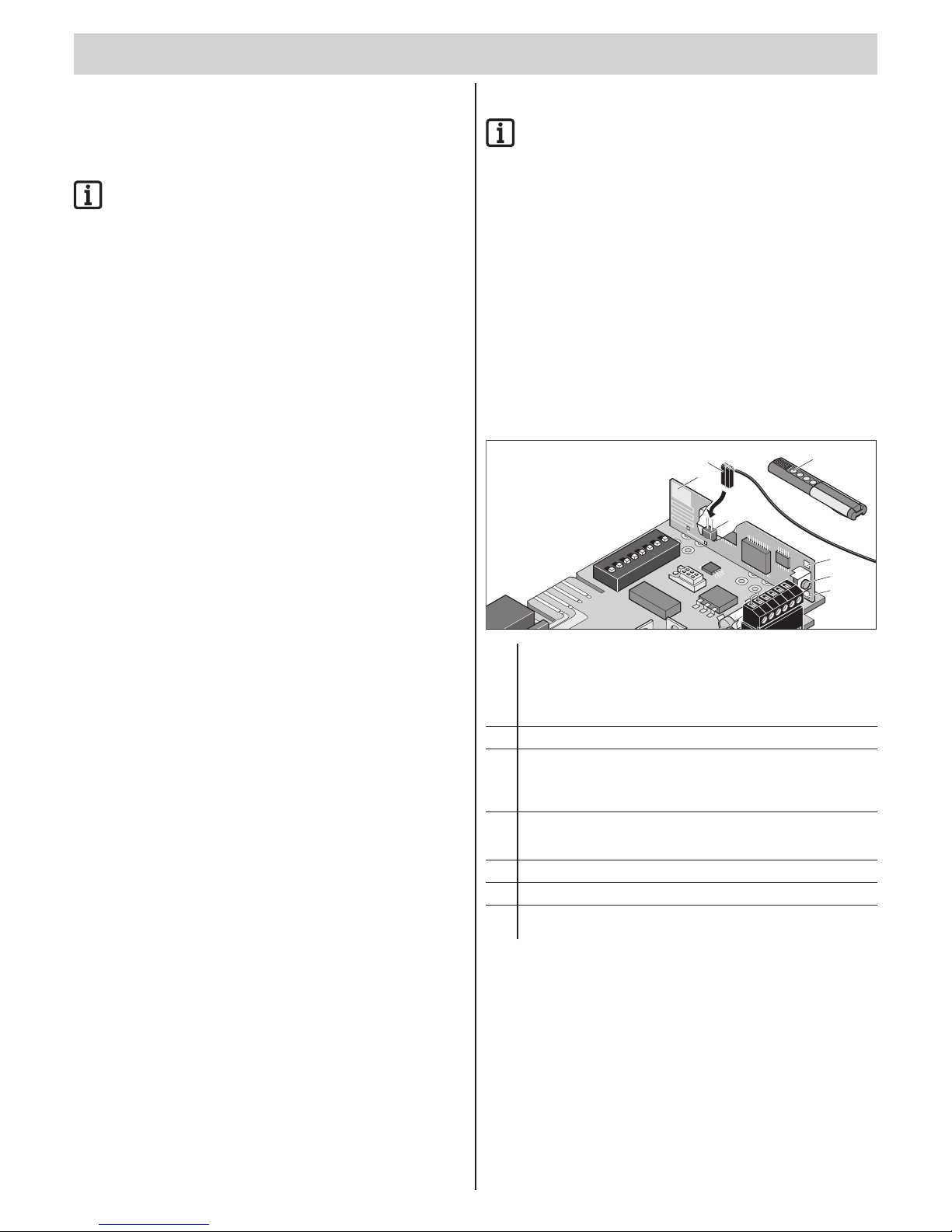
Display and button explanation
5
2
6
4
3.1
3.2
1
2
1
ON
DI
P
3
4
5
6
87
8
9
10
11
12
7
1
Learn button - sets the radio receiver in different operating modes:
• Learn mode
• Delete mode
• Normal mode
2
Internal antenna
3
LEDs - show which channel has been selected.
• 3.1 LED channel 1
• 3.2 LED channel 2
4
Connection for an external antenna
An external antenna (6) can be used if the range with the internal
antenna is insufcient.
5
Hand-held transmitter button
6
External antenna
7
Optional: an external radio receiver can be connected in the
housing (special accessory)
Page 22

Operation / Use
t
– 22
Programming the hand-held remote control
1. Press the Learn button (1).
▫ 1x for channel 1; the LED (3.1) lights up.
▫ 2x for channel 2; the LED (3.2) lights up.
⇒ If no code is sent within 10 seconds, the radio receiver switches to
Normal mode.
2. Press the desire hand-held transmitter button (5) until the LED (3.1/3.2)
extinguishes, depending upon which channel has been selected.
⇒ LED extinguishes - programming is nished.
⇒ The hand-held transmitter has transferred the radio code to the
radio transmitter.
3. For the additional programming of hand-held transmitters, repeat the
steps above. A maximum of 112 memory locations are available for
each radio receiver.
Canceling the Learn mode:
Press the Learn button (1) until no more LEDs are lit.
Deleting a hand-held remote control button
from the radio receiver
If a user moves to a group garage unit and wishes to use the hand-held
transmitter with it, all radio codes in the transmitter must be deleted from
the radio receiver.
For safety reasons every button and all button combinations must be
deleted from the hand-held transmitter.
1. Press the Learn button (1) and keep it pressed for ve seconds.
⇒ An LED blinks (which one is irrelevant).
2. Release the Learn button (1).
⇒ The radio receiver is in Deletion mode.
3. Press the hand-held transmitter button whose code should be deleted
in the radio receiver.
⇒ The LED extinguishes. The deletion procedure is ended.
4. Repeat the procedure for all buttons and button shortcuts.
Deleting a channel from the radio receiver
1. Press and hold the Learn button (1).
▫ 1x for channel 1; the LED (3.1) lights up.
▫ 2x for channel 2; the LED (3.2) lights up.
⇒ After 5 seconds, the LED ashes (3.1 or 3.2).
⇒ After another 10 seconds, the LED lights up steadily (3.1 or 3.2).
2. Release the Learn button (1).
⇒ The deletion procedure is ended.
Deleting the radio receiver memory
If a hand-held transmitter is lost, all channels in the radio receiver must be
deleted for security reasons. Afterward, the radio receivers of all hand-held
remote control must be reprogrammed.
1. Press and hold the Learn button (1).
⇒ After 5 seconds, the LED ashes (3.1 or 3.2).
⇒ After another 10 seconds, the LED lights up steadily (3.1 or 3.2).
⇒ After a total of 25 seconds, all LEDs light up steadily (3.1 and 3.2).
2. Release the Learn button (1) - the deletion procedure is ended.
Connecting external antenna
If reception is inadequate with the radio receiver internal antenna,
an external antenna can be connected; see chapter “Functions and
connections - connecting an external antenna”.
The antenna cable may not exert any mechanical force on the radio
receiver; provide for stress relief.
What is button 2 for?
Button 2 is dened for opening and closing the door by means of two
different buttons or channels (2-channel operation). This way the door can
be opened with one button and closed with the other.
If this function is utilized, 2 buttons can be connected. For details on
settings, see chapter “Functions and connections - connecting button 2”
and chapter “Functions and connections - dened opening and closing
(DIP 7)” as well as “Partial opening (DIP 8)”.
Page 23
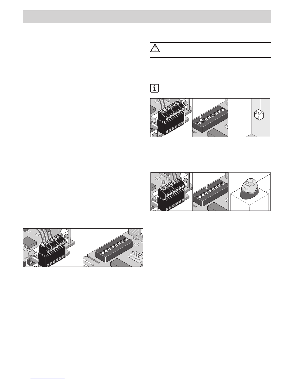
– 23
t
General information
¾ As delivered, DIP switches are set to the “OFF” position, all additional
functions are switched off.
¾ Cable length max. 10 m (at the terminal): 9 + 10, 11 + 12
¾ Cable length max. 30 m (at the terminal): 5 + 6, 7 + 8
Obstacle detection (DIP 1, 2 + 3)
Drive behavior when opening the door
If the door encounters an obstacle (power cut-off) or a safety input is
interrupted (e.g. someone passes through the photo eye), the drive detects
this and reacts according to the setting of DIP switch 1.
DIP switch 1
OFF No reaction during an interruption of a safety input. The door
stops during a power cut-off.
ON The drive stops the door.
Drive behavior when closing the door
If the door encounters an obstacle (power cut-off) or a safety input is
interrupted (e.g. someone passes through the photo eye), the drive detects
this and reacts according to the setting of DIP switches 2 + 3.
DIP switch 2: Function: safety connection
OFF NC contact for photo eye.
ON Button connection for button 2
(partial opening, dened opening and closing).
DIP switch 3: behavior of drive when the door closes.
OFF Drive stops and opens the gate slightly, reversion.
ON The drive stops and opens the door completely.
Connecting photo eyes
¾ Permissible cable gauge: max. 0.75 mm².
8
9
10 11
12
7
2
1
ON
DIP
3
4
5
6
8
7
Terminals 7 + 8 Safety connection, only if DIP switch 2 “OFF”.
Terminals 9 + 10 Regulated DC 24 V, max. 0.1 A
• Terminal 9: DC 24 V
• Terminal 10: ground
Settings: Refer to the chapter “Functions and connections - obstacle
detection (DIP 1, 2 + 3)”
Connect button 2 (DIP 2)
¾ Permissible cable gauge: max. 0.75 mm².
ATTENTION!
Only use the connection for potential-free closer contacts.
External voltage can damage or destroy the controller.
Button 2 can be used as needed for the following functions:
• Dened opening and closing
• Partial opening
ALWAYS OBSERVE!
If button 2 is used, a safety connection is no longer available.
8
9
10 11
12
7
2
1
ON
DIP
3
4
5
6
8
7
Terminals 7 + 8 Connection for button 2 only if DIP switch 2 ON
Connect warning light (DIP 4)
¾ Permissible cable gauge: max. 0.75 mm².
8
9
10 11
12
7
2
1
ON
DIP
3
4
5
6
8
7
Terminals 11 + 12 Unregulated DC 24 V (max. 34 V), max. 1 A
DIP switch 4
OFF
Connected warning light is blinking (controller generates blinking).
ON Door status display
• Lights up if the door is not closed
• Is off if the door is closed
Functions and connections
Page 24
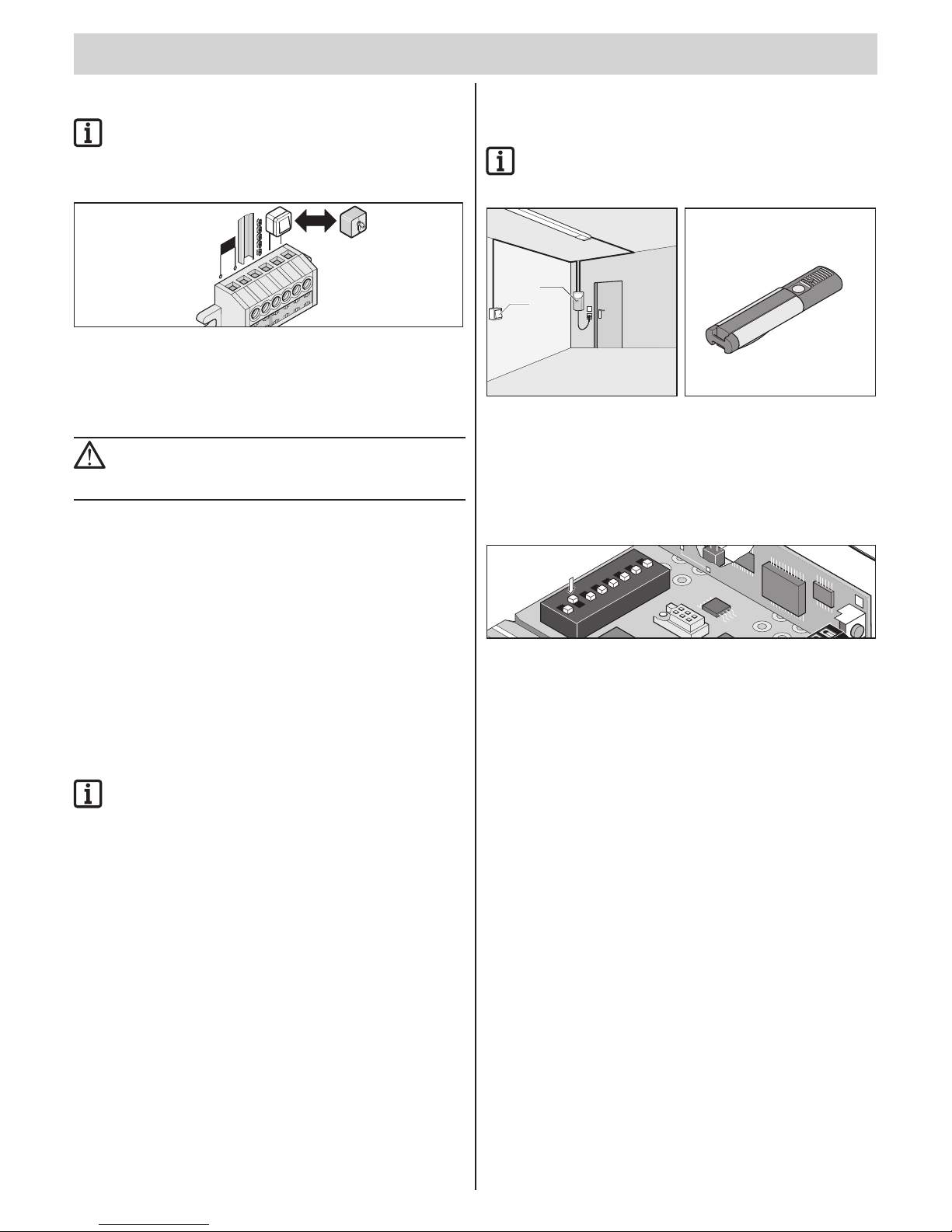
Functions and connections
t
– 24
Direct connector (button 1)
NOTE!
Reverse the connections (terminals 3 + 4) when using the
drive for a hinged double door.
¾ Permissible cable gauge: max. 1.5 mm².
2
3
4 5
6
1
Terminals 1 + 2 Transformer
Terminal 3 C-rail
Terminal 4 Chain
Terminals 5 + 6 Button connection (button 1)
ATTENTION!
Only use the connection (terminals 5 + 6) for potential-free
closer contacts. External voltage can damage or destroy the
controller.
Prewarning time (DIP 5)
Before the drive starts, a warning light blinks for 3 seconds after the button
or the hand-held transmitter is pressed. The prewarning time is cancelled
if the button or hand-held remote control is actuated again within this
timeframe.
The prewarning time affects both the internal illumination and a connected
warning light.
DIP switch 5
OFF Deactivated
ON Activated, internal lighting and warning light blink for 3 seconds.
Backjump (DIP 6)
NOTE!
You can set DIP switch 6 to ON for sectional doors or
doors with ceiling guides; this relieves the drive and door
mechanisms. Simpler actuation of the emergency release.
Serves to relieve the door and drive mechanical system. After reaching the
door CLOSE end position, the drive moves in the direction of door OPEN,
relieving the mechanical system.
DIP switch 6
OFF Deactivated
ON Activated
Dened opening and closing
(DIP 7)
NOTE!
With this function, only button 1/radio channel 1 opens the
door and button 2/radio channel 2 closes the door.
1
2
Button 1/channel 1 opens and button 2/channel 2 closes the door.
This function can also be used with only 2 buttons or just with hand-held
remote controls.
Requirement:
• DIP switch 8 “OFF”
• 2 buttons connected (DIP switch 2 ON) or 2 hand-held transmitter
buttons programmed.
2
1
ON
DIP
3
4
5
6
8
7
DIP switch 7
OFF Deactivated
ON Activated
Page 25
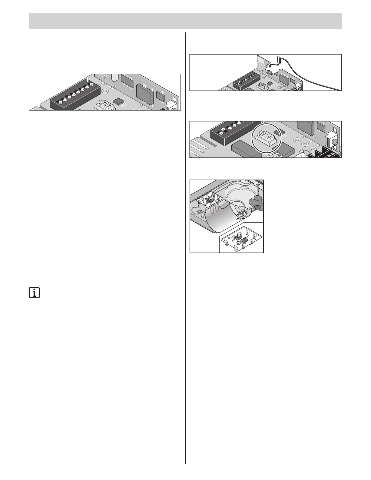
Functions and connections
t
– 25
Partial opening (DIP 8)
Depending on the setting, this function partially opens the door.
Use examples: airing out the garage, opening the side-sectional door for
personal access, and many others. The partial opening can be used with
two buttons or with hand-held transmitters.
2
1
ON
3
4
5
6
8
7
DIP switch 8
OFF Deactivated
ON Activated, DIP switch 7 non-functional
Partial opening with 2 buttons
Install additional button and connect to terminals 7 + 8 as button 2. Refer to
the chapter “Functions and connections - connecting button 2 (DIP 2)”.
• Button 1 always opens the door completely.
If the door is partially opened with button 2, pressing button 1 opens the
door completely.
• Button 2 opens the gate partially only if the gate is closed.
If the gate has been completely opened with button 1 or partially
opened with button 2, pressing button 2 again closes the gate.
Procedure
1. Close door.
2. DIP switch 8 ON activates partial opening.
⇒ Always leave DIP switch 8 set to ON, the OFF setting immediately
deletes the set partial opening.
3. Press button 2 (open door from CLOSED end position).
⇒ Door opens until button 2 is pressed again or the door reaches the
“door OPEN” end position.
4. Press button 2 once the desired position is reached.
5. Close door with button 2.
Partial opening saved and pressing button 2 opens the gate
to the saved position. Set DIP switch 8 to OFF to delete the
partial opening setting.
Partial opening with the hand-held remote control
(2-channel operation)
Programming the 2 buttons of the remote control, e.g. button 1 on radio
channel 1 and button 2 on radio channel 2.
• Radio channel 1 always has the same function as button 1.
• Radio channel 2 always has the same function as button 2.
Connecting external antenna
As-delivered status: unassigned
2
1
O
N
DIP
3
4
5
6
8
7
TorMinal interface
See TorMinal owner’s manual.
2
1
ON
3
4
5
6
7
Carriage circuit board
5
2
1
4
6
7
8
3
Terminal 1 Chain current draw
Terminal 2 Rail current draw
Terminal 3 + 4 Door OPEN end switch
Terminal 5 Motor cable
Terminal 6 Motor cable
Terminal 7 + 8 Door CLOSE end switch
Page 26
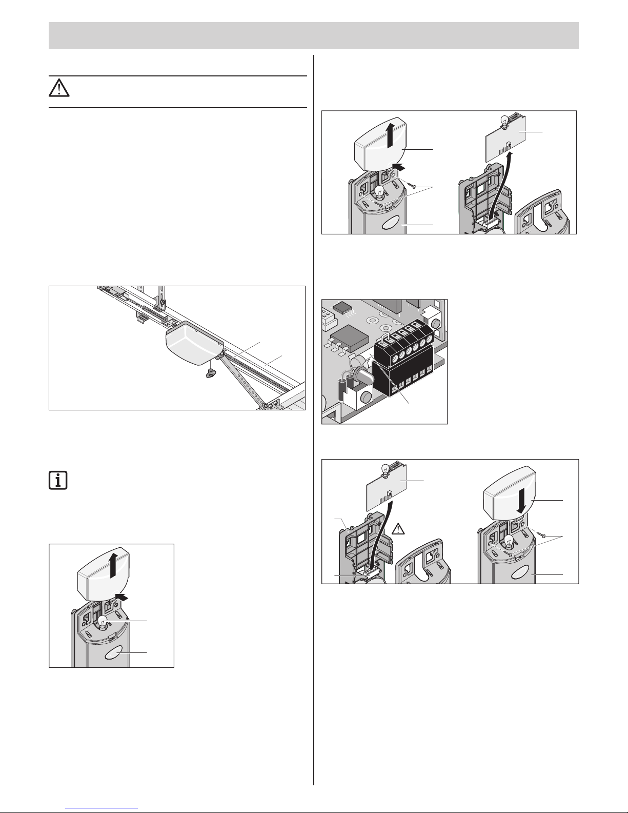
– 26
t
General information
DANGER!
Never use a hose or high-pressure cleaner to spray down the
drive or the controller housing.
¾ Always disconnect the mains plug prior to working on the drive
mechanism.
¾ Do not use acids or alkalis for cleaning.
¾ Wipe drive clean with a dry cloth as required.
¾ Never put your hand near the door when it is moving or near moving
parts.
¾ There is a risk of persons being crushed or cut by the mechanism or
sharp edges of the door.
¾ Check the mounting screws and bolts of the drive for tightness and
tighten if necessary.
¾ Check the door according to the manufacturer's manual.
Cleaning chains and drive unit rail
7
8
1. Chain (7) or the drive unit rail (8) is very dirty - cleanse it with a clean
cloth.
2. If necessary, lubricate the chain (7) and drive unit rail (8) with a
“conductive” oil. Do not use any grease!
NOTE!
Specied types of oil: Ballistol, WD40 contact spray
Replacing light bulbs
1. Unplug the mains plug from the socket.
2
1
Time
Reset
Radio
LED2
LED1
Time
Reset
Radio
LED2
LED1
2. Take off the lamp cover (1).
3. Unscrew the light bulb (2) by turning it counterclockwise and removing it.
4. Insert new bulb (32 V, 18 W, BA 15s) and turn clockwise until it is locked.
5. Put the lamp cover (1) in place.
Replacing fuse
(warning light connection)
1. Unplug the mains plug from the socket.
1
2
4
3
Time
Reset
Radio
LED2
LED1
Time
Reset
Radio
LED2
LED1
Reset
Radio
LED2
LED1
Reset
Radio
LED2
LED1
2. Take off the lamp cover (1). Unscrew the screws (2) and take off the
cover (3).
3. Upwardly pull the controller circuit board (2) out of the base frame (4).
4. Replace defective fuse.
8
9
10 11
12
7
1
5. Fuse for warning light connection, terminals 11 + 12.
1 A fast-acting fuse.
5
1
3
2
4
Time
Reset
Radio
LED2
LED1
Time
Reset
Radio
LED2
LED1
Reset
Radio
LED2
LED1
Reset
Radio
LED2
LED1
6
6. Put the controller circuit board (1) into the base frame (2) and insert into
the direct connector (3).
7. Put the cover (4) in place and fasten with screws (5). Put on the lamp
cover (6) and lock in place.
Maintenance and care
Page 27
Maintenance and care
t
– 27
Regular testing
Regularly check that the safety devices function correctly; no less than every six months. See EN 12453:2000.
Check that pressure-sensitive safety devices (e.g. safety contact strip with extra evaluation unit) are operating correctly every four weeks
(see EN 60335-2-95).
In particular, check whether the drive reverses correctly when it encounters a 50 mm high obstacle lying on the ground. Correctly adjust if necessary and
recheck; an incorrect setting presents a hazard.
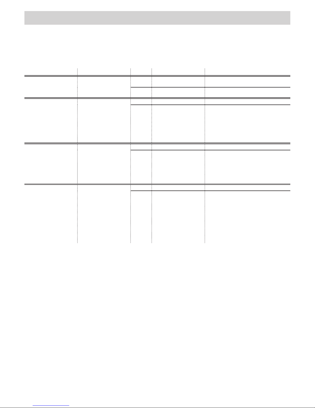
Testing Behavior yes/no Possible cause Remedy
Force cut-off
Try to stop the door wing
while it is closing with
a 50 mm high object.
Does the drive reverse when
it encounters the object?
yes • The force cut-off works
without limitations.
• Leave all settings as they are.
no • Door incorrectly adjusted. • Adjust door, call a technician.
Emergency release
Proceed as described in the
chapter “Operation/use emergency release”.
The emergency release can
be easily actuated (pull once
and the drive releases).
yes • Everything is OK.
no • Drive forces the door
closed.
Door and drive
mechanism is stressed.
• Emergency release
defective.
• Door jams.
• Adjust door CLOSE end switch or switch on
Backjump (DIP switch 6 ON).
• Repair emergency release.
• Check door, see door owner's manual.
Safety contact strip,
if present.
Open and close the door
and actuate the strip at the
same time.
Adjust the behavior of the
door, as set with DIP switch
1, 2 or 3.
yes • Everything is OK.
no • Cable breakage, terminal
loose.
• DIP switch adjusted.
• Strip defective.
• Check the wiring; retighten the terminals.
• Setting the DIP switches.
• Decommission the system and lock it to
prevent reactivation. Then, contact customer
service.
Photo eye, if present
Open and close the door
while interrupting the photo
eye.
Adjust the behavior of the
door, as set with DIP switch
1, 2 or 3.
yes • Everything is OK.
no • Cable breakage, terminal
loose.
• DIP switch adjusted.
• Photo eye dirty.
• Photo eye misadjusted
(holder bent).
• Photo eye defective.
• Check the wiring; retighten the terminals.
• Setting the DIP switches.
• Clean the photo eyes.
• Adjust photo eyes.
• Decommission the system and lock it to
prevent reactivation. Then, contact customer
service.
Page 28
– 28
t
Disassembly
IMPORTANT!
Observe safety information.
The sequence is identical to that described in the “Installation” section,
but in reverse order. Ignore the setting instructions.
Disposal
Observe applicable national regulations.
Warranty and customer service
The warranty complies with statutory requirements. The contact person for
warranties is the specialist retailer.
The warranty is only valid in the country in which the drive was purchased.
Batteries, fuses and bulbs are excluded from the warranty.
If you require after-sales service, spare parts or accessories, please contact
your specialist retailer.
We have tried to make the Installation and Operating Instructions as easy
as possible to follow. If you have any suggestions as to how we could
improve them or if you think more information is needed, please send your
suggestions to us:
Fax.: 0049 / 7021 / 8001-403
email: [email protected]
Miscellaneous
Page 29
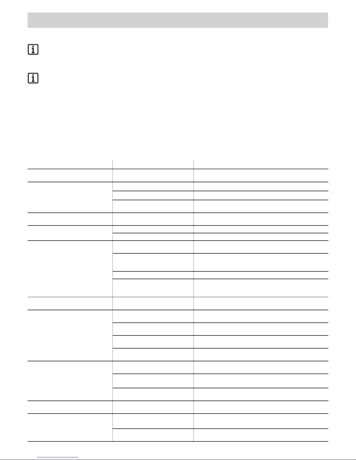
– 29
t
Tips on troubleshooting
HOMELINK-COMPATIBLE!
If your vehicle is equipped with a HomeLink system (Version 7), our drive and radio receiver with 868.6 MHz are compatible.
Another radio frequency (40.685 or 434.42 MHz) must be used with older HomeLink systems. Information can be found under
“http://www.eurohomelink.com” or contact your specialist dealer.
IMPORTANT!
Many malfunctions can be resolved by a controller reset (delete force values), then reprogram the drive.
If you cannot nd the malfunction in the table and eliminate it, take the following actions:
• Perform a controller reset (delete force values) on the controller.
• Disconnect connected accessories (e.g. photo eyes) and reconnect the jumper for a safety connection.
• Set all DIP switches to the factory setting.
• If settings have been changed using TorMinal, perform the controller reset with TorMinal.
• Check all connections on the direct connectors and terminal strip and retighten if necessary.
Drive malfunctions can be corrected according to the following table. If this does not help, contact your specialist dealer for assistance or consult our
website at http://www.sommer.eu.
Malfunction Possible causes Corrective action
Lighting blinks. Drive has not been programmed,
no force values stored.
Program the drive See chapter “Using for the rst time -
programming the drive”.
Drive does not function and lights do not
light up.
No voltage present. Stick in the power mains plug.
No controller installed. Install controller.
Circuit breaker for garage circuit has
tripped.
Replace circuit breaker, check circuit with a different consumer
device (e.g. electric drill).
No lights when opening and closing the
door.
Defective light bulb. Replace light bulb. See chapter “Care and maintenance - light bulb
replacement”.
Drive doesn't function. Controller incorrectly installed. Plug controller correctly into terminal strip.
Photo eyes interrupted. Remove interruption.
Drive does not function when operated
with a hand-held remote control.
Battery in the hand-held remote control
is empty.
Replace battery with new one.
The hand-held remote control has
not been programmed for the radio
receiver.
Programming the hand-held remote control.
Incorrect radio frequency. Check the frequency (868/434 MHz, without external antenna).
The command is constantly pending
because the button of the hand-held
remote control is stuck.
Release the key or replace the hand-held remote control.
Drive does not function when
button-operated.
Button not connected or is defective. Connect button or replace it.
Door stops while closing, moves about
10 cm in the opposite direction, and
stops.
Force cut-off actuated by an obstacle. Remove obstacle, open door completely.
Incorrect force values programmed or
force tolerance set too low.
Wipe force values and teach again.
Guide idler incorrectly adjusted. Readjust the guide idler, see the chapter “Commissioning -
adjusting the door Closed + Open end positions”.
Door incorrectly adjusted or defective
(e.g. spring shaft).
Have door adjusted or repaired by a technician.
Door stops while opening, moves about
10 cm in the opposite direction and
stops.
Force cut-off actuated by an obstacle. Remove obstacle. Move door completely to “door Close” end
position using button.
Incorrect force values programmed or
force tolerance set too low.
Wipe force values and teach again.
Guide idler incorrectly adjusted. Readjust the guide idler, see the chapter “Commissioning -
adjusting the door Closed + Open end positions”.
Door stops while opening. Connected photo eye interrupted and
DIP switch 1 is ON.
Eliminate interruption or turn DIP switch 2 to OFF.
Drive does not close the door. Photo eyes power supply interrupted. • Check connection.
• Replace fuse.
Drive has been disconnected from
mains power supply.
The drive always opens the door completely upon rst command
after the power supply has been restored.
Troubleshooting
Page 30
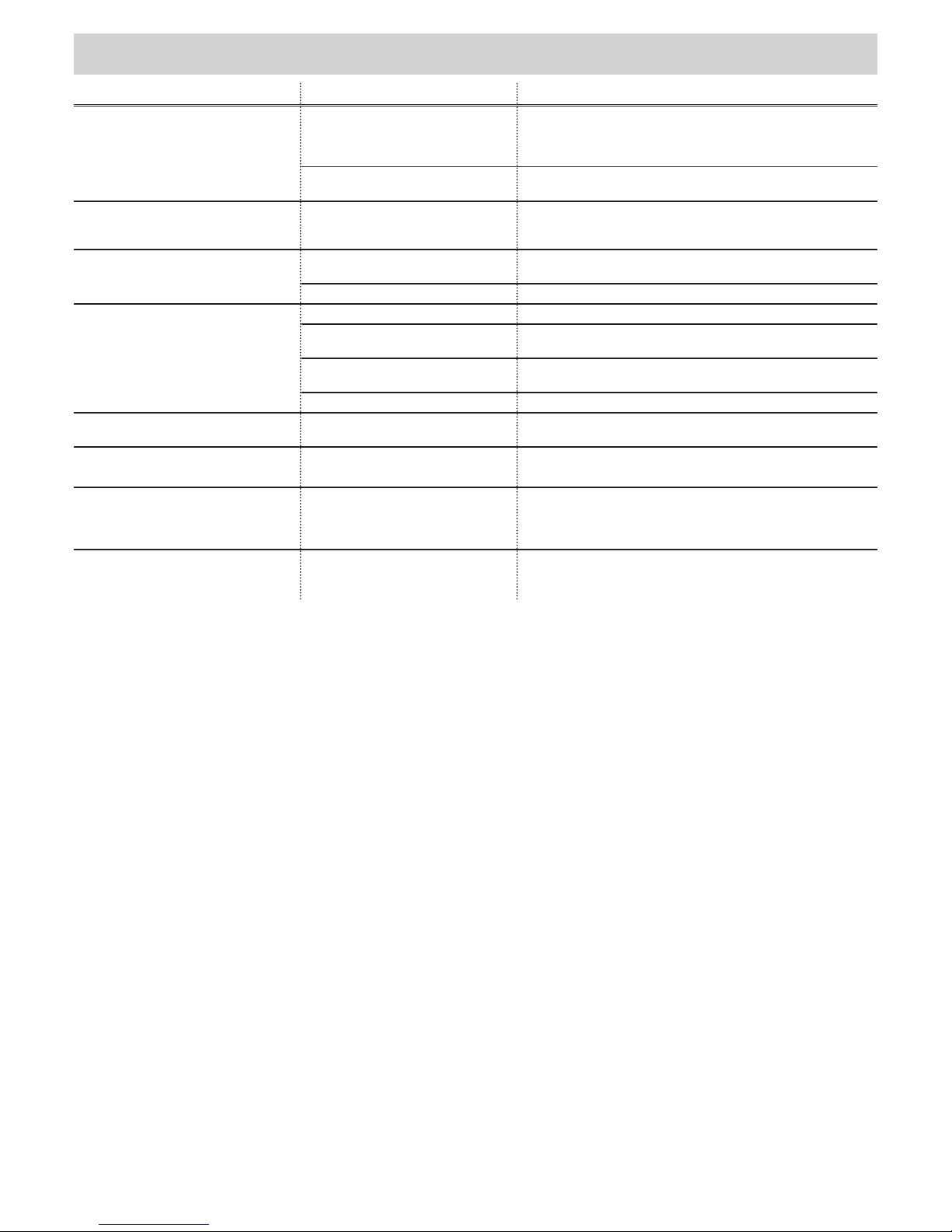
Troubleshooting
t
– 30
Malfunction Possible causes Corrective action
Drive opens the door and then does not
respond to a command from the remote
control or the button.
Safety input tripped (e.g. photo eyes
defective).
• Remove object from photo eye.
• Repair photo eyes.
• Direct connector not properly plugged in.
“Door CLOSE” end switch in the
carriage defective.
Replace end switch.
Drive closes the door and then does not
respond to a command from the handheld remote control or the button.
“Door OPEN” end switch in the
carriage defective.
Replace end switch.
Connected warning light doesn't light up. Defective fuse. Replace fuse; see chapter “Maintenance and care - replace fuse
(warning light connection)”.
Defective light bulb. Replace light bulb of warning light.
Speed varies during opening and closing.
Drive starts slowly and then accelerates.
Soft running, completely normal.
Chain rail dirty. Clean the rail and lubricate again; see chapter “Care and
maintenance - cleaning chains and drive unit rail”.
Chain rail lubricated with incorrect oil. Clean the rail and lubricate again; see chapter “Care and
maintenance - cleaning chains and drive unit rail”.
Chain tightened incorrectly. Tighten the chain; see chapter “Installation - pre-installation”.
Drive does not end learning procedure. End position incorrectly adjusted. Adjusted end position; see chapter “Commissioning - adjusting the
door Closed + Open end positions”.
Radio receiver only!
All LEDs ashing.
All memory locations occupied,
max. 112.
• Delete any hand-held remote controls that are no longer needed.
• Install additional radio receivers.
LED 3.1 or 3.2 lights up continuously. The radio signal is being received; the
button of a hand-held remote control
might be defective or an external signal
is present.
• Remove the battery from the hand-held remote control.
• Wait until the external signal falls off.
LED 3.1 or 3.2 lights up. The radio receiver is in the Learning
mode and awaiting a radio code from a
hand-held remote control.
Press the desired hand-held remote control button.
 Loading...