

SOMFY LT50 CMO, LT60 CMO Installation Instructions Manual
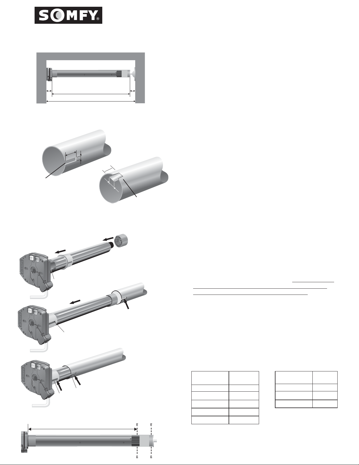
Fig. 1
Fig. 2
C
B =A-(C+D)
Tube Diameter
Less than 3.35"
(85mm)
A
Tube Notch
Length = 25 mm Width=4mmNotch: LT50
LT60 35 mm
LT50/60 CMO Motor
Installation Instructions
B
A
B
Fig. 3
.75"
(20mm)
(25mm)
1"
AB
D
Tube Diameter
Greater than 3.35"
(85mm)
Tube Notch
8mm
1. TUBE PREPARATION
!
Cut the tube to the required length (B), taking into account
the width of the installation (A), the motor end clearance
(C), and the idler end clearance (D). (See Fig. 1)
USE FORMULA TO DETERMINE MEASUREMENTS.
!
Remove all burrs from the ends of the tube and ensure that
!
the inside of the tube is clean.
!
For all round tube sizes up to 3.35" (85 mm) inclusive,
notch the tube on the motor end to the dimensionsA&B.
(See Fig. 2)
!
For all tubes over 3.35" (85 mm) form a tongue in the motor
end of the tube by making two cuts 1" (25 mm) apart and
.75" (20 mm) deep. (See Fig. 3)
2. PREPARING THE TUBULAR MOTOR
Place the crown wheel over the body of the motor. Slide
!
the slot in the motor crown over the raised key on the
motor's limit switch unit. (See Fig. 4)
A crown is not necessary on
2.0" Tube when used with LT50, and
Tube
2.5" with LT60.
Fit the drive wheel on to the output shaft of the motor.
!
There are two types of LT drive wheels: Removable or
"SOFT CLIP" "HARD CLIP"
"SOFT CLIP"
type, and fixed or type. The
drives are available for round tubes in
only
2.0", 2.5", and 2.75" diameters. The drive wheel can be
removed by physically pulling it off the motor shaft. For the
ease of identification all drives are
The drives can only be removed from the
"HARD CLIP"
"SOFT CLIP" BROWN.
shaft by pressing the two clips inward at the same time.
The motor must be out of the tube in order to have access
to the clips. These drives are
BLACK.
Raised Key
Raised Key
Raised Key
Notch
Fig. 4
Fig. 5
Fig. 6
R
3. FITTING THE MOTOR INTO THE TUBE
For round tubes: Measure the drilling length R according to
the motor type listed in the table below.
Fit the motor into
the tube ensuring that the notch at the end of the tube
slides over the raised key on the crown wheel.
(See Fig. 5,
6) Secure the drive wheel to the tube using four 7/32 steel
pop rivets or four 1/4 DIA. screws.
Fit the end plug into the
other side of the tube and secure it with three steel pop
rivets. Use only fasteners with steel grades SAE 5 or higher.
Metric fasteners must be grade 8.8 or higher. (See Fig. 7)
LT50 CMO
MOTOR
TYPE
525A2 CMO
530R2 CMO
535A2 CMO
540R2 CMO
550R2 CMO
R
in./mm
22.80/579
22.80/579
25.55/649
25.55/649
25.55/649
LT60 CMO
MOTOR
TYPE
660R2 CMO
680R2 CMO
6100R2 CMO
in./mm
24.8/630
26.2/665
26.2/665
R
Fig. 7

4. LIMIT SWITCH SETTING
AWNING HOOD
SOMFY strongly recommends using a Tester Cable (T.C.)
Cat. No. 6020086 to set the motor limits, and to ensure
the system is operating correctly before the final electrical
connection is made. Refer to Step 6 "Trouble Shooting
Guide" for any problems encountered.
Two positions have to be set: the UP & DOWN
positions, this is where the rolling shutter or awning
will stop automatically.
Sequence:
Ensure the tester cable switch is in the center "OFF"
1
position, and connect T.C. to motor leads by matching
color codes.
2
Remove the protective cap covering the limit setting
buttons on motor head, and replace when finished.
3
Depress fully both limit switch push buttons. They will
automatically lock in the down position. Operate the T.C.
switch and check that the system operates correctly.
Identify the UP limit switch push button(refer to figure
used for step 1). Press the T.C. switch in the UP direction
until the required position is reached. Set the switch to
the center "OFF" position.
4
Unlock the UP limit switch push button by depressing
and releasing it.
5
Repeat the above operation to set the lower limit.
Check with the switch that the motor stops at the up &
down positions just set.
6
Always remember to affix the protective cap over the
limit switch buttons.
NOTE:
Tubular motors are not continuously rated. They
have a built-in thermal overload device which limits their
operation to approximately 5 minutes.
UP POSITION
DOWN POSITION
Cat. No. 6020086
Tester Cable Switch
(T.C. switch)
1
2
** The motor cable should not act as a direct
conduit for the water to enter the head of
the motor (form drip loops).
WHITE PUSH
BUTTON
(BLACK WIRE)
YELLOW PUSH
BUTTON
(RED WIRE)
63 4 5
AWNING HOOD
5. WIRING/INSTALLATION RECOMMENDATIONS
A. All wiring must conform to NEC (National Electrical Code)
and local codes
B. Do not wire two or more motors to one SPDT (single pole
double throw switch-NO PARALLEL WIRING).
C. Do not use light switches.
D. Do not wire two or more switches to one motor, without
using SOMFY's multi switch command. Cat. No. 6300427.
NOTE: SOMFY motors conform to IP44 requirements and
as such must be protected against direct weather elements
such as rain, sleet,...etc.
SOMFY reserves the right to void the motor warranty
if the wiring recommendations are not followed.
6. TROUBLESHOOTING GUIDE
SYSTEM DOES NOT RESPOND
- Is the power supply switched on - check any fuses in the
system?
- Is control switch wired correctly? Refer to instructions.
- Are limit switches set properly? Review limit switch settings.
- The thermal protective device may have shut the motor off.
Wait for the motor to cool down.
- Check the wiring between the motor & the switch.
- Disconnect the switch & test the motor with a tester cable.
Power
GREEN
120VAC 60Hz
GROUND
** See note above
NEUTRAL
LINE
BLACK
* - reverse the brown
BLACK
RED
BROWN
BROWN*
RED*
DECORATOR PADDLE/
TOGGLE SWITCH
and red wire if the UP
and DOWN movement
do not correspond to the
UP and DOWN of the switch.
BLACK
GROUND
CONNECTED TO BOX
THE SYSTEM IS NOT STOPPING
- Is the limit switch crown wheel being driven by the tube (has tube
profile been properly notched)?
- Is motor drive wheel securely fastened to the tube?
NOTE: if the motor is tested outside the tube, the crown wheel
has to be manually turned in order to stop the rotation of the
output shaft.
SOMFY SYSTEMS, INC. reserves the
right to update, change or modify
these instructions without prior notice.
REF. NO. 4500049 / 900245
c AUGUST 1999
SOMFY MEXICO S.A. De C.V.
SOMFY MEXICO S.A. De C.V.
Calle 3 No. 47, Loc. E-5
Fracc Ind. Alce Blanco
Nau., Edo. de Mex C.P. 53370
SOMFY SYSTEMS, INC.
47 Commerce Drive
Cranbury, NJ 08512
SOMFY CANADA
6315 Shawson Drive, Unit #1
Mississauga, Ontario L5T1J2
 Loading...