

SOMFY LS40 404R2, LS40 409R2, LS40 401F1, LS40 404S2, LS40 412R2 Installation Instructions Manual
Page 1
LS40 Motor
Installation Instructions
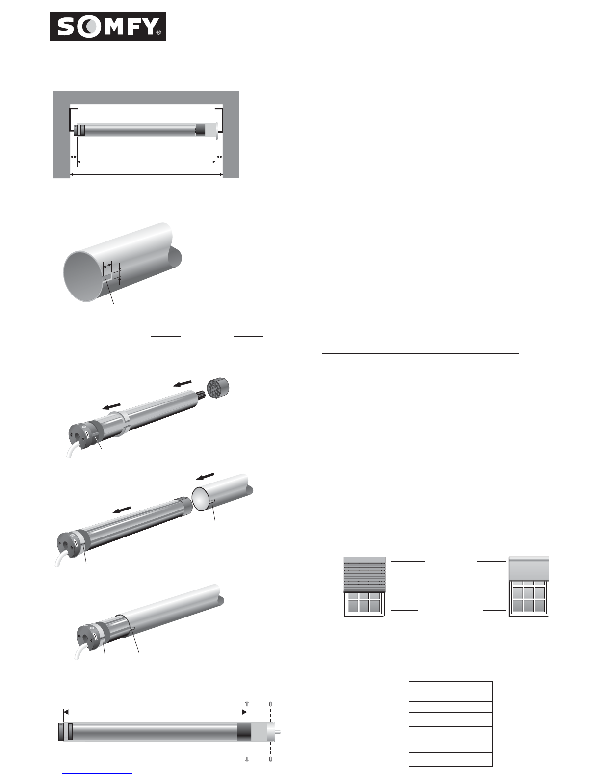
Fig. 1
C
Motor End Idler End
B
A
B =A-(C+D)
1. TUBE PREPARATION
!
Cut the tube to the required length (B), taking into account
the width of the installation (A), the motor end clearance,
which includes motor head and motor bracket thickness
(C), and the idler end clearance, which includes idler end
D
cap and idler bracket thickness (D). (See Fig. 1)
!
USE FORMULA TO DETERMINE MEASUREMENTS.
!
Remove all burrs from the ends of the tube and ensure that
the inside of the tube is clean.
!
For all round tubes, notch the tube on the motor end to the
dimensionsA&B.(See Fig. 2)
For All Round Tubes
A
Fig. 2
B
Tube Notch
AB
Notch: LS40 in./mm in./mm
Length = Width =
.335 / 8.5 .236 / 6
Fig. 3
Raised Key
Fig. 4
Notch
2. PREPARING THE TUBULAR MOTOR
!
Carefully pull open the one piece crown in order to fit over
the body of the motor. Slide the opening of the crown
wheel over the recessed part of the motor's limit switch unit
and close it over the Raised Key. (See Fig. 3)
!
Fit the drive wheel onto the output shaft of the motor.
3. FITTING THE MOTOR INTO THE TUBE
For round tubes: Measure the drilling length R according to
the motor type listed in the table below.
Fit the motor into
the tube ensuring that the notch at the end of the tube
slides over the raised key on the crown wheel.
(See Fig.4 &
5) Secure the drive wheel to the tube using four 5/32 steel
pop rivets or four #10 screws.
Fit the end plug into the
other side of the tube and secure it with three steel pop
rivets. Use only fasteners with steel grades SAE 5 or higher.
Metric fasteners must be grade 8.8 or higher. (See Fig. 6)
4. LIMIT SWITCH SETTING
SOMFY strongly recommends using a Tester Cable (T.C.) Cat.
No. 6020086 to set the motor limits, and to ensure the system
is operating correctly before the final electrical connection is
made. Refer to Step 6 "Trouble Shooting Guide" for any
problems encountered.
Two positions have to be set: the UP & DOWN positions,
this is where end product will stop automatically.
Raised Key
Fig. 5
Raised Key
Fig. 6
Notch
R
UP POSITION
DOWN POSITION
LS40
MOTOR
TYPE
401F1
404R2
404S2
409R2
412R2
R
in./mm
16.6/421
16.6/421
16.6/421
16.6/421
16.6/421
Page 2
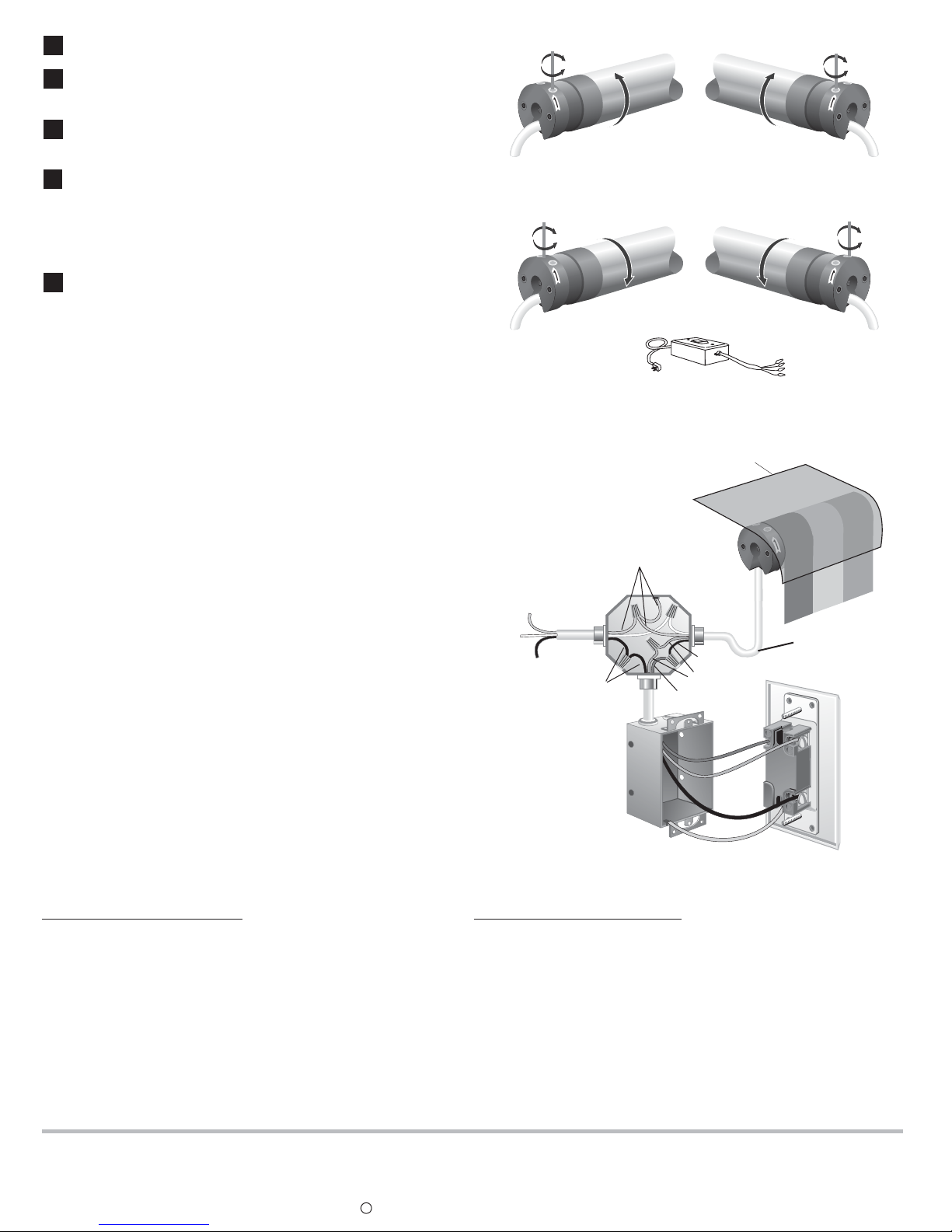
Adjustment of Upper and Lower Positions for the LS40
1
Ensure the tester cable switch is in the center "OFF" position,
and connect T.C. to motor leads by matching color codes.
2
Identify the UP recessed limit screw by finding the arrow on
the motor head which points in the direction that retracts (rolls
up) the system.
Turn the power on to ensure that the switch is operating
3
properly (UP-raises, DOWN-lowers). If not, turn the power off
and simply reverse the black and red motor leads.
4
Flip the tester cable switch in the UP direction. If the system
stops before its UP limit, turn the UP screw to " " until
+
necessary. If the system does not stop at its UP limit, flip the
tester cable switch in the DOWN direction and turn the UP
screw to " ". Repeat this until the correct setting is achieved.
-
NOTE: 7 turns of Hex Screws equals 1 turn of roller tube.
5
Flip the tester cable switch in the DOWN direction. If the
system stops before its DOWN limit, turn the DOWN limit
screw to " ". If not, flip the tester cable switch in the UP
direction and turn the DOWN limit screw to " ". Repeat this until
+
-
the correct setting is achieved.
NOTE: Recessed thumbscrews can accommodate a flat
head screwdriver (4mm wide max.), SOMFY's Allen wrench
(Cat. No. 6500258) or Flexible limit switch adjuster (Cat.
No. 6500091).
Stop Position 1
(Black Wire Direction)
Stop Position 2
(Red Wire Direction)
-
+
Motor on Left
-
+
Motor on Left
-
+
Motor on Right
(Red Wire Direction)
-
+
Motor on Right
(Black Wire Direction)
Tester Cable Switch
Cat. No. 6020086
NOTE: Tubular motors are not continuously rated. They
have a built-in thermal overload device which limits their
operation to approximately 5 minutes. A maximum 15
minute cool down period is required if the motor reaches
thermal overload.
5. WIRING/INSTALLATION RECOMMENDATIONS
A. All wiring must conform to NEC (National Electrical Code)
and local codes
B. Do not wire two or more motors to one SPDT (single pole
double throw switch-NO PARALLEL WIRING).
C. Do not use light switches to control SOMFY motors.
D. Do not wire two or more switches to one motor, without
using SOMFY's multi switch command. Cat. No. 6300427.
NOTE: SOMFY motors conform to IP44 requirements and
as such must be protected against direct weather elements
such as rain, sleet,...etc.
6. TROUBLESHOOTING GUIDE
SYSTEM DOES NOT RESPOND
- Is the power supply switched on - check any fuses in the
system?
- Is control switch wired correctly? Refer to instructions.
- Are limit switches set properly? Review limit switch
settings.
- The thermal protective device may have shut the motor off.
Wait for the motor to cool down.
- Check the wiring between the motor & the switch.
- Disconnect the switch & test the motor with a tester cable.
HOOD
** The motor cable should not act
as a direct conduit for the water to
enter the head of the motor (form
drip loops).
Power
120VAC 60Hz
GROUND
NEUTRAL
LINE
BLACK
* - reverse the brown
and red wire if the UP
and DOWN movement
do not correspond to the
UP and DOWN of the switch.
THE SYSTEM IS NOT STOPPING
- Are limit switches set properly? Review limit switch settings.
- Is the limit switch crown wheel being driven by the tube (has tube
profile been properly notched)?
- Is motor drive wheel securely fastened to the tube?
NOTE: if the motor is tested outside the tube, the crown wheel
has to be manually turned in order to stop the rotation of the
output shaft.
GREEN
BLACK
RED
BROWN
BROWN*
RED*
BLACK
GROUND
CONNECTED TO BOX
** See note above
DECORATOR PADDLE/
TOGGLE SWITCH
SOMFY reserves the right to void the motor warranty if the wiring recommendations are not followed.
SOMFY SYSTEMS, INC. reserves the
right to update, change or modify
these instructions without prior notice.
REF. NO. 4500047/900246A
SOMFY MEXICO S.A. De C.V.
Calle 3 No. 47, Loc. E-5
Fracc Ind. Alce Blanco
Nau., Edo. de Mex C.P. 53370
SOMFY SYSTEMS, INC.
47 Commerce Drive
Cranbury, NJ 08512
c SOMFY SYSYTEMS, INC., FEBRUARY 2000
SOMFY CANADA
6315 Shawson Drive, Unit #1
Mississauga, Ontario L5T1J2
 Loading...