

Page 1
Installation Instructions
LS40, LT50/60, LT50 RH
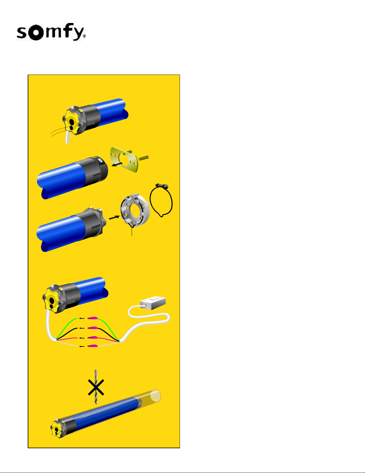
Motor Cable Positioning
Depending on the application, the motor cable can pass
through the center or side of the motor head. In the
LT50/60 versions simply raise the yellow cover plate
slightly, reposition the cable and then press the cover plate
into place.
Mounting the Motorized Tube
LS40 and LT50 RH
The motor brackets for the LS40 and LT50 RH are screwed
directly into the head of the motor as illustrated at left.
Locking
H
LTR
50
LT
Spring Ring or
Locking Spring Ring
Cat.# 4350027
Spring Ring
LT50/60
The motor brackets for the LT50/60 are equipped with a
spring ring. This spring ring must be used and does not
have to be removed for installation. You can press the
motor axially into the motor bracket in any of 6 positions,
so that the limit switch adjustment buttons are always
easily accessible. When the motor engages the motor
bracket, the spring ring makes a click sound. The spring
ring keeps the motor head securely seated in the bracket
for even torque distribution. For higher torque applications
a locking spring ring with screw must be used in place of
the standard spring ring.
Testing the Motor - Test Run 1
- Connect the motor tester cable (Cat. No. 6020086) to the
motor cable, match the wire colors and connect to power.
Motor Tester
Cable
- Remove yellow protective cap from limit switch
adjustment buttons.
- Press both limit switch adjustment buttons in (they will
automatically remain locked).
When the limit switch adjustment buttons are pushed in,
the motor has no stop position shut-off points. The
number of revolutions is unlimited.
Attaching Rolling Shutter , Awning, Screen...
Now you can attach the interior, or exterior window
treatment to the tube.
Caution! Never drill in the vicinity of the motor , or use
screws that could penetrate the motor.
63
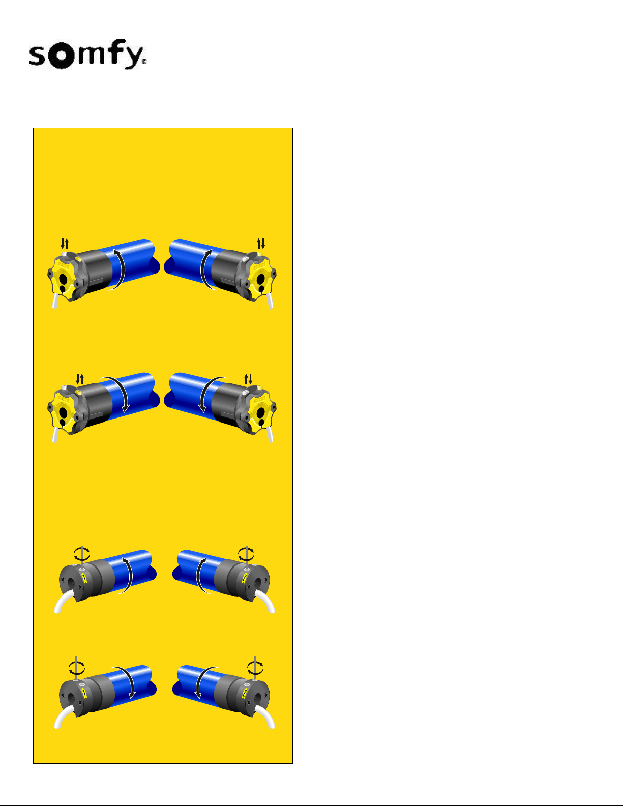
Adjustment of Upper and Lower P ositions for
LT50/60 motors
- Both limit switch adjustment buttons have been
depressed since Test Run 1.
Stop Position 1
- Bring end product into the desired stop position 1
(direction of rotation 1)
- Release the limit switch adjustment button that lies in the
direction of rotation 1 by pressing it down again.
Stop position 1 is now set.
Page 2
Installation Instructions
LS40, LT50/60, LT50 RH
LT50/60 and LT50RH
Stop Position 1
Depending upon type of installation
Motor on Left
Position 2
Motor on Right
Stop position 2
- Bring end product into stop position 2
(direction of rotation 2)
- Release the limit switch adjustment button that lies in the
direction of rotation 2 by pressing it down again.
Stop position is now set.
Always attach protective cap over limit switch adjustment
buttons.
NOTE: It is important to note that SOMFY motors are
weatherproof, but NOT WATERPROOF and therefore the
motor head should not be exposed to direct rainfall.
Test Run 2
Allow the motor to run in both directions, until it shuts off in the
stop positions. Because of the built-in thermal protection
feature, the motor may shut off automatically after running
without interruption for an extended period of time. Please wait
until the motor has cooled off and is ready for operation again
(approximately 10-15 minutes).
Motor on Left
LS40
Stop Position 1
Depending upon type of installation
Motor on Left
Stop Position 2
Motor on Right
Motor on Right
Changing a Set Stop Position...
- Press the limit switch adjustment button that lies in the
direction of rotation.
- Bring the end product into the desired stop positon.
- Release the limit switch adjustment button by pressing it
down again.
Adjustment of Upper and Lower P ositions for the
LS40 Motor
- Connect the motor tester cable (Cat. No. 6020086) to the
motor cable, match the wire colors and connect to power.
- Identify the UP recessed limit screw by finding the arrow on
the motor head which points in the direction that retracts
(rolls up) the system.
- Turn the power on to ensure that the switch is operating
properly (UP-raises, DOWN-lowers). If not, turn the power off
and simply reverse the black and red motor leads.
- Flip the tester cable switch in the UP direction. If the system
stops before its UP limit, turn the UP screw to "+" until
necessary. If the system does not stop at its UP limit, flip the
tester cable switch off and turn the UP screw to "-". Repeat
this until correct setting is achieved.
NOTE: 7 T urns of Hex Screws equals 1 turn of roller tube.
- Flip the tester cable switch in DOWN direction. If the system
stops before its DOWN limit, turn the DOWN limit screw to
"+". If not, flip the tester cable switch off and turn the DOWN
limit screw to "-". Repeat this until correct setting is achieved.
Motor on Left
Motor on Right
NOTE: Recessed thumbscrews can accomodate a flat
head screwdriver, SOMFY’s Allen wrench or Flexible limit
switch adjuster.
64
 Loading...