

Page 1
Operating
and installation guide
www.somfy.fr
Lighting Indoor RTS
Ref.5054480A
Page 2

1. Brief overview of the Lighting Indoor RTS 3
2. Safety - Important information 3
2.1 Installation and commissioning
3
2.2 Operating 4
2.3 Environment 4
3. Content of the kit and tools required 4
3.1 List of parts
4
3.2 Tools required 4
4. The Lighting Indoor RTS in detail 5
4.1 Components
5
4.2 Technical data 5
5. Mounting the Lighting Indoor RTS 6
5.1 Before mounting the Lighting Indoor RTS
6
5.2 Recessed mounting 6
5.3 Mounting and assembly on a surface 8
6. Programming the control point 9
6.1 Accessing the Lighting Indoor RTS PROG button
10
6.2 Identifying the control point 10
6.3 One-touch point 10
6.4 Point with Up/STOP/Down buttons 14
6.5 Timer 16
6.6 Situo control point 18
6.7 Telis 1 RTS/Telis Soliris RTS remote controls 19
6.8 Telis 4 RTS/Telis 4 Soliris RTS remote controls 21
7. Replacing a lost or broken control point 22
8. Everyday use of the Lighting Indoor RTS 22
8.1 Operating
22
8.2 Maintenance 23
9. Problems with the Lighting Indoor RTS? 24
10. Changing the fuse 25
Contents
Lighting Indoor RTS
2
Copyright © 2008 Somfy SAS. All rights reserved.
Page 3

Somfy’s expertise delivers satisfaction guaranteed.
Thank you for choosing a Somfy Lighting Indoor RTS.
Before installing and using the Lighting Indoor RTS, please read this
guide carefully.
Somfy solutions animate your lights and entrances to bring your whole
house alive. Somfy solutions are designed so that everyone can enjoy
the benets of the products in their home, based on their specic
requirements.
In this guide, the term ‘product’ can include your awning, blind, curtain,
garage door, gate, projection screen, roller shutter.
Well thought-out and easy to use, Somfy solutions are one of life’s little
daily pleasures, making home life more enjoyable.
1. Brief overview of the Lighting Indoor RTS
The Lighting Indoor RTS is used to control one or more incandescent or
halogen bulbs from a single control point equipped with Radio Technology
Somfy (RTS).
The Lighting Indoor RTS is tted in place of the original switch. The
RTS control point to which it is connected becomes the new switch for
controlling lighting in the room. The Lighting Indoor RTS cannot be used
to control neon lighting, a 24 V bulb supplied by a transformer, or a bulb
with a dimmer switch.
The maximum power of all the bulbs connected to a Lighting Indoor RTS
is 500 W.
The Lighting Indoor RTS is used as:
an individual control, with one Lighting Indoor RTS controlling one •
or more bulbs up to 500W combined power;
a group control - several Lighting Indoor RTS are controlled from a •
single control point (advanced installation function), or;
a multiple control - one Lighting Indoor RTS is controlled by •
several control points (up to a maximum of 12) (advanced installation
function).
2. Safety - Important information
2.1 Installation and commissioning
Read this guide carefully before installing and using the Lighting Indoor RTS.
This guide describes the installation, commissioning and use of the
Lighting Indoor RTS.
Lighting Indoor RTS
3
Copyright © 2008 Somfy SAS. All rights reserved.
3
Page 4
Lighting Indoor RTS
4
Copyright © 2008 Somfy SAS. All rights reserved.
Before beginning installation, make sure that the Lighting Indoor RTS is
compatible with the equipment and associated accessories.
Any incorrect use will invalidate the warranty and Somfy's liability.
2.2 Operating
Always make sure the power supply is off before beginning any
installation, mounting, disassembly or maintenance operations on the
Lighting Indoor RTS and associated bulbs.
Do not allow children to play with the xed control points. Keep remote
-
controls out of the reach of children.
Never immerse or soak the Lighting Indoor RTS in any liquid.
-
Only use maintenance products recommended by Somfy. -
2.3 Environment
Damaged electrical or electronic products, such as used batteries, should
not be disposed of with household waste. Please take them to a collection
point or an approved centre to ensure they are recycled correctly.
3. Content of the kit and tools required
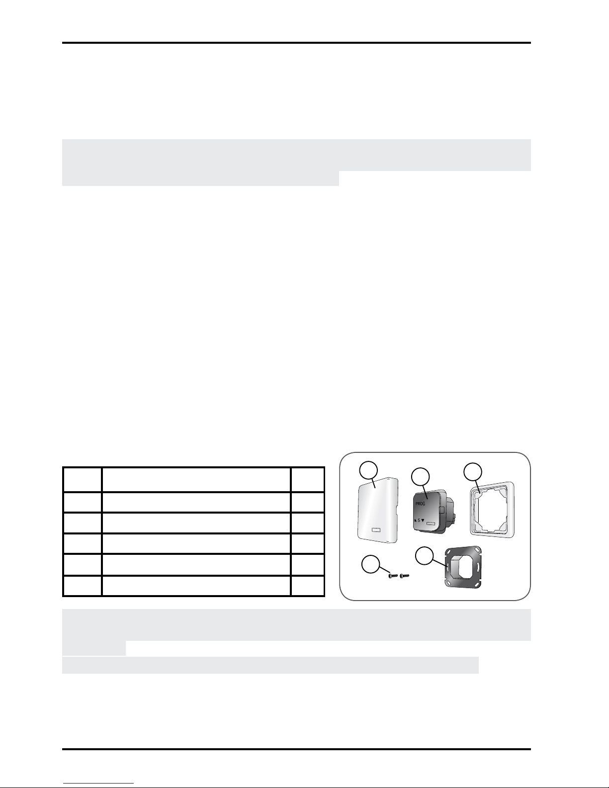
3.1 List of parts
Before beginning installation and commissioning of the Lighting Indoor -
RTS, check that all parts listed in the following table are present in the
correct quantity (Q):
No. Components Q.
1 Cover 1
2 Lighting Indoor RTS 1
3 Frame 1
4 Screw 2
5 Bracket 1
To install the Lighting Indoor RTS on a surface, use only the Somfy
housing for surface mounting designed for the Lighting Indoor RTS (not
supplied).
Caution: The frame (3) can only be used for recessed mounting.
1
2
3
4
5
Page 5
Lighting Indoor RTS
5
Copyright © 2008 Somfy SAS. All rights reserved.
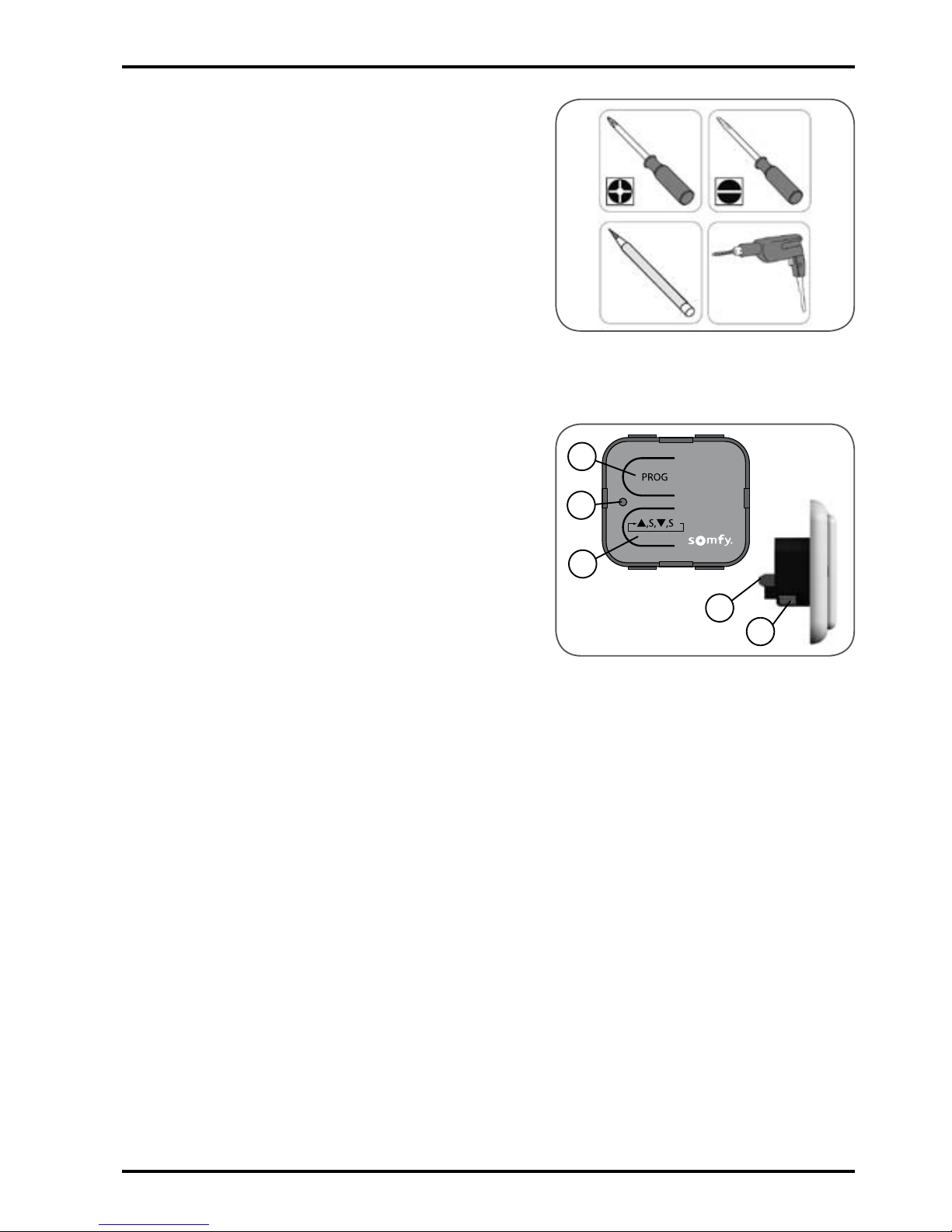
3.2 Tools required
Appropriate screwdriver for the •
screws to be used
Insulated athead electricians •
screwdriver
Drill and drill bit•
Pencil•
4. The Lighting Indoor RTS
in detail
4.1 Components
A. Programming button (PROG)
B. Indicator light
C. Manual On/Off control button
D. Fuse
E. Electrical connection terminal.
4.2 Technical data
Dimensions in mm (H x w x d): 80 x 80 x 45 mm
Operating temperature: + 5°C to + 40°C
Protection rating: Inside use, in a dry room - IP 30
Frequency: 433.42 MHz
Range: 20 m through two concrete walls; 200 m in open space
Power supply: 230 V; 50 Hz
Fuse: 3.15 A
Power: 500 W max.
A
C
B
D
E
Page 6

Lighting Indoor RTS
6
Copyright © 2008 Somfy SAS. All rights reserved.
5.2 Recessed mounting
Somfy recommends tting the Lighting
Indoor RTS in place of the original
switch.
Check that the bulbs work.
-
Cut off the mains power supply. -
Remove the original switch to access -
the housing for recessed mounting.
Screw the mounting bracket (5) onto
-
the housing using the screws supplied.
Note: If the screws provided are lost, do
not use roundhead screws. Only use
5. Mounting the Lighting Indoor RTS
5.1 Before mounting the Lighting Indoor RTS
5.1.1 Distances
150cm = Minimum distance to be kept between a Lighting Indoor RTS -
and the ground.
30cm = Minimum distance to be kept between a Lighting Indoor RTS
-
and another RTS component: (e.g. between any RTS control
points and/or between any control point and any motor).
20cm = Minimum distance to be kept between two Lighting Indoor RTS:
-
(e.g. between any RTS control points and/or between any
control point and any motor).
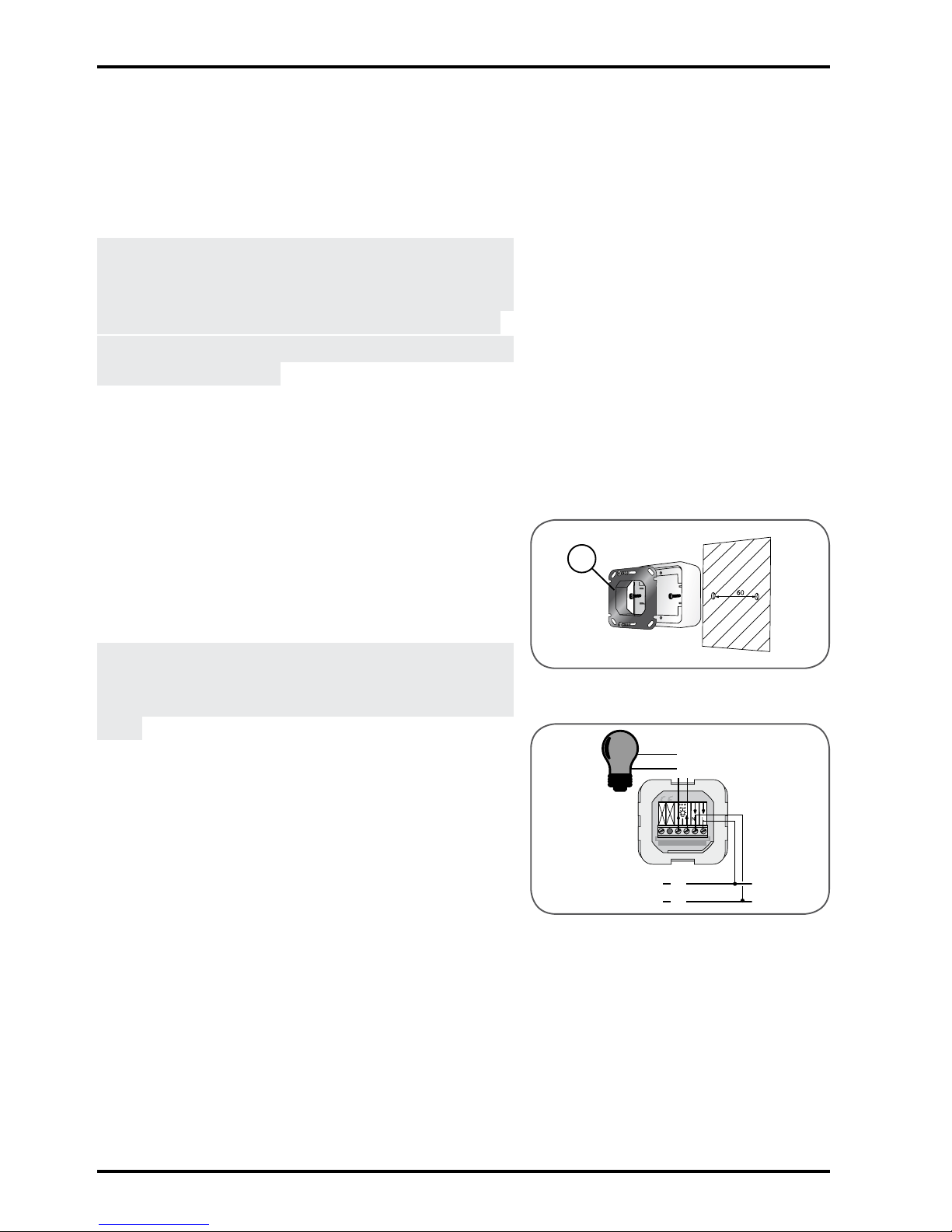
5.1.2 Conditions
Note: Do not mount the Lighting Indoor RTS on a metal surface.
The Lighting Indoor RTS must only be installed indoors.
-
Mount the Lighting Indoor RTS in a housing for recessed mounting -
which is 60 mm in diameter (minimum depth: 40 mm) or in a Somfy
housing for surface mounting (not supplied).
Caution! To install the Lighting Indoor RTS on the surface of a wall, only
use the Somfy housing for surface mounting which is compatible with the
Lighting Indoor RTS (not supplied).
Always leave the front panel of the Lighting Indoor RTS clearly
-
accessible; never place anything in front.
Check the radio range after mounting the Lighting Indoor RTS. The
-
radio range is limited by the radio appliance control standards.
5
Page 7
Lighting Indoor RTS
7
Copyright © 2008 Somfy SAS. All rights reserved.
athead screws with a diameter of 3
mm.
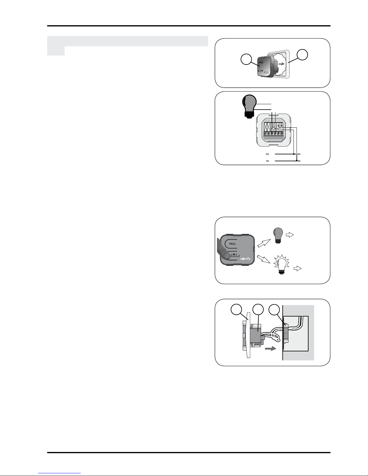
Place the Lighting Indoor RTS (2) inside
-
the frame (3).
Wire the Lighting Indoor RTS according
-
to the diagram opposite:
(a) / (b) = Output•
(L) = Live•
(N) = Neutral•
Ensure that no pressure is exerted on
-
the wires from the Lighting Indoor RTS
terminal.
Check the Lighting Indoor RTS wiring:
-
Press the Lighting Indoor RTS -
manual control button.
If the bulb connected to the
►
Lighting Indoor RTS does not light
up, see section 9 "Problems with
the Lighting Indoor RTS?".
If the bulb connected to the Lighting
►
Indoor RTS lights up, the Lighting
Indoor RTS is correctly wired.
Insert the Lighting Indoor RTS assembly
-
(2) and the frame (3) into the bracket
(5):
Position the assembly so that
-
"PROG" can be read.
Press the Lighting Indoor RTS until
-
a click is heard: the Lighting Indoor
RTS is correctly tted into the
bracket .
Ensure that the wires are not
-
squashed by the Lighting Indoor
RTS terminal when pushing into the
recess tting.
Follow the steps described in section 6
-
"Programming the control point" before
tting the cover.
a
b
L
N
2
3
3
5
2
OK
Section 9
Page 8
Lighting Indoor RTS
8
Copyright © 2008 Somfy SAS. All rights reserved.
5.3 Mounting and assembly on
a surface
Somfy recommends tting the Lighting
Indoor RTS in place of the original
switch.
To install the Lighting Indoor RTS on a
surface, only use the Somfy housing for
surface mounting which is compatible
with Lighting Indoor RTS (not supplied).
Caution: The frame (3) is not used for
surface mounting.
Check that the bulbs work.
-
Cut off the mains power supply. -
Remove the original switch to access -
the housing for recessed mounting.
Mount the Somfy housing for surface
-
mounting to the wall.
Screw the bracket (5) onto the surface
-
mounting housing using the screws
supplied.
Note: If the screws provided are lost, do
not use roundhead screws. Only use
athead screws with a diameter of 3
mm.
Wire the Lighting Indoor RTS according
-
to the diagram opposite:
(a) / (b) = Output•
(L) = Live•
(N) = Neutral•
Ensure that no pressure is exerted on
-
the wires from the Lighting Indoor RTS
terminal.
a
b
L
N
5
Page 9
Lighting Indoor RTS
9
Copyright © 2008 Somfy SAS. All rights reserved.
Check the Lighting Indoor RTS wiring: -
Press the Lighting Indoor RTS -
manual control button.
If the bulb connected to the
►
Lighting Indoor RTS does not light
up, see section 9 "Problems with
the Lighting Indoor RTS?".
If the bulb connected to the Lighting
►
Indoor RTS lights up, the Lighting
Indoor RTS is correctly wired.
Insert the Lighting Indoor RTS (2) into
-
the bracket (5).
Position the Lighting Indoor RTS so
-
that "PROG" can be read.
Press the Lighting Indoor RTS until
-
a click is heard: the Lighting Indoor
RTS is correctly tted into the bracket
so that the wires are not pinched.
Ensure that the wires are not
-
squashed by the Lighting Indoor
RTS terminal when pushing into the
aasembly tting.
Follow the steps described in section 6
-
"Programming the control point" before
tting the cover.
OK
Section 9
2
5
6. Programming the control point
To commission the Lighting Indoor RTS, a RTS control point must be
recorded in the Lighting Indoor RTS.
This control point is used to switch bulbs connected to the Lighting Indoor
RTS on or off.
N.B.: These instructions only describe the installation procedure for an
"individual control" type Lighting Indoor RTS. Refer to the instructions for
advanced functions available on the Internet (address on the back cover
of these instructions) to install a "group control" or a "multiple control".
Page 10

Lighting Indoor RTS
10
Copyright © 2008 Somfy SAS. All rights reserved.
6.1 Accessing the Lighting
Indoor RTS PROG button
The PROG button (A) is located near the
word "PROG", above the indicator light
(B) and is shaped like a tab.
6.2 Identifying the control
point
Identify the control point in the list below -
and refer to the section indicated to
program the control point in the Lighting
Indoor RTS:
1) Control point tted to the wall with
a single button, called a One-touch
point, see paragraph 6.3;
2) Control point tted to the wall with
Up/STOP/Down buttons, called a Point
with Up/STOP/Down buttons, see
paragraph 6.4;
3) Programmable control point, called
a Timer, see paragraph 6.5;
4) Situo control point tted to the wall,
see paragraph 6.6;
5a) Telis 1 RTS remote control, see
paragraph 6.7;
5b) Telis Soliris RTS remote control,
see paragraph 6.7;
6a) Telis 4 RTS remote control, see
paragraph 6.8;
6b) Telis 4 Soliris RTS remote control,
see paragraph 6.8.
6.3 One-touch point
6.3.1 Identifying the model
Check that the control point has an -
elongated button.
Remove the front cover from the
-
one-touch point:
5b
5a
6a 6b
3
2
1
4
A
B
Page 11

Lighting Indoor RTS
11
Copyright © 2008 Somfy SAS. All rights reserved.
One-touch point with a white and grey front
cover:
Gently remove the front cover with a -
at, pointed tool (such as a athead
screwdriver) where the white section
and the grey section join.
Lever it and lift the cover upwards,
-
without using force, to detach the
mounting lugs from the front cover.
One-touch point with a white front cover:
Lever it with a at, pointed tool (such as a athead screwdriver), without
using force, around the upper
section of the front cover to detach
it from its bracket.
Turn the front cover over to nd out the
-
model:
If there is a metal plate inscribed
-
PROG next to the battery: model A.
If there is no metal plate inscribed
-
PROG next to the battery: model B.
6.3.2 Programming a control point in
the Lighting Indoor RTS
Model A:
Restore the electric power supply. -
Press and hold the PROG button (A) on -
the Lighting Indoor RTS:
The indicator light comes on.
►
The bulb connected to the Lighting ►
Indoor RTS comes on and then
goes off.
The Lighting Indoor RTS
►
PROG function is activated for
approximately 2 minutes.
A B
{
A
Page 12

Lighting Indoor RTS
12
Copyright © 2008 Somfy SAS. All rights reserved.
Take the one-touch control point. -
Make a contact between the PROG -
metal plate (a) on the electrical circuit
and the battery bracket using a athead
screwdriver:
The Lighting Indoor RTS indicator
►
light ashes.
The bulb connected to the Lighting
►
Indoor RTS comes on and then
goes off.
The control point is programmed
►
in the Lighting Indoor RTS.
Press the switch on the control point:
-
If the bulb connected to the Lighting -
Indoor RTS lights up, the Lighting
Indoor RTS works.
If the bulb connected to the Lighting
-
Indoor RTS does not light up, contact
the Somfy assistance service.
Fit the cover (1) on the Lighting Indoor
-
RTS:
Place the cover on the Lighting
-
Indoor RTS so that the Somfy logo
can be seen in the bottom righthand side.
Press on the cover until a click is
-
heard: the cover is correctly tted
onto the Lighting Indoor RTS.
Ret the control point front cover:
-
One-touch point with a white and grey front
cover:
Insert the mounting lugs into their -
notches on one side of the front
cover.
Press on the other side until it clicks,
-
to x the front cover in its bracket
One-touch point with a white front cover:
Ret the front cover on its bracket -
{
PROG
1
1
a
Page 13

Lighting Indoor RTS
13
Copyright © 2008 Somfy SAS. All rights reserved.
Model B:
Restore the electric power supply. -
Press and hold the PROG button (A) on -
the Lighting Indoor RTS:
The indicator light comes on.
►
The bulb connected to the Lighting ►
Indoor RTS comes on and then
goes off.
The Lighting Indoor RTS
►
PROG function is activated for
approximately 2 minutes.
Take the one-touch control point.
-
Remove the battery from the one-touch -
control point using a plastic object.
Press on the centre section of the
-
one-touch point button.
Ret the battery in the base of its
-
bracket (with text legible).
Press the one-touch point button
-
again:
The Lighting Indoor RTS indicator
►
light ashes.
The bulb connected to the Lighting
►
Indoor RTS comes on and then
goes off.
The control point is programmed
►
in the Lighting Indoor RTS.
Press the one-touch control point
-
button:
If the bulb connected to the Lighting
-
Indoor RTS lights up, the Lighting
Indoor RTS works.
If the bulb connected to the Lighting
-
Indoor RTS does not light up, contact
the Somfy assistance service.
{
PROG
{
A
Page 14

Lighting Indoor RTS
14
Copyright © 2008 Somfy SAS. All rights reserved.
Fit the cover (1) on the Lighting Indoor -
RTS:
Place the cover on the Lighting
-
Indoor RTS so that the Somfy logo
can be seen in the bottom righthand side.
Press on the cover until a click is
-
heard: the cover is correctly tted
onto the Lighting Indoor RTS.
Ret the control point front cover:
-
One-touch point with a white and grey front
cover:
Insert the mounting lugs into their -
notches on one side of the front
cover.
Press on the other side until it clicks,
-
to x the front cover in its bracket.
One-touch point with a white front cover:
Ret the front cover on its bracket -
6.4 Point with Up/STOP/Down
buttons
6.4.1 Checking the compatibility
Make sure that the mains power supply -
is off.
Remove the front cover from the control
-
point:
Gently remove the front cover with a
-
at, pointed tool (such as a athead
screwdriver) where the white section
and the grey section join.
Lever it and lift the cover upwards,
-
without using force, to detach the
mounting lugs from the front cover.
Turn the front cover over:
-
The PROG button is located next ►
to the battery (b).
Caution! If, after removing the front cover,
no PROG button is found, this means
14
b
1
1
Page 15

Lighting Indoor RTS
15
Copyright © 2008 Somfy SAS. All rights reserved.
that the control point is not compatible:
It cannot be programmed in the Lighting
Indoor RTS.
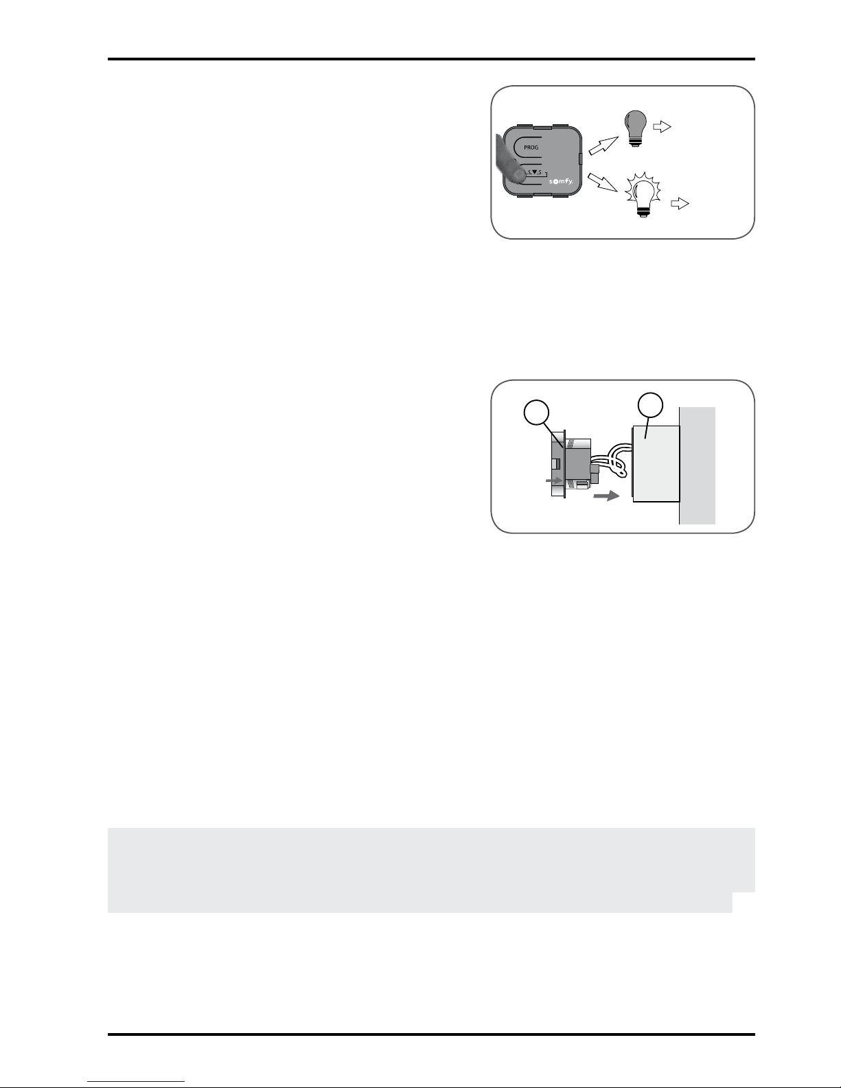
6.4.2 Programming a control point in
the Lighting Indoor RTS
Restore the mains power supply. -
Press and hold the PROG button (A) on -
the Lighting Indoor RTS:
The indicator light comes on.
►
The bulb connected to the Lighting ►
Indoor RTS comes on and then
goes off.
The Lighting Indoor RTS
►
PROG function is activated for
approximately 2 minutes.
Quickly press the PROG button (b) on
-
the control point:
The Lighting Indoor RTS indicator
►
light ashes.
The bulb connected to the Lighting
►
Indoor RTS comes on and then
goes off.
The control point is programmed
►
in the Lighting Indoor RTS.
Press the "Up" switch at the control
-
point:
If the bulb connected to the Lighting
-
Indoor RTS lights up, the Lighting
Indoor RTS works.
If the bulb connected to the Lighting
-
Indoor RTS does not light up, contact
the Somfy assistance service.
Ret the control point front cover:
-
Insert the mounting lugs into their -
notches on one side of the front
cover.
b
{
PROG
{
A
Page 16

Lighting Indoor RTS
16
Copyright © 2008 Somfy SAS. All rights reserved.
Press on the other side until it clicks, -
to x the front cover in its bracket.
Fit the cover (1) on the Lighting Indoor
-
RTS:
Place the cover on the Lighting
-
Indoor RTS so that the Somfy logo
can be seen in the bottom righthand side.
Press on the cover until a click is
-
heard: the cover is correctly tted
onto the Lighting Indoor RTS.
6.5 Timer
6.5.1 Checking the compatibility
Make sure that the mains power supply -
is off.
Remove the front cover of the original
-
control point:
Lever it with a at, pointed tool (such
-
as a athead screwdriver), without
using force, around the upper
section of the front cover to detach
it from its bracket.
The PROG button is located on
►
top of the screen and is shaped
like a tab (c).
Caution! If after removing the front cover,
no PROG button is found, this means
that the control point is not compatible:
It cannot be programmed in the Lighting
Indoor RTS.
6.5.2 Programming a control point in
the Lighting Indoor RTS
Restore the mains power supply. -
Press and hold the PROG button (A) on -
the Lighting Indoor RTS:
The indicator light comes on.
►
The bulb connected to the Lighting ►
Indoor RTS comes on and then
c
1
1
{
A
Page 17

Lighting Indoor RTS
17
Copyright © 2008 Somfy SAS. All rights reserved.
goes off.
The Lighting Indoor RTS
►
PROG function is activated for
approximately 2 minutes.
Quickly press the tab (c) on the control
-
point:
The Lighting Indoor RTS indicator
►
light ashes.
The bulb connected to the Lighting
►
Indoor RTS comes on and then
goes off.
The control point is programmed
►
in the Lighting Indoor RTS.
Press the "Up" switch at the control
-
point:
If the bulb connected to the Lighting
-
Indoor RTS lights up, the Lighting
Indoor RTS works.
If the bulb connected to the Lighting
-
Indoor RTS does not light up, contact
the Somfy assistance service.
Ret the control point front cover:
-
Insert the front cover on its bracket, -
allowing the buttons to come through
their housings.
Press the front until it clicks, to x
-
the front cover in its bracket.
Fit the cover (1) on the Lighting Indoor
-
RTS:
Place the cover on the Lighting
-
Indoor RTS so that the Somfy logo
can be seen in the bottom righthand side.
Press on the cover until a click is
-
heard: the cover is correctly tted
onto the Lighting Indoor RTS.
c
{
PROG
1
1
Page 18

Lighting Indoor RTS
18
Copyright © 2008 Somfy SAS. All rights reserved.
6.6 Situo control point
6.6.1 Accessing the PROG button on
the Situo
Remove the front cover from the Situo: -
Gently remove the front cover with a -
at, pointed tool (such as a athead
screwdriver) around the lower
section.
Lever it and lift the cover upwards,
-
without using force, to detach the
mounting lugs from the front cover.
Turn the front cover over:
-
The PROG button is located next ►
to the battery (d).
6.6.2 Programming a control point in
the Lighting Indoor RTS
Restore the mains power supply. -
Press and hold the PROG button (A) on -
the Lighting Indoor RTS:
The indicator light comes on.
►
The bulb connected to the Lighting ►
Indoor RTS comes on and then
goes off.
The Lighting Indoor RTS
►
PROG function is activated for
approximately 2 minutes.
Briey press the PROG button (d) on
-
the Situo:
The Lighting Indoor RTS indicator
►
light ashes.
The bulb connected to the Lighting
►
Indoor RTS comes on and then
goes off.
The control point is programmed
►
in the Lighting Indoor RTS.
Press the Up button on the Situo:
-
If the bulb connected to the Lighting -
d
{
PROG
{
A
Page 19

Lighting Indoor RTS
19
Copyright © 2008 Somfy SAS. All rights reserved.
Indoor RTS lights up, the Lighting
Indoor RTS works.
If the bulb connected to the Lighting
-
Indoor RTS does not light up, contact
the Somfy assistance service.
Replace the Situo front panel:
-
Insert the mounting lugs in their -
notches.
Press the lower section until it clicks,
-
to x the front cover in its bracket.
Fit the cover (1) on the Lighting Indoor
-
RTS:
Place the cover on the Lighting
-
Indoor RTS so that the Somfy logo
can be seen in the bottom righthand side.
Press on the cover until a click is
-
heard: the cover is correctly tted
onto the Lighting Indoor RTS.
6.7 Telis 1 RTS/Telis Soliris
RTS remote controls
The Telis 1 RTS has 1 indicator light (5a)
and the Telis Soliris RTS has 2 indicator
lights (5b).
If the remote control has more than
2 indicator lights, refer to the section
"Telis 4 RTS/Telis 4 Soliris RTS remote
controls".
6.7.1 Accessing the PROG button on
the Telis
Turn the Telis over: -
The PROG button (e) is located on ►
the rear panel.
1
1
5a
5b
e
Page 20

Lighting Indoor RTS
20
Copyright © 2008 Somfy SAS. All rights reserved.
6.7.2 Programming a control point in
the Lighting Indoor RTS
Restore the mains power supply. -
Press and hold the PROG button (A) on -
the Lighting Indoor RTS:
The indicator light comes on.
►
The bulb connected to the Lighting ►
Indoor RTS comes on and then
goes off.
The Lighting Indoor RTS
►
PROG function is activated for
approximately 2 minutes.
Press the PROG button (e) on the Telis
-
briey with the tip of a pencil:
The Lighting Indoor RTS indicator
►
light ashes.
The bulb connected to the Lighting
►
Indoor RTS comes on and then
goes off.
The control point is programmed
►
in the Lighting Indoor RTS.
Press the Up button on the Telis:
-
If the bulb connected to the Lighting -
Indoor RTS lights up, the Lighting
Indoor RTS works.
If the bulb connected to the Lighting
-
Indoor RTS does not light up, contact
the Somfy assistance service.
Fit the cover (1) on the Lighting Indoor
-
RTS:
Place the cover on the Lighting
-
Indoor RTS so that the Somfy logo
can be seen in the bottom righthand side.
Press on the cover until a click is
-
heard: the cover is correctly tted
onto the Lighting Indoor RTS.
e
{
PROG
1
1
{
A
Page 21

Lighting Indoor RTS
21
Copyright © 2008 Somfy SAS. All rights reserved.
6.8 Telis 4 RTS/Telis 4 Soliris
RTS remote controls
The Telis 4 RTS (6a) and Telis 4 Soliris
RTS (6b) have 4 indicator lights.
6.8.1 Accessing the PROG button on
the Telis
On the Telis, select the indicator light -
which will control the bulb connected to
the Lighting Indoor RTS, using button
(f).
Turn the Telis over:
-
The PROG button (g) is located on ►
the rear panel.
6.8.2 Programming a control point in
the Lighting Indoor RTS
Restore the mains power supply. -
Press and hold the PROG button (A) on -
the Lighting Indoor RTS:
The indicator light comes on.
►
The bulb connected to the Lighting ►
Indoor RTS comes on and then
goes off.
The Lighting Indoor RTS
►
PROG function is activated for
approximately 2 minutes.
On the Telis, select the indicator light
-
which will control the bulb connected to
the Lighting Indoor RTS, using button
(f).
Press the PROG button (g) on the Telis
-
briey with the tip of a pencil:
The Lighting Indoor RTS indicator
►
light ashes.
The bulb connected to the Lighting
►
Indoor RTS comes on and then
goes off.
The control point is programmed
►
g
f
{
PROG
6a
6b
f
g
{
A
Page 22

Lighting Indoor RTS
22
Copyright © 2008 Somfy SAS. All rights reserved.
in the Lighting Indoor RTS.
Press the Up button on the Telis:
-
If the bulb connected to the Lighting -
Indoor RTS lights up, the Lighting
Indoor RTS works.
If the bulb connected to the Lighting
-
Indoor RTS does not light up, contact
the Somfy assistance service.
Fit the cover (1) on the Lighting Indoor
-
RTS:
Place the cover on the Lighting
-
Indoor RTS so that the Somfy logo
can be seen in the bottom righthand side.
Press on the cover until a click is
-
heard: the cover is correctly tted
onto the Lighting Indoor RTS.
7. Replacing a lost or broken control point
If the control point programmed in the Lighting Indoor RTS is lost or
broken, another RTS control point must be programmed in order to
switch the bulb connected to the Lighting Indoor RTS on and off.
CAUTION! no more than 12 control points can be recorded in a Lighting
Indoor RTS.
Take another control point which is compatible with the Lighting Indoor
-
RTS.
Follow the steps described in the section "Programming the control
-
point in the Lighting Indoor RTS" according to the control point model.
Note: If after following this operation the indicator light on the Lighting
Indoor RTS does not light up, contact Somfy assistance service for
advice on replacement.
8. Everyday use of the Lighting Indoor RTS
8.1 Operating
The lighting operation differs according to the control point connected to
the Lighting Indoor RTS.
There are three categories of control point:
-
One-touch point;•
1
1
Page 23

Lighting Indoor RTS
23
Copyright © 2008 Somfy SAS. All rights reserved.
Telis 4 RTS and Telis 4 Soliris RTS •
remote controls;
Other RTS control points: Point with •
Up/STOP/Down buttons, Timer, Situo
wall-mounted control point, Telis 1 RTS
and Telis Soliris RTS remote controls.
8.1.1 Operation using a One-touch
point
Press the button on the One-touch -
point to switch the bulb connected to
the Lighting Indoor RTS on and off:
On/Off/On/Off/On etc.
►
8.1.2 Operation using a Telis 4 RTS
or Telis 4 Soliris RTS remote
control
On the remote control, use button (f) to -
select the indicator light which controls
the bulb connected to the Lighting
Indoor RTS.
To switch the bulb on:
Press the Up button:
-
To switch the bulb off:
Press the Down button:
-
8.1.3 Operation with other RTS
control points
To switch the bulb on:
Press the Up button:
-
To switch the bulb off:
Press the Down button:
-
8.2 Maintenance
Clean the Lighting Indoor RTS with -
a damp cloth using multipurpose
household or glass cleaning product.
Never immerse or soak the Lighting
-
Indoor RTS in any liquid.
f
Page 24

Lighting Indoor RTS
24
Copyright © 2008 Somfy SAS. All rights reserved.
9. Problems with the Lighting Indoor RTS?
Problem Possible causes Solutions
The Lighting Indoor
RTS indicator light
does not come on.
The Lighting Indoor
RTS wiring is
incorrect.
Switch off the power supply
and check the wiring – see
section 5 "Mounting the
Lighting Indoor RTS".
The power supply
is off.
Restore the mains power
supply.
The Lighting Indoor
RTS fuse has
blown.
Change the fuse – see section
10 "Changing the fuse".
The Lighting Indoor
RTS cannot be used
after following the
procedure step by
step.
The control point
has not been
successfully
programmed on the
Lighting Indoor RTS.
Contact the Somfy assistance
service.
The bulb connected
to the Lighting Indoor
RTS does not come
on or go off after
briey pressing the
corresponding button
on the control point.
The control point
is too far away
from the Lighting
Indoor RTS.
Bring the Lighting Indoor
RTS closer and try pressing
a button on the control point
again. If it still does not work,
replace the control point
battery.
The control point
battery is at.
Replace the battery with
a battery with the same
specications – refer to the
control point guide.
The bulb has blown. Switch off the power supply
and replace the faulty bulb
with a new bulb. Restore the
mains power supply.
Page 25

Lighting Indoor RTS
25
Copyright © 2008 Somfy SAS. All rights reserved.
Problem Possible causes Solutions
The bulb connected
to the Lighting Indoor
RTS comes on after
pressing the Down
button on the control
point.
The bulb connected
to the Lighting Indoor
RTS goes off after
pressing the Up button
on the control point.
The remote control
is being held the
wrong way round.
Turn the remote control
around so that the indicator
light is below the Up/my/
Down buttons.
The control point is
mounted the wrong
way round.
Disassemble the control
point and ret it the other way
round.
The control point
switches another bulb
on or off.
There has been
a problem when
programming the
control point in the
Lighting Indoor RTS.
Contact the Somfy assistance
service.
For any problems or unresolved -
questions, please contact the Somfy
assistance service on the number given
on the back cover of this guide.
10. Changing the fuse
Environment! Do not dispose of the
used fuse with household waste, see
paragraph 2.3.
Cut off the mains power supply.
-
Remove the cover (1) from the Lighting -
Indoor RTS:
Gently remove the cover using a
-
at, pointed tool (such as a athead
screwdriver) on one of the sides,
around the notch.
Lever it and lift the cover upwards,
-
without using force, to detach the
mounting lugs from the cover.
Remove the Lighting Indoor RTS (2)
-
1
2
Page 26

Lighting Indoor RTS
26
Copyright © 2008 Somfy SAS. All rights reserved.
from the frame (or the surface mounting
housing) without pulling on the supply
cables.
The fuse is located in the removable
►
fuse-holder which shows the fuse
part numbers.
Remove the removable fuse-holder
-
using a athead screwdriver:
Gently remove the removable fuse-
-
holder using a at, pointed tool
(such as a athead screwdriver)
around the notch on the edge of the
rounded side.
Gently lever it to detach the
-
mounting lug on the other side of the
removable fuse-holder.
Remove the fuse from the fuse-holder
-
by pushing it out of the retaining
bracket.
Insert a fuse of the same speci-
-
cations.
Replace the fuse-holder on the Lighting
-
Indoor RTS:
Insert the mounting lug in its notch.
-
Slide the other end into the notch. -
Press on the rounded end until the -
fuse-holder clicks into the Lighting
Indoor RTS.
Make sure that power supply cables are
-
always connected:
Otherwise ret the wires in the
-
corresponding wires - see section 5
"Mounting the Lighting Indoor RTS".
Insert the Lighting Indoor RTS into the
-
bracket.
Ret the Lighting Indoor RTS so that
-
"PROG" can be read.
Press the Lighting Indoor RTS until
-
a click is heard: the Lighting Indoor
Page 27

Lighting Indoor RTS
27
Copyright © 2008 Somfy SAS. All rights reserved.
RTS is correctly tted into the
bracket .
Restore the mains power supply.
-
Check that the fuse works correctly: -
Press the Lighting Indoor RTS -
control button.
If the bulb connected to the
►
Lighting Indoor RTS does not light
up, see section 9 "Problems with
the Lighting Indoor RTS?".
If the bulb connected to the
►
Lighting Indoor RTS lights up, then
the new fuse is correct.
Ret the cover (1) on the Lighting
-
Indoor RTS:
Place the cover on the Lighting
-
Indoor RTS so that the Somfy logo
can be seen in the bottom righthand side.
Press on the cover until a click is
-
heard: the cover is correctly tted
onto the Lighting Indoor RTS.
1
1
OK
Section 9
Page 28

Australia
Somfy PTY LTD
Tel: +61 (0)2 9638 0744
Website: www.somfy.com/au/index.cfm
Canada
Somfy ULC
Tel: +1 (0) 905 564 6446
Website: www.somfy.com/nam/index.
cfm?language=en-us
United Kingdom
Somfy LTD
Tel: +44 (0) 113 391 3030
Website: www.somfy.co.uk/
United States of America
Somfy Systems Inc.
Tel: +1 (0) 609 395 1300
Website: www.somfy.com/nam/index.
cfm?language=en-us
Where to nd us
Somfy SAS, with capital of 20,000,000 Euros, RCS Bonneville 303.970.230 - 08/2008
Somfy hereby declares that this product conforms to the essential
requirements and other relevant provisions of Directive 1999/5/CE. A
Declaration of Conformity is available at www.somfy.com/ce.
For use in the European Union, the Swiss Confederation (Switzerland)
and Norway.
Photos are not contractually binding
 Loading...