

SOMFY KNX IP LineMaster, 9018249B Operation And Installation Manual
©2017 SOMFY ACTIVITÉS SA, 50 avenue du Nouveau Monde, 74300 Cluses, France REF. 5135987B – 2017-06-30 Page 1/8
Operation and installation manual
KNX IP LineMaster
Ref. 9018249B
KNX Power supply with integrated KNX IP Router and diagnosis functions
KNX IP LineMaster
Application
The KNX LineMaster combines the essential functions of a KNX
bus line: Power supply with choke, KNX IP Router and KNX IP
Interface with a small footprint of only 6 units (108 mm).
The KNX IP Router in the KNX IP LineMaster allows forwarding
of telegrams between different lines through a LAN (IP) as a fast
backbone. In addition this device is suited to connect a PC to the
KNX network e.g. for ETS® programming.
The IP address can be obtained by a DHCP server, by manual
configuration via the device menue or by downloading a configured ETS application. This device works according to the
KNXnet/IP specification using the core, the device management,
the tunneling and the routing part.
The KNX IP LineMaster has a filter table (8 kByte) and is able to
buffer up to 150 telegrams.
An easy to read OLED display on the front panel enables the
user to display the operating parameters locally on the device.
Coupler function (KNXnet/IP Routing)
The KNX IP LineMaster operates as a line or backbone coupler.
In both cases, the LAN (IP) is used as a backbone.
The following table shows the application possibilities of the KNX
IP LineMaster compared to the classic topology:
Classical
Topology
(without IP)
IP coupling
of areas
(IP area coupl.)
IP coupling
of lines
(IP line coupler)
Area
(Backbone)
TP IP IP
Coupling
KNX Line Coupler
(max. 15 Pcs.)
KNX IP Router
(max. 15 Pcs.)
Directly via
LAN Switch
Main line
TP TP IP
Coupling
KNX Line Coupler
(max. 15x15 Pcs.)
KNX Line Coupler
(max. 15x15 Pcs.)
KNX IP Router
(max. 225 Pcs..)
Line
TP TP TP
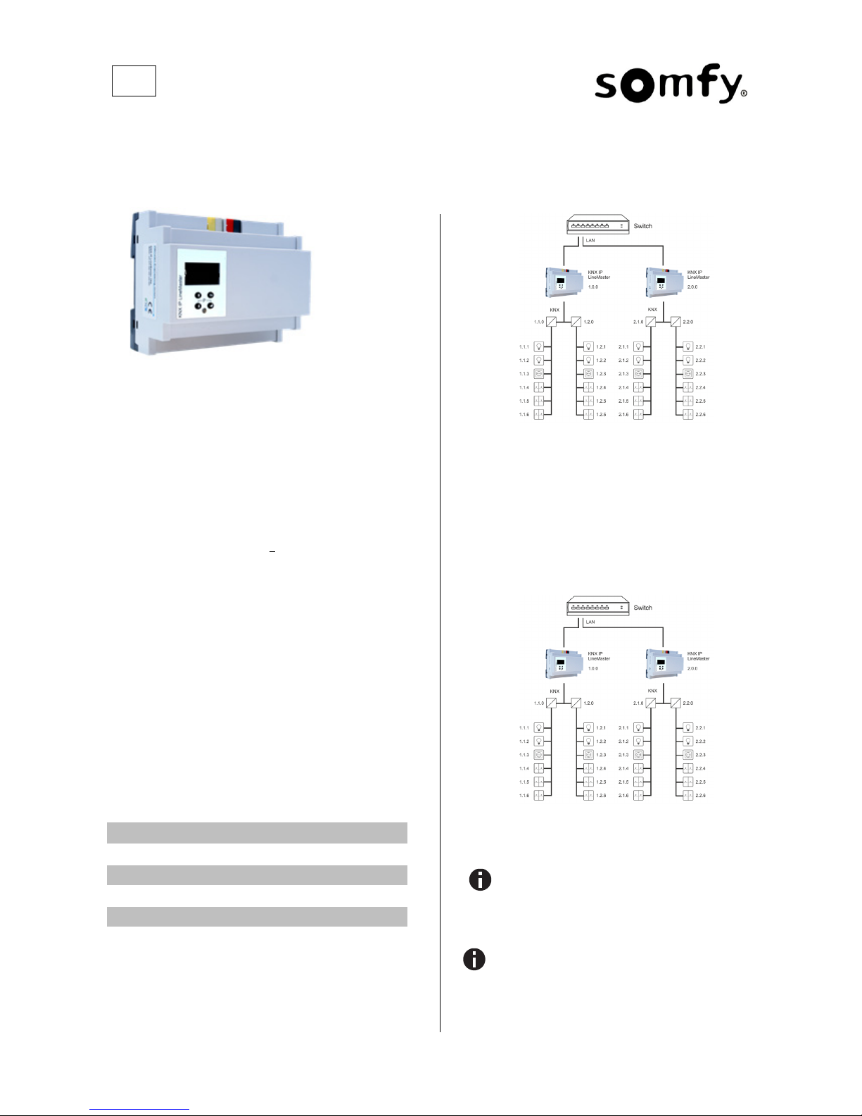
KNX IP LineMaster as line coupler
The individual address assigned to the KNX IP LineMaster determines whether the device operates as a line or area coupler. If
the individual address is in the form of x.y.0 (x, y: 1..15), the KNX
IP LineMaster operates as a line coupler. If it is in the form of
x.0.0 (x: 1..15), the KNX IP LineMaster acts as a backbone
coupler.
KNX IP LineMaster as area coupler
If the KNX IP LineMaster is used as an area coupler
(x.0.0), there must not be a KNX IP Router in the topology beneath it. For example, if a KNX IP Router has the
individual address 1.0.0, there must be no KNX IP Router with the address 1.1.0.
If the KNX IP LineMaster is used as a line coupler
(x.y.0), there must not be a KNX IP Router in the topology above it. For example, if a KNX IP Router has the individual address 1.1.0, there must be no KNX IP Router
with the address 1.0.0.
EN
©2017 SOMFY ACTIVITÉS SA, 50 avenue du Nouveau Monde, 74300 Cluses, France REF. 5135987B – 2017-06-30 Page 2/8
KNX IP LineMaster as area and line coupler
The KNX IP LineMaster has a filter table and thus contributes to
reducing the bus load. The filter table (8kB) supports the extended group address range and is automatically generated by the
ETS.
Because of the speed difference between the Ethernet (100
Mbit/s) and KNX TP (9.6 kbit/s), a far greater number of telegrams can be transmitted on IP. If several consecutive telegrams
are transmitted for the same line, they must be buffered in the
router to avoid telegram loss. The KNX IP LineMaster has a
memory for 150 telegrams (from IP to KNX).
Bus access function (KNXnet/IP Tunneling)
The KNX IP LineMaster can be used as an interface to KNX. The
KNX bus can be accessed from any point in the LAN. The device
supports up to 6 simultaneous Tunneling connections. For each
connection an additional individual address must be assigned.
This is described in the following sections.
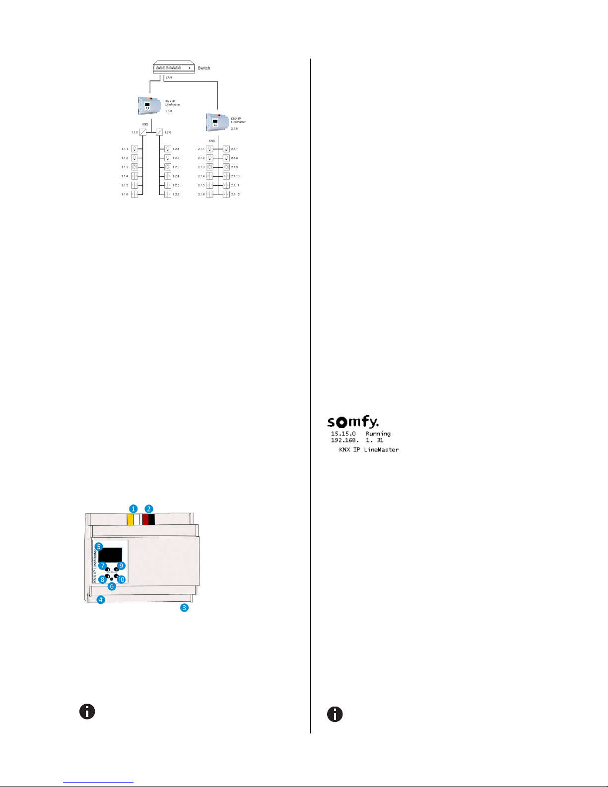
Installation and Connection
The KNX IP LineMaster is designed for installation on DIN rail
with a width of 6 units (108 mm). It features the following controls
(❼❽❾❿) and displays (❺
❻):
Settings
The settings of the device can be accessed via
1. Local display on the device (partly)
2. ETS (Version 4.2 or higher)
The KNX Programming Mode is activated/deactivated by
simultaneously pressing the buttons ❽❿ – when activated the programming LED
❻ lights up.
Programming and status LED ❻
The red LED on the front panel is used to display the KNX programming mode and errors. The LED can have the following
states:
LED off: The programming mode is not active and
there is no error (normal operating mode).
LED lights up: The programming mode is active,
any errors are not visualized/notified by the LED,
but can be read on the display.
LED flashes quickly: The programming mode is
not active. The rapid flashing indicates one of the
following faults:
o Overload (sum of the current of auxiliary
and Bus power)
o The device is not loaded correctly, for
example, a cancelled download.
Factory default settings
The following configuration is set by factory default:
Individual device address: 15.15.0
Number of configured KNXnet/IP tunneling con.: 6
Individual address of tunneling con. 1: 15.15.240
Individual address of tunneling con. 2: 15.15.241
Individual address of tunneling con. 3: 15.15.242
Individual address of tunneling con. 4: 15.15.243
Individual address of tunneling con. 5: 15.15.244
Individual address of tunneling con. 6: 15.15.245
IP address assignment: DHCP
Direct Setting via display on device
A. Startup and idle display
During startup of the device, the physical
address and the status of the application
is displayed.
The device name “KNX IP LineMaster”
can be changed within ETS parameter
settings.
The status can be one of the following values:
Running: Application is loaded and running
Stopped: The application is stopped -
❻ LED for
Programming Mode is flashing
Unloaded: The application is not loaded-
❻ LED
for Programming Mode is flashing
Loading: The application is currently loading by
ETS
Overload: The output current is above the limit of
900mA -
❻ LED for Programming Mode is flash-
ing
Manual:
Parameterized coupler settings were
manually overwritten (filter, repetition and
acknowledge) via the manual operation in the device display. By pressing long on on Enter ❿, the
normal operating mode, as parameterized, is restored.
The power supply functionality (KNX and auxiliary voltage) is
not dependent whether the application is running or not.
After 10 minutes of inactivity the display will turn into
screensaver mode (blank screen with a bouncing dot) to
safe display life time. Press any key to turn the display
on again.
❶ Aux. Power Out 30 V DC
❷ KNX Bus Out
❸ Power In 230 V AC
❹ LAN Connector
❺ OLED Display
❻ LED for Prog. Mode
❼ Up Button
❽ Down Button
❾ Escape Button
❿ Enter Button
©2017 SOMFY ACTIVITÉS SA, 50 avenue du Nouveau Monde, 74300 Cluses, France REF. 5135987B – 2017-06-30 Page 3/8
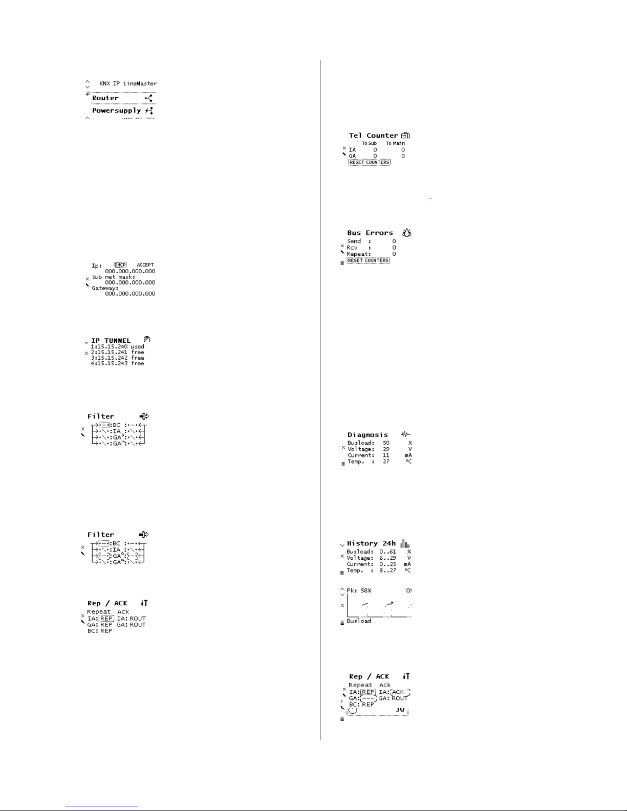
B. Main Menu
By pressing ❽ (arrow down) you enter
the main menu of the device. By pressing ❿ (enter) you enter the submenus.
Within the menus you can use ❼ (arrow
up) and ❽ (arrow down) for navigation;
❿ (enter) is for confirmation and ❾
(escape) is to cancel / go back / one level higher.
Router <-> Powersupply <-> System Info <-> Dev Reset <->
Contrast
C. Submenu Router
The Router menu item offers the following submenus:
IP Config <-> IP Tunnel <-> Filter <-> Rep / ACK <-> Tel
Counter <-> Bus Errors
D. Submenu IP Config
Select DHCP or Manual for IP configuration. Within Manual you can set the IP,
subnet and gateway. Use ❼ and ❽ to
navigate/set and ❿ to select.
E. Submenu IP Tunnel
The KNX IP LineMaster supports 6 simultaneous KNXnet/IP tunneling connections. You can display them in the submenu IP Tunnel including their actual
status as well as the corresponding individual address.
F. Submenu Filter
For commissioning or test purposes,
the filter settings parameterized by the
ETS can be bypassed temporarily. The
settings for broadcast telegrams (BC),
individually addressed telegrams (IA)
and group telegrams (main groups 0 to
13 GA
0
and main groups 14 to 31 GA14)
can be changed separately. The lefthand side relates to the forwarding from
the main (IP) to the subline (TP), the
right-hand side to the forwarding from
the sub (TP) to the main line (IP). The
following options are available: - Forward, x Block and \ Filter.
Settings differing from parameterization
are marked with an angular bracket.
The parameterized setting can be restored with a long press on Enter ❿.
G. Submenu Rep / ACK
In this submenu, the settings for repeating telegrams on the subline (TP) can be
changed. The settings for broadcast telegrams (BC), individually addressed telegrams (IA) and group telegrams (GA)
can be changed separately: --- no repetition, REP up to 3 repetitions.
In addition, the settings for the telegram
acknowledge can be changed on the
subline (TP): ROUT Acknowledge only
when forwarding, ACK acknowledge always, NACK negative acknowledgment.
When answering with NACK, access to
the device via KNX TP is no longer possible, see ETS parameter settings.
These settings are temporary.
Settings differing from parameterization
are marked with an angular bracket. The
parameterized setting can be restored
with a long press on Enter ❿.
H. Tel Counter
This submenu contains telegram counters. The number of forwarded telegrams
is displayed here, separated from the direction (mainline IP to subline TP and
vice versa) and telegram type (individually addressed telegrams IA and group
telegrams GA). The counters can be reset here.
I. Submenu Bus Errors
In this submenu, you can display bus
errors and reset the bus error counters
by pressing ❿ (enter).
The following errors are counted:
Send errors: Send failed after final repetition due to
missing ACK, NACK or BUSY.
Receive errors: Malformed telegrams or telegram
fragments received.
Repetitions: Number of received repeated tele-
grams. Also own repetitions are counted.
J. Submenu Submenu Powersupply
The Powersupply menu item offers the following submenus:
Diagnosis <-> History <-> Bus Reset <-> Event Counters
K. Submenu Diagnosis
This submenu shows actual values of
busload (%), voltage (V), current (mA),
and temperature (°C).
The busload is an indication of number
of telegrams in a time span.
A value of 100 % busload is achieved by about 50 telegrams
per second (Group Value Write, 1 Byte data). Voltage is the
bus voltage, current the sum of bus and auxiliary current.
The temperature is measured within the device.
L. Submenu History
History displays the value range (min
and max) for busload, voltage, current
and temperature over the last 24 hours.
By pressing the ❽ (arrow down) several
times a graphical ‘realtime' visualization
is displayed: for busload, voltage, current, and temperature. To go back to the
main menu, press ❾ (escape).
The time span of each graph is approximately 2 minutes.
M. Submenu Bus Reset
This submenu allows you to reset the
KNX Bus line. Press ❿ (enter) to switch
off the KNX voltage. The default reset
time is 30 seconds. To stop the countdown, press ❾ (escape)
 Loading...