

Page 1

270°
Rotating
Camera
USER MANUAL
DVR-2HD
Vehicle Drive Recorder
Page 2

2
Getting Started
Product Features 3
Safety Warnings and Precautions 5
What’s included 12
1. Introduction to Product
Snooper DVR-2HD 13
Name and Function of Each Part of Mounting Kit 15
2. Installation
Pre-Installation Notice 16
Snooper installation 17
3. How to Use the Product
Power Connection and Continuous Recording 20
Event (Shock) Recording 20
Voice Recording ON/OFF 21
Speaker/Guiding Comment ON/OFF 21
Parking Mode 22
System Initialization 23
Explanation of LED Status and Buzzer Sound 24
How to Remove microSD Memory Card 25
4. Using the Snooper Viewer
Program Installation 26
Running Program 27
Snooper Viewer 28
Control of Snooper Viewer 29
Fetching Recorded Image Data 31
Checking Driving Route (GPS) 31
Other Operation Functions 32
Setting Program 33
Setting Time 34
GMT Setting (Time Zone) 35
Firmware Upgrade 36
5. Product Specications & Product Certication
Process
Product Specifications 37
6. Troubleshooting 39
Page 3

3
Product Features
HD Images
• 1280X720 (HD)
• Codec : H.264
Voice Guidance supported
• Voice guidance function for user’s convenience
High Sensitivity GPS Receiver
• The information about the location, velocity
and routing that is obtained from the GPS is
indicated on Google Maps®.
Wide Angle of View
• 130° viewing angle
Security LED
• Security LED activation in Parking Mode.
270° Camera Rotation
• Vehicle Cabin Viewing is also possible.
Parking Mode
• Activated by motion or shock user selectable.
Battery Drain Prevention
• For extended Parking Surveillance.
200 만 화소
전방 : 1280 x 720(HD)
후방 : 640 x 480
영상 압축 : H.264
Google Map에 표시
270
°
270
°
200 만 화소
전방 : 1280 x 720(HD)
후방 : 640 x 480
영상 압축 : H.264
Full- Touch LCD
2.4 인치 터치 LCD를 통한
편리한 기능 사용
주차 감시 모드
주차 중 움직임 및 충격이
감지되는 경우 녹화
(모션디텍션)
Google Map에 표시
270
°
200 만 화소
전방 : 1280 x 720(HD)
후방 : 640 x 480
영상 압축 : H.264
Full- Touch LCD
2.4 인치 터치 LCD를 통한
편리한 기능 사용
Google Map에 표시
270
°
200 만 화소
전방 : 1280 x 720(HD)
후방 : 640 x 480
영상 압축 : H.264
Full- Touch LCD
2.4 인치 터치 LCD를 통한
편리한 기능 사용
Google Map에 표시
Page 4
4
Main Functions of Product
ACC OFF
120 도 시야각
3G 충격 센서
차량에 과도한 충격이
가해지는 경우 자동 녹화
주차 감시 모드
주차 중 움직임 및 충격이
감지되는 경우 녹화
(모션디텍션)
주차 감시 모드
주차 중 움직임 및 충격이
감지되는 경우 녹화
(모션디텍션)
SD ca rd 포맷
제품에서 SD ca rd를
바로 포맷
SD ca rd
제품에서 SD ca
바로 포맷
ACC OFF
주차 감시 모드
주차 중 움직임 및 충격이
감지되는 경우 녹화
(모션디텍션)
SD ca rd 포맷
제품에서 SD ca rd를
바로 포맷
SD ca rd
제품에서 SD ca
바로 포맷
SD ca rd
제품에서 SD ca
바로 포맷
SD ca rd
제품에서 SD ca
바로 포맷
ACC OFF
주차 감시 모드
주차 중 움직임 및 충격이
감지되는 경우 녹화
(모션디텍션)
SD ca rd 포맷
제품에서 SD ca rd를
바로 포맷
SD ca rd
제품에서 SD ca
바로 포맷
ACC OFF
120 도 시야각
3G 충격 센서
차량에 과도한 충격이
가해지는 경우 자동 녹화
주차 감시 모드
주차 중 움직임 및 충격이
감지되는 경우 녹화
(모션디텍션)
주차 감시 모드
주차 중 움직임 및 충격이
감지되는 경우 녹화
(모션디텍션)
SD ca rd 포맷
제품에서 SD ca rd를
바로 포맷
SD ca rd
제품에서 SD ca
바로 포맷
ACC OFF
SD ca rd 포맷
제품에서 SD ca rd를
바로 포맷
SD ca rd
제품에서 SD ca
바로 포맷
ACC OFF
120 도 시야각
3G 충격 센서
차량에 과도한 충격이
가해지는 경우 자동 녹화
주차 감시 모드
주차 중 움직임 및 충격이
감지되는 경우 녹화
(모션디텍션)
주차 감시 모드
주차 중 움직임 및 충격이
감지되는 경우 녹화
(모션디텍션)
SD ca rd 포맷
제품에서 SD ca rd를
바로 포맷
SD ca rd
제품에서 SD ca
바로 포맷
ACC OFF
ACC OFF
120 도 시야각
주차 감시 모드
주차 중 움직임 및 충격이
감지되는 경우 녹화
주차 감시 모드
주차 중 움직임 및 충격이
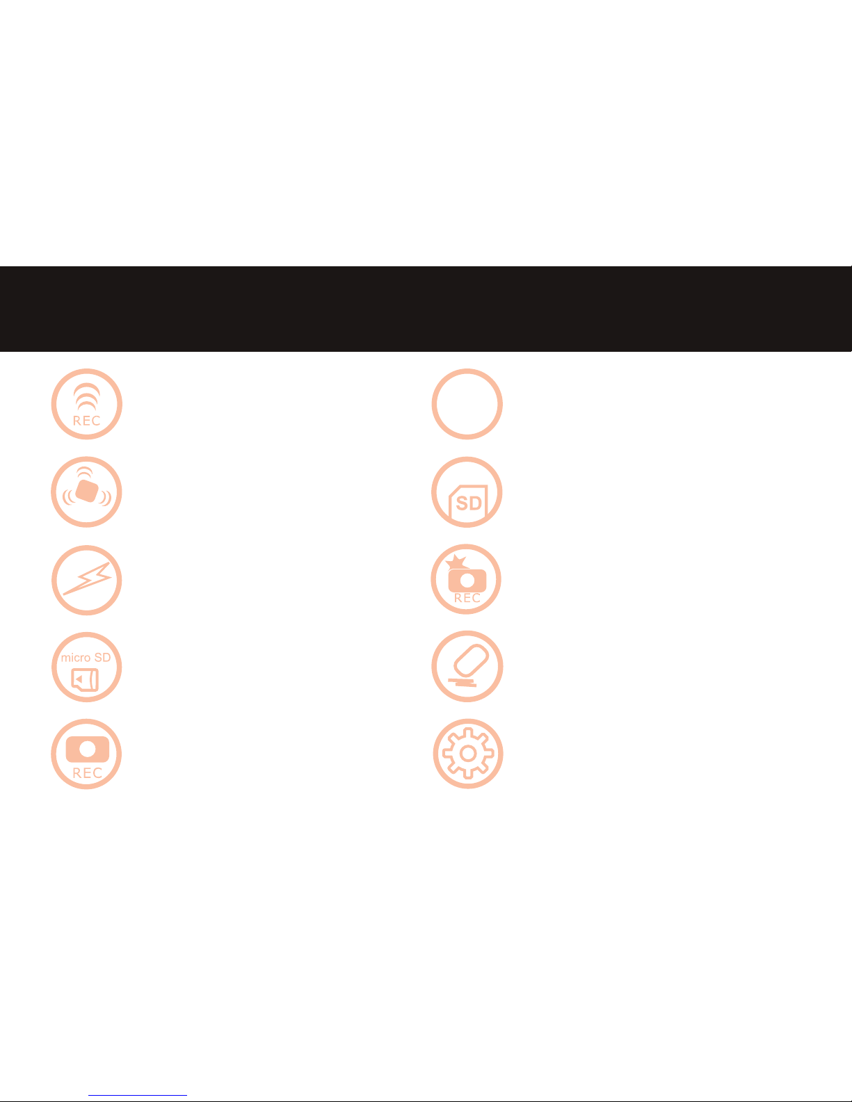
Voice Recording “ON / OFF”
• Privacy Protection
• “ON/OFF” Status Indicator LED
3-Phase Continuous Power Supply
• When the car is o, the parking mode begins
automatically.
3-Axis Acceleration Sensor
• In case where excessive shocks occur to car,
the 3-axis acceleration sensor automatically
records the images.
microSD Memory card format
• The microSD memory card format is
implemented in the product itself.
12V-24V Power
Shock (Event) Recording
Upgrade through
microSD Memory Card
Sequential Deletion of
Recorded Images
Continuous Recording Function Setting
Page 5

5
Before You Start
• This product is a road safety accessory and the manufacturer is not liable for any losses brought on by malfunctions,
loss of data or any other forms of losses from using this product.
• This product is an accessory designed for the specic purpose of recording and saving captured video footage of
the areas near the vehicle. Certain functions may not be supported depending on the driving conditions and vehicle
conditions. The rmware updates for improving performance may result in dierent performance by each product.
The video may not be recorded depending on the conditions in which the device is used. Please use the device only
for your reference. The recording may not take place depending on the status of the microSD card.
• This device is designed to capture and save accident footages of the vehicle in which the product is installed in.
However, it does not guarantee that every accident footage will be recorded. Accidents with very minor level of
impact may not activate the impact sensor and the accident may not be recorded as an event footage.
• In vehicles that use smart keys, the batteries may discharge while in Parking Mode.
Scope of Warranty and Liabilities
Before reading the user manual, rst check the following information
Page 6

6
Safety Warnings and Precautions
Please read the following safety information carefully. The information is provided to prevent potential injury or damage.
Do not operate the product while driving.
Do not disassemble, repair, or modify the product.
This may cause fire,electric shock, there are no user
servicable parts inside the device.
Do not cover or place anything on the product.
This may cause the product to overheat and cause
premature failure of components.
If the unit ceases to operate, unplug the device and
contact your Snooper Technical on 01928 579579.
Warning
Warning
Failure to follow these safety warnings could
lead to a serious injury or death.
Caution
Failure to follow these cautions could lead to
an injury or cause loss of property.
Classication (Degree of Danger)
Page 7
7
Safety Warnings and Precautions
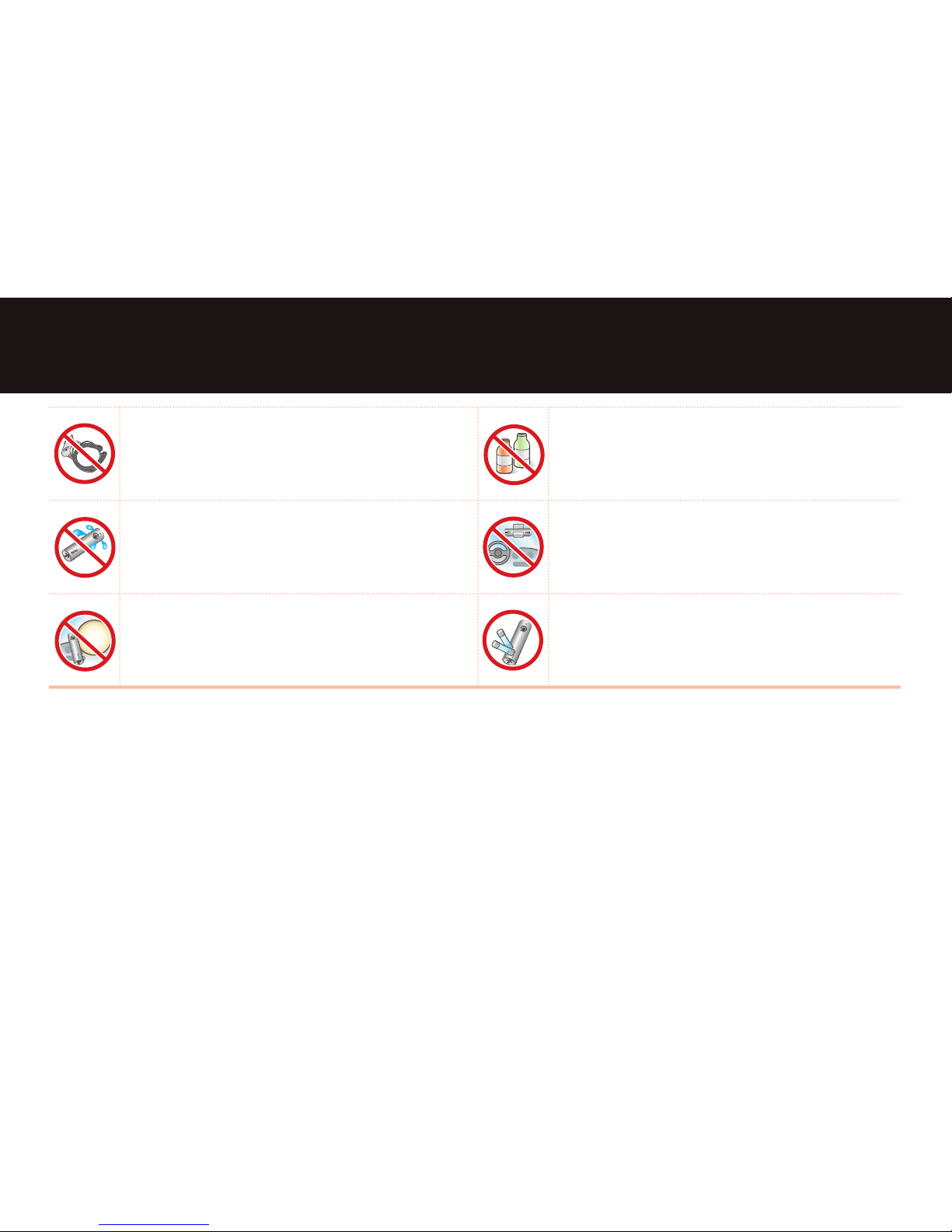
Use only the supplied power cable and windscreen
bracket.
Do not modify the supplied power cable and/or
windscreen bracket.
Do not expose the device to liquids.
Do not install the product in an area which is
susceptible to moisture or dust.
Do not install product where it will obstruct your
eld of vision.
Do not install the device an an area which may aect
the safe operation of the vehicle controls or safety
equipment e.g area where Air Bags may be deployed.
The environmental temperature should not exceed
the following limits (32°F to 122°F) , (0°C to 50°C) and
keep the device away from high humidity.
Page 8
8
Safety Warnings and Precautions
SanDisk
4GB
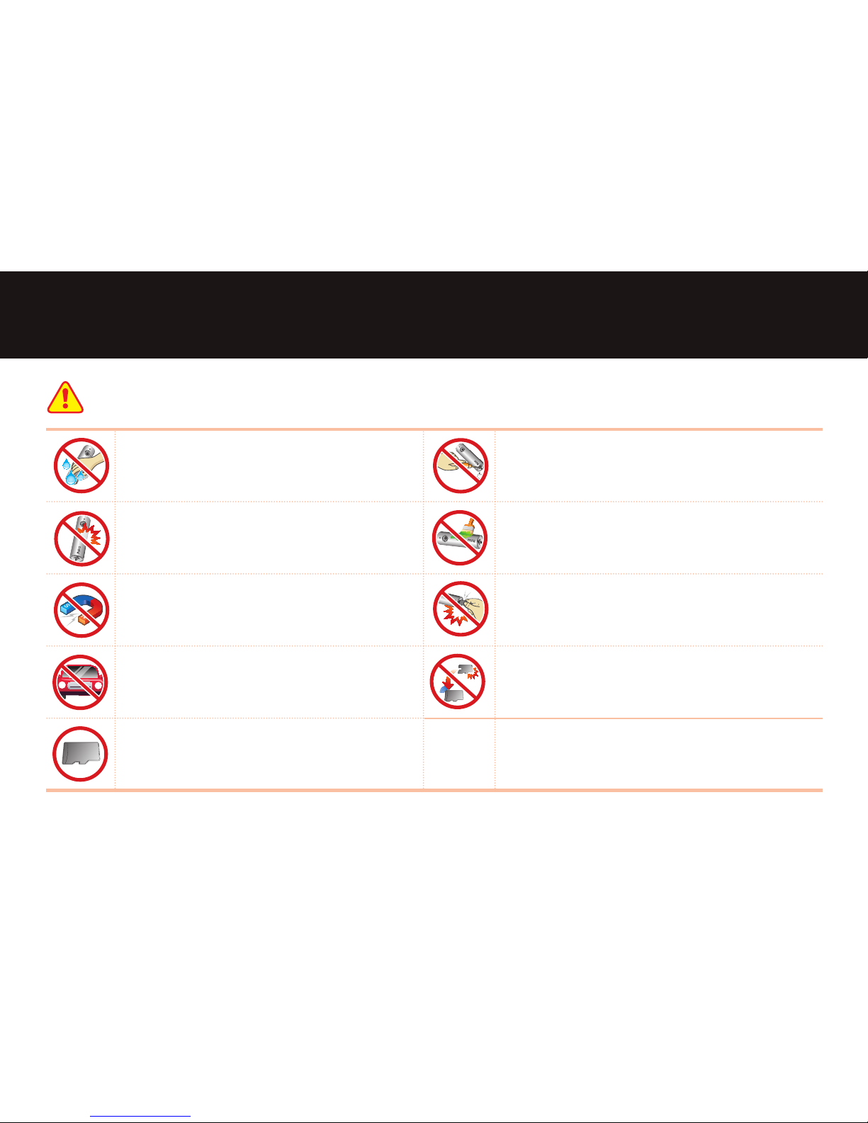
Do not touch the device with greasy or wet hands.
Do not use a sharp object to operate the buttons.
SanDisk
4GB
Do not drop device.
Do not attach any stickers or paint on the device or
memory card.
This can damage the product or lead to a product
breakdown.
Do not place the device near a magnet or areas of
high magnetic elds.
SanDisk
4GB
Do not take the micro SD memory card out during
operation.
This can damage the product and any data on the micro
SD memory card.
SanDisk
4GB
SanDisk
4GB
Do not place the device behind the shaded area
of the windscreen as this will aect the image
quality.
SanDisk
4GB
SanDisk
4GB
SanDisk
4GB
SanDisk
4GB
SanDisk
4GB
Replace old Micro SD memory cards.
Prolonged usage of an old micro SD memory card can
lead to data loss.
SanDisk
4GB
Use only approved Snooper micro SD memory
cards.
Caution
Page 9

9
Safety Warnings and Precautions
Data Loss/Corruption (microSD Card Care)
Damage to the microSD card can result in data corruption or loss.
• microSD card is a highly sensitive piece of technology that can become defective due to changes in external
environment or severe impact. Protect the card against impact and damage.
• The manufacturer will not be held responsible in the event of microSD card damage due to user negligence or
external factors.
• We recommend using
Snooper 16GB microSD cards
Causes of microSD Card Damage and Data Corruption
• External impact during installation/uninstallation.
• Abnormal disruption in power supply, such as sudden disconnection of the power cable while the black box is in
use, can damage the microSD card.
• External impact on the product while it is in operation can also cause data corruption or damage the microSD card
itself. To minimize loss and damage brought on by microSD card damage regularly check and back up your data.
Note
Page 10

10
Safety Warnings and Precautions
Preserving Data on the micro SD Memory Card
Please pay attention to following information to minimize the possibility of losing recording data.
The manufacturer is not responsible for missing data or defects caused by the user’s mishandling.
• Protect micro SD Memory from any impact or misuse as this may cause data loss.
• Prior to the micro SD memory card replacement, check if micro SD memory card is compatible with the product.
• Properly turn o the device's power.
• Backup important data regularly.
• Format the micro SD memory card 1~2 times a month.
Estimated recording time based on the micro SD Memory Card Capacity
Manufacturer class 2 class 4 class 6 class 10 Note
Transcend
• • • •
Supports HD and SDHC
Lexar
• • • •
4GB:
4hr 30min to 5hr
4GB
8GB:
8hr 30min to 10hr
8GB
16GB Supplied:
16hr 30min to 20hr
16GB
32GB:
35hr 30min to 40hr
32GB
Page 11

11
Safety Warnings and Precautions
GPS Use
• If you are using the product for the rst time or using it after an extended period of non-use (3 days or
longer), it will take longer than usual for the GPS to determine your current location.
• GPS signal strength is susceptible to weather conditions (rain, fog, etc.) and radio wave interference.
• The ideal ambient temperature range for the GPS receiver is 0℃- 60℃/32°F -140°F. Maintain this
temperature range inside the vehicle, especially during summer and winter months.
• GPS reception may be low underneath an overpass, inside a tunnel, or with a high density of buildings
nearby.
• The GPS receiver may not function properly in vehicles with special coating or tinting on the windshield or
equipped with electro-magnetic wave-generating devices on board.
• GPS reception may be low or unavailable altogether near high-rise buildings or power cables due to the
eects of high voltage.
• With poor GPS reception, it may take longer to determine the current location if the vehicle is moving.
• Time and speed displays may not function properly in GPS shadow zones and under poor GPS reception
conditions.
Note
Page 12
12
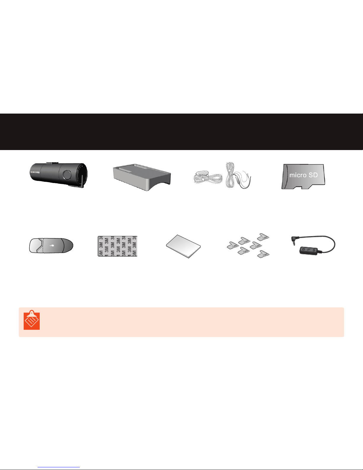
What's Included
• The images are for illustration purposes only.
• The instructions can be modied without any prior notication to the users for the improvement of product performance.
Snooper® DVR2-HD
Vehicle Drive Recorder
Mounting kit
Power Cable
(Plug-in or Hard wire)
microSD Card 16gb
(adapter included)
SD/MMC/RS-MMC
USB 2.0
microSD
memory card reader
Double-sided Tape Quick Guide Manual Cable clips GPS Antenna
4GB
Note
Page 13

13
1. Introduction to Product
Snooper DVR-2HD
• The images of these instructions can be dierent from those of real products.
• The instructions can be modied without any prior notication to the users for the improvement of product performance.
1
Camera lens To record images
2
Power input terminal
It is used to connect to the power
cable.
3
Memory card
insertion slot
It is used to insert and remove the
microSD memory card.
4
GPS input terminal
It is used to connect to the GPS
cable.
5
Speaker (Buzzer)
The voice guidance is provided
through the built-in speaker.
6
Mic button
(Short Key) Voice Recording On/O
(Long Key) microSD memory card
format
7
Speaker button
(Short Key) Speaker On/O
(Long Key) System Initialization
2
3
6
5
4
7
1
Note
Page 14

14
1. Introduction to Product
Snooper DVR-2HD
• The images of these instructions can be dierent from those of real products.
• The instructions can be modied without any prior notication to the users for the improvement of product performance.
1
Security LED
Under the parking mode, it blinks,
and while the car is parked, it is
turned on under the event/motion
recording.
2
GPS LED
The LED blinks while the GPS cable
is connected, and is turned on when
GPS signal reception begins. (Green
Colour)
3
Event LED
It’s turned on during event (shock)
recording, motion recording. (Red
Colour)
4
Power LED
While the power is connected,
it blinks. After the connection of
power, it is turned on. (Blue Colour)
5
Mic LED
The LED is turned on when the
voice recording is in “ON” status.
6
Speaker LED
The LED is turned on when the
speaker is in “ON” status.
1
6
5
3 24
Note
Page 15

15
1. Introduction to Product
Name and Function of each part of Mounting Kit
Name of Each Part Function
1
Mounting Kit Used to attach and detach the Snooper to the vehicle.
2
Fixation of Mounting Kit
Using double-coated tapes, the mounting kit can be xed on the front glass of the
inside of the car.
3
Angle Control Adjust the angle of the recorder.
1
2
3
Page 16

16
2. Installation
Precautions
Parts & Accessories
• Make sure you have all the parts and accessories before installing the DVR-2HD. ►Page 12
• If you are missing parts or accessories, contact your place of purchase.
Installation
The DVR position on the front windshield and its forward-facing angle greatly aect the video recording quality.
Follow these instructions to get the best results:
• Install the mount on the central axis of the vehicle. (Ideal position behind rearview mirror).
• Do not use the DVR without the mount.
• Do not place any item between the DVR and the front windshield or cover up the Snooper.
• Secure the mount in place using the double-sided tape. However, make sure the windshield area where you will be attaching
the mount to is free of dust and other forms of contaminants.
Page 17

17
2. Installation
Snooper DVR-2 installation
Check the general environment and the position on which the body shall be xed. For the notice regarding the
installation, please see page 5.
This device should be installed on the upper center of the windscreen if you want to get the highest image quality.
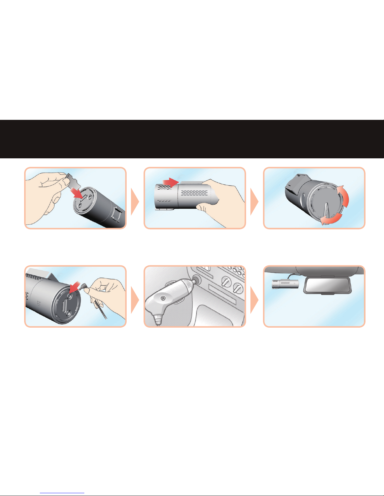
Clean the windshield. Remove the protective film from
the double-sided tape.
Attach the bracket to the windshield
(position to not obstruct the driver's view.)
1 2 3
Page 18
18
Insert the microSD card into the card slot
of the recorder.
Place the recorder into the bracket. Adjust the angle of the recorder
Use the adjustment angle to make sure
that the lens is directed centrally and in
the direction of the desired view to be
recorded.
Connect the power cable to the "PWR"
input on the recorder.
Connect the DC end of the power
cable into the car power outlet. You can
hardwire your DVR into your vehicle.
Find out more visit snooper.co.uk
Cable arrangement
Arrange the cables cleanly using a cable
holder.
2. Installation
4
7
5
8
6
9
Page 19

19
270° Rotation
When the recording of the inside of
vehicle is required, you can start the
recording after rotating the body.
2. Installation
• An alarm message appears when the microSD card is not normally recognized. (Voice message, LED)
• For the connection of continuous power supply cables (3-phase), we recommend you to refer to a qualied service center. (Black
line: GND/White line: ACC/Red line: BAT(B+))
• For the products without GPS systems, the time setting is possible through the PC Viewer.
Note
Page 20

20
3. How to Use the Product
Power Connection and Continuous Recording
Event (Shock) Recording
• When event happens, the recording mode is applied for the time of
15 sec. before and after each event. (30 sec. total)
Pre-event recording
time: 15 seconds
Post-event recording
time: 15 seconds
The moment when event happens
Sound
Guiding comments after power connection – “Please Drive Safely”
Guiding comments after boot completed - "Driving recording is beginning.”
LED
Power LED (Blue) “ON”
Sound
Guiding comments – “Now Shutting Down.”
LED
All LEDs “OFF”
Sound
Event alarming sound – “Ding-dong Ding-dong”
LED
Event LED (Red) “ON”
• The product is in “ON” status automatically when the power cable is connected.
• The product is in “OFF” status automatically when the power cable is disconnected.
• The recording mode begins automatically when shocks are perceived.
• Event recording time: when shock is perceived, the recording mode is applied for
the time of 15 sec. before and after each shock. (30 sec. total)
Note
Page 21

21
3. How to Use the Product
Voice Recording ON/OFF
SPK/Guiding Comment ON/OFF
Sound
ON Guiding comments – “Voice recording is beginning.”
OFF Guiding comments – “Voice recording is stopping.”
LED
ON MIC LED “ON”
OFF MIC LED “OFF”
Sound
ON Guiding comments – “SPK is turned on.”
OFF Guiding comments – “SPK is turned o.”
LED
ON SPK LED “ON”
OFF SPK LED “OFF”
• Press the “MIC Button” to turn on and turn o the voice recording mode.
(Initial setting: ON)
• Press the “SPK Button” to turn on and turn o the function. (Initial setting:
ON)
Page 22

22
3. How to Use the Product
Parking Mode
Sound
Guiding comments – “Parking mode is beginning.”
LED
Under the parking mode, Security LED blinks.
If Shock/Motion Recording starts with the car parked,
Security LED is turned on.
(N.B.: When the parking mode runs continuously,
Security LED continues to blink.)
Continuous Parking
Continuous Recording, Shock Recording
Motion Detection Parking (Motion)
Motion Detection Recording, Shock Recording
Shock Detection Parking
Shock Recording
Sound
Guiding comments – “Parking mode is stopping.”
LED
Security LED “OFF”
• If the continuous power is supplied, the parking mode
starts automatically even when the car is o (ACC O).
• The recording modes during parking are applied according to the values set through the Snooper only viewer.
• When the car is on (ACC on), the parking mode stops
automatically.
Page 23

23
3. How to Use the Product
System Initialisation
Button & Operation Guiding Comment LED Status
Press SPK Button for 5 seconds.
“Do you want to initialize the
system?”
MIC LED & SPK LED
Blinking
Confirmation of initialization > Press MIC
Button.
“System Initialization is
beginning.”
MIC/SPK/GPS/Event LEDs
Blinking
Cancellation of initialisation > Press SPK
Button.
“System Initialization has
been canceled.”
After the initialization is completed, the
product reboots automatically.
“The system is restarting.”
Button & Operation Guiding Comment LED Status
Press MIC Button for 5 seconds.
“Do you want to format
memory card?”
MIC LED & SPK LED
Blinking
Confirmation of format > Press MIC
Button.
“Memory card format is
beginning.”
MIC/SPK/GPS/Event LEDs
Blinking
Cancellation of format > Press SPK Button.
“Memory card format has
been cancelled.”
After the format is completed, the
product reboots automatically.
“The system is restarting.”
• Function Setting Initialization: when SPK Button is pressed for 5 seconds, System
Initialisation begins.
• microSD memory card format: when MIC Button is pressed for 5 seconds, memory card
format begins.
SPK Button
MIC Button
Page 24

24
Explanation of LED Status and Buzzer Sound
The LED status and buzzer sound of each situation are as follows:
3. How to Use the Product
Classication Situation Guiding Comment LED Status Note
GPS
GPS connection
“GPS system has been
connected.”
GPS LED Blinking GPS cable connection after boot completion
GPS signals perception No comment GPS LED “ON” Normal GPS signal perception
“GPS system has been
disconnected.”
“GPS system has been
disconnected.”
GPS LED “OFF” GPS cable removal with black box “ON”
SD card error
SD card error “Check memory card.”
MIC/SPK/GPS/
Event LEDs Blinking
microSD card not inserted, Error happened
SD card removal
“Memory card has been
removed.”
SD card removal with black box “ON”
Firmware upgrade
Firmware upgrade
“A new firmware version
is available.” -> “Firmware
update is beginning.”
Firmware upgrade through microSD card
Reboot after upgrade “The system is restarting.” Power LED Blinking Restart after firmware upgrade
Format recommendation
Periodical microSD
card formatting
(recommendation)
“Periodical microSD card format
is recommended.”
Power LED “ON”
Periodical microSD card format recommended: 1 time per
month
Discharge breaking
Discharge breaking
operation
Buzzer sound – “Beep”
Power LED Blinking
(Every 5 seconds)
The discharge breaking is carried out if the voltage falls
below the preset threshold for longer than 1 minute.-> At
restarting the car, the operation is cancelled.
High-temperature
prevention
High-temperature
prevention operation
Buzzer sound – “Beep”
Power LED Blinking
(Every 5 seconds)
The high-temperature prevention operation is performed
if the preset prevention threshold is exceeded for longer
than 10 seconds.
-> If the temperature is maintained at 25° below the
threshold for 10 seconds, the operation is cancelled
Page 25

25
3. How to Use the Product
How to Remove microSD Memory Card
• Removing the microSD card while the Snooper is turned on will cause data corruption.
1
Turn o the car and unplug the power cable from the DVR-2HD.
Remove the microSD memory card from the card insertion slot by pressing the card.
2
Note
Page 26

26
Software Installation
The user can playback recorded video through the video player with a compatible computer. Windows XP, Vista and 7.
SanDisk
4GB
SD/MMC/RS-MMC
USB2.0
1
Connect the SD memory
card to a computer.
- Combine the SD
memory card with USB
gender and connect
the USB gender to a
computer.
2
Double-click
snooper.exe on the
micro SD memory
card or download the
latest program from the
download menu at
www.snooperneo.co.uk
3
Designate an installation
folder for the software
and then click the ‘Install’
button.
4
After the installation
is completed, click the
‘Close’ button.
• M
ake sure insert you the correct side of micro SD memory card to the USB gender.
• The Classic View can now be executed from the installation location or the desktop.
4. Using the Snooper Viewer
Note
Page 27

27
Running Program
4. Using the Snooper Viewer
SanDisk
4GB
SD/MMC/RS-MMC
USB2.0
►
1
Connecting the microSD memory card to the computer
Insert the microSD card into the USB gender and then connect it to the
USB terminal of the computer.
2
Running Program
Run the launcher program clicking the program icon of the
background.
3
The launcher program runs on the computer.
• While inserting the microSD card into the USB gender, check whether the front and rear directions of the card are accurate.
• The viewer and launcher program are coupled to each other while running.
Snooper Suite
Note
Note
Page 28

28
Snooper Viewer
4. Using the Snooper Viewer
• When you use the map functions, your computer must be connected to the Internet. To be able to use the functions, you have to
install Microsoft Internet Explorer 7 or later.
• Regarding the map function, while the image recording during driving is done, maps may not be displayed due to bad GPS
reception.
• The map function is supported only for the models with a built-in GPS module.
Name of Each Part Function
1
Main Display The images captured by the camera are played.
2
3-Axis Sensor Value The shock values "X," "Y" and "Z" of shock sensor are indicated.
3
Autometer
The routing velocity of the car is indicated. (Products coupled with
GPS system)
4
GPS Reception GPS reception status is indicated. (Products coupled with GPS system)
5
Replay Progress Indicator The progress status of the video being played is indicated.
6
Location Coordinate Values
The information about the latitude and longitude from GPS is shown.
(Products coupled with GPS system)
7
Main/Sub Screen Conversion The main video screen and sub video screen are converted.
8
Sub Display The images captured by the rear camera are played (Not applicable).
9
Vehicle Location Indicator Map
The vehicle location information from Google Maps® is shown internet
connection required..
10
Opening Files The searching and opening of the file to be replayed can be performed.
1 2 3 4 6 7 8 9 105
Note
Page 29
29
4. Using the Snooper Viewer
Control of Snooper Viewer
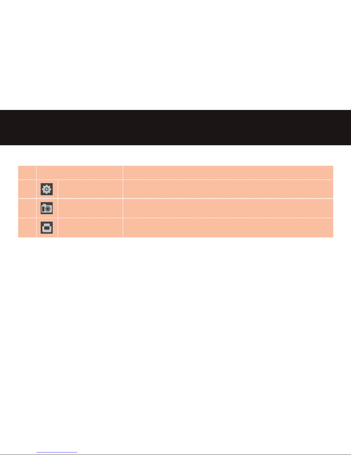
Name of Each Part Function
1
Setting
The operating environment of the Snooper is set.
2
Screenshot
It is used to capture images immediately and store them. (PNG, JPG)
3
Printer
Images are outputted by printer.
Page 30

30
4. Using the Snooper Viewer
Control of Snooper Viewer
Name of Each Part Function
Replay The le containing the selected images is replayed.
Pause The images being played are stopped for a while.
Stop The images being played are stopped and the play goes back to the beginning.
Previous File The le prior to that containing the images that are being played is replayed
1 Frame Backward The image goes 1 frame backward.
1 Frame Forward The image goes 1 frame forward.
Next File The image just after that being played is played.
Enlargement The image being played is enlarged.
Reduction The enlarged image is reduced.
1:1 Ratio The enlarged image is reduced in the original ratio.
Movement The enlarged image is moved to a dierent position that the user wants.
Image Rotation The image being played is rotated upward and downward.
Page 31
31
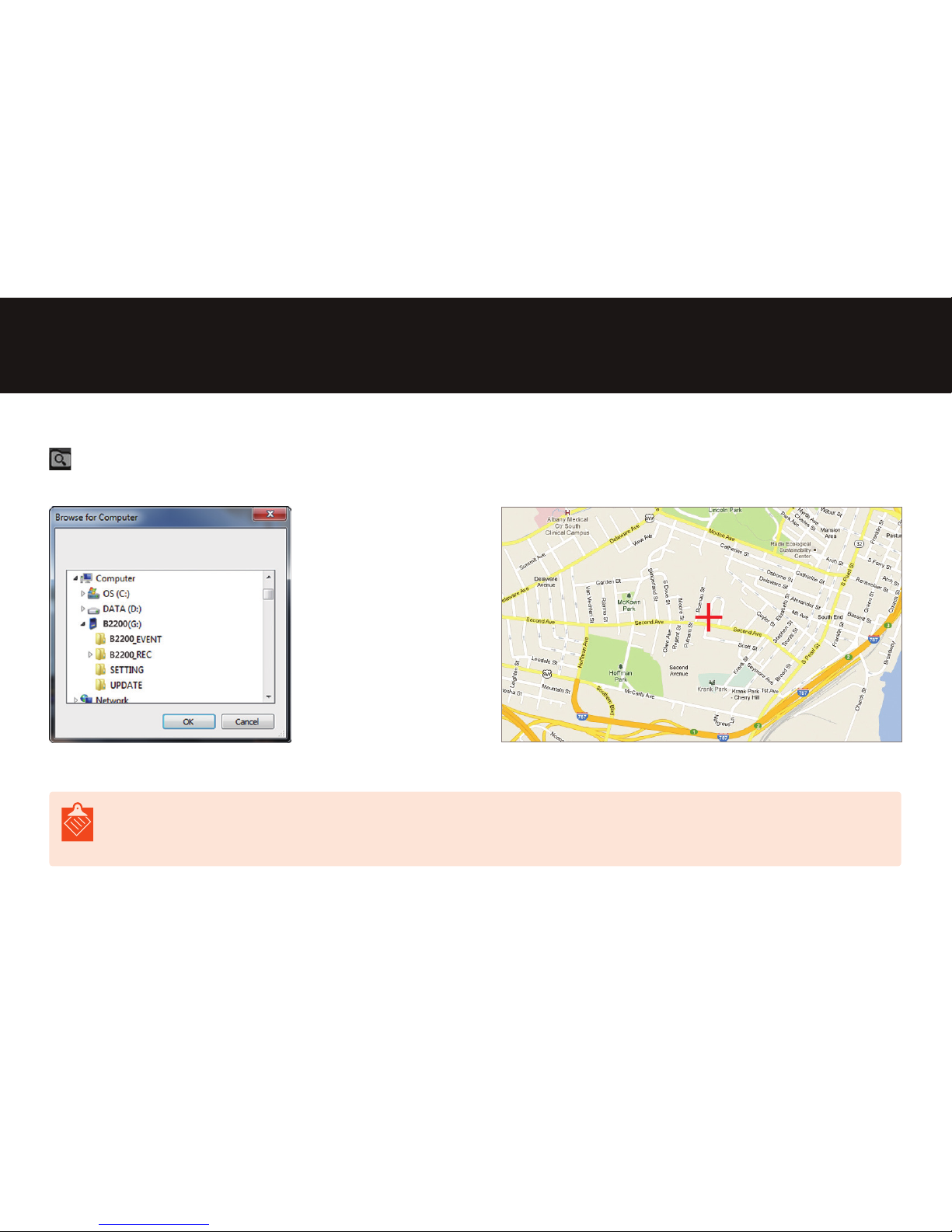
GPS Location Information
• This function is supported only for the products with an exterior GPS.
• This function works only when the Internet is connected.
4. Using the Snooper Viewer
Fetching Recorded Image Data Checking Driving Route (GPS)
Select the route through which the images you want have been
stored after pressing the button.
The GPS location information is shown on the map along with the
routing information.
Note
Page 32

32
4. Using the Snooper Viewer
Other Operation Functions
Full-size Image: If you right-click on the screen, the image is enlarged to the full size.
Page 33

33
4. Using the Snooper Viewer
Setting Program
Image/
Sound
Resolution The selection of maximum and minimum resolution of product is possible.
Image Quality
(Definition)
The video recording quality is set.
FPS (Frames Per
Second)
FPS stands for Frames Per Second: The frames that can be recorded in a
second. (Low: 15 fps, Medium: 24 fps, High: 30 fps)
Voice Recording Voice & Sound recording function “ON/OFF”
Speaker Volume The volume of buzzer sound and voice guidance sound is set.
Time
Time Setting
The recording time of the Snooper is set up. Time can be set just to the
time on the computer by retrieving the current time. (Check whether the
time on the computer is the standard time.)
DST (Daylight Saving
Time)
Under the DST system, clocks are adjusted forward one hour. In the
regions where the DST system is practiced, time can be set automatically
through this function. When the preset date arrives, the time of product is
moved ahead by 1 hour.
Standard Time Zone
The selection of standard time zone of each nation can be done through
the function.
Function
Shock Sensitivity The sensitivity of shock sensing sensor is set.
Number of Event
Files
The number of event files that can be stored is adjusted.
Parking Mode The parking mode is set through the function.
Motion Sensitivity The motion perception sensitivity during parking can be adjusted..
Battery Discharge
Blocking Voltage
The battery discharge blocking voltage during parking mode can be set.
Speed Unit The speed unit can be chosen.
Security LED The operating status of security LED during parking is set.
Viewer
Setting
Language The change of language shown on the viewer is possible.
Speed Unit The selection of speed unit shown on the viewer can be done.
Page 34

34
4. Using the Snooper Viewer
Clock
Used to set the unit’s clock.
Select Retrieve Time to use the computer’s system clock settings.
Page 35

35
4. Using the Snooper Viewer
GMT Setting (Time Zone)
The standard time zone corresponding to the region of each country is selected.
microSD Memory Card Storage Folder
Folder Name Note
REC
• The les of continuous driving recording and parking recording, including motion recording, are stored.
- Continuous driving recording: per 1 min.
- Motion parking recording: per 30 sec. / Continuous parking recording: per 1 min.
E.g.) Continuous driving recording: 20120412_111535_I.avi, Parking recording: 20120412_111535_P.avi
EVENT
• Shock recording and event recording during parking are stored.
- Event (Shock) recording: per 30 sec. (Basic capacity: 10-40 les stored)
- Event recording during parking: per 30 sec.
E.g.) Event during continuous driving recording: 20120412_111535_I.avi, Event during parking recording:
20120412_111535_P.avi
UPDATE
• The folder is used for the latest rmware update.
• In the folder is stored the “Text (*.txt)” le through which you can check the rmware version.
Page 36

36
4. Using the Snooper Viewer
Firmware Upgrade
1
Connect the microSD memory card to the computer.
2
Create the “UPDATE” folder in the microSD card.
3
Copy the rmware le into the "UPDATE" folder.
4
Connect the microSD card to the DVR-2HD and connect the power.
5
Once the power is connected, the rmware is upgraded, the body reboots and the upgrade process is completed.
• Do not forcibly turn o the power or remove the microSD card while the rmware is being upgraded. The system can
malfunction.
• The le system for the microSD card shall necessarily be the FAT16 or FAT32. Other le systems including the NTFS are not
supported.
Note
Page 37

37
5. Product Specications & Product Certication Process
Product Specications
• The rmware update of this product
is possible. Therefore, if the user
needs to update the rmware for
the quality improvement of product,
the update is possible. The update
les can be downloaded on our
company’s home page.
(www.snooperneo.co.uk)
• The specications of this product
can be modied without any
prior notication to the users
for the improvement of product
performance.
Classication DVR-2HD
Camera
Image Sensor 2-megapixel
Channel 1 channel
Angle of View 130°
Image Compression
Mode
H.264
Recording
Resolution 1280X720(HD)
Frame 30 fps max.
Recording Mode Continuous/Event/Parking Mode
Event Mode Perception of 3-axis shock sensor
Event Recording Mode
Applied for 15 sec. before and after
shock (30 sec. total)
Parking Mode Motion detection, 3-axis shock sensor
GPS
Velocity, Location,
Google Maps®
Supported
Storage
Basic Capacity microSD memory card 8GB or 16GB
Maximum Capacity 32GB
Audio
Input Built-in MIC
Output Speaker (Voice guidance)
Power
Main Power DC 12-24V, 200mA
Sub Power (Built-in) Supercapacitor
Others
Voice Guidance Supported
Security LED Supported
Note
Page 38

38
5. Product Specications & Product Certication Process
KCC
Certicate of Broadcasting and Communication Equipment
CE
Certicate of Safety and Quality for the European Market
FCC
Certicate of Federal Communications Commission of the USA
RoHS
Restriction of Hazardous Substances Directive
Product Certication Process
Page 39

39
6. Troubleshooting
If you are having trouble with this product, please check the following troubleshooting information before requesting servicing.
Contact Snooper Technical Support only if the problem persists after implementing the measures described below.
Problem Solution
Video recordings are not being saved to the microSD
card.
• Remove the microSD card and try inserting it again.
The Snooper is unable to read the memory card.
• Format the microSD card and try again.
• If the microSD card is old (expired), replace it with a new one.
What happens if the microSD card becomes full?
• Existing recording data are overwritten with new data, starting
with the oldest.
The recordings have poor picture quality.
• Check to see if the protective lm has been removed from the
camera lens.
• Check to see if the camera lens is dirty.
• Check to see if the windshield is dirty or has obstacles such as
dark tinting.
The DVR is not working.
• Check the power connection.
• Check to see if you are using an original power cable from the
manufacturer.
• For further assistance and troubleshooting, please call Snooper Technical on 01928 579579.
Note
Page 40

40
A wholly owned subsidiary
of Cobra Electronics UK Ltd
Like us at
snooperuk
Follow us @
snooperuk
www.snooper.co.uk
Performance Products Ltd, Cleaver House, Sarus Court, Manor Park, Runcorn WA7 1UL. Tel 0333 240 1000 Fax 0333 240 1100
 Loading...