

Page 1
Wireless Video Scope
Snap-on 1
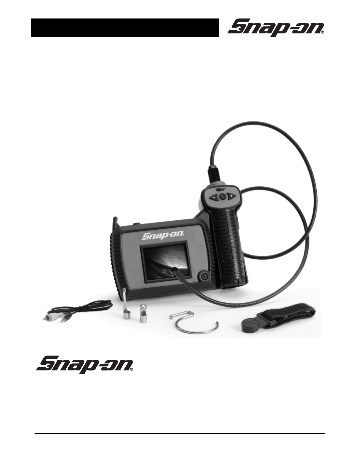
Wireless Video Scope
BK5500W
Page 2

Page 3

Wireless Video Scope
Snap-on 3
Table of Contents
General Safety Information ............................................................... 4
Work Area Safety ............................................................................ 4
Personal Safety ............................................................................... 4
Battery Precautions ......................................................................... 4
Wireless Video Scope Use and Care .............................................. 5
Specific Safety Information ............................................................... 6
FCC Compliance Statement ........................................................... 6
FCC Interference Statement ........................................................... 6
FCC Exposure Statement ............................................................... 7
PAL/SECAM Statement .................................................................. 7
Wireless Video Scope Safety .......................................................... 7
Description ...................................................................................... 8
Specifications .................................................................................. 8
Standard Equipment ........................................................................ 9
Assembly ......................................................................................... 9
To Install Batteries in either the Display Unit or the Imager Handle:9
To connect the Imager to the Imager Handle: .............................. 10
Installing an Accessory ................................................................. 10
To connect the mirror: ................................................................... 10
Tool and Work Area Setup .............................................................. 10
Operating Instructions ..................................................................... 11
Using the Display Unit and Imager ................................................ 11
To turn the Display Unit on: ........................................................... 11
To turn the Handle on: .................................................................. 11
To adjust the brightness of the LED light: ..................................... 11
Typical Applications ....................................................................... 12
Instructions for the Video-out feature ............................................ 12
Transportation and Storage ............................................................ 13
Maintenance Instructions ................................................................ 13
Additional Accessories .................................................................... 13
Snap-on Service Center Locations ................................................. 14
Troubleshooting ............................................................................... 15
Replacement Accessory Parts Numbers ....................................... 16
Warranty ............................................................................................ 16
Page 4
Wireless Video Scope
4 Snap-on
General Safety Information
Read and understand all
instructions. Failure to follow all
instructions listed below may result
in electric shock, fire and/or serious
personal injury.
SAVE THESE INSTRUCTIONS!
Work Area Safety
Keep your work area clean and well
lit. Cluttered benches and dark areas
may cause accidents.
Do not operate electrical
devices or the wireless video
scope in explosive atmospheres,
such as in the presence of
flammable liquids, gases, or heavy
dust. Electrical devices or the
wireless video scope can create
sparks which may ignite the dust or
fumes.
Do not use the wireless video
scope around corrosive chemicals.
Keep bystanders, children, and
visitors away while operating the
wireless video scope. Do not let
visitors contact the unit.
Personal Safety
Stay alert, watch what you are
doing and use common sense. Do
not use the wireless video scope
while tired or under the influence of
drugs, alcohol, or medications. A
moment of inattention while operating
tools may result in serious personal
injury.
Do not overreach. Keep proper
footing and balance at all times.
Proper footing and balance enables
better control of the tool in
unexpected situations.
Use safety equipment. Always
wear eye protection. Dust mask, nonskid safety shoes, hard hat, or
hearing protection must be used for
appropriate conditions.
Use proper accessories. Do not
place this product on any unstable
cart or surface. The product may fall
causing serious injury to a person or
serious damage to the product.
Prevent object and liquid
entry. Never spill liquid of any kind on
the video display unit. Liquid
increases the risk of electrical shock
and damage to the product.
Do not use this device for personal
or medical use/inspection in any
way.
The unit is not shock-resistant. Do
not use it as a hammer or drop it.
Battery Precautions
Remove the batteries when
cleaning the unit.
Remove the batteries before
storing the unit for a long time.
When necessary, REPLACE ALL
BATTERIES in this unit with new
ones.
Use only the size and type of
battery specified.
Be sure to install the battery with
the correct polarity as indicated in
the battery compartment.
Properly dispose of the battery.
Exposure to high temperatures can
Page 5

Wireless Video Scope
Snap-on 5
cause the battery to explode, so do
not dispose of in a fire. Place tape
over the terminals to prevent direct
contact with other objects. Some
countries have regulations concerning
battery disposal. Please follow all
applicable regulations.
Wireless Video Scope Use and
Care
Use the wireless video scope only
as directed. Do not operate the
inspection unit unless the owner’s
manual has been read and proper
training has been completed.
Do not immerse the handheld
display unit or imager handle in
water. Store in a dry place. Such
measures reduce the risk of electric
shock and damage. The imager head
and the cable are water resistant
when the unit is fully assembled, but
the video display unit is not.
Do not use the camera if
condensation forms inside the
lens. Let the water evaporate before
using again.
Do not use tool if ON/OFF switch is
not properly working. Any tool that
cannot be controlled with the switch is
dangerous and must be repaired.
Store idle equipment out of the
reach of children and other
untrained persons. Equipment is
dangerous in the hands of untrained
users.
Maintain the wireless video scope
with care. Properly maintained tools
are less likely to cause injury.
If unit is dropped check for
breakage of parts, and any other
conditions that may affect the
tool’s operation. If damaged, have
the tool serviced before using. Many
accidents are caused by poorly
maintained tools.
Use only accessories that are
recommended by the manufacturer
for your tool. Accessories that may
be suitable for one tool may become
hazardous when used on another
tool.
Dry your hands before turning the
unit ON or OFF and before
replacing batteries.
Protect against excessive heat. The
product should be situated away from
heat sources such as radiators, heat
registers, stoves or other products
(including amplifiers) that produce
heat. Do not use the unit near moving
machinery or areas where the
temperature will exceed 113°F.
Do not attempt to take any pieces
of this unit apart unless directed to
by this manual.
Follow instructions for changing
accessories. Accidents are caused
by poorly maintained equipment.
Provide proper cleaning. Do not use
acetone to clean the unit. Instead, use
isopropanol.
Gently clean the LCD with a dry
cloth. Remove batteries before
cleaning.
Stop using the unit if it starts
smoking or emitting noxious
fumes.
Remove the batteries and refer
servicing to qualified service
personnel under any of the
following conditions:
If liquid has been spilled or
objects have fallen into product;
If product does not operate
normally by following the
operating instructions;
Page 6
Wireless Video Scope
6 Snap-on
If the product has been dropped
or damaged in any way;
When the product exhibits a
distinct change in performance.
If you have any questions regarding the
service or repair of this machine, call or
write the appropriate repair center
location (see "Snap-on Service Center
Locations" on page 14).
Technical questions can be directed to our
toll free number at 1-877-762-7664
Monday through Friday 6:30 am to 5:00 pm
Central Time (U.S. customers only).
Specific Safety Information
Read this operator’s manual
carefully before using. Failure to
understand and follow the contents
of this manual may result in
electrical shock, fire and/or severe
personal injury.
FCC Compliance Statement
This device complies with Part 15 of the
FCC Rules. Operation is subject to the
following two conditions:
1. This device may not cause harmful
interference.
2. This device must accept any
interference received, including
interference that may cause
undesired operation.
WARNING! Changes or
modifications not expressly
approved by the party responsible
for compliance could void the user’s
authority to operate the equipment.
FCC Interference Statement
This equipment has been tested and found
to comply with the limits for Class B digital
devices, pursuant to Part 15 of the FCC
rules. These limits are designed to provide
reasonable protection against harmful
interference in a residential installation.
This equipment generates, uses, and can
radiate radio frequency energy and, if not
installed and used in accordance with the
instructions, may cause harmful
interference to radio communications.
However, there is no guarantee that
interference will not occur in a particular
installation. If this equipment does cause
harmful interference to radio or television
reception, which can be determined by
turning the equipment off and on, the user
is encouraged to try to correct the
interference by one or more of the
following measures:
Reorient or relocate the receiving
antenna.
Increase the separation between the
equipment and receiver.
Connect the equipment into an outlet
on a circuit different from that to which
the receiver is connected.
Consult the dealer or an experienced
radio/TV technician for help.
Use of shielded cable is required to comply
with Class B limits in Subpart B of Part 15
of the FCC rules.
Do not make any changes or modifications
to the equipment unless otherwise
specified in the manual. If such changes or
modifications should be made, you could
be required to stop operation of the
equipment.
Page 7

Wireless Video Scope
Snap-on 7
FCC Exposure Statement
This portable transmitter with its antenna
complies with FCC/IC RF exposure limits
for general population/uncontrolled
exposure.
PAL/SECAM Statement
The video output port found on this device
puts out a standard NTSC video signal, but
does not output PAL or SECAM video
signals, or video signals in any other
format. If the video output of this device is
connected directly to the input jack of a
PAL or SECAM television or other PAL or
SECAM audio-visual equipment, no image
will be visible to the user.
Wireless Video Scope Safety
Do not place tool into anything
or anywhere that may contain a live
electrical charge.
FOR WALLS: For inspecting inside
walls, be sure to shut off the circuit
breaker to the whole house before
using the tool behind any of the walls.
FOR PIPES: If you suspect a metal
pipe could contain an electrical
charge, have a qualified electrician
check the pipe before using the tool.
Ground circuits, in some cases, can
be returned to cast iron pipes and
cause them to be charged.
FOR AUTOMOBILES/HEAVY
EQUIPMENT/MOTORSPORTS: Be
sure the automobile, heavy
equipment or motorsport is not
running during inspection. Metal and
liquid under the hood may be hot.
Always clean imager with mild
detergent or solvent after exposure to
any chemical, especially petroleum-
based products. Exposure to
petroleum-based substances will
eventually degrade the imager head
covering.
GENERAL USE: Do not use
anywhere the unit may come into
exposure with hazardous chemicals,
electrical charges or moving parts.
Such situations may result in serious
injury or death.
SAVE THESE INSTRUCTIONS!
Page 8

Wireless Video Scope
8 Snap-on
Description
The BK5550W wireless video scope displays live color video from an imaging sensor and
lighting source connected to a flexible imager cable. It can be used to look into tight spots
and beam back real-time video to a color LCD. Accessories (mirror and magnet) are
included to attach to the imager head to provide application flexibility.
Specifications
Recommended Use Indoor
Optimal Viewing Distance 1/2 in to 12 in (1.3 cm to 30.5 cm)
Power Supply 6 AA Alkaline cells
Estimated Battery Life 4.5 hours of continuous use
Weight 4.3 lbs (1.95 kg)
Dimensions
Display Unit:
Power Supply 3 AA Alkaline cells
Length 1.6 in (4.1 cm)
Width 5.4 in (13.7 cm)
Height 3.7 in (9.4 cm)
Resolution 320 x 240
Screen 2.7 in (6.9 cm) LCD
Imager Handle:
Power Supply 3 AA Alkaline cells
Length 2.25 in (5.7 cm)
Width 2.12 in (5.4 cm)
Height 5.4 in (13.7 cm)
Imager:
Length 36 in (0.9 m)
Optional Accessories lengths 72 in (1.8 m) and 120 in (3.05 m)
Wireless Reception Range 100 ft (30.4 m) (unobstructed line-of-sight distance)
Video-out port 3.5 mm TRS (Tip Ring Sleeve)
Video Signal NTSC
Operating Environment:
Temperature 32 °F to 113 °F (0 °C to 45 °C)
Humidity 5 % to 95 % non-condensing (display unit)
Storage Temperature -4 °F to 158 °F (-20 °C to 70 °C)
Water Resistance Imager head and extensions up to 10 ft (3.05 m) water
depth. (When assembled)
Page 9

Wireless Video Scope
Snap-on 9
Standard Equipment
The wireless video scope comes with
the following items, as shown:
1. Display Unit
2. Imager
3. Handle
4. Accessories
hanger hook
magnet strap
video-out cable
protective carrying case
5. Imager Accessories
mirror
magnet
System Components
Assembly
NOTICE: Be sure to read Battery
Precautions (on page 4).
To Install Batteries in either the
Display Unit or the Imager Handle:
1. Open battery compartment cover by
depressing tab and pulling door open.
Insert three (3) new AA batteries into
the proper slots. Proper battery
orientation is indicated on the battery
compartment.
2. Snap battery compartment cover back
into place.
Installing Batteries
Page 10

Wireless Video Scope
10 Snap-on
To connect the Imager to the
Imager Handle:
1. Make sure the keyed ends are
properly aligned.
2. Press imager connector firmly into the
unit until the retaining ring is
completely engaged.
If the keyed ends are not properly
aligned, the connector will not be fully
seated. Match up the arrows when
inserting the imager. In this case,
rotate the imager connector until the
tabs are fully seated. The imager
connector should only need to rotate a
maximum of 180 degrees.
Connecting the Imager to the Imager Handle
Installing an Accessory
The two included accessories, (mirror and
magnet) attach to the imager the same
way.
To connect the mirror:
Match up the Slot in the Mirror with
the Alignment Pin on the Imager and
push together to lock in place.
Installing Accessory-Mirror
Installing Accessory-Slot and Alignment Pin
Tool and Work Area Setup
To prevent serious injury, proper setup of the tool and work area is required. The
following procedures should be followed:
1. Review the General Safety Information (on page 4) of this manual.
2. Check work area for: adequate lighting, flammable liquids, vapors or dust that may
ignite.
3. Follow tool set-up according to specific tool operator's manual.
Page 11

Wireless Video Scope
Snap-on 11
Operating Instructions
Do not use excessive force to insert or bend the imager.
Do not use the wireless video scope to modify surroundings, clear pathways or
clogged areas, or as anything other than an inspection device.
The imager connector, handle and display unit are not water resistant. The imager
head and its covering are water resistant, but are not acid-proof or fire proof.
Petroleum-based products will ruin the imager's protective plastic covering over time.
Avoid submersing the imager head into corrosive, oily places.
Using the Display Unit and Imager
To turn the Display Unit on:
1. Hold the viewer with the LCD screen
facing you.
2. Depress power button to turn on.
Turning the Display Unit on
To turn the Handle on:
1. Verify that the channel switch located
on the display unit and imager cable
are on the same frequency number.
2. Push the ON/OFF switch away from
you to turn on the imager handle.
Turning the Handle on
To adjust the brightness of the LED
light:
Press the arrow key with the (+) sign
to increase the brightness and press
the arrow key with the (-) sign to
decrease the brightness.
Using the Imager LED's
Page 12

Wireless Video Scope
12 Snap-on
Typical Applications
The Snap-on Wireless Video Scope is
designed as a remote inspection device.
Typical applications might include
automotive inspection, cable routing, heavy
equipment / boat / aircraft inspection, etc.
Automotive Inspection
Cable Routing
Instructions for the Video-out
feature
To use the auxiliary video-out port on the
BK5500W:
1. Remove the rubber protective cap
from the video-out port on the top of
the unit.
2. Find the auxiliary video cable that is
provided in the case with the
BK5500W.
3. Plug the male end of the 3.5 mm mini-
plug into the video-out port.
4. Plug the RCA end of the video cable
into the video input on the video
monitor. This port is typically colored
yellow.
5. Verify the video monitor is set to
display the video from the designated
video port.
Please review the PAL/SECAM Statement
(on page 7).
Video-out port
Page 13

Wireless Video Scope
Snap-on 13
Transportation and Storage
1. Avoid exposing the unit to continuous vibration or extreme hot and cold temperatures.
2. Always store the wireless video scope indoors in the case it came with.
3. Always remove the batteries if the unit will not be used for an extended period of time.
Maintenance Instructions
Make sure the batteries have been removed from the unit before
performing maintenance.
The Snap-on wireless video scope has been designed to require little maintenance.
However, in order to maintain its performance, you must always follow these guidelines:
1. Always handle the device with care. It is not shock-resistant and should not be
banged or dropped. Treat it as you would any other sensitive optical device.
2. Always clean the imager head after use with mild detergent.
3. Use only isopropanol swabs to clean the connections.
4. Avoid rubbing too hard on the LCD. After use, wipe the display clean gently with a dry
cloth.
5. Do not disassemble this device beyond what is shown in the manual. Doing so will
void your warranty.
Additional Accessories
Magnet and Mirror attachments – BK5500-2
8.5 mm diameter Imager, 72 in long – BK5500-7
8.5 mm diameter Imager, 120 in long – BK5500-9
Ultra Violet Imager, 36 in long – BK5500-10
Dual View Imager, 36 in long – BK5500-12
5.5 mm diameter Imager, 36 in long – BK5500-13
Digital Video Capture Device (DVR) – BK5500-14
Page 14

Wireless Video Scope
14 Snap-on
Snap-on Service Center Locations
If you have any questions regarding the service or repair of this
machine, please call or write the most geographically convenient service center listed
below:
Eastern Repair Center (USA)
6320 Flank Dr.
Harrisburg, PA 17112
USA
Toll Free # -USA only:
(800) 848-5067
Telephone: (717) 652-7914
Fax: (717) 652-7123
Snap-on Tools (Australia) Pty Ltd.
National Distribution Centre
Unit 6/110 Station Road
PO Box 663
Sven Hills, NSW 1730 Australia
Telephone: (61) 2-9837-9100
Fax: (61) 2-9624-2578
e-mail: sota.webmasters@snapon.com
Northern Repair Center (USA)
3011 E. RT 176, Dock 8
Crystal Lake, IL 60014
USA
Toll Free # – USA only:
(877) 777-4412
Telephone: (815) 479-6850
Fax: (815) 479-6857
Snap-on Tools Singapore PTE, Ltd.
25 Tagore Lane #01-01
Singapore 787602
Telephone: +(65) 6451-5570
Fax: +(65) 6451-5574
e-mail: esale.sg@snapon.com
Internet: http://snapon.com.sg
Western Repair Center (USA)
3602 Challenger Way
Carson City, NV 89706-0753
USA
Toll Free # – USA only:
(888) 762-7972
Telephone: (775) 883-8585
Fax: (775) 883-8590
Snap-on Tools Japan, K.K.
Snap-on, Bahco, and Cartec
Also serving Taiwan and Micronesia
(Distribution Center and Technical Repair
Center)
2-1-6 Shinkiba, Koto-ku,
Tokyo, 136-0082 JAPAN
Telephone: +81 3 5534 1280
Fax: 81-5534-1284
e-mail: SOJ-INFO@snapon.co.jp
OEM, National Accounts, GSA
Distribution: +81-3-5534-1300
Industrial: +81-3-5534-1281
BAHCD: +81-3-5534-1301
Technical Repair Center: +81-3-5534-1289
UK Repair Centre
Snap-on Tools, Ltd.
Telford Way,
Kettering
Northants NN16 8UN, England
Telephone: 01536 413855
Fax: 01536 410740
Snap-on Tools of Canada Repair Center
7403 48th St. S.E.
Calgary, Alberta T2C 4H6
Toll Free #: (866) 824-0525
Telephone: (403) 720-4525
Fax: (403) 720-4524
e-mail: canadianquestions@snapon.com
Page 15

Wireless Video Scope
Snap-on 15
Troubleshooting
Symptom Possible Reason Solution
Display turns ON but
does not show
image.
Loose or dirty imager cable
connections.
- Check Cable Connections,
clean if required
- Re-attach
Imager head covered by
debris.
Make sure imager head is
not covered with debris.
Channel selection switches
on handle and viewer not
tuned to same channel.
Check channel switch
settings on handle and
viewer – must set to same
channel number
Handle batteries have run
out.
Check battery status light on
power button of handle. If
batteries are low or handle
does not turn on, replace
batteries.
Image contains
excessive static or
"snow," or the image
appears and
disappears
erratically.
Battery power is low, causing
transmitted signal to become
weak.
Check battery status on
imager handle and viewer
unit.
Too many obstacles or too
much distance between
viewer unit and imager
handle.
Move handle and viewer
unit closer to each other
(less than 100 feet (30m)
line-of sight), or remove
obstacles that exist between
the handle and the viewer.
Loose or dirty imager cable
connections.
- Check Cable Connections,
clean if required
- Re-attach
LEDs on imager
head are dim at max
brightness
Battery power is low. Check battery status, and
replace batteries if
necessary.
Display switches
between black and
white
Battery power is low Check battery status, and
replace batteries if
necessary.
Handle and/or
viewer unit will not
turn on.
Battery power is very low. Replace batteries.
Page 16

Wireless Video Scope
16 Snap-on
Replacement Accessory Parts Numbers
Imager Head – BK5500-1; Magnet and Mirror - BK5500-2; Protective Carrying Case BK5500W-1
Warranty
Limited Two (2) Year Warranty
Snap-on Tools Company (the "Seller") warrants only to the original purchaser that under
normal use, care and service, the Equipment (except as otherwise provided herein) shall
be free from defects in material and workmanship for twoyears from the date of original
invoice. SELLER'S OBLIGATIONS UNDER THIS WARRANTY ARE LIMITED SOLELY
TO THE REPAIR OR, AT SELLER'S OPTION,REPLACEMENT OF EQUIPMENT OR
PARTS WHICH TO SELLER'S SATISFACTION ARE DETERMINED TO BE DEFECTIVE
AND WHICH ARE NECESSARY IN SELLER'S JUDGMENT, TO RETURN THIS
EQUIPMENT TO GOOD OPERATING CONDITION. NO OTHER WARRANTIES,
EXPRESS OR IMPLIED OR STATUTORY, INCLUDING WITHOUT LIMITATION ANY
IMPLIED WARRANTY OR MERCHANT ABILITY OR FITNESS FOR A PARTICULAR
PURPOSE, SHALL APPLY AND ALL SUCH WARRANTIES ARE HEREBY EXPRESSLY
DISCLAIMED. This warranty does not cover (and separate charges for parts, labor and
related expenses shall apply to) any damage to, malfunctioning,in operability or improper
operation of the Equipment caused by, resulting from or attributable to (A) abuse, misuse
or tampering;(B) alteration, modification or adjustment of the Equipment by other than
Seller's authorized representatives; (C) installation, repair or maintenance (other than
specified operator maintenance) of the Equipment or related equipment, attachments,
peripherals or optional features by other than Seller's authorized representatives; (D)
improper or negligent use,application, operation, care, cleaning, storage or handling; (E)
fire, water, wind, lightening or other natural causes; (F) adverse environmental conditions,
including, without limitation, excessive heat, moisture, corrosive elements, or dust or other
air contaminants, radio frequency interference, electric power failure, power line voltages
beyond those specified for the Equipment, unusual physical, electrical or electromagnetic
stress and/or other condition outside of Seller's environmental specifications;(G) use of
Equipment in combination or connection with other equipment, attachments, supplies or
consumables not manufactured or supplied by Seller; or (H) failure to comply with any
applicable federal, state or local regulation,requirement or specification governing
emission analyzers and related supplies or consumables. Repairs or replacements
qualifying under this Warranty will be performed on regular business days during Seller's
normal working hours within a reasonable time following purchaser's request. All requests
for Warranty service must be made during the stated warranty period. This Warranty is
non-transferable.
Snap-on is a trademark of Snap-on Incorporated. © Snap-on Incorporated 2010.
Printed in USA.
Snap-on, 2801 80th St. Kenosha, WI 53143 www.snapon.com
Page 17

Drahtloses Video-Endoskop
Snap-on 17
Drahtloses Video-Endoskop
BK5500W
Page 18

FCC NOTIFICATION:
This device complies with Part 15 of the FCC Rules. Operation is
subject to the following two conditions:
(1) this device may not cause harmful interference, and
(2) this device must accept any interference received, including
interference that may cause undesired operation.
 Loading...