

Page 1
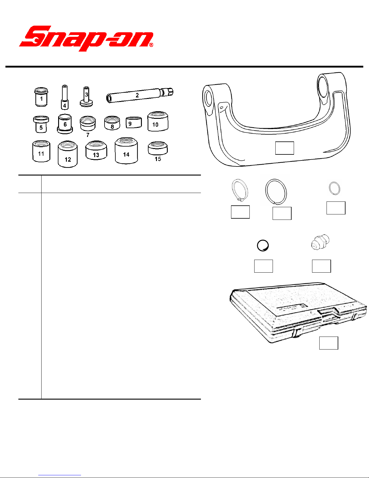
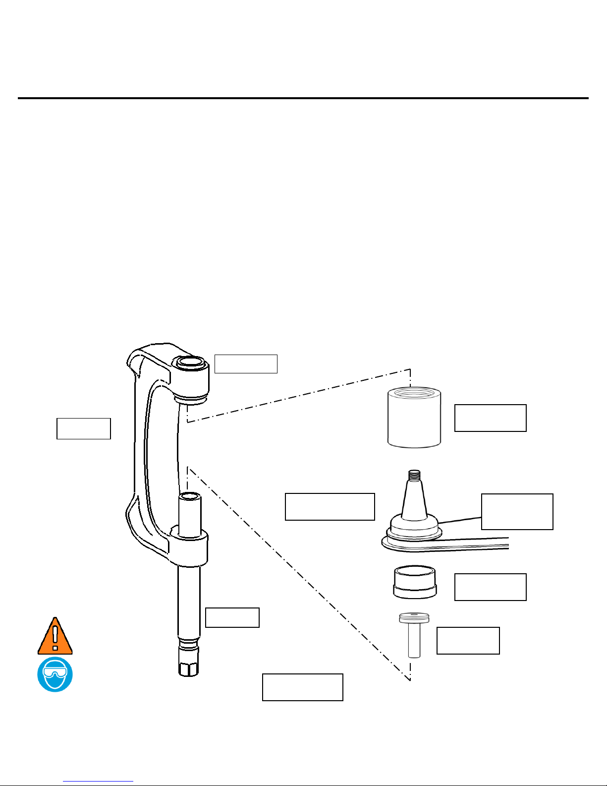
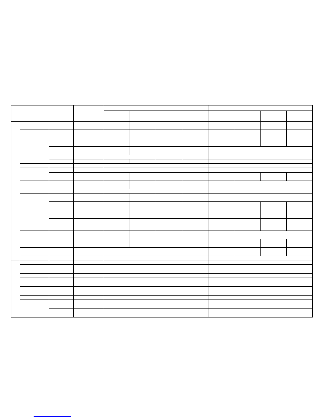
1
Item
No.
Part
No.
Description
1
BJP1-1A
SLEEVE ADAPTER
2
BJP1-2
PRESSURE SCREW
3
BJP1-3A
LARGE FACED (BALL JOINT)
PRESSURE PAD
4
BJP1-4A
SMALL FACED (UNIVERSAL
JOINT) PRESSURE PAD
5
BJP1-5A
ADAPTER
6
BJP1-6A
ADAPTER/EXTENSION
7
BJP1-7A
ADAPTER
8
BJP1-8A
ADAPTER
9
BJP1-9A
ADAPTER: ANGLE
10
BJP1-10A
ADAPTER: ANGLE
11
BJP1-11A
ADAPTER
12
BJP1-12A
ADAPTER
13
BJP1-13B
ADAPTER
14
BJP1-14A
ADAPTER
15
BJP1-16A
ADAPTER
16
BJP1F
PRESS FRAME
17
BJP1-17
GREASE FITTING
18
ME9A34
STEEL BALL
19
ME7A207
RETAINING RING
20
ME7A208A
LARGE SNAP RING
(11 RINGS REQ’D.)
21
ME7A209A
SMALL SNAP RING
22
PAKPB061
CARRYING/STORAGE CASE
19
BJP1-BALL JOINT
PRESS MASTER SET
20
21
18
17
22
16
BJP1-BALL JOINT PRESS MASTER SET
(Some component assembly required. See component assembly sections.)
Visit the Snap-on web site, www.snapon.com, for vehicle application
information and complete listing of available adapters.
ZBJP1B rev B 06/11/2014
Page 2
2
SAFETY INFORMATION
IMPORTANT SAFETY INSTRUCTIONS
This manual contains important safety and operating instructions for
the Snap-on® Ball Joint Press Master set. Refer to the information in
this manual as required for safe operation.
READ ALL INSTRUCTIONS
Read all the instructions in this manual. Read, understand and follow
all safety messages and instructions in this manual, and on all ball
joint press part components. Safety messages in this section contain
a signal word, a three-part message, and in some cases, an icon.
Safety symbols, when present, give a graphical description of the
potential hazard or how to avoid potential hazard.
WARNING
Wear safety goggles, user and bystander.
Be sure all adapter-to-adapter connections are secure.
Avoid misalignment of ball joint press assembly when
tightening pressure screw on ball joint and control arm.
If misalignment occurs, STOP tightening screw.
Unthread screw until assembly is loose. Properly realign
press assembly on ball joint and control arm.
WARNING
Refer to manufacture’s service manual for properly supporting and
raising of vehicles in a safe and secure manner.
ZBJP1B rev B 06/11/2014
Page 3
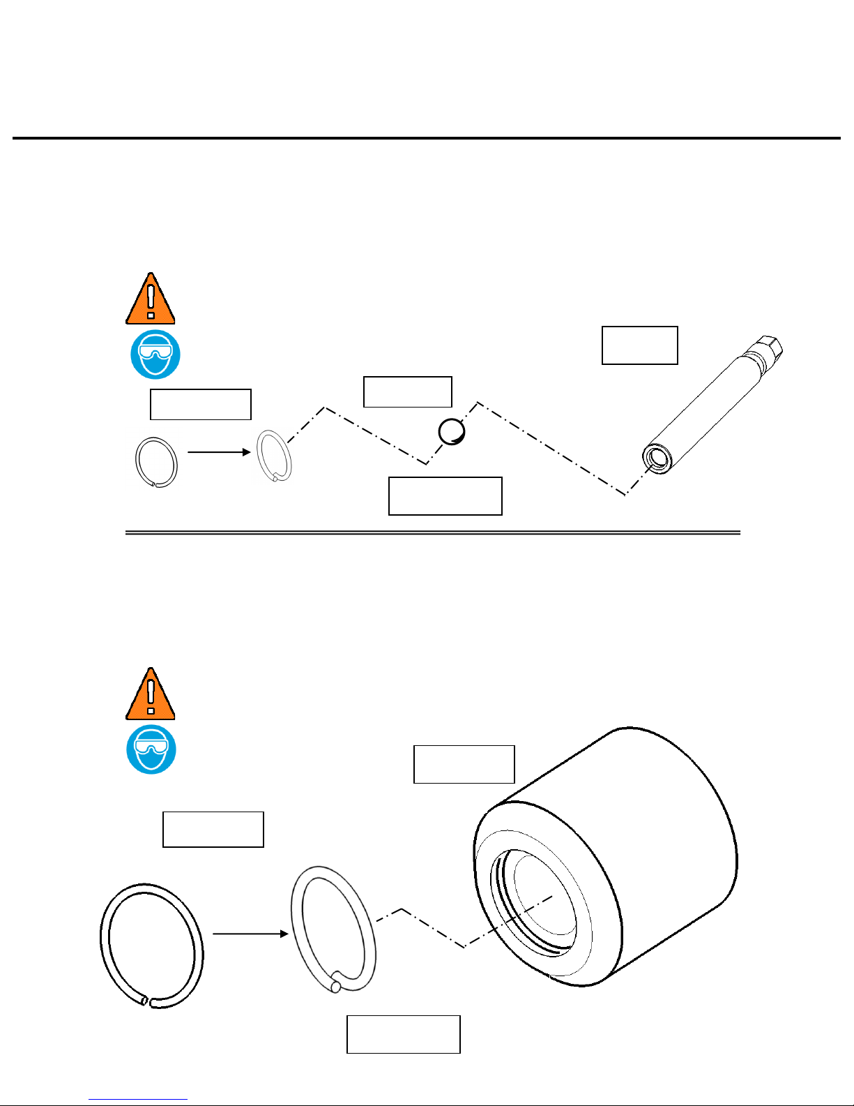
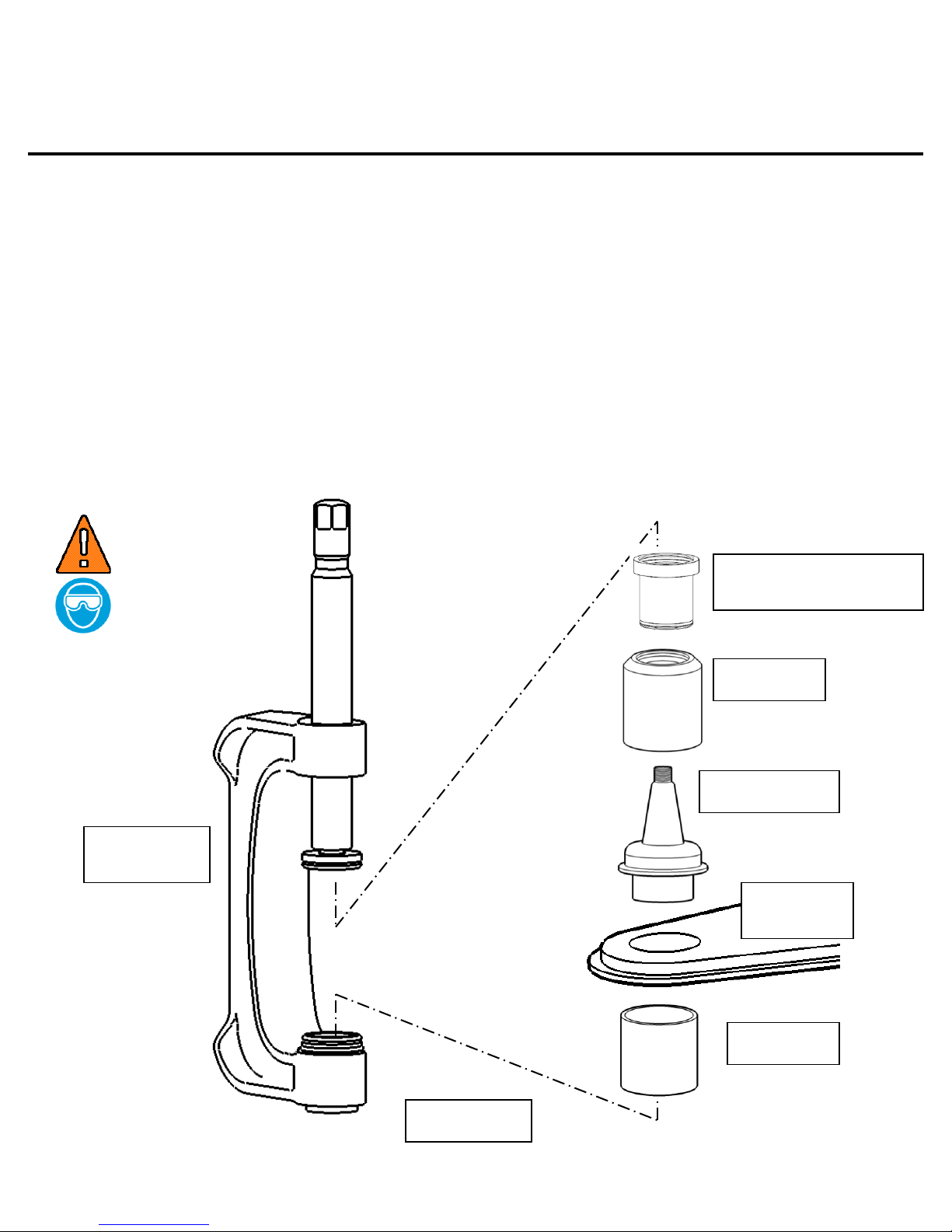
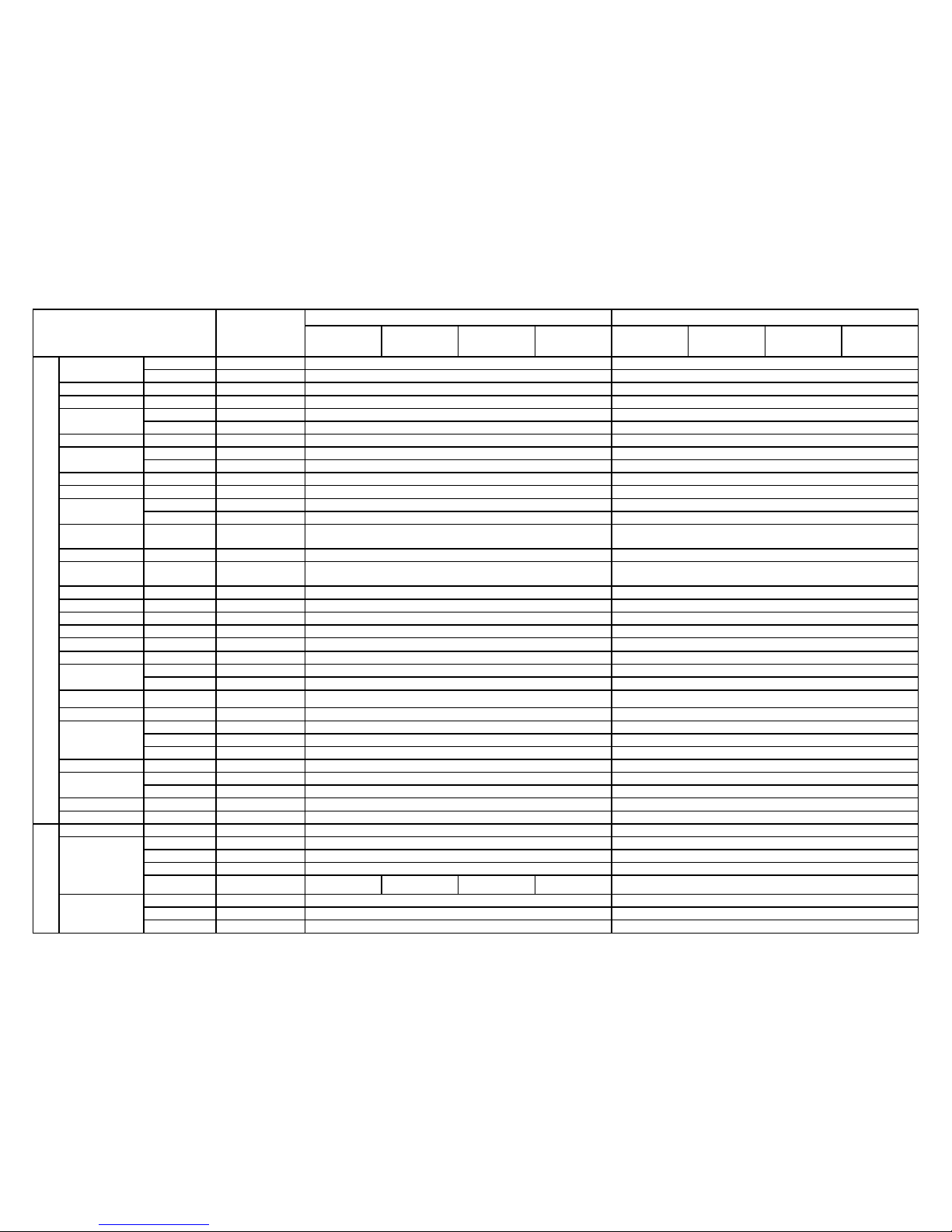
3
FIGURE - 1
FIGURE - 2
ME7A209A
ME9A34
BJP1-2
ME7A208A
BJP1-14A
Ball Joint Press Component Assembly
Insert steel ball (ME9A34) into opening of pressure screw (BJP1-2) as shown in FIG.
Secure steel ball inside screw by inserting small snap ring (ME7A209A) into internal
snap ring groove of screw as follows:
1. Place snap ring partially into groove while compressing ring so that the ends
overlap as shown in FIG. 1.
2. Press ring into screw opening until ring snaps securely into groove.
WARNING
Insert large snap ring (ME7A208A) into internal snap ring groove of each of the (11)
adapters in the parts list on page one (adapters BJP1-5A through BJP1-16A) as
follows:
1. Place snap ring partially into groove while compressing ring so that the ends
overlap as shown in FIG. 2.
2. Press ring into adapter opening until the ring snaps securely into groove.
WARNING
ZBJP1B rev B 06/11/2014
Page 4
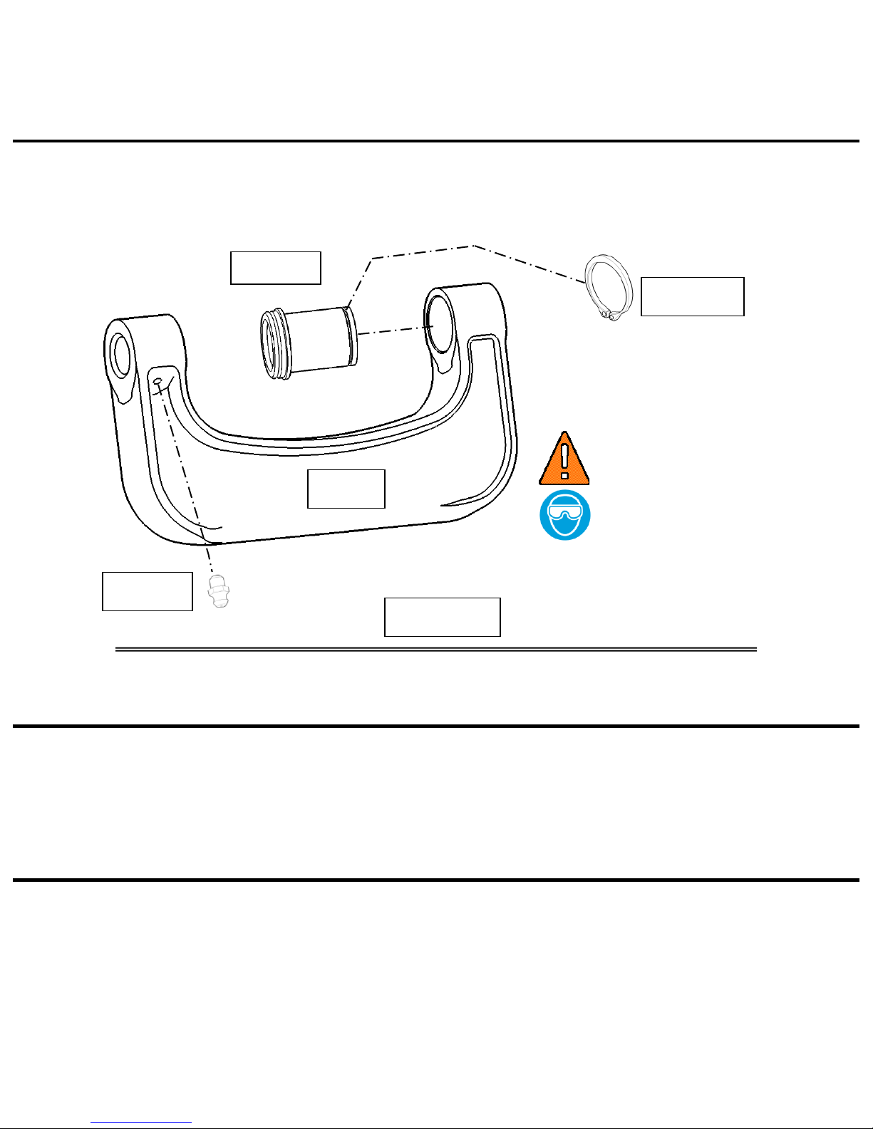
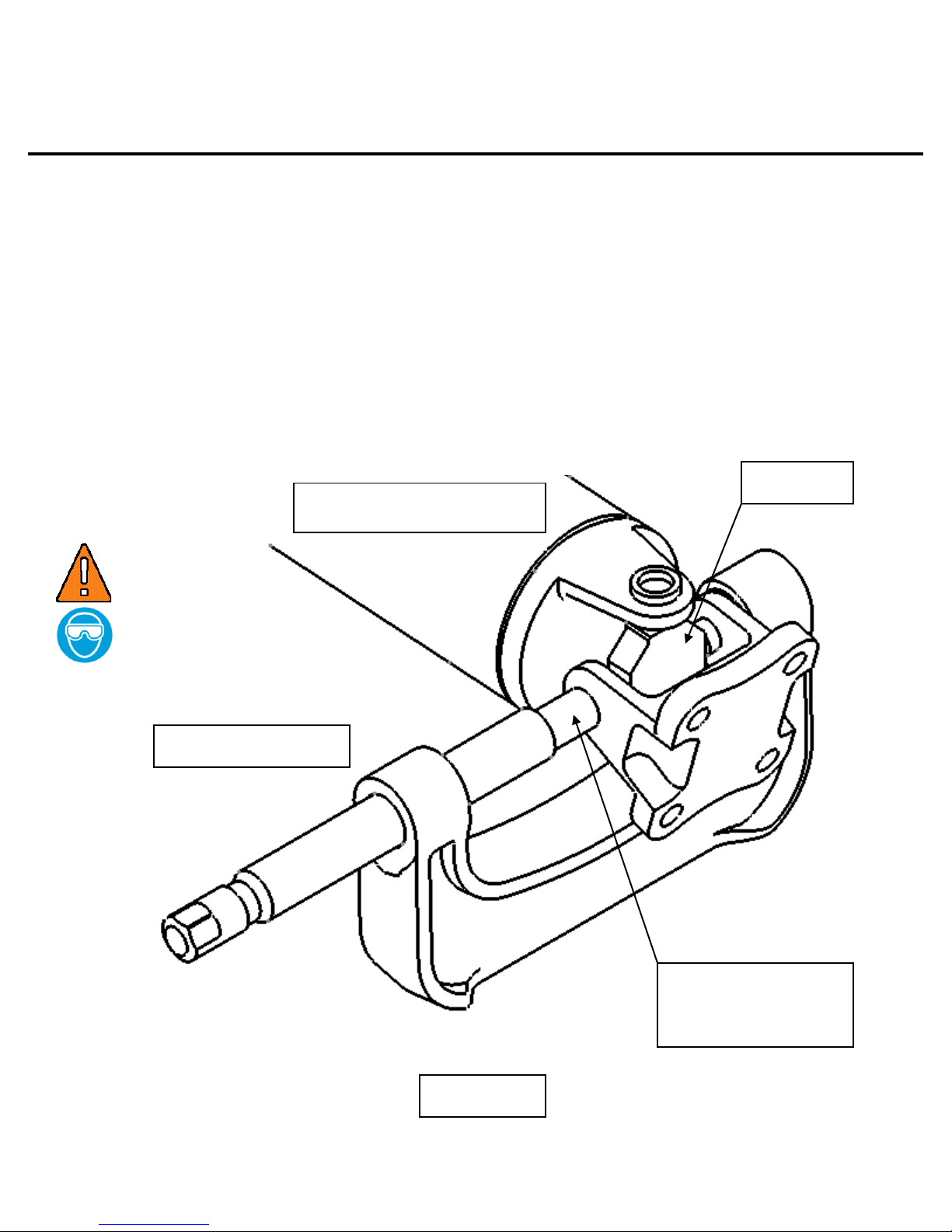
4
BJP1F
ME7A207
BJP1-1A
BJP1-17
FIGURE - 3
Ball Joint Press Component Assembly
Slide sleeve adapter (BJP1-1A) into hole of press frame (BJP1F) and secure with
retaining ring (ME7A207) as shown in FIG. 3. Use snap ring pliers with proper tip
size. Thread grease fitting (BJP1-17) into tapped hole of press frame as shown using
5/16” socket.
WARNING
Maintenance
The pressure screw threads need to be wiped clean and re-lubricated with chassis
grease on a regular basis. Use grease fitting (installed on screw side arm of frame)
to apply grease to the screw threads.
BJP1 - Operating Information
The BJP1 ball joint master set is designed to be used without removing the control
arm from the vehicle on most cars and trucks that have press-fit type ball joints.
NOTE: Some vehicles have the upper ball joint spot-welded to the control
arm. The weld must be cut before attempting to remove the ball joint.
ZBJP1B rev B 06/11/2014
Page 5
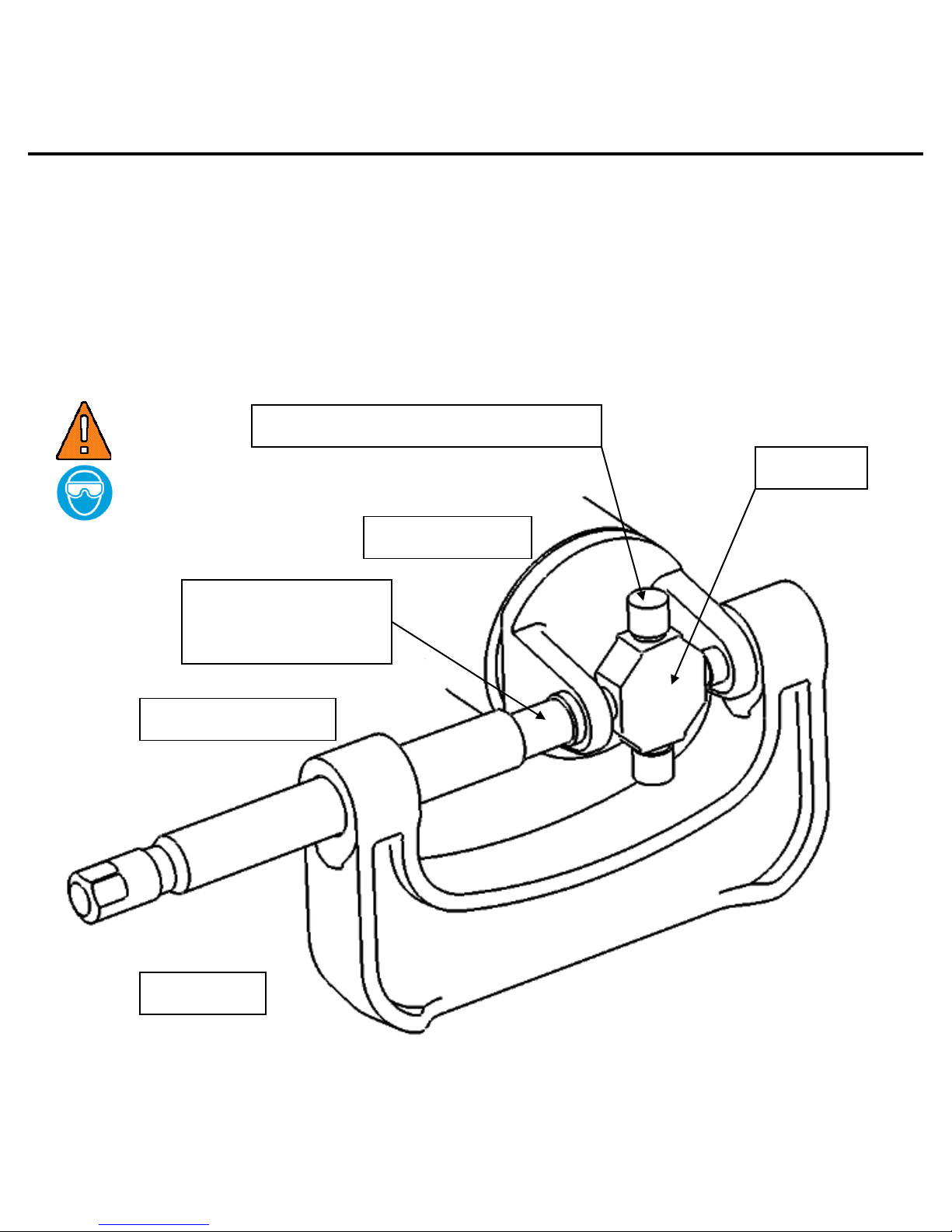
5
CONTROL
ARM
BJP1F
BJP1-2
ADAPTER
ADAPTER
BJP1-3A
BALL JOINT
FIGURE - 4
BJP1-1A
WARNING
Operating Instructions
Ball Joint Removal
(Refer to the safety information section for required safety instructions.)
1. Refer to the proper automotive service manual used for repair procedures on the specific vehicle
being serviced. Follow indicated procedures for removing all suspension components to obtain
clear access to the vehicle’s ball joint and control arm.
2. Refer to application chart to select the proper adapters for removing most types of ball joints on
most vehicle makes and models.
3. Thread pressure screw (BJP1-2) into end of frame. Insert ball joint pressure pad (BJP1-3A) into
pressure screw. (Force pressure pad completely down into pressure screw.)
4. Snap the selected adapters onto adapter sleeve (BJP1-1A) and ball joint pressure pad as shown in
FIG. 4.
5. Position press assembly over ball joint and control arm, as shown in FIG. 4.
6. Tighten pressure screw until removal adapters are snug against ball joint and control arm. Check
that the entire assembly is properly aligned. If not, STOP tightening screw, then loosen assembly
and re-align.
7. Apply torque to pressure screw until ball joint has been pressed out of control arm and into
receiving adapter.
ZBJP1B rev B 06/11/2014
Page 6
6
ADAPTER
PRESS
ASSEMBLY
BALL JOINT
ADAPTER
CONTROL
ARM
FIGURE - 5
BJP1-6A Extension
(Some Applications)
WARNING
Operating Instructions
Ball Joint Installation
(Refer to the safety information section for required safety instructions.)
1. Clean knuckle and control arm. Coat bore of control arm with a suitable lubricant.
2. Insert replacement ball joint into control arm bore as straight as possible and align properly in
bore.
3. Refer to application chart to select the proper adapters for replacing most types of ball joints on
most vehicle makes and models.
4. Snap selected adapters into place in the same manner as in the ball joint removal procedure. Use
adapter BJP1-6A between pressure pad (BJP1-3A) and adapter if additional length is needed, as
shown in FIG. 5.
5. Position press assembly over ball joint and control arm, as shown in FIG. 5.
6. Tighten pressure screw until installation adapters are snug against ball joint and control arm.
Check that the entire assembly is properly aligned. If not, STOP tightening screw, then loosen
assembly and re-align.
7. Apply torque to pressure screw until the ball joint flange is securely seated against face of control
arm bore.
ZBJP1B rev B 06/11/2014
Page 7
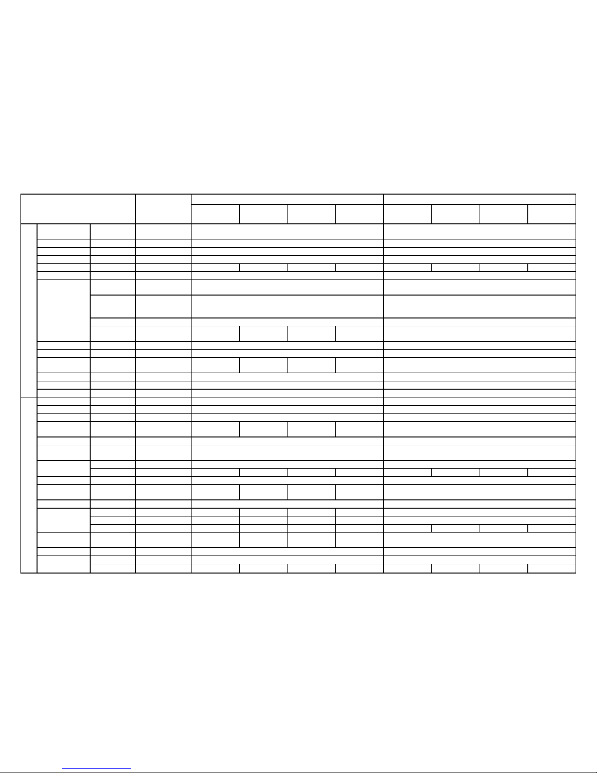
7
FIGURE - 6
DRIVE SHAFT ASSEMBLY
PRESS ASSEMBLY
U - JOINT
BJP1-4A
U-JOINT PRESSURE
PAD
UJP1 - Operating Instructions
The UJP1 universal joint set is designed to replace U-joints, either on or off the vehicle, on most cars and
trucks.
Universal Joint Removal
(Refer to the safety information section for required safety instructions.)
1. If necessary, remove ball joint pressure pad from pressure screw. Then insert universal joint
pressure pad (BJP1-4A) into pressure screw. (Force pressure pad completely down into pressure
screw.)
2. Securely support the drive shaft yoke assembly. Remove all external and/or internal locking rings.
3. If necessary, select one or a combination of adapters (BJP1-1A, BJP1-7A, BJP1-8A) to assist in U-
joint replacement.
4. Position press assembly around drive shaft yoke and align pressure pad with face of needle bearing
caps, as shown in FIG. 6 and FIG. 7.
5. Tighten pressure screw until one side of U-joint has been pressed completely out of yoke assembly.
6. Reposition press assembly, in the same manner as step-4, and tighten screw to remove the
remaining U-joint.
WARNING
ZBJP1B rev B 06/11/2014
Page 8
8
Snap-on is a trademark of Snap-on Incorporated
©2004 Snap-on Incorporated. All Rights Reserved.
Kenosha, WI 53143 Printed in U.S.A.
FIGURE – 7
PRESS ASSEMBLY
DRIVE SHAFT
U - JOINT
U-JOINT NEEDLE BEARING CAPS
BJP1-4A
U-JOINT PRESSURE
PAD
UJP1 - Operating Instructions
Universal Joint Installation
(Refer to the safety information section for required safety instructions.)
1. Securely support the drive shaft yoke assembly.
2. If necessary, select one or a combination of adapters (BJP1-1A, BJP1-7A, BJP1-8A) to assist in
replacing the new U-joint.
3. Carefully follow the manufacture’s instructions for lubrication of the new U-joint.
4. Position press assembly around drive shaft yoke and align pressure pad with face of needle
bearing caps, as shown in FIG. 7.
5. Tighten pressure screw until one side of U-joint has been completely pressed into assembly.
6. DO NOT OVER TIGHTEN. Damage to U-joint and reduced service life may occur.
7. Reposition press assembly, in the same manner as step-4, and tighten screw until the other
side of the U-joint has been completely pressed into yoke assembly.
WARNING
ZBJP1B rev B 06/11/2014
Page 9
VEHICLE APPLICATIONS
ZBJP1B rev B 06/11/2014
9
MODEL
ADDITIONAL
INFORMATION
LOWER BALL JOINT
UPPER BALL JOINT
Install ram
Install
receiver
Remove
ram
Remove
receiver
Install ram
Install
receiver
Remove
ram
Remove
receiver
ACURA
CL
1997-2003
BJP1-24A Not
in BJP1 kit
BJP1-1A
BJP1-11A &
BJP1-6A
BJP1-5A &
BJP1-6A
BJP1-24A
BJP1-1A
BJP1-22A &
BJP1-6A
BJP1-5A &
BJP1-6A
BJP1-11A
Integra
1989-2001
BJP1-22A Not
in BJP1 kit
BJP1-1A
BJP1-11A &
BJP1-6A
BJP1-5A &
BJP1-6A
BJP1-22A
BJP1-1A
BJP1-11A &
BJP1-6A
BJP1-5A &
BJP1-6A
BJP1-11A
Legend
1991-95
BJP1-24A Not
in BJP1 kit
BJP1-1A
BJP1-11A &
BJP1-6A
BJP1-5A &
BJP1-6A
BJP1-24A
BJP1-1A
BJP1-11A &
BJP1-6A
BJP1-5A &
BJP1-6A
BJP1-11A
1986-90
BJP1-24A Not
in BJP1 kit
BJP1-22A
BJP1-24A
BJP1-5A &
BJP1-6A
BJP1-24A
N/A - NO REPLACEMENT AT THIS TIME
MDX
2007-2013 N/A - CONTROL ARM REPLACE
N/A - STRUT
2001-2006
BJP1-3A
BJP1-11A
BJP1-5A
BJP1-11A
N/A - STRUT
RDX
2007-2014 N/A - BOLT IN BALL JOINT
N/A - STRUT
RL
2005-2012 N/A - CONTROL ARM REPLACE
N/A - CONTROL ARM REPLACE
1996-2004
BJP1-24A Not
in BJP1 kit
BJP1-1A
BJP1-11A &
BJP1-6A
BJP1-5A &
BJP1-6A
BJP1-24A
BJP1-1A
BJP1-11A &
BJP1-6A
BJP1-5A &
BJP1-6A
BJP1-11A
RSX
2002-2006
BJP1-6A
BJP1-11A
BJP1-5A &
BJP1-6A
BJP1-11A
N/A - STRUT
SLX
1996-99 N/A - BOLT IN BALL JOINT
N/A - BOLT IN BALL JOINT
TL
2009-2013
BJP1-29A Not
in BJP1 kit
BJP1-8A
BJP1-11A &
BJP1-6A
BJP1-5A &
BJP1-6A
BJP1-29A
N/A - CONTROL ARM REPLACE
2004-2008
BJP1-24A Not
in BJP1 kit
BJP1-1A
BJP1-11A &
BJP1-6A
BJP1-5A &
BJP1-6A
BJP1-24A
BJP1-22A &
BJP1-6A
BJP1-1A
BJP1-5A
BJP1-11A
1999-2003
BJP1-24A Not
in BJP1 kit
BJP1-1A
BJP1-11A &
BJP1-6A
BJP1-5A &
BJP1-6A
BJP1-24A
BJP1-1A
BJP1-11A &
BJP1-6A
BJP1-5A &
BJP1-6A
BJP1-11A
1995-98
BJP1-24A &
BJP1-22A Not
in BJP1 kit
BJP1-1A
BJP1-11A &
BJP1-6A
BJP1-5A &
BJP1-6A
BJP1-24A
BJP1-1A
BJP1-22A &
BJP1-6A
BJP1-5A
BJP1-11A
TSX
2009-2013
BJP1-29A Not
in BJP1 kit
BJP1-8A
BJP1-11A &
BJP1-6A
BJP1-5A &
BJP1-6A
BJP1-29A
N/A - CONTROL ARM REPLACE
2004-2008
BJP1-24A Not
in BJP1 kit
BJP1-1A
BJP1-11A &
BJP1-6A
BJP1-5A &
BJP1-6A
BJP1-24A
BJP1-3A
BJP1 11A &
BJP1-6A
BJP1-5A &
BJP1-6A
BJP1-11A
Vigor
1992-94
BJP1-22A Not
in BJP1 kit
N/A - NO REPLACEMENT AT THIS TIME
BJP1-1A
BJP1-22A &
BJP1-6A
BJP1-5A
BJP1-11A
ZDX
2010-2012 N/A - CONTROL ARM REPLACE
N/A - STRUT
AUDI
80
1990-92 N/A - BOLT IN BALL JOINT
N/A - STRUT
90
1990-95 N/A - BOLT IN BALL JOINT
N/A - STRUT
100
1990-93 N/A - CONTROL ARM REPLACE
N/A - STRUT
200
1990-91 N/A - CONTROL ARM REPLACE
N/A - STRUT
100 Quattro
1990-94 N/A - CONTROL ARM REPLACE
N/A - STRUT
200 Quattro
1990-91 N/A - CONTROL ARM REPLACE
N/A - STRUT
80 Quattro
1990-92 N/A - BOLT IN BALL JOINT
N/A - STRUT
90 Quattro
1990-95 N/A - BOLT IN BALL JOINT
N/A - STRUT
A3
2006-2013 N/A - BOLT IN BALL JOINT
N/A - STRUT
A3 Quattro
2006-2013 N/A - BOLT IN BALL JOINT
N/A - STRUT
A4
2009-2013
N/A - PINCH BOLT
N/A - CONTROL ARM REPLACE
1996-2008 N/A - CONTROL ARM REPLACE
N/A - CONTROL ARM REPLACE
A4 Avant
1999-2009 N/A - BOLT IN BALL JOINT
N/A - BOLT IN BALL JOINT
Page 10
VEHICLE APPLICATIONS
ZBJP1B rev B 06/11/2014
10
MODEL
ADDITIONAL
INFORMATION
LOWER BALL JOINT
UPPER BALL JOINT
Install ram
Install
receiver
Remove
ram
Remove
receiver
Install ram
Install
receiver
Remove
ram
Remove
receiver
AUDI
A4 Quattro
2009-2013
N/A - PINCH BOLT
N/A - CONTROL ARM REPLACE
1996-2008 N/A - CONTROL ARM REPLACE
N/A - CONTROL ARM REPLACE
A5
2010-2013
N/A - PINCH BOLT
N/A - CONTROL ARM REPLACE
A5 Quattro
2008-2013
N/A - PINCH BOLT
N/A - CONTROL ARM REPLACE
A6
2012-2013
N/A - PINCH BOLT
N/A - CONTROL ARM REPLACE
1995-2011 N/A - CONTROL ARM REPLACE
N/A - CONTROL ARM REPLACE
A6 Avant
1999-2006 N/A - BOLT IN BALL JOINT
N/A - BOLT IN BALL JOINT
A6 Quattro
2012-2013
N/A - PINCH BOLT
N/A - CONTROL ARM REPLACE
1995-2011 N/A - CONTROL ARM REPLACE
N/A - CONTROL ARM REPLACE
A7 Quattro
2012-2013
N/A - PINCH BOLT
N/A - CONTROL ARM REPLACE
A8
1997-99 N/A - CONTROL ARM REPLACE
N/A - STRUT
A8 Quattro
2011-2013
N/A - PINCH BOLT
N/A - CONTROL ARM REPLACE
1997-2010 N/A - CONTROL ARM REPLACE
N/A - CONTROL ARM REPLACE
Allroad
Quattro
2001-2005 N/A - CONTROL ARM REPLACE
N/A - CONTROL ARM REPLACE
Cabriolet
1994-98 N/A - BOLT IN BALL JOINT
N/A - STRUT
Coupe
Quattro
1990-91 N/A - BOLT IN BALL JOINT
N/A - STRUT
Q5
2009-2012
N/A - PINCH BOLT
N/A - CONTROL ARM REPLACE
Q7
2007-2013 N/A - CONTROL ARM REPLACE
N/A - CONTROL ARM REPLACE
R8
2008-2012 N/A - CONTROL ARM REPLACE
N/A - CONTROL ARM REPLACE
RS4
2007-2006 N/A - CONTROL ARM REPLACE
N/A - CONTROL ARM REPLACE
RS6
2003-2004 N/A - CONTROL ARM REPLACE
N/A - CONTROL ARM REPLACE
RS7
2014
N/A - PINCH BOLT
N/A - CONTROL ARM REPLACE
S4
2010-2012
N/A - PINCH BOLT
N/A - CONTROL ARM REPLACE
1992-2009 N/A - CONTROL ARM REPLACE
N/A - CONTROL ARM REPLACE
S4 Avant
2001-2006 N/A - CONTROL ARM REPLACE
N/A - BOLT IN BALL JOINT
S5
2008-2012
N/A - PINCH BOLT
N/A - CONTROL ARM REPLACE
S6
2012
N/A - PINCH BOLT
N/A - CONTROL ARM REPLACE
2007-2011 N/A - CONTROL ARM REPLACE
N/A - CONTROL ARM REPLACE
1995 N/A - CONTROL ARM REPLACE
N/A - CONTROL ARM REPLACE
S6 Avant
2002-2004 N/A - BOLT IN BALL JOINT
N/A - BOLT IN BALL JOINT
S8
2007-2009 N/A - CONTROL ARM REPLACE
N/A - CONTROL ARM REPLACE
2001-2003 N/A - CONTROL ARM REPLACE
N/A - CONTROL ARM REPLACE
TT
2000-2012 N/A - BOLT IN BALL JOINT
N/A - STRUT
V8 Quattro
1990-1994 N/A - CONTROL ARM REPLACE
N/A - STRUT
BMW
1 Series
2008-2012 N/A - REPLACE CONTROL ARM
N/A - STRUT
3 Series
2012-2013 N/A - REPLACE CONTROL ARM
N/A - STRUT
2006-2011 N/A - BOLT IN BALL JOINT
N/A - STRUT
1999-2005 N/A - REPLACE CONTROL ARM
N/A - STRUT
1984-1991
BJP1-7A
BJP1-8A
BJP1-5A
BJP1-11A
N/A - STRUT
5 Series
2011-2013 N/A - REPLACE CONTROL ARM
N/A - REPLACE CONTROL ARM
1997-2010 N/A - REPLACE CONTROL ARM
N/A - STRUT
1990-95 N/A - REPLACE CONTROL ARM
N/A - REPLACE CONTROL ARM
Page 11
VEHICLE APPLICATIONS
ZBJP1B rev B 06/11/2014
11
MODEL
ADDITIONAL
INFORMATION
LOWER BALL JOINT
UPPER BALL JOINT
Install ram
Install
receiver
Remove
ram
Remove
receiver
Install ram
Install
receiver
Remove
ram
Remove
receiver
BMW
6 Series
2012-2013 N/A - REPLACE CONTROL ARM
N/A - REPLACE CONTROL ARM
2004-2010 N/A - REPLACE CONTROL ARM
N/A- STRUT
7 Series
2009-2012 N/A - REPLACE CONTROL ARM
N/A - REPLACE CONTROL ARM
1996-2008 N/A - REPLACE CONTROL ARM
N/A - STRUT
1990-95 N/A - REPLACE CONTROL ARM
N/A - REPLACE CONTROL ARM
8 Series
1996-97 N/A - REPLACE CONTROL ARM
N/A - REPLACE CONTROL ARM
1992-95 N/A - REPLACE CONTROL ARM
N/A - REPLACE CONTROL ARM
M1
2012 N/A - REPLACE CONTROL ARM
N/A - STRUT
M3
2012 N/A - REPLACE CONTROL ARM
N/A - STRUT
2008-2011 N/A - BOLT IN BALL JOINT
N/A - STRUT
2001-2006 N/A - REPLACE CONTROL ARM
N/A - STRUT
1993-99
BJP1-22A Not
in BJP1 kit
BJP1-7A
BJP1-22A
BJP1-5A
BJP1-11A
N/A - STRUT
1986-92
BJP1-7A
BJP1-8A
BJP1-5A
BJP1-11A
N/A - STRUT
M5
2012-2013 N/A - REPLACE CONTROL ARM
N/A - REPLACE CONTROL ARM
2006-2010 N/A - REPLACE CONTROL ARM
N/A - STRUT
1999-2003 N/A - REPLACE CONTROL ARM
N/A - REPLACE CONTROL ARM
1990-95 N/A - REPLACE CONTROL ARM
N/A - REPLACE CONTROL ARM
M6
2013 N/A - REPLACE CONTROL ARM
N/A - REPLACE CONTROL ARM
2005-2010 N/A - REPLACE CONTROL ARM
N/A - STRUT
X3
2004-2014 N/A - BOLT IN BALL JOINT
N/A - STRUT
X5
2007-2012 N/A - REPLACE CONTROL ARM
N/A - STRUT
2000-2006 N/A - REPLACE CONTROL ARM
N/A - REPLACE CONTROL ARM
X6
2010-2014 N/A - REPLACE CONTROL ARM
N/A - REPLACE CONTROL ARM
Z3
1996-2002
BJP1-22A Not
in BJP1 kit
BJP1-7A
BJP1-22A
BJP1-5A
BJP1-11A
N/A - STRUT
Z4
2003-2014 N/A - REPLACE CONTROL ARM
N/A - STRUT
Z8
2000-2003 N/A - REPLACE CONTROL ARM
N/A - STRUT
BUICK
Apollo
1975
BJPI-11A
BJP1-12A
BJP1-6A
BJP1-13A/
BJP1-13B
N/A - BOLT IN BALL JOINT
Century
1990-2005 N/A - BOLT IN BALL JOINT
N/A - STRUT
1973-1981
BJPI-11A
BJP1-12A
BJP1-6A
BJP1-13A/
BJP1-13B
N/A - BOLT IN BALL JOINT
Electra
1985-1990 N/A - BOLT IN BALL JOINT
N/A - STRUT
Enclave
2008-2013 N/A - BOLT IN BALL JOINT
N/A - STRUT
Encore
2013
N/A - BOLT IN BALL JOINT
N/A - STRUT
Estate
Wagon
1977-90
BJP1-11A
BJP1-12A
BJP1-6A
BJP1-13A/
BJP1-13B
N/A - BOLT IN BALL JOINT
LaCrosse
2010-2013
w/Performance
Suspension
N/A - BOLT IN BALL JOINT
N/A - BOLT IN BALL JOINT
2010-2013
w/o
Performance
Suspension
N/A - CONTROL ARM REPLACE
N/A - STRUT
Page 12
VEHICLE APPLICATIONS
ZBJP1B rev B 06/11/2014
12
MODEL
ADDITIONAL
INFORMATION
LOWER BALL JOINT
UPPER BALL JOINT
Install ram
Install
receiver
Remove
ram
Remove
receiver
Install ram
Install
receiver
Remove
ram
Remove
receiver
BUICK
LaCrosse
(cont.)
2005-2009 N/A - BOLT IN BALL JOINT
N/A - STRUT
LeSabre
1990-2005 N/A - BOLT IN BALL JOINT
N/A - STRUT
Lucerne
2006-2011 N/A - CONTROL ARM REPLACE
N/A - STRUT
Park Avenue
1991-2005 N/A - BOLT IN BALL JOINT
N/A - STRUT
Rainier
2004-2007
BJP1-12A
BJP1-11A
BJP1-3A
BJP1-13B
BJP1-7A
BJP1-8A
BJP1-5A
BJP1-11A
Reatta
1990-1991 N/A - BOLT IN BALL JOINT
N/A - STRUT
Regal
2011-2013
w/Performance
Suspension
N/A - BOLT IN BALL JOINT
N/A - BOLT IN BALL JOINT
2011-2013
w/o
Performance
Suspension
N/A - CONTROL ARM REPLACE
N/A - STRUT
1990-2005 N/A - BOLT IN BALL JOINT
N/A - STRUT
1973-87
BJP1-11A
BJP1-12A
BJP1-6A
BJP1-13A/
BJP1-13B
N/A - BOLT IN BALL JOINT
Rendezvous
2002-2007 N/A - BOLT IN BALL JOINT
N/A - STRUT
Riviera
1990-1999 N/A - BOLT IN BALL JOINT
N/A - STRUT
Roadmaster
1991-96
BJP1-11A
BJP1-12A
BJP1-6A
BJP1-13A/
BJP1-13B
N/A - BOLT IN BALL JOINT
Skylark
1990-98 N/A - BOLT IN BALL JOINT
N/A - STRUT
Terraza
2005-2007 N/A - BOLT IN BALL JOINT
N/A - STRUT
Verano
2012-2013 N/A - CONTROL ARM REPLACE
N/A - STRUT
CADILLAC
60 Special
1993
N/A - BOLT IN BALL JOINT
N/A - STRUT
Allante
1990-1993 N/A - BOLT IN BALL JOINT
N/A - STRUT
ATS
2013-2014 N/A - CONTROL ARM REPLACE
N/A - STRUT
Brougham
1990-92
BJP1-11A
BJP1-12A
BJP1-6A
BJP1-13A/
BJP1-13B
N/A - BOLT IN BALL JOINT
Catera
1997-2001 N/A - BOLT IN BALL JOINT
N/A - STRUT
Commercial
Chassis
1992
N/A - BOLT IN BALL JOINT
N/A - CONTROL ARM REPLACE
CTS
2008-2013 N/A - CONTROL ARM REPLACE
N/A - CONTROL ARM REPLACE
2003-2007
BJP1-7A
BJP1-11A
BJP1-5A
BJP1-11A
BJP1-11A
BJP1-12A
BJP1-6A
BJP1-14A
Deville
1990-2005 N/A - BOLT IN BALL JOINT
N/A - STRUT
DTS
2006-2011
BJP1-8A
BJP1-13A/
BJP1-13B
BJP1-12A
BJP1-14A
N/A - STRUT
Eldorado
1990-2002 N/A - BOLT IN BALL JOINT
N/A - STRUT
Escalade
2007-2012
Cast Iron Arm
BJP1-8A
BJP1-16A
BJP1-3A
BJP1-12A
N/A - CONTROL ARM REPLACE
2007-2012
Aluminum Arm
BJP1-12A
BJP1-11A
BJP1-3A
BJP1-13B
N/A - CONTROL ARM REPLACE
2002-2006
BJP1-8A
BJP1-16A
BJP1-3A
BJP1-12A
BJP1-8A
BJP1-11A
BJP1-5A
BJP1-12A
Fleetwood
1990-96
BJP1-11A
BJP1-12A
BJP1-6A
BJP1-13A/
BJP1-13B
NA - BOLT IN BALL JOINT
Seville
1986-2004 NA - BOLT IN BALL JOINT
NA - STRUT
SRX
2010-2013 NA - BOLT IN BALL JOINT
NA - STRUT
2004-2009
BJP1-3A
BJP1-7A
BJP1-5A
BJP1-11A
BJP1-12A
BJP1-11A
BJP1-3A
BJP1-13B
Page 13

VEHICLE APPLICATIONS
ZBJP1B rev B 06/11/2014
13
MODEL
ADDITIONAL
INFORMATION
LOWER BALL JOINT
UPPER BALL JOINT
Install ram
Install
receiver
Remove
ram
Remove
receiver
Install ram
Install
receiver
Remove
ram
Remove
receiver
CADILLAC
STS
2010-2011 NA - BOLT IN BALL JOINT
NA - STRUT
2005-2009
BJP1-3A
BJP1-7A
BJP1-5A
BJP1-11A
BJP1-12A
BJP1-11A
BJP1-3A
BJP1-13B
XLR
2004-2009
BJP1-8A
BJP1-7A
BJP1-5A
BJP1-11A
BJP1-11A
BJP1-12A
BJP1-6A
BJP1-13A/
BJP1-13B
CHEVROLET
Astro
1990-2005
4WD
N/A - BOLT IN BALL JOINT
N/A - BOLT IN BALL JOINT
2WD
BJP1-11A
BJP1-12A
BJP1-8A
BJP1-13A/
BJP1-13B
N/A - BOLT IN BALL JOINT
1985-1989
BJP1-11A
BJP1-12A
BJP1-8A
BJP1-13A/
BJP1-13B
N/A - BOLT IN BALL JOINT
Avalanche
2007-2013
Cast Iron Arm
BJP1-8A
BJP1-16A
BJP1-3A
BJP1-12A
N/A - REPLACE CONTROL ARM
2007-2013
Aluminum
Control Arm
BJP1-12A
BJP1-11A
BJP1-3A
BJP1-13B
N/A - REPLACE CONTROL ARM
Avalanche
1500
2002-2006
BJP1-8A
BJP1-16A
BJP1-3A
BJP1-12A
BJP1-8A
BJP1-11A
BJP1-5A
BJP1-12A
Avalanche
2500
2002-2006
BJP1-13A/
BJP1-13B
BJP1-11A
BJP1-3A
BJP1-14A
BJP1-7A
BJP1-11A
BJP1-6A
BJP1-12A
Aveo
2004-2011 N/A - BOLT IN BALL JOINT
N/A - STRUT
Beretta
1987-96 N/A - BOLT IN BALL JOINT
N/A - STRUT
Blazer
2000-2005
2WD
BJP1-11A
BJP1-12A
BJP1-6A
BJP1-13A/
BJP1-13B
N/A - BOLT IN BALL JOINT
4WD
N/A - BOLT IN BALL JOINT
N/A - BOLT IN BALL JOINT
1993-99 N/A - BOLT IN BALL JOINT
N/A - BOLT IN BALL JOINT
1990-92
BJP1-22A Not
in BJP1 kit
BJP1-22A
BJP1-8A
BJP1-3A
BJP1-12A
BJP1-8A
BJP1-11A
BJP1-5A
BJP1-12A
C10
1971-1986
BJP1-8A
BJP1-11A
BJP1-6A
BJP1-13A/
BJP1-13B
N/A - BOLT IN BALL JOINT
C20
1971-1986
BJP1-6A
BJP1-14A
BJP1-12A
BJP1-13A/
BJP1-13B
N/A - BOLT IN BALL JOINT
C30
1971-1986
BJP1-12A
BJP1-13A/
BJP1-13B
BJP1-6A
BJP1-14A
N/A - BOLT IN BALL JOINT
1960-71
BJP1-11A
BJP1-13A/
BJP1-13B
BJP1-8A
BJP1-14A
N/A - BOLT IN BALL JOINT
C1500
1988-1999
BJP1-8A
BJP1-13A/
BJP1-13B
BJP1-6A
BJP1-13A/
BJP1-13B
N/A - BOLT IN BALL JOINT
C2500
1988-2000
BJP1-8A
BJP1-13A/
BJP1-13B
BJP1-12A
BJP1-14A
N/A - BOLT IN BALL JOINT
C3500
1991-2000
BJP1-8A
BJP1-13A/
BJP1-13B
BJP1-12A
BJP1-14A
N/A - BOLT IN BALL JOINT
1988-90
Independent
Suspension
BJP1-8A
BJP1-13A/
BJP1-13B
BJP1-12A
BJP1-14A
N/A - BOLT IN BALL JOINT
Solid Axle
BJP1-12A
BJP1-13A/
BJP1-13B
BJP1-6A
BJP1-14A
N/A - BOLT IN BALL JOINT
Page 14

VEHICLE APPLICATIONS
ZBJP1B rev B 06/11/2014
14
MODEL
ADDITIONAL
INFORMATION
LOWER BALL JOINT
UPPER BALL JOINT
Install ram
Install
receiver
Remove
ram
Remove
receiver
Install ram
Install
receiver
Remove
ram
Remove
receiver
CHEVROLET
Camaro
2010-2013 N/A - CONTROL ARM REPLACE
N/A - STRUT
1990-2002
BJP1-11A
BJP1-12A
BJP1-6A
BJP1-13A/
BJP1-13B
N/A - BOLT IN BALL JOINT
Caprice
1990-96
BJP1-11A
BJP1-12A
BJP1-6A
BJP1-13A/
BJP1-13B
N/A - BOLT IN BALL JOINT
Captiva
Sport
2012-2013 N/A - BOLT IN BALL JOINT
N/A - STRUT
Cavalier
1982-2005 N/A - BOLT IN BALL JOINT
N/A - STRUT
Celebrity
1982-90 N/A - BOLT IN BALL JOINT
N/A - STRUT
Classic
2004-2005 N/A - BOLT IN BALL JOINT
N/A - STRUT
Cobalt
2005-2010 N/A - BOLT IN BALL JOINT
N/A - STRUT
Colorado
2004-2012 N/A - BOLT IN BALL JOINT
N/A - BOLT IN BALL JOINT
Corsica
1987-96 N/A - BOLT IN BALL JOINT
N/A - STRUT
Corvette
1990-96
BJP1-8A
BJP1-1A
BJP1-6A
BJP1-13A/
BJP1-13B
N/A - BOLT IN BALL JOINT
Cruze
2011-2013 N/A - CONTROL ARM REPLACE
N/A - STRUT
Equinox
2010-2013 N/A - BOLT IN BALL JOINT
N/A - STRUT
2005-2009 N/A - BOLT IN BALL JOINT
N/A - STRUT
Express
1500
2003-2013
BJP1-8A
BJP1-16A
BJP1-3A
BJP1-12A
BJP1-8A
BJP1-11A
BJP1-5A
BJP1-12A
1996-2002
BJP1-8A
BJP1-13A/
BJP1-13B
BJP1-12A
BJP1-14A
N/A - BOLT IN BALL JOINT
Express
2500
2003-2013
7300lb GVW
BJP1-8A
BJP1-16A
BJP1-3A
BJP1-12A
BJP1-8A
BJP1-11A
BJP1-5A
BJP1-12A
8500 & 8600lb
GVW
BJP1-12A
BJP1-16A
BJP1-3A
BJP1-14A
BJP1-3A
BJP1-11A
BJP1-5A
BJP1-12A
1996-2002
BJP1-8A
BJP1-13A/
BJP1-13B
BJP1-12A
BJP1-14A
N/A - BOLT IN BALL JOINT
Express
3500
2003-2013
BJP1-12A
BJP1-16A
BJP1-3A
BJP1-14A
BJP1-3A
BJP1-11A
BJP1-5A
BJP1-12A
1996-2002
BJP1-8A
BJP1-13A/
BJP1-13B
BJP1-12A
BJP1-14A
N/A - BOLT IN BALL JOINT
Express
4500
2009-2012
BJP1-12A
BJP1-11A
BJP1-3A
BJP1-14A
BJP1-3A
BJP1-11A
BJP1-5A
BJP1-12A
G10
1971-1995
BJP1-8A
BJP1-11A
BJP1-6A
BJP1-13A/
BJP1-13B
N/A - BOLT IN BALL JOINT
G20
1982-1995
BJP1-8A
BJP1-11A
BJP1-6A
BJP1-13A/
BJP1-13B
N/A - BOLT IN BALL JOINT
1971-1981
Disc Brakes
BJP1-12A
BJP1-13A/
BJP1-13B
BJP1-6A
BJP1-14A
N/A - BOLT IN BALL JOINT
Drum Brakes
BJP1-8A
BJP1-11A
BJP1-6A
BJP1-13A/
BJP1-13B
N/A - BOLT IN BALL JOINT
G30
1971-1995
BJP1-12A
BJP1-13A/
BJP1-13B
BJP1-6A
BJP1-14A
N/A - BOLT IN BALL JOINT
1971-1972
Disc Brakes
BJP1-12A
BJP1-13A/
BJP1-13B
BJP1-6A
BJP1-14A
N/A - BOLT IN BALL JOINT
Drum Brakes
BJP1-11A
BJP1-13A/
BJP1-13B
BJP1-8A
BJP1-14A
N/A - BOLT IN BALL JOINT
HHR
2006-2011 N/A - BOLT IN BALL JOINT
N/A - STRUT
Page 15

VEHICLE APPLICATIONS
ZBJP1B rev B 06/11/2014
15
MODEL
ADDITIONAL
INFORMATION
LOWER BALL JOINT
UPPER BALL JOINT
Install ram
Install
receiver
Remove
ram
Remove
receiver
Install ram
Install
receiver
Remove
ram
Remove
receiver
CHEVROLET
Impala
2000-2013 N/A - BOLT IN BALL JOINT
N/A - STRUT
1994-96
BJP1-11A
BJP1-12A
BJP1-6A
BJP1-13A/
BJP1-13B
N/A - BOLT IN BALL JOINT
K10
1971-1986
BJP1-6A
BJP1-11A
BJP1-3A
BJP1-12A
BJP1-8A
BJP1-11A
BJP1-5A
BJP1-12A
K20
1970-1986
BJP1-6A
BJP1-11A
BJP1-3A
BJP1-12A
BJP1-8A
BJP1-11A
BJP1-5A
BJP1-12A
K30
1977-1986 N/A - BOLT IN BALL JOINT OR KINGPIN
N/A - BOLT IN BALL JOINT OR KINGPIN
K1500
1996-1999
BJP1-13A/
BJP1-13B
BJP1-11A
BJP1-3A
BJP1-14A
N/A - BOLT IN BALL JOINT
1988-95 N/A - BOLT IN BALL JOINT
N/A - BOLT IN BALL JOINT
K2500
1996-2000
BJP1-13A/
BJP1-13B
BJP1-11A
BJP1-3A
BJP1-14A
N/A - BOLT IN BALL JOINT
1988-1995 N/A - BOLT IN BALL JOINT
N/A - BOLT IN BALL JOINT
K3500
1996-2000
BJP1-13A/
BJP1-13B
BJP1-11A
BJP1-3A
BJP1-14A
N/A - BOLT IN BALL JOINT
1988-95 N/A - BOLT IN BALL JOINT
N/A - BOLT IN BALL JOINT
LLV (Mail
truck)
1990-1995
BJP1-11A
BJP1-12A
BJP1-6A
BJP1-13A/
BJP1-13B
N/A - BOLT IN BALL JOINT
Lumina
1990-1999 N/A - BOLT IN BALL JOINT
N/A - STRUT
Lumina APV
1990-96 N/A - BOLT IN BALL JOINT
N/A - STRUT
Malibu
1997-2012 N/A - BOLT IN BALL JOINT
N/A - STRUT
Metro
1998-99 N/A - CONTROL ARM REPLACE
N/A - STRUT
Monte Carlo
1995-2007 N/A - BOLT IN BALL JOINT
N/A - STRUT
P10 Van
1971-1982
BJP1-8A
BJP1-11A
BJP1-6A
BJP1-13A/
BJP1-13B
N/A - BOLT IN BALL JOINT
P20 Van
1971-1989
BJP1-12A
BJP1-13A/
BJP1-13B
BJP1-6A
BJP1-14A
N/A - BOLT IN BALL JOINT
pre 1971
BJP1-11A
BJP1-13A/
BJP1-13B
BJP1-8A
BJP1-14A
N/A - BOLT IN BALL JOINT
P30 Van
1973-1997
Rear drum
brakes
BJP1-12A
BJP1-13A/
BJP1-13B
BJP1-6A
BJP1-14A
N/A - BOLT IN BALL JOINT
Rear disc
brakes
BJP1-8A
BJP1-11A
BJP1-6A
BJP1-13A/
BJP1-13B
N/A - BOLT IN BALL JOINT
DANA Axle
N/A - BOLT IN BALL JOINT
N/A - BOLT IN BALL JOINT
1971-1972
all
BJP1-12A
BJP1-13A/
BJP1-13B
BJP1-6A
BJP1-14A
N/A - BOLT IN BALL JOINT
pre 1971
all
BJP1-11A
BJP1-13A/
BJP1-13B
BJP1-8A
BJP1-14A
N/A - BOLT IN BALL JOINT
Prizm
1998-2002 N/A - BOLT IN BALL JOINT
N/A - STRUT
R10
1987-88
BJP1-8A
BJP1-11A
BJP1-6A
BJP1-13A/
BJP1-13B
N/A - BOLT IN BALL JOINT
R20
1987-88
BJP1-6A
BJP1-14A
BJP1-12A
BJP1-13A/
BJP1-13B
N/A - BOLT IN BALL JOINT
R30
1987-88
BJP1-12A
BJP1-13A/
BJP1-13B
BJP1-6A
BJP1-14A
N/A - BOLT IN BALL JOINT
Page 16

VEHICLE APPLICATIONS
ZBJP1B rev B 06/11/2014
16
MODEL
ADDITIONAL
INFORMATION
LOWER BALL JOINT
UPPER BALL JOINT
Install ram
Install
receiver
Remove
ram
Remove
receiver
Install ram
Install
receiver
Remove
ram
Remove
receiver
CHEVROLET
R1500
1989-1990
BJP1-8A
BJP1-11A
BJP1-6A
BJP1-13A/
BJP1-13B
N/A - BOLT IN BALL JOINT
R2500
1989-1990
BJP1-12A
BJP1-13A/
BJP1-13B
BJP1-6A
BJP1-14A
N/A - BOLT IN BALL JOINT
R3500
1989-1990
BJP1-12A
BJP1-13A/
BJP1-13B
BJP1-6A
BJP1-14A
N/A - BOLT IN BALL JOINT
S10 Truck
1982-2004
4WD
N/A - BOLT IN BALL JOINT
N/A - BOLT IN BALL JOINT
2WD
BJP1-11A
BJP1-12A
BJP1-6A
BJP1-13A/
BJP1-13B
N/A - BOLT IN BALL JOINT
S-10 Blazer
1983-2005
4WD
N/A - BOLT IN BALL JOINT
N/A - BOLT IN BALL JOINT
2WD
BJP1-5A
BJP1-13A/
BJP1-13B
BJP1-5A
BJP1-13A/
BJP1-13B
N/A - BOLT IN BALL JOINT
Silverado
1500
2007-2012
Cast Iron Arm
N/A - BOLT IN BALL JOINT
N/A - BOLT IN BALL JOINT
Aluminum
Control Arm
BJP1-12A
BJP1-11A
BJP1-3A
BJP1-13B
N/A - CONTROL ARM REPLACE
1999-2006
4WD
BJP1-8A
BJP1-16A
BJP1-3A
BJP1-12A
BJP1-8A
BJP1-11A
BJP1-5A
BJP1-12A
2WD
N/A - BOLT IN BALL JOINT
BJP1-8A
BJP1-11A
BJP1-5A
BJP1-12A
Silverado
2500
2000-2010
4WD
BJP1-13A/
BJP1-13B
BJP1-11A
BJP1-3A
BJP1-14A
BJP1-3A
BJP1-11A
BJP1-5A
BJP1-12A
2005-2010
2WD coil
spring
BJP1-13A/
BJP1-13B
BJP1-16A
BJP1-4A
BJP1-14A
N/A - CONTROL ARM REPLACE
2000-2004
2WD
N/A - BOLT IN BALL JOINT
N/A - CONTROL ARM REPLACE
Silverado
3500
2001-2010
BJP1-13A/
BJP1-13B
BJP1-11A
BJP1-3A
BJP1-14A
BJP1-3A
BJP1-11A
BJP1-5A
BJP1-12A
Sonic
2012-2013 N/A - BOLT IN BALL JOINT
N/A - STRUT
Spark
2013
N/A - BOLT IN BALL JOINT
N/A - STRUT
SSR
2003-2006
BJP1-12A
BJP1-16A
BJP1-3A
BJP1-14A
BJP1-7A
BJP1-8A
BJP1-5A
BJP1-11A
Suburban
1500
2007-12
Cast Iron Arm
N/A - BOLT IN BALL JOINT
N/A - BOLT IN BALL JOINT
Aluminum
Control Arm
BJP1-12A
BJP1-11A
BJP1-3A
BJP1-13B
N/A - CONTROL ARM REPLACE
2000-2006
BJP1-8A
BJP1-16A
BJP1-3A
BJP1-12A
BJP1-8A
BJP1-11A
BJP1-5A
BJP1-12A
Suburban
2500
2011-13
Aluminum
Control Arm
BJP1-12A
BJP1-11A
BJP1-3A
BJP1-13B
BJP1-3A
BJP1-11A
BJP1-5A
BJP1-12A
2000-2010
BJP1-13A/
BJP1-13B
BJP1-11A
BJP1-3A
BJP1-14A
BJP1-3A
BJP1-11A
BJP1-5A
BJP1-12A
Tahoe
2007-2012
Cast Iron Arm
BJP1-8A
BJP1-16A
BJP1-3A
BJP1-12A
N/A - CONTROL ARM REPLACE
Aluminum Arm
BJP1-12A
BJP1-11A
BJP1-3A
BJP1-13B
N/A - CONTROL ARM REPLACE
2002-2006
BJP1-12A
BJP1-16A
BJP1-4A
BJP1-14A
N/A - CONTROL ARM REPLACE
1995-2001
2WD
BJP1-8A
BJP1-12A
BJP1-6A
BJP1-13A/
BJP1-13B
N/A - BOLT IN BALL JOINT
4WD
N/A - BOLT IN BALL JOINT
N/A - BOLT IN BALL JOINT
Trailblazer
2002-2009
BJP1-12A
BJP1-11A
BJP1-3A
BJP1-13B
BJP1-7A
BJP1-8A
BJP1-5A
BJP1-11A
Traverse
2009-2013 N/A - BOLT IN BALL JOINT
N/A - STRUT
Uplander
2005-2008 N/A - BOLT IN BALL JOINT
N/A - STRUT
V10
1987-1988
BJP1-6A
BJP1-11A
BJP1-3A
BJP1-12A
BJP1-8A
BJP1-11A
BJP1-5A
BJP1-12A
V20
1987-1988
BJP1-6A
BJP1-11A
BJP1-3A
BJP1-12A
BJP1-8A
BJP1-11A
BJP1-5A
BJP1-12A
Page 17

VEHICLE APPLICATIONS
ZBJP1B rev B 06/11/2014
17
MODEL
ADDITIONAL
INFORMATION
LOWER BALL JOINT
UPPER BALL JOINT
Install ram
Install
receiver
Remove
ram
Remove
receiver
Install ram
Install
receiver
Remove
ram
Remove
receiver
CHEVROLET
V30
1988 N/A - BOLT IN BALL JOINT OR KINGPIN
N/A - BOLT IN BALL JOINT OR KINGPIN
V1500
1989-1990
BJP1-6A
BJP1-11A
BJP1-3A
BJP1-12A
BJP1-8A
BJP1-11A
BJP1-5A
BJP1-12A
V2500
1989-1990
BJP1-6A
BJP1-11A
BJP1-3A
BJP1-12A
BJP1-8A
BJP1-11A
BJP1-5A
BJP1-12A
V3500
1989-1990 N/A - BOLT IN BALL JOINT OR KINGPIN
N/A - BOLT IN BALL JOINT OR KINGPIN
Venture
2003-2005 N/A - BOLT IN BALL JOINT
N/A - STRUT
Volt
2011-2014 N/A - CONTROL ARM REPLACE
N/A - STRUT
CHRYSLER
300
2005-2013
RWD
BJP1-11A
BJP1-7A
BJP1-5A
BJP1-13B
N/A - CONTROL ARM REPLACE
300M
1998-2004 N/A - CONTROL ARM REPLACE
N/A - STRUT
Aspen
2007-2009
BJP1-12A
BJP1-16A
BJP1-3A
BJP1-14A
N/A - CONTROL ARM REPLACE
Cirrus
1995-2000 N/A - CONTROL ARM REPLACE
BJP1-3A
BJP1-7A
BJP1-5A
BJP1-11A
Concord
1993-2004 N/A - CONTROL ARM REPLACE
N/A - STRUT
Crossfire
2004-08 N/A - BOLT IN BALL JOINT
N/A - CONTROL ARM REPLACE
Imperial
1991-93
BJP1-3A
BJP1-7A
BJP1-5A
BJP1-11A
N/A - STRUT
Intrepid
1993-2002 N/A - BOLT IN BALL JOINT
N/A - STRUT
LeBaron
1992-95
BJP1-3A
BJP1-7A
BJP1-5A
BJP1-11A
N/A - STRUT
LHS
1994-2001 N/A - CONTROL ARM REPLACE
N/A - STRUT
Neon
1995-99
BJP1-3A
BJP1-7A
BJP1-5A
BJP1-11A
N/A - STRUT
New Yorker
1994-96 N/A - CONTROL ARM REPLACE
N/A - STRUT
1992-93
BJP1-3A
BJP1-7A
BJP1-5A
BJP1-11A
N/A - STRUT
Pacifica
2004-2008
BJP1-8A
BJP1-7A
BJP1-5A
BJP1-11A
N/A - STRUT
Prowler
2001-2002 N/A - CONTROL ARM REPLACE
N/A - CONTROL ARM REPLACE
PT Cruiser
2001-2010
BJP1-3A
BJP1-7A
BJP1-5A
BJP1-11A
N/A - STRUT
Sebring
2001-2006
Coupe
BJP1-6A
BJP1-11A
BJP1-6A
BJP1-11A
N/A - STRUT
Sedan &
Convertible
BJP1-6A
BJP1-12A
BJP1-6A
BJP1-12A
BJP1-6A
BJP1-11A
BJP1-5A
BJP1-11A
1995-2000
Coupe
N/A - CONTROL ARM REPLACE
BJP1-3A
BJP1-7A
BJP1-5A
BJP1-8A
Convertible
N/A - CONTROL ARM REPLACE
BJP1-3A
BJP1-7A
BJP1-5A
BJP1-11A
Town &
Country
2008-2013
BJP1-11A
BJP1-12A
BJP1-5A
BJP1-13A/
BJP1-13B
N/A - STRUT
1989-2007
BJP1-3A
BJP1-7A
BJP1-5A
BJP1-11A
N/A - STRUT
DAEWOO
Lanos
1998-2002 N/A - BOLT IN BALL JOINT
N/A - STRUT
Leganza
1998-2002 N/A - BOLT IN BALL JOINT
N/A - STRUT
Nubria
1998-2012 N/A - BOLT IN BALL JOINT
N/A - STRUT
DAIHATSU
Charade
1988-92 N/A - BOLT IN BALL JOINT
N/A - STRUT
Page 18

VEHICLE APPLICATIONS
ZBJP1B rev B 06/11/2014
18
MODEL
ADDITIONAL
INFORMATION
LOWER BALL JOINT
UPPER BALL JOINT
Install ram
Install
receiver
Remove
ram
Remove
receiver
Install ram
Install
receiver
Remove
ram
Remove
receiver
DODGE
Avenger
1995-2000 N/A - CONTROL ARM REPLACE
BJP1-3A
BJP1-7A
BJP1-5A
BJP1-8A
Caliber
2007-2012
BJP1-22A Not
In BJP1 Kit
BJP1-7A
BJP1-22A
BJP1-3A
BJP1-11A
N/A - STRUT
Caravan
1984-2007
BJP-3A
BJP1-7A
BJP1-5A
BJP1-11A
N/A - STRUT
Challenger
2009-2013
BJP1-11A
BJP1-7A
BJP1-5A
BJP1-13B
N/A - CONTROL ARM REPLACE
Charger
2006-2013
BJP1-11A
BJP1-7A
BJP1-5A
BJP1-13B
N/A - CONTROL ARM REPLACE
Colt
1985-94
BJP1-7A
BJP1-8A
BJP1-5A
BJP1-11A
N/A - STRUT
Dakota
(2WD)
1997-2004 N/A - BOLT IN BALL JOINT
N/A - BOLT IN BALL JOINT
1986-1996
BJP1-8A
BJP1-12A
BJP1-6A
BJP1-12A
N/A - BOLT IN BALL JOINT
Dakota
2009-2010
BJP1-12A
BJP1-16A
BJP1-5A
BJP1-14A
N/A - CONTROL ARM REPLACE
2005-2008
BJP1-12A
BJP1-16A
BJP1-5A
BJP1-14A
N/A - CONTROL ARM REPLACE
2000-2004
BJP1-7A
BJP1-11A
BJP1-3A
BJP1-14A
N/A - CONTROL ARM REPLACE
1986-1999
BJP1-8A
BJP1-11A
BJP1-3A
BJP1-12A
N/A - BOLT IN BALL JOINT
Dart
2013 N/A - CONTROL ARM REPLACE
N/A - STRUT
Daytona
1991-93
BJP1-3A
BJP1-7A
BJP1-5A
BJP1-11A
N/A - STRUT
Dynasty
1988-93
BJP1-3A
BJP1-7A
BJP1-5A
BJP1-11A
N/A - STRUT
Durango
2011-2013
BJP1-12A
BJP1-11A
BJP1-3A
BJP1-13B
N/A - CONTROL ARM REPLACE
2004-2009
BJP1-12A
BJP1-16A
BJP1-3A
BJP1-14A
N/A - CONTROL ARM REPLACE
2000-2003
2WD
N/A - CONTROL ARM REPLACE
N/A - CONTROL ARM REPLACE
4WD
BJP1-12A
BJP1-13A/
BJP1-13B
BJP1-3A
BJP1-14A
N/A - CONTROL ARM REPLACE
1998-1999
2WD
N/A - BOLT IN BALL JOINT
N/A - BOLT IN BALL JOINT
4WD
BJP1-1A
BJP1-11A
BJP1-3
BJP1-12A
N/A - BOLT IN BALL JOINT
Grand
Caravan
2008-2013
BJP1-11A
BJP1-12A
BJP1-5A
BJP1-13A/
BJP1-13B
N/A - STRUT
2001-2007
BJP1-5A
BJP1-11A
BJP1-3A
BJP1-7A
N/A - STRUT
1992-2000
BJP1-3A
BJP1-7A
BJP1-5A
BJP1-11A
N/A - STRUT
Intrepid
1993-2004 N/A - CONTROL ARM REPLACE
N/A - STRUT
Magnum
(RWD)
2005-2008
BJP1-11A
BJP1-7A
BJP1-5A
BJP1-13B
N/A - CONTROL ARM REPLACE
Monaco
1990-92 N/A - BOLT IN BALL JOINT
N/A - STRUT
Neon
1995-2005
BJP1-3A
BJP1-7A
BJP1-5A
BJP1-11A
N/A - STRUT
Nitro
2007-2012
BJP1-12A
BJP1-16A
BJP1-3A
BJP1-14A
N/A - CONTROL ARM REPLACE
Power Ram
W150
pre 1990-
93
BJP1-8A
BJP1-11A
BJP1-3A
BJP1-12A
BJP1-8A
BJP1-11A
BJP1-5A
BJP1-12A
Power Ram
W250
pre 1990-
93
BJP1-8A
BJP1-11A
BJP1-3A
BJP1-12A
BJP1-8A
BJP1-11A
BJP1-5A
BJP1-12A
Power Ram
W350
pre 1990-
93
BJP1-8A
BJP1-11A
BJP1-3A
BJP1-12A
BJP1-8A
BJP1-11A
BJP1-5A
BJP1-12A
Raider
1987-89 N/A - BOLT IN BALL JOINT
BJP1-8A
BJP1-7A
BJP1-5A
BJP1-12A
Ram 50
1992-93 N/A - BOLT IN BALL JOINT
BJP1-3A
BJP1-7A
BJP1-5A
BJP1-11A
Ram 1500
2009-2010 N/A - CONTROL ARM REPLACE
N/A - CONTROL ARM REPLACE
2006-2008
5 Lug
BJP1-11A
BJP1-8A
BJP1-6A
BJP1-14A
BJP1-7A
BJP1-11A
BJP1-5A
BJP1-12A
8 Lug 2WD
BJP1-11A
BJP1-16A
BJP1-3A
BJP1-11A
BJP1-7A
BJP1-11A
BJP1-5A
BJP1-12A
8 Lug 4WD
BJP1-11A
BJP1-16A
BJP1-3A
BJP1-11A
BJP1-11A
BJP1-16A
BJP1-5A
BJP1-12A
Page 19

VEHICLE APPLICATIONS
ZBJP1B rev B 06/11/2014
19
MODEL
ADDITIONAL
INFORMATION
LOWER BALL JOINT
UPPER BALL JOINT
Install ram
Install
receiver
Remove
ram
Remove
receiver
Install ram
Install
receiver
Remove
ram
Remove
receiver
DODGE
Ram 1500
(cont.)
2002-2005
BJP1-11A
BJP1-8A
BJP1-6A
BJP1-14A
N/A - CONTROL ARM REPLACE
2000-2001
2WD
N/A - BOLT IN BALL JOINT
N/A - BOLT IN BALL JOINT
4WD
BJP1-6A
BJP1-8A
BJP1-3A
BJP1-11A
BJP1-3A
BJP1-11A
BJP1-5A
BJP1-12A
1994-99
2WD
BJP1-12A
BJP1-11A
BJP1-3A
BJP1-14A
BJP1-3A
BJP1-11A
BJP1-6A
BJP1-13A/
BJP1-13B
4WD
BJP1-6A
BJP1-8A
BJP1-5A
BJP1-10A
BJP1-3A
BJP1-11A
BJP1-5A
BJP1-12A
Ram2500
2006-2010
2WD
BJP1-12A
BJP1-16A
BJP1-3A
BJP1-14A
BJP1-7A
BJP1-11A
BJP1-6A
BJP1-12A
4WD
BJP1-28A Not
in BJP1 kit
BJP1-28A
(short side)
& BJP1-6A
BJP1-16A
BJP1-5A
BJP1-28A
(long side) &
BJP1-6A
BJP1-11A
BJP1-28A
(short side)
BJP1-5A
BJP1-12A
2003-2005
2WD
BJP1-6A
BJP1-11A
BJP1-3A
BJP1-14A
N/A - CONTROL ARM REPLACE
4WD
BJP1-28A Not
in BJP1 kit
BJP1-28A
(short side)
& BJP1-6A
BJP1-16A
BJP1-5A
BJP1-28A
(long side) &
BJP1-6A
BJP1-11A
BJP1-28A
(short side)
BJP1-5A
BJP1-12A
2000-2002
2WD
N/A - BOLT IN BALL JOINT
N/A - BOLT IN BALL JOINT
4WD
BJP1-11A
BJP1-13A/
BJP1-13B
BJP1-3A
BJP1-12A
BJP1-3A
BJP1-11A
BJP1-5A
BJP1-10A
1994-99
2WD
BJP1-6A
BJP1-11A
BJP1-3A
BJP1-13B
BJP1-3A
BJP1-11A
BJP1-6A
BJP1-13A/
BJP1-13B
4WD Dana 44
Axle
BJP1-8A
BJP1-11A
BJP1-3A
BJP1-12A
BJP1-3A
BJP1-11A
BJP1-5A
BJP1-10A
4WD Dana 60
Axle
BJP1-6A
BJP1-11A
BJP1-3A
BJP1-12A
BJP1-8A
BJP1-11A
BJP1-3A
BJP1-10A
Ram 3500
2006-2010
2WD
BJP1-12A
BJP1-16A
BJP1-3A
BJP1-14A
BJP1-7A
BJP1-11A
BJP1-6A
BJP1-12A
4WD
BJP1-28A Not
in BJP1 kit
BJP1-28A
(short side)
& BJP1-6A
BJP1-16A
BJP1-5A
BJP1-28A
(long side) &
BJP1-6A
BJP1-11A
BJP1-28A
(short side)
BJP1-5A
BJP1-12A
2003-2005
2WD
BJP1-6A
BJP1-11A
BJP1-3A
BJP1-14A
N/A - CONTROL ARM REPLACE
4WD
BJP1-28A Not
in BJP1 kit
BJP1-28A
(short side)
& BJP1-6A
BJP1-16A
BJP1-5A
BJP1-28A
(long side) &
BJP1-6A
BJP1-11A
BJP1-28A
(short side)
BJP1-5A
BJP1-12A
2000-2002
2WD
Independent
Suspension
N/A - BOLT IN BALL JOINT
N/A - BOLT IN BALL JOINT
4WD & 2WD
Solid Axle
BJP1-11A
BJP1-13A/
BJP1-13B
BJP1-3A
BJP1-12A
BJP1-3A
BJP1-11A
BJP1-5A
BJP1-12A
1994-99
2WD
Independent
Suspension
BJP1-24A Not
in BJP1 Kit
BJP1-24A
BJP1-11A
BJP1-3A
BJP1-13B
BJP1-3A
BJP1-11A
BJP1-6A
BJP1-13A/
BJP1-13B
4WD & 2WD
Solid Axle
BJP1-6A
BJP1-11A
BJP1-3A
BJP1-12A
BJP1-8A
BJP1-11A
BJP1-3A
BJP1-10A
Ram D150
1991-93
BJP1-8A
BJP1-12A
BJP1-6A
BJP1-12A
N/A - BOLT IN BALL JOINT
Ram D250
1992-93
Except 4000lb
Axle
BJP1-8A
BJP1-12A
BJP1-6A
BJP1-12A
N/A - BOLT IN BALL JOINT
Page 20

VEHICLE APPLICATIONS
ZBJP1B rev B 06/11/2014
20
MODEL
ADDITIONAL
INFORMATION
LOWER BALL JOINT
UPPER BALL JOINT
Install ram
Install
receiver
Remove
ram
Remove
receiver
Install ram
Install
receiver
Remove
ram
Remove
receiver
DODGE
Ram D250
(cont.)
1992-93
4000lb Axle
BJP1-11A
BJP1-13A/
BJP1-13B
BJP1-8A
BJP1-14A
N/A - BOLT IN BALL JOINT
Ram D350
1991-93
Except 3800lb
& 4000lb Axle
BJP1-8A
BJP1-12A
BJP1-6A
BJP1-12A
N/A - BOLT IN BALL JOINT
3800lb &
4000lb Axle
BJP1-11A
BJP1-13A/
BJP1-13B
BJP1-8A
BJP1-14A
N/A - BOLT IN BALL JOINT
Ram Van
1500
1994-2003
BJP1-8A
BJP1-12A
BJP1-6A
BJP1-12A
N/A - BOLT IN BALL JOINT
Ram Van
2500
1999-2003
3300lb Axle
BJP1-8A
BJP1-12A
BJP1-6A
BJP1-12A
N/A - BOLT IN BALL JOINT
3800lb &
4000lb Axle
BJP1-11A
BJP1-13A/
BJP1-13B
BJP1-8A
BJP1-14A
N/A - BOLT IN BALL JOINT
1994-98
BJP1-8A
BJP1-12A
BJP1-6A
BJP1-12A
N/A - BOLT IN BALL JOINT
Ram Van
3500
1994-2003
3600lb Axle
BJP1-8A
BJP1-12A
BJP1-6A
BJP1-12A
N/A - BOLT IN BALL JOINT
4000lb Axle
BJP1-11A
BJP1-13A/
BJP1-13B
BJP1-8A
BJP1-14A
N/A - BOLT IN BALL JOINT
Ram Van
B100
1974-85
BJP1-8A
BJP1-12A
BJP1-6A
BJP1-12A
N/A - BOLT IN BALL JOINT
Ram Van
B150
1981-93
BJP1-8A
BJP1-12A
BJP1-6A
BJP1-12A
N/A - BOLT IN BALL JOINT
Ram Van
B200
1974-80
BJP1-8A
BJP1-12A
BJP1-6A
BJP1-12A
N/A - BOLT IN BALL JOINT
Ram Van
B250
1981-93
BJP1-8A
BJP1-12A
BJP1-6A
BJP1-12A
N/A - BOLT IN BALL JOINT
Ram Van
B300
1971-80
3600lb Axle
BJP1-8A
BJP1-12A
BJP1-6A
BJP1-12A
N/A - BOLT IN BALL JOINT
4000lb Axle
BJP1-11A
BJP1-13A/
BJP1-13B
BJP1-8A
BJP1-14A
N/A - BOLT IN BALL JOINT
Ram Van
B350
1981-93
3600lb Axle
BJP1-8A
BJP1-12A
BJP1-6A
BJP1-12A
N/A - BOLT IN BALL JOINT
4000lb Axle
BJP1-11A
BJP1-13A/
BJP1-13B
BJP1-8A
BJP1-14A
N/A - BOLT IN BALL JOINT
Ramcharger
1974-1993
2WD
BJP1-8A
BJP1-12A
BJP1-6A
BJP1-12A
N/A - THREAD IN BALL JOINT
1974-1993
4WD
BJP1-8A
BJP1-11A
BJP1-5A
BJP1-12A
BJP1-6A
BJP1-11A
BJP1-5A
BJP1-11A
Shadow
1991-94
BJP1-3A
BJP1-7A
BJP1-5A
BJP1-11A
N/A - STRUT
Spirit
1991-95
BJP1-3A
BJP1-7A
BJP1-5A
BJP1-11A
N/A - STRUT
Sprinter
2500
2003-2008
BJP1-18A Not
in BJP1 kit
BJP1-12A
BJP1-13A/
BJP1-13B
BJP1-6A
BJP1-18A
N/A - STRUT
Sprinter
3500
2003-2006
BJP1-18A Not
in BJP1 kit
BJP1-12A
BJP1-13A/
BJP1-13B
BJP1-6A
BJP1-18A
N/A - STRUT
Stealth
1992-97 N/A - CONTROL ARM REPLACE
N/A - STRUT
Stratus
2000-2006
BJP1-6A
BJP1-12A
BJP1-6A
BJP1-12A
BJP1-7A
BJP1-11A
BJP1-5A
BJP1-11A
Viper
1997-2013 N/A - CONTROL ARM REPLACE
N/A - CONTROL ARM REPLACE
1992-95 N/A - CONTROL ARM REPLACE
N/A - THREAD IN BALL JOINT
EAGLE
Premier
1988-92 N/A - BOLT IN BALL JOINT
N/A - STRUT
Summit
1989-96
BJP1-7A
BJP1-8A
BJP1-5A
BJP1-11A
N/A - STRUT
Talon
1995-98 N/A - CONTROL ARM REPLACE
BJP1-3A
BJP1-7A
BJP1-5A
BJP1-8A
1990-94
BJP1-7A
BJP1-8A
BJP1-5A
BJP1-11A
N/A - STRUT
Page 21

VEHICLE APPLICATIONS
ZBJP1B rev B 06/11/2014
21
MODEL
ADDITIONAL
INFORMATION
LOWER BALL JOINT
UPPER BALL JOINT
Install ram
Install
receiver
Remove
ram
Remove
receiver
Install ram
Install
receiver
Remove
ram
Remove
receiver
EAGLE
Vision
1993-98 N/A - CONTROL ARM REPLACE
N/A - STRUT
Vista
1989-92
BJP1-7A
BJP1-8A
BJP1-5A
BJP1-11A
N/A - STRUT
FIAT
500
2012-2013 N/A - CONTROL ARM REPLACE
N/A - STRUT
FORD
Aerostar
1986-97
FWD
BJP1-11A
BJP1-12A
BJP1-6A
BJP1-13A/
BJP1-13B
N/A - BOLT IN BALL JOINT
1986-97
AWD
BJP1-7A
BJP1-11A
BJP1-3A
BJP1-11A
N/A - BOLT IN BALL JOINT
Aspire
1994-97 N/A - CONTROL ARM REPLACE
N/A - STRUT
Bronco
pre 1975 -
1996
BJP1-8A
BJP1-11A
BJP1-3A
BJP1-12A
BJP1-8A
BJP1-11A
BJP1-3A
BJP1-12A
Bronco II
1984-1990
BJP1-7A
BJP1-8A
BJP1-5A
BJP1-11A
BJP1-7A
BJP1-8A
BJP1-5A
BJP1-11A
C-Max
2013 N/A - CONTROL ARM REPLACE
N/A - STRUT
Contour
1995-2000 N/A - BOLT IN BALL JOINT
N/A - STRUT
Country
Squire
1987-91
BJP1-11A
BJP1-12A
BJP1-6A
BJP1-13A/
BJP1-13B
N/A - BOLT IN BALL JOINT
Crown
Victoria
2003-2011
Forged Upper
Control Arm
BJP1-24A Not
in BJP1 kit
BJP1-11A
BJP1-8A
BJP1-5A
BJP1-12A
BJP1-8A
BJP1-24A &
BJP1-6A
BJP1-5A
BJP1-11A
2003-2004
Stamped
Upper Control
Arm BJP1-24A
Not in BJP1 kit
BJP1-11A
BJP1-8A
BJP1-5A
BJP1-12A
BJP1-8A
BJP1-24A &
BJP1-6A
BJP1-5A
BJP1-12A
1995-2002
BJP1-6A
BJP1-11A
BJP1-6A
BJP1-12A
N/A - BOLT IN BALL JOINT
1992-94
BJP1-11A
BJP1-12A
BJP1-6A
BJP1-13A/
BJP1-13B
N/A - BOLT IN BALL JOINT
E150 Van
2008-2010
BJP1-11A
BJP1-13A/
BJP1-13B
BJP1-3A
BJP1-12A
BJP1-7A
BJP1-8A
BJP1-5A
BJP1-11A
1992-2007
BJP1-11A
BJP1-8A
BJP1-5A
BJP1-12A
BJP1-7A
BJP1-8A
BJP1-5A
BJP1-11A
Pre 1992 N/A - KINGPIN WITH BUSHINGS
N/A - KINGPIN WITH BUSHINGS
E250 Van
1992-2012
BJP1-11A
BJP1-13A/
BJP1-13B
BJP1-3A
BJP1-12A
BJP1-7A
BJP1-8A
BJP1-5A
BJP1-11A
pre 1992 N/A - KINGPIN WITH BUSHINGS
N/A - KINGPIN WITH BUSHINGS
E350 Van
1992-2012
BJP1-11A
BJP1-13A/
BJP1-13B
BJP1-3A
BJP1-12A
BJP1-7A
BJP1-8A
BJP1-5A
BJP1-11A
pre 1991 N/A - KINGPIN WITH BUSHINGS
N/A - KINGPIN WITH BUSHINGS
E450 Van
2000-2012
BJP1-11A
BJP1-13A/
BJP1-13B
BJP1-3A
BJP1-12A
BJP1-7A
BJP1-8A
BJP1-5A
BJP1-11A
E550 Van
2003
BJP1-11A
BJP1-13A/
BJP1-13B
BJP1-3A
BJP1-12A
BJP1-7A
BJP1-8A
BJP1-5A
BJP1-11A
Edge
2007-2013
BJP1-7A
BJP1-11A
BJP1-5A
BJP1-11A
NA - STRUT
Escape
2001-2013
BJP1-7A
BJP1-11A
BJP1-5A
BJP1-11A
NA - STRUT
Escort
1990-2003 N/A - BOLT IN BALL JOINT
N/A - STRUT
Page 22

VEHICLE APPLICATIONS
ZBJP1B rev B 06/11/2014
22
MODEL
ADDITIONAL
INFORMATION
LOWER BALL JOINT
UPPER BALL JOINT
Install ram
Install
receiver
Remove
ram
Remove
receiver
Install ram
Install
receiver
Remove
ram
Remove
receiver
FORD
Excursion
2000-2005
2WD
Twin I-Beam
BJP1-11A
BJP1-12A
BJP1-3A
BJP1-12A
BJP1-7A
BJP1-8A
BJP1-5A
BJP1-11A
2WD & 4WD
Mono-Beam
BJP1-11A
BJP1-16A
BJP1-5A
BJP1-12A
BJP1-8A
BJP1-11A
BJP1-3A
BJP1-11A
Expedition
2007-2013
BJP1-12A
BJP1-11A
BJP1-3A
BJP1-14A
N/A - CONTROL ARM REPLACE
2003-2006
BJP1-12A
BJP1-16A
BJP1-3A
BJP1-14A
N/A - CONTROL ARM REPLACE
1997-2002
BJP1-12A
BJP1-8A
BJP1-3A
BJP1-14A
N/A - CONTROL ARM REPLACE
Explorer
2011-2013 N/A - CONTROL ARM REPLACE
N/A - STRUT
2006-2010
BJP1-27A Not
in BJP1 kit
BJP1-12A
BJP1-16A
BJP1-3A
BJP1-27A
BJP1-7A
BJP1-11A
BJP1-5A
BJP1-12A
2002-2005
BJP1-27A Not
in BJP1 kit
BJP1-12A
BJP1-16A
BJP1-3A
BJP1-27A
BJP1-7A
BJP1-8A
BJP1-5A
BJP1-11A
1995-2001
BJP1-27A Not
in BJP1 kit
BJP1-12A
BJP1-16A
BJP1-3A
BJP1-27A
N/A - CONTROL ARM REPLACE
1991-1994
2WD/4WD
Dana 28 Axle
BJP1-7A
BJP1-8A
BJP1-5A
BJP1-11A
BJP1-7A
BJP1-8A
BJP1-5A
BJP1-11A
4WD
Dana 35 Axle
BJP1-7A
BJP1-8A
BJP1-5A
BJP1-11A
BJP1-7A
BJP1-11A
BJP1-5A
BJP1-11A
F100 trucks
1982-1983
BJP1-6A
BJP1-11A
BJP1-3A
BJP1-12A
BJP1-7A
BJP1-8A
BJP1-5A
BJP1-11A
1981
BJP1-7A
BJP1-8A
BJP1-5A
BJP1-11A
BJP1-7A
BJP1-8A
BJP1-5A
BJP1-11A
1979-1980 N/A - KINGPIN WITH BUSHINGS
N/A - KINGPIN WITH BUSHINGS
1966-1978
2WD
N/A - KINGPIN WITH BUSHINGS
N/A - KINGPIN WITH BUSHINGS
4WD
BJP1-6A
BJP1-11A
BJP1-3A
BJP1-12A
BJP1-11A
BJP1-8A
BJP1-5A
BJP1-12A
F150
2009-2013
BJP1-12A
BJP1-11A
BJP1-3A
BJP1-14A
N/A - CONTROL ARM REPLACE
2005-2008
BJP1-12A
BJP1-16A
BJP1-3A
BJP1-14A
N/A - CONTROL ARM REPLACE
2000-2004
2WD
BJP1-7A
BJP1-8A
BJP1-5A
BJP1-11A
BJP1-6A
BJP1-8A
BJP1-5A
BJP1-12A
4WD
N/A - CONTROL ARM REPLACE
BJP1-8A
BJP1-12A
BJP1-5A
BJP1-14A
1997-1999
BJP1-8A
BJP1-11A
BJP1-5A
BJP1-12A
N/A - CONTROL ARM REPLACE
1987-1996
2WD
BJP1-8A
BJP1-11A
BJP1-3A
BJP1-12A
BJP1-7A
BJP1-8A
BJP1-5A
BJP1-11A
4WD
BJP1-8A
BJP1-11A
BJP1-3A
BJP1-12A
BJP1-8A
BJP1-11A
BJP1-3A
BJP1-12A
1981-1986
2WD
BJP1-6A
BJP1-11A
BJP1-3A
BJP1-12A
BJP1-7A
BJP1-8A
BJP1-5A
BJP1-11A
4WD
BJP1-6A
BJP1-11A
BJP1-3A
BJP1-12A
BJP1-6A
BJP1-11A
BJP1-3A
BJP1-11A
1980
2WD
N/A - KINGPIN WITH BUSHINGS
N/A - KINGPIN WITH BUSHINGS
4WD
BJP1-6A
BJP1-11A
BJP1-3A
BJP1-12A
BJP1-6A
BJP1-11A
BJP1-3A
BJP1-11A
1975-1979
2WD
N/A - KINGPIN WITH BUSHINGS
N/A - KINGPIN WITH BUSHINGS
4WD
BJP1-6A
BJP1-11A
BJP1-3A
BJP1-12A
BJP1-8A
BJP1-11A
BJP1-5A
BJP1-12A
F250 & F250
SuperDuty
1999-2013
SuperDuty
2WD
BJP1-11A
BJP1-12A
BJP1-3A
BJP1-12A
BJP1-7A
BJP1-8A
BJP1-5A
BJP1-11A
4WD
BJP1-11A
BJP1-16A
BJP1-5A
BJP1-12A
BJP1-8A
BJP1-11A
BJP1-3A
BJP1-12A
1998-1999
BJP1-12A
BJP1-8A
BJP1-3A
BJP1-14A
N/A - CONTROL ARM REPLACE
1997
2WD, 5.8L,
7.3L & 7.5L
Engine
BJP1-11A
BJP1-12A
BJP1-3A
BJP1-12A
BJP1-7A
BJP1-8A
BJP1-5A
BJP1-11A
4WD, 5.8L,
7.3L & 7.5L
Engine
BJP1-11A
BJP1-16A
BJP1-3A
BJP1-12A
BJP1-8A
BJP1-11A
BJP1-3A
BJP1-12A
Page 23

VEHICLE APPLICATIONS
ZBJP1B rev B 06/11/2014
23
MODEL
ADDITIONAL
INFORMATION
LOWER BALL JOINT
UPPER BALL JOINT
Install ram
Install
receiver
Remove
ram
Remove
receiver
Install ram
Install
receiver
Remove
ram
Remove
receiver
FORD
F250 & F250
SuperDuty
(cont.)
1997
(cont.)
4.6L & 5.4L
Engine
BJP1-12A
BJP1-8A
BJP1-3A
BJP1-14A
N/A - CONTROL ARM REPLACE
1991-1996
2WD
BJP1-11A
BJP1-12A
BJP1-3A
BJP1-12A
BJP1-7A
BJP1-8A
BJP1-5A
BJP1-11A
4WD 3850lb
Axle
BJP1-8A
BJP1-11A
BJP1-3A
BJP1-12A
BJP1-8A
BJP1-11A
BJP1-3A
BJP1-12A
4WD 4600lb
Axle
BJP1-11A
BJP1-16A
BJP1-3A
BJP1-12A
BJP1-8A
BJP1-11A
BJP1-3A
BJP1-12A
1980-1990
2WD
BJP1-6A
BJP1-11A
BJP1-3A
BJP1-12A
BJP1-7A
BJP1-8A
BJP1-5A
BJP1-11A
4WD <4500lb
Axle
BJP1-6A
BJP1-11A
BJP1-3A
BJP1-12A
BJP1-6A
BJP1-11A
BJP1-3A
BJP1-11A
4WD 4500lb or
4600lb Axle
BJP1-6A
BJP1-11A
BJP1-3A
BJP1-12A
BJP1-6A
BJP1-11A
BJP1-3A
BJP1-11A
1972-1979
4WD
BJP1-6A
BJP1-11A
BJP1-3A
BJP1-12A
BJP1-8A
BJP1-11A
BJP1-5A
BJP1-12A
F350 & F350
SuperDuty
1999-2013
2WD
BJP1-11A
BJP1-13A/
BJP1-13B
BJP1-3A
BJP1-12A
BJP1-7A
BJP1-9A
BJP1-5A
BJP1-11A
4WD
BJP1-11A
BJP1-16A
BJP1-5A
BJP1-12A
BJP1-8A
BJP1-11A
BJP1-3A
BJP1-12A
1987-1998
2WD
BJP1-11A
BJP1-12A
BJP1-3A
BJP1-12A
BJP1-7A
BJP1-8A
BJP1-5A
BJP1-11A
4WD
BJP1-11A
BJP1-16A
BJP1-5A
BJP1-12A
BJP1-8A
BJP1-11A
BJP1-3A
BJP1-12A
1980-1986
2WD
N/A - KINGPIN WITH BUSHINGS
N/A - KINGPIN WITH BUSHINGS
4WD
BJP1-6A
BJP1-11A
BJP1-3A
BJP1-12A
BJP1-6A
BJP1-11A
BJP1-3A
BJP1-11A
pre 1979 N/A - KINGPIN WITH BUSHINGS
N/A - KINGPIN WITH BUSHINGS
F450
2005-2013
BJP1-25A Not
in BJP1 kit
BJP1-13B
BJP1-14A
BJP1-8A
BJP1-25A
BJP1-11A
BJP1-10A
BJP1-7A
BJP1-6A &
BJP1-12A
1999-2004
BJP1-11A
BJP1-16A
BJP1-5A
BJP1-12A
BJP1-8A
BJP1-12A
BJP1-3A
BJP1-12A
F550
2005-2013
BJP1-25A Not
in BJP1 kit
BJP1-13B
BJP1-14A
BJP1-8A
BJP1-25A
BJP1-11A
BJP1-10A
BJP1-7A
BJP1-6A &
BJP1-12A
1999-2004
BJP1-11A
BJP1-16A
BJP1-5A
BJP1-12A
BJP1-8A
BJP1-12A
BJP1-3A
BJP1-12A
Festiva
1988-93 N/A - CONTROL ARM REPLACE
N/A - STRUT
Fiesta
2011-2013 N/A - CONTROL ARM REPLACE
N/A - STRUT
Five
Hundred
2005-2007 N/A - CONTROL ARM REPLACE
N/A - STRUT
Flex
2009-2013 N/A - CONTROL ARM REPLACE
N/A - STRUT
Focus
2012-2013 N/A - CONTROL ARM REPLACE
N/A - STRUT
2000-2011 N/A - BOLT IN BALL JOINT
N/A - STRUT
Freestar
2004-2007 N/A - CONTROL ARM REPLACE
N/A - STRUT
Freestyle
2005-2007 N/A - CONTROL ARM REPLACE
N/A - STRUT
Fusion
2006-2012 N/A - CONTROL ARM REPLACE
BJP1-3A
BJP1-11A
BJP1-5A
BJP1-11A
LTD Crown
Victoria
1990-91
BJP1-11A
BJP1-12A
BJP1-6A
BJP1-13A/
BJP1-13B
N/A - BOLT IN BALL JOINT
Mustang
2010-2013 N/A - CONTROL ARM REPLACE
N/A - STRUT
2005-2009
BJP1-7A
BJP1-8A
BJP1-5A
BJP1-11A
N/A - STRUT
1994-2004
BJP1-6A
BJP1-11A
BJP1-6A
BJP1-12A
N/A - STRUT
1990-1993
BJP1-11A
BJP1-12A
BJP1-6A
BJP1-13A/
BJP1-13B
N/A - STRUT
Probe
1989-97
BJP1-7A
BJP1-11A
BJP1-5A
BJP1-11A
N/A - STRUT
Ranger
2003-2011
BJP1-12A
BJP1-8A
BJP1-3A
BJP1-14A
N/A - CONTROL ARM REPLACE
Page 24

VEHICLE APPLICATIONS
ZBJP1B rev B 06/11/2014
24
MODEL
ADDITIONAL
INFORMATION
LOWER BALL JOINT
UPPER BALL JOINT
Install ram
Install
receiver
Remove
ram
Remove
receiver
Install ram
Install
receiver
Remove
ram
Remove
receiver
FORD
Ranger
(cont.)
1998-2002
Coil Spring
BJP1-12A
BJP1-8A
BJP1-3A
BJP1-14A
BJP1-7A
BJP1-11A
BJP1-5A
BJP1-11A
Torsion Bar
BJP1-12A
BJP1-8A
BJP1-3A
BJP1-14A
N/A - CONTROL ARM REPLACE
1983-1997
BJP1-7A
BJP1-8A
BJP1-5A
BJP1-11A
BJP1-7A
BJP1-11A
BJP1-5A
BJP1-11A
Taurus
2008-2013 N/A - CONTROL ARM REPLACE
N/A - STRUT
1996-2007
BJP1-7A
BJP1-11A &
BJP1-6A
BJP1-5A &
BJP1-6A
BJP1-11A
N/A - STRUT
1986-95 N/A - CONTROL ARM REPLACE
N/A - STRUT
Taurus X
2008-2009 N/A - CONTROL ARM REPLACE
N/A - STRUT
Tempo
1983-94 N/A - CONTROL ARM REPLACE
N/A - STRUT
Thunderbird
1989-97
BJP1-8A
BJP1-11A
BJP1-5A
BJP1-12A
N/A - CONTROL ARM REPLACE
Windstar
1995-2003 N/A - CONTROL ARM REPLACE
N/A - STRUT
GEO
Metro
1989-97 N/A - CONTROL ARM REPLACE
N/A - STRUT
Prizm
1990-97 N/A - BOLT IN BALL JOINT
N/A - STRUT
Storm
1990-93 N/A - BOLT IN BALL JOINT
N/A - STRUT
Tracker
1990-97 N/A - BOLT IN BALL JOINT
N/A - STRUT
GMC
Acadia
2007-2013 N/A - BOLT IN BALL JOINT
N/A - STRUT
Canyon
2004-2012 N/A - BOLT IN BALL JOINT
N/A - BOLT IN BALL JOINT
Envoy
2003-2009
BJP1-12A
BJP1-11A
BJP1-3A
BJP1-14A
BJP1-7A
BJP1-8A
BJP1-5A
BJP1-11A
Jimmy
1992-2005
BJP1-11A
BJP1-12A
BJP1-6A
BJP1-13A/
BJP1-13B
N/A - BOLT IN BALL JOINT
1983-91
BJP1-8A
BJP1-11A
BJP1-3A
BJP1-12A
BJP1-8A
BJP1-11A
BJP1-5A
BJP1-12A
Safari
1990-2005
4WD
N/A - BOLT IN BALL JOINT
N/A - BOLT IN BALL JOINT
2WD
BJP1-11A
BJP1-12A
BJP1-8A
BJP1-13A/
BJP1-13B
N/A - BOLT IN BALL JOINT
Savana 1500
2003-2013
BJP1-8A
BJP1-16A
BJP1-3A
BJP1-12A
BJP1-8A
BJP1-11A
BJP1-5A
BJP1-12A
1996-2002
BJP1-8A
BJP1-13A/
BJP1-13B
BJP1-12A
BJP1-14A
N/A - BOLT IN BALL JOINT
Savana 2500
2003-2013
7300lb GVW
BJP1-8A
BJP1-16A
BJP1-3A
BJP1-12A
BJP1-8A
BJP1-11A
BJP1-5A
BJP1-12A
8500 & 8600lb
GVW
BJP1-12A
BJP1-11A
BJP1-3A
BJP1-14A
BJP1-3A
BJP1-11A
BJP1-5A
BJP1-12A
1996-2002
BJP1-8A
BJP1-13A/
BJP1-13B
BJP1-12A
BJP1-14A
N/A - BOLT IN BALL JOINT
Savana 3500
2003-2012
BJP1-12A
BJP1-16A
BJP1-3A
BJP1-14A
BJP1-3A
BJP1-11A
BJP1-5A
BJP1-12A
1996-2002
BJP1-8A
BJP1-13A/
BJP1-13B
BJP1-12A
BJP1-14A
N/A - BOLT IN BALL JOINT
Sierra 1500
2007-2012
Aluminum
Control Arm
BJP1-12A
BJP1-11A
BJP1-3A
BJP1-13B
N/A - CONTROL ARM REPLACE
Cast Iron
Control Arm
BJP1-8A
BJP1-16A
BJP1-3A
BJP1-12A
N/A - CONTROL ARM REPLACE
1999-2006
2WD
N/A - BOLT IN BALL JOINT
BJP1-8A
BJP1-11A
BJP1-5A
BJP1-12A
4WD & 2WD
With Torsion
Bar
BJP1-8A
BJP1-16A
BJP1-3A
BJP1-12A
BJP1-8A
BJP1-11A
BJP1-5A
BJP1-12A
Page 25

VEHICLE APPLICATIONS
ZBJP1B rev B 06/11/2014
25
MODEL
ADDITIONAL
INFORMATION
LOWER BALL JOINT
UPPER BALL JOINT
Install ram
Install
receiver
Remove
ram
Remove
receiver
Install ram
Install
receiver
Remove
ram
Remove
receiver
GMC
Sierra 2500
1999-2010
BJP1-13A/
BJP1-13B
BJP1-11A
BJP1-3A
BJP1-14A
BJP1-3A
BJP1-11A
BJP1-5A
BJP1-12A
Sierra 3500
2007-2010
BJP1-13A/
BJP1-13B
BJP1-11A
BJP1-3A
BJP1-14A
BJP1-3A
BJP1-11A
BJP1-5A
BJP1-12A
Sierrra
Denali
2007
BJP1-8A
BJP1-16A
BJP1-3A
BJP1-12A
BJP1-8A
BJP1-11A
BJP1-5A
BJP1-12A
Sonoma
1990-2004
4WD
N/A - BOLT IN BALL JOINT
N/A - BOLT IN BALL JOINT
2WD
BJP1-11A
BJP1-12A
BJP1-6A
BJP1-13A/
BJP1-13B
N/A - BOLT IN BALL JOINT
Terrain
2010-2013 N/A - BOLT IN BALL JOINT
N/A - STRUT
Typhoon
1992-93 N/A - BOLT IN BALL JOINT
N/A - BOLT IN BALL JOINT
Yukon
2007-2012
Steel Arm
BJP1-8A
BJP1-16A
BJP1-3A
BJP1-12A
N/A - CONTROL ARM REPLACE
Aluminum Arm
BJP1-12A
BJP1-11A
BJP1-3A
BJP1-13B
N/A - CONTROL ARM REPLACE
2000-2006
BJP1-8A
BJP1-16A
BJP1-3A
BJP1-12A
BJP1-8A
BJP1-11A
BJP1-5A
BJP1-12A
1992-99
2WD
BJP1-8A
BJP1-13A/
BJP1-13B
BJP1-12A
BJP1-14A
N/A - BOLT IN BALL JOINT
4WD
BJP1-13A/
BJP1-13B
BJP1-11A
BJP1-3A
BJP1-14A
N/A - BOLT IN BALL JOINT
Yukon XL
1500
2007-2012
Steel Arm
BJP1-8A
BJP1-16A
BJP1-3A
BJP1-12A
N/A - CONTROL ARM REPLACE
Aluminum Arm
BJP1-12A
BJP1-11A
BJP1-3A
BJP1-13B
N/A - CONTROL ARM REPLACE
2000-2006
BJP1-8A
BJP1-16A
BJP1-3A
BJP1-12A
BJP1-8A
BJP1-11A
BJP1-5A
BJP1-12A
Yukon XL
2500
2011-2012
BJP1-12A
BJP1-11A
BJP1-3A
BJP1-13B
BJP1-3A
BJP1-11A
BJP1-5A
BJP1-12A
2000-2010
BJP1-13A/
BJP1-13B
BJP1-11A
BJP1-3A
BJP1-14A
BJP1-3A
BJP1-11A
BJP1-5A
BJP1-12A
HONDA
Accord
2008-2012
BJP1-29A Not
in BJP1 kit
BJP1-8A
BJP1-11A &
BJP1-6A
BJP1-5A &
BJP1-6A
BJP1-29A
N/A - CONTROL ARM REPLACE
1990-2007
BJP1-24A Not
in BJP1 kit
BJP1-1A
BJP1-11A &
BJP1-6A
BJP1-5A &
BJP1-6A
BJP1-24A
BJP1-1A
BJP1-11A &
BJP1-6A
BJP1-5A &
BJP1-6A
BJP1-11A
1986-89
BJP1-22A Not
in BJP1 kit
BJP1-1A
BJP1-11A &
BJP1-6A
BJP1-5A &
BJP1-6A
BJP1-22A
N/A - CONTROL ARM REPLACE
Civic
2006-2011 N/A - BOLT IN BALL JOINTS
N/A - STRUT
2001-2005
BJP1-6A
BJP1-11A
BJP1-5A &
BJP1-6A
BJP1-11A
N/A - STRUT
1988-2000
BJP1-22A Not
in BJP1 kit
BJP1-1A
BJP1-11A &
BJP1-6A
BJP1-5A &
BJP1-6A
BJP1-22A
BJP1-1A
BJP1-11A &
BJP1-6A
BJP1-5A &
BJP1-6A
BJP1-11A
Crosstour
2010-2013
BJP1-29A Not
in BJP1 kit
BJP1-8A
BJP1-11A &
BJP1-6A
BJP1-5A &
BJP1-6A
BJP1-29A
N/A - CONTROL ARM REPLACE
CR-V
2007-2013 N/A - BOLT IN BALL JOINTS
N/A - STRUT
2002-2006
BJP1-22A Not
in BJP1 kit
BJP1-1A
BJP1-11A &
BJP1-6A
BJP1-5A &
BJP1-6A
BJP1-22A
N/A - STRUT
1996-2001
BJP1-22A Not
in BJP1 kit
BJP1-1A
BJP1-11A &
BJP1-6A
BJP1-5A &
BJP1-6A
BJP1-22A
BJP1-1A
BJP1-11A &
BJP1-6A
BJP1-5A &
BJP1-6A
BJP1-11A
CRX
1988-91
BJP1-22A Not
in BJP1 kit
BJP1-1A
BJP1-11A &
BJP1-6A
BJP1-5A &
BJP1-6A
BJP1-22A
BJP1-1A
BJP1-11A &
BJP1-6A
BJP1-5A &
BJP1-6A
BJP1-11A
CR-Z
2011-2013 N/A - CONTROL ARM REPLACE
N/A - STRUT
Page 26

VEHICLE APPLICATIONS
ZBJP1B rev B 06/11/2014
26
MODEL
ADDITIONAL
INFORMATION
LOWER BALL JOINT
UPPER BALL JOINT
Install ram
Install
receiver
Remove
ram
Remove
receiver
Install ram
Install
receiver
Remove
ram
Remove
receiver
HONDA
Del Sol
1993-97
BJP1-22A Not
in BJP1 kit
BJP1-1A
BJP1-11A &
BJP1-6A
BJP1-5A &
BJP1-6A
BJP1-22A
BJP1-1A
BJP1-11A &
BJP1-6A
BJP1-5A &
BJP1-6A
BJP1-11A
Element
2003-2011 N/A - BALL JOINT SOLD IN KNUCKLE
N/A - STRUT
Fit
2009-2013
BJP1-3A
BJP1-7A
BJP1-5A
BJP1-7A
N/A - STRUT
2007-2008
BJP1-5A
BJP1-7A
BJP1-5A
BJP1-7A
N/A - STRUT
Insight
2010-2013
BJP1-3A
BJP1-7A
BJP1-5A
BJP1-7A
N/A - STRUT
Odyssey
2011-2013 N/A - CONTROL ARM REPLACE
N/A - STRUT
2007-2010 N/A - CONTROL ARM REPLACE
N/A - STRUT
2005-2006
BJP1-3A
BJP1-8A
BJP1-5A
BJP1-11A
N/A - STRUT
1999-2004
BJP1-22A Not
in BJP1 kit
BJP1-1A
BJP1-11A &
BJP1-6A
BJP1-5A &
BJP1-6A
BJP1-22A
N/A - STRUT
1995-1998
BJP1-24A Not
in BJP1 kit
BJP1-1A
BJP1-11A &
BJP1-6A
BJP1-5A &
BJP1-6A
BJP1-24A
BJP1-1A
BJP1-11A &
BJP1-6A
BJP1-5A &
BJP1-6A
BJP1-11A
Passport
1994-2002 N/A - BOLT IN BALL JOINT
N/A - BOLT IN BALL JOINT
Pilot
2009-2012 N/A - CONTROL ARM REPLACE
N/A - STRUT
2003-2008
BJP1-3A
BJP1-11A
BJP1-5A
BJP1-11A
N/A - STRUT
Prelude
1997-2001
BJP1-24A Not
in BJP1 kit
BJP1-1A
BJP1-11A &
BJP1-6A
BJP1-5A &
BJP1-6A
BJP1-24A
BJP1-3A
BJP1-11A
BJP1-5A
BJP1-8A
1992-96
BJP1-22A Not
in BJP1 kit
BJP1-1A
BJP1-11A &
BJP1-6A
BJP1-5A &
BJP1-6A
BJP1-22A
BJP1-1A
BJP1-22A &
BJP1-6A
BJP1-5A
BJP1-11A
1983-1991
BJP1-22A Not
in BJP1 kit
BJP1-1A
BJP1-11A &
BJP1-6A
BJP1-5A &
BJP1-6A
BJP1-22A
N/A - BALL JOINT BOLTS IN
Ridgeline
2006-2013 N/A - CONTROL ARM REPLACE
N/A - STRUT
S2000
2000-2009 N/A - BOLT IN BALL JOINT
N/A - CONTROL ARM REPLACE
HUMMER
H1
1992-2006 N/A - BOLT IN BALL JOINT
N/A - BOLT IN BALL JOINT
H2
2003-2009
BJP1-13A/
BJP1-13B &
BJP1-6A
BJP1-16A
BJP1-3A
BJP1-14A
BJP1-3A
BJP1-11A
BJP1-5A
BJP1-12A
H3
2006-2010
BJP1-11A
BJP1-8A
BJP1-3A
BJP1-13B
N/A - CONTROL ARM REPLACE
HYUNDAI
Accent
2006-2012 N/A - BOLT IN BALL JOINT
N/A - STRUT
1995-2005
BJP1-3A
BJP1-7A
BJP1-5A
BJP1-11A
N/A - STRUT
Azera
2006-2011
BJP1-22A Not
in BJP1 kit
N/A - BOLT IN BALL JOINT
BJP1-5A
BJP1-7A
BJP1-5A
BJP1-22A
Elantra
2007-2013 N/A - BOLT IN BALL JOINT
N/A - STRUT
1996-2006
BJP1-3A
BJP1-7A
BJP1-5A
BJP1-11A
N/A - STRUT
1992-1995 N/A - BOLT IN BALL JOINT
N/A - STRUT
Entourage
2007-2009 N/A - BOLT IN BALL JOINT
N/A - STRUT
Equus
2011-2013 N/A - BALL JOINT SOLD IN KNUCKLE
N/A - CONTROL ARM REPLACE
Excel
1986-94 N/A - BOLT IN BALL JOINT
N/A - STRUT
Genesis
2009-2012 N/A - BALL JOINT SOLD IN KNUCKLE
N/A - CONTROL ARM REPLACE
Genesis
Coupe
2010-2012 N/A - CONTROL ARM REPLACE
N/A - CONTROL ARM REPLACE
Sante Fe
2001-2012
BJP1-6A
BJP1-12A
BJP1-5A
BJP1-12A
N/A - STRUT
Scoupe
1991-95 N/A - BOLT IN BALL JOINT
N/A - STRUT
Sonata
2011-2013 N/A - BOLT IN BALL JOINT
N/A - STRUT
Page 27

VEHICLE APPLICATIONS
ZBJP1B rev B 06/11/2014
27
MODEL
ADDITIONAL
INFORMATION
LOWER BALL JOINT
UPPER BALL JOINT
Install ram
Install
receiver
Remove
ram
Remove
receiver
Install ram
Install
receiver
Remove
ram
Remove
receiver
HYUNDAI
Sonata
(cont.)
2006-2010
BJP1-22A Not
in BJP1 kit
N/A - BOLT IN BALL JOINT
BJP1-5A
BJP1-7A
BJP1-5A
BJP1-22A
1999-2005
BJP1-22A Not
in BJP1 kit
N/A - BOLT IN BALL JOINT
BJP1-3A
BJP1-7A
BJP1-5A
BJP1-22A
1995-98
BJP1-7A
BJP1-8A
BJP1-5A
BJP1-11A
N/A - STRUT
1989-94
BJP1-3A
BJP1-7A
BJP1-5A
BJP1-11A
N/A - STRUT
Tiburoun
1997-2008
BJP1-3A
BJP1-7A
BJP1-5A
BJP1-11A
N/A - STRUT
Tucson
2005-2013 N/A - BOLT IN BALL JOINT
N/A - STRUT
Veloster
2012-2013
BJP1-7A
BJP1-11A
BJP1-5A
BJP1-11A
N/A - STRUT
Veracruz
2007-2012 N/A - CONTROL ARM REPLACE
N/A - STRUT
XG300
2001
BJP1-22A Not
in BJP1 kit
N/A - BOLT IN BALL JOINT
BJP1-3A
BJP1-7A
BJP1-5A
BJP1-22A
XG350
2002-2005
BJP1-22A Not
in BJP1 kit
N/A - BOLT IN BALL JOINT
BJP1-3A
BJP1-7A
BJP1-5A
BJP1-22A
INFINITI
EX SUV's
2008-2012 N/A - CONTROL ARM REPLACE
N/A - CONTROL ARM REPLACE
FX SUV's
2009-2010 N/A - CONTROL ARM REPLACE
N/A - CONTROL ARM REPLACE
2003-2008 N/A - CONTROL ARM REPLACE
N/A - STRUT
G20
1999-2002 N/A - CONTROL ARM REPLACE
N/A - CONTROL ARM REPLACE
1991-96
BJP1-22A Not
in BJP1 kit
BJP1-1A
BJP1-7A
BJP1-5A
BJP1-22A
N/A - CONTROL ARM REPLACE
G25
2011-2012 N/A - CONTROL ARM REPLACE
N/A - CONTROL ARM REPLACE
G35
2003-2007 N/A - CONTROL ARM REPLACE
N/A - CONTROL ARM REPLACE
G37
2008-2013 N/A - CONTROL ARM REPLACE
N/A - CONTROL ARM REPLACE
I30
2000-2001
BJP1-7A
BJP1-8A
BJP1-5A
BJP1-11A
N/A - STRUT
1996-1999
BJP1-22A Not
in BJP1 kit
BJP1-7A
BJP1-22A
BJP1-5A
BJP1-11A
N/A - STRUT
I35
2002-2004
BJP1-7A
BJP1-8A
BJP1-5A
BJP1-11A
N/A - STRUT
J30
1993-97 N/A - CONTROL ARM REPLACE
N/A - STRUT
M30
1990-92 N/A - CONTROL ARM REPLACE
N/A - STRUT
M35
2006-2010 N/A - CONTROL ARM REPLACE
N/A - CONTROL ARM REPLACE
M35H
2012 N/A - CONTROL ARM REPLACE
N/A - CONTROL ARM REPLACE
M37
2011-2012 N/A - CONTROL ARM REPLACE
N/A - CONTROL ARM REPLACE
M45
2006-2010 N/A - CONTROL ARM REPLACE
N/A - CONTROL ARM REPLACE
2003-2004 N/A - CONTROL ARM REPLACE
N/A - STRUT
M56
2011-2012 N/A - CONTROL ARM REPLACE
N/A - CONTROL ARM REPLACE
Q45
1997-2006 N/A - CONTROL ARM REPLACE
N/A - STRUT
1990-1996 N/A - CONTROL ARM REPLACE
N/A - KINGPIN
QX4
1997-2003 N/A - BOLT IN BALL JOINT
N/A - STRUT
QX56
2007-2011 N/A - CONTROL ARM REPLACE
N/A - CONTROL ARM REPLACE
2004-2006 N/A - CONTROL ARM REPLACE
BJP1-7A
BJP1-8A
BJP1-5A
BJP1-11A
ISUZU
Amigo
1989-2000 N/A - BOLT IN BALL JOINT
N/A - BOLT IN BALL JOINT
Ascender
2003-2008
BJP1-12A
BJP1-11A
BJP1-3A
BJP1-13B
BJP1-7A
BJP1-8A
BJP1-5A
BJP1-11A
Axiom
2002-2004 N/A - BOLT IN BALL JOINT
N/A - BOLT IN BALL JOINT
Page 28

VEHICLE APPLICATIONS
ZBJP1B rev B 06/11/2014
28
MODEL
ADDITIONAL
INFORMATION
LOWER BALL JOINT
UPPER BALL JOINT
Install ram
Install
receiver
Remove
ram
Remove
receiver
Install ram
Install
receiver
Remove
ram
Remove
receiver
ISUZU
Hombre
1996-2000
2WD
BJP1-11A
BJP1-12A
BJP1-6A
BJP1-13A/
BJP1-13B
N/A - BOLT IN BALL JOINT
4WD
N/A - BOLT IN BALL JOINT
N/A - BOLT IN BALL JOINT
Impulse
1983-92 N/A - BOLT IN BALL JOINT
N/A - STRUT
i-Series
2006-2008 N/A - BOLT IN BALL JOINT
N/A - BOLT IN BALL JOINT
Oasis
1996-99
BJP1-22A Not
in BJP1 kit
BJP1-7A
BJP1-22A
BJP1-5A
BJP1-11A
BJP1-6A
BJP1-11A
BJP1-5A
BJP1-11A
Pickup
1981-95
2WD & 4WD
N/A - BOLT IN BALL JOINT
N/A - BOLT IN BALL JOINT
Rodeo
1991-2004
2WD & 4WD
N/A - BOLT IN BALL JOINT
N/A - BOLT IN BALL JOINT
Stylus
1991-93 N/A - BOLT IN BALL JOINT
N/A - STRUT
Trooper
1984-2002 N/A - BOLT IN BALL JOINT
N/A - BOLT IN BALL JOINT
Vehicross
1999-2001 N/A - BOLT IN BALL JOINT
N/A - BOLT IN BALL JOINT
JAGUAR
XF
2009-2013 N/A - BALL JOINT SOLD IN KNUCKLE
N/A - CONTROL ARM REPLACE
XJ
2009-2013 N/A - BALL JOINT SOLD IN KNUCKLE
N/A - CONTROL ARM REPLACE
XJ-Type
2004-2008 N/A - BALL JOINT SOLD IN KNUCKLE
N/A - CONTROL ARM REPLACE
1998-2003 N/A - CONTROL ARM REPLACE
BJP1-7A
BJP1-8A
BJP1-5A
BJP1-11A
1990-1997 N/A - BOLT IN BALL JOINT
N/A - BOLT IN BALL JOINT
XJR
1995-2000 N/A - CONTROL ARM REPLACE
BJP1-7A
BJP1-8A
BJP1-5A
BJP1-11A
XK
2009-2013 N/A - BALL JOINT SOLD IN KNUCKLE
N/A - CONTROL ARM REPLACE
XK-Type
2007-2008 N/A - BALL JOINT SOLD IN KNUCKLE
BJP1-7A
BJP1-8A
BJP1-5A
BJP1-11A
1997-2006 N/A - CONTROL ARM REPLACE
BJP1-7A
BJP1-8A
BJP1-5A
BJP1-11A
X-Type
2002-2008 N/A - CONTROL ARM REPLACE
N/A - STRUT
JEEP
Cherokee,
Grand
Cherokee,
Wagoneer,
Grand
Wagoneer
2011-2013
BJP1-12A
BJP1-11A
BJP1-3A
BJP1-13B
N/A - CONTROL ARM REPLACE
2005-2010
BJP1-12A
BJP1-10A
BJP1-3A
BJP1-13B
BJP1-8A
BJP1-11A
BJP1-5A
BJP1-11A
1984-2004
BJP1-8A
BJP1-11A
BJP1-3A
BJP1-10A
BJP1-3A
BJP1-11A
BJP1-5A
BJP1-12A
pre 1974-
1983
BJP1-6A
BJP1-11A
BJP1-3A
BJP1-10A
BJP1-8A
BJP1-11A
BJP1-5A
BJP1-12A
CJ5, CJ6,
CJ7, CJ8
pre 1972-
1986
BJP1-6A
BJP1-11A
BJP1-3A
BJP1-10A
BJP1-8A
BJP1-11A
BJP1-5A
BJP1-12A
Commander
2006-2010
BJP1-18A Not
in BJP1 kit
BJP1-12A
BJP1-18A
BJP1-3A
BJP1-14A
BJP1-7A
BJP1-11A &
BJP1-6A
BJP1-5A &
BJP1-6A
BJP1-11A
Compass
2007-2013
BJP1-7A
BJP1-22A
BJP1-3A
BJP1-11A
N/A - STRUT
Liberty
2008-2013
BJP1-12A
BJP1-16A
BJP1-3A
BJP1-14A
N/A - CONTROL ARM REPLACE
2003-2007
BJP1-11A &
BJP1-6A
BJP1-1A
BJP1-5A &
BJP1-6A
BJP1-10A
N/A - CONTROL ARM REPLACE
Patriot
2007-2013
BJP1-22A Not
in BJP1 kit
BJP1-7A
BJP1-22A
BJP1-3A
BJP1-11A
N/A - STRUT
Trucks - J10,
J20, Honcho,
Laredo
1974-1988
BJP1-6A
BJP1-11A
BJP1-3A
BJP1-10A
BJP1-8A
BJP1-11A
BJP1-5A
BJP1-12A
Wrangler
2007-2012
BJP1-8A
BJP1-11A
BJP1-3A
BJP1-10A
BJP1-3A
BJP1-10A
BJP1-5A
BJP1-12A
1987-2006
BJP1-7A
BJP1-8A
BJP1-5A
BJP1-11A
BJP1-3A
BJP1-11A
BJP1-5A
BJP1-12A
Page 29

VEHICLE APPLICATIONS
ZBJP1B rev B 06/11/2014
29
MODEL
ADDITIONAL
INFORMATION
LOWER BALL JOINT
UPPER BALL JOINT
Install ram
Install
receiver
Remove
ram
Remove
receiver
Install ram
Install
receiver
Remove
ram
Remove
receiver
KIA
Amanti
2004-2006
BJP1-22A Not
in BJP1 kit
N/A - BOLT IN BALL JOINT
BJP1-3A
BJP1-7A
BJP1-5A
BJP1-22A
Borrego
2009
N/A - BOLT IN BALL JOINT
N/A - CONTROL ARM REPLACE
Forte
2010-2013 N/A - BOLT IN BALL JOINT
N/A - STRUT
Optima
2011-2013 N/A - CONTROL ARM REPLACE
N/A - STRUT
2006.52010
N/A - BOLT IN BALL JOINT
N/A - STRUT
2001-2006
BJP1-22A Not
in BJP1 kit
N/A - BOLT IN BALL JOINT
BJP1-3A
BJP1-7A
BJP1-5A
BJP1-22A
Rio
2012-2013
BJP1-7A
BJP1-11A
BJP1-5A
BJP1-11A
N/A - STRUT
2001-2011 N/A - BOLT IN BALL JOINT
N/A - STRUT
Rio 5
2012-2013
BJP1-7A
BJP1-11A
BJP1-5A
BJP1-11A
N/A - STRUT
2009-2011 N/A - BOLT IN BALL JOINT
N/A - STRUT
Rondo
2007-2010 N/A - BOLT IN BALL JOINT
N/A - STRUT
Sedona
2003-2012 N/A - BOLT IN BALL JOINT
N/A - STRUT
Sephia
1994-2001 N/A - BOLT IN BALL JOINT
N/A - STRUT
Sorento
2011-2013
BJP1-6A
BJP1-12A
BJP1-5A
BJP1-12A
N/A - STRUT
2003-2009 N/A - BOLT IN BALL JOINT
N/A - STRUT
Soul
2010-2013
BJP1-7A
BJP1-11A
BJP1-5A
BJP1-11A
N/A - STRUT
Spectra
2004-2009
BJP1-3A
BJP1-7A
BJP1-5A
BJP1-11A
N/A - STRUT
2000-2003 N/A - BOLT IN BALL JOINT
N/A - STRUT
Sportage
2011-2013 N/A - BOLT IN BALL JOINT
N/A - STRUT
1995-2010 N/A - BOLT IN BALL JOINT
N/A - STRUT
LAND ROVER
Defender
1993-97 N/A - KINGPIN WITH BUSHINGS
N/A - KINGPIN WITH BUSHINGS
Discovery
1996-2004
BJP1-11A
BJP1-8A
BJP1-3A
BJP1-13B
BJP1-3A
BJP1-8A
BJP1-5A
BJP1-12A
Freelander
2002-2005 N/A - BOLT IN BALL JOINT
N/A - STRUT
LR2
2008-2013 N/A - BOLT IN BALL JOINT
N/A - STRUT
LR3
2005-2009
BJP1-12A
BJP1-8A
BJP1-5A
BJP1-14A
BJP1-7A
BJP1-8A
BJP1-5A
BJP1-13A/
BJP1-13B
LR4
2010-2013
BJP1-12A
BJP1-8A
BJP1-5A
BJP1-14A
BJP1-7A
BJP1-8A
BJP1-5A
BJP1-13A/
BJP1-13B
Range Rover
2003-2012 N/A - CONTROL ARM REPLACE
N/A - BOLT IN BALL JOINT
1996-2002
BJP1-11A
BJP1-8A
BJP1-3A
BJP1-13B
BJP1-3A
BJP1-8A
BJP1-5A
BJP1-12A
Range Rover
Evoque
2012-2013 N/A - BOLT IN BALL JOINT
N/A - STRUT
Range Rover
Sport
2006-2013
BJP1-12A
BJP1-8A
BJP1-5A
BJP1-14A
BJP1-7A
BJP1-8A
BJP1-5A
BJP1-13A/
BJP1-13B
LEXUS
CT200
2011 N/A - CONTROL ARM REPLACE
N/A - STRUT
ES Models
1990-2013 N/A - BOLT IN BALL JOINT
N/A - STRUT
GS Models
1993-2011 N/A - BOLT IN BALL JOINT
N/A - CONTROL ARM REPLACE
GX Models
2010-2012 N/A - CONTROL ARM REPLACE
BJP1-7A
BJP1-11A
BJP1-5A
BJP1-13A/
BJP1-13B
2003-2009
BJP1-12A
BJP1-11A
BJP1-3A
BJP1-14A
BJP1-7A
BJP1-11A
BJP1-5A
BJP1-13A/
BJP1-13B
HS250
2010-2012 N/A - BOLT IN BALL JOINT
N/A - STRUT
IS Models
2001-2013 N/A - BOLT IN BALL JOINT
N/A - CONTROL ARM REPLACE
Page 30

VEHICLE APPLICATIONS
ZBJP1B rev B 06/11/2014
30
MODEL
ADDITIONAL
INFORMATION
LOWER BALL JOINT
UPPER BALL JOINT
Install ram
Install
receiver
Remove
ram
Remove
receiver
Install ram
Install
receiver
Remove
ram
Remove
receiver
LEXUS
LS Models
1990-2012 N/A - BOLT IN BALL JOINT
N/A - CONTROL ARM REPLACE
LX Models
2008-2011 N/A - CONTROL ARM REPLACE
N/A - CONTROL ARM REPLACE
1998-2007
BJP1-11A
BJP1-16A
BJP1-3A
BJP1-13B
N/A - CONTROL ARM REPLACE
RX Models
1999-2012 N/A - BOLT IN BALL JOINT
N/A - STRUT
SC Models
1992-2010 N/A - CONTROL ARM REPLACE
N/A - CONTROL ARM REPLACE
LINCOLN
Aviator
2003-2005
BJP1-27A Not
in BJP1 kit
BJP1-12A
BJP1-16A
BJP1-3A
BJP1-27A
BJP1-7A
BJP1-8A
BJP1-5A
BJP1-11A
Blackwood
2002
BJP1-12A
BJP1-8A
BJP1-3A
BJP1-14A
N/A - CONTROL ARM REPLACE
Continental
1995-2002
BJP1-7A
BJP1-11A &
BJP1-6A
BJP1-5A &
BJP1-6A
BJP1-11A
N/A - STRUT
1988-94 N/A - CONTROL ARM REPLACE
N/A - STRUT
Mark LT
2006-2008
BJP1-12A
BJP1-16A
BJP1-3A
BJP1-14A
N/A - CONTROL ARM REPLACE
Mark VII
1990-98
BJP1-8A
BJP1-11A
BJP1-5A
BJP1-12A
N/A - CONTROL ARM REPLACE
MKS
2009-2012 N/A - CONTROL ARM REPLACE
N/A - STRUT
MKT
2010-2012 N/A - CONTROL ARM REPLACE
N/A - STRUT
MKX
2007-2013
BJP1-7A
BJP1-11A
BJP1-5A
BJP1-11A
N/A - STRUT
MKZ
2013 N/A - CONTROL ARM REPLACE
N/A - STRUT
2007-2012 N/A - CONTROL ARM REPLACE
BJP1-3A
BJP1-11A
BJP1-5A
BJP1-11A
Navigator
2007-2013
BJP1-12A
BJP1-11A
BJP1-3A
BJP1-14A
N/A - CONTROL ARM REPLACE
2003-2006
BJP1-12A
BJP1-16A
BJP1-3A
BJP1-14A
N/A - CONTROL ARM REPLACE
1998-2002
BJP1-12A
BJP1-8A
BJP1-3A
BJP1-14A
N/A - CONTROL ARM REPLACE
Town Car
2007-2011
BJP1-11A
BJP1-8A
BJP1-5A
BJP1-12A
N/A - CONTROL ARM REPLACE
2003-2006
Stamped Arm
BJP1-24A Not
in BJP1 kit
BJP1-11A
BJP1-8A
BJP1-5A
BJP1-12A
BJP1-8A
BJP1-24A &
BJP1-6A
BJP1-5A
BJP1-12A
Forged Arm
BJP1-24A Not
in BJP1 kit
BJP1-11A
BJP1-8A
BJP1-5A
BJP1-12A
BJP1-8A
BJP1-24A &
BJP1-6A
BJP1-5A
BJP1-11A
1995-2002
BJP1-6A
BJP1-11A
BJP1-6A
BJP1-12A
N/A - BOLT IN BALL JOINT
1990-94
BJP1-11A
BJP1-12A
BJP1-6A
BJP1-13A/
BJP1-13B
N/A - BOLT IN BALL JOINT
Zephyr
2006 N/A - CONTROL ARM REPLACE
BJP1-3A
BJP1-11A
BJP1-5A
BJP1-11A
MAZDA
MAZDA2
2011-2012 N/A - CONTROL ARM REPLACE
N/A - STRUT
MAZDA3
2010-2013 N/A - CONTROL ARM REPLACE
N/A - STRUT
2004-2009
BJP1-22A Not
in BJP1 kit
BJP1-8A
BJP1-22A
BJP1-5A
BJP1-11A
N/A - STRUT
MAZDA5
2006-2013
BJP1-22A Not
in BJP1 kit
BJP1-8A
BJP1-22A
BJP1-5A
BJP1-11A
N/A - STRUT
MAZDA6
2009-2013 N/A - CONTROL ARM REPLACE
N/A - CONTROL ARM REPLACE
2003-2008 N/A - CONTROL ARM REPLACE
BJP1-3A
BJP1-11A
BJP1-5A
BJP1-11A
323
1990-95 N/A - BOLT IN BALL JOINT
N/A - STRUT
626
1988-2002
BJP1-22A Not
in BJP1 kit
BJP1-7A
BJP1-22A
BJP1-5A
BJP1-11A
N/A - STRUT
929
1992-95 N/A - CONTROL ARM REPLACE
N/A - CONTROL ARM REPLACE
1986-91
BJP1-7A
BJP1-8A
BJP1-5A
BJP1-11A
N/A - STRUT
Page 31

VEHICLE APPLICATIONS
ZBJP1B rev B 06/11/2014
31
MODEL
ADDITIONAL
INFORMATION
LOWER BALL JOINT
UPPER BALL JOINT
Install ram
Install
receiver
Remove
ram
Remove
receiver
Install ram
Install
receiver
Remove
ram
Remove
receiver
MAZDA
B Series
Trucks
2003-2010
BJP1-12A
BJP1-8A
BJP1-3A
BJP1-14A
N/A - CONTROL ARM REPLACE
1998-2002
Coil Spring
BJP1-22A Not
in BJP1 kit
BJP1-12A
BJP1-8A
BJP1-3A
BJP1-14A
BJP1-7A
BJP1-22A
BJP1-5A
BJP1-11A
Torsion Bar
BJP1-12A
BJP1-8A
BJP1-3A
BJP1-14A
N/A - CONTROL ARM REPLACE
1994-1997
BJP1-7A
BJP1-8A
BJP1-5A
BJP1-11A
BJP1-7A
BJP1-11A
BJP1-5A
BJP1-11A
1987-93 N/A - BOLT IN BALL JOINT
N/A - BOLT IN BALL JOINT
CX-5
2013 N/A - CONTROL ARM REPLACE
N/A - STRUT
CX-7
2007-2012 N/A - CONTROL ARM REPLACE
N/A - STRUT
CX-9
2007-2012
BJP1-7A
BJP1-11A
BJP1-5A
BJP1-11A
N/A - STRUT
Miata
1990-2013 N/A - CONTROL ARM REPLACE
N/A - CONTROL ARM REPLACE
Millenia
1995-2002 N/A - CONTROL ARM REPLACE
N/A - CONTROL ARM REPLACE
MPV
2000-2006
BJP1-22A Not
in BJP1 kit
BJP1-8A
BJP1-22A
BJP1-5A
BJP1-11A
N/A - STRUT
1990-98 N/A - BOLT IN BALL JOINT
N/A - STRUT
MX3
1992-95 N/A - BOLT IN BALL JOINT
N/A - STRUT
MX6
1988-97
BJP1-22A Not
in BJP1 kit
BJP1-7A
BJP1-22A
BJP1-5A
BJP1-11A
N/A - STRUT
Navajo
1992-94
2WD
BJP1-7A
BJP1-8A
BJP1-5A
BJP1-11A
BJP1-7A
BJP1-8A
BJP1-5A
BJP1-11A
4WD
BJP1-7A
BJP1-8A
BJP1-5A
BJP1-11A
BJP1-7A
BJP1-11A
BJP1-5A
BJP1-11A
Protégé,
Protégé 5
1990-2003 N/A - CONTROL ARM REPLACE
N/A - STRUT
RX-7
1990-95 N/A - CONTROL ARM REPLACE
N/A - CONTROL ARM REPLACE
RX-8
2004-2011 N/A - CONTROL ARM REPLACE
N/A - CONTROL ARM REPLACE
Tribute
2001-2011
BJP1-7A
BJP1-11A
BJP1-5A
BJP1-11A
N/A - STRUT
MERCEDES BENZ
C-Class
2001-2013 N/A - CONTROL ARM REPLACE
N/A - STRUT
1994-2000 N/A - BOLT IN BALL JOINT
N/A - CONTROL ARM REPLACE
2008-2013
W216 Chassis
N/A - CONTROL ARM REPLACE
N/A - CONTROL ARM REPLACE
CL-Class
2000-2006
W215 Chassis
BJP1-8A
BJP1-7A
BJP1-4A
BJP1-11A &
BJP1-6A
N/A - CONTROL ARM REPLACE
1998-99 N/A - BOLT IN BALL JOINT
N/A - CONTROL ARM REPLACE
CLK-Class
1998-2009 N/A - CONTROL ARM REPLACE
N/A - CONTROL ARM REPLACE
CLS-Class
2012-2013 N/A - BOLT IN BALL JOINT
N/A - STRUT
2006-2011
W219 Chassis
BJP1-7A
BJP1-8A
BJP1-4A
BJP1-12A &
BJP1-6A
N/A - BOLT IN BALL JOINT
Midsize &
E-Class
2010-2013 N/A - BOLT IN BALL JOINT
N/A - CONTROL ARM REPLACE
2003-2009
W211
Chassis
BJP1-7A
BJP1-8A
BJP1-4A
BJP1-12A &
BJP1-6A
N/A - BOLT IN BALL JOINT
4MATIC
N/A - BOLT IN BALL JOINT
N/A - BOLT IN BALL JOINT
1995-2002
W210 Chassis
N/A - BOLT IN BALL JOINT
N/A - CONTROL ARM REPLACE
1986-95
W124 Chassis
BJP1-8A
BJP1-11A
BJP1-5A
BJP1-12A
N/A - CONTROL ARM REPLACE
G-Class
2002-2012
N/A - SWIVEL BALL
N/A - BOLT IN BALL JOINT
GLK-Class
2010-2013 N/A - CONTROL ARM REPLACE
N/A - STRUT
S-Class
2007-2013 N/A - CONTROL ARM REPLACE
N/A - CONTROL ARM REPLACE
Page 32

VEHICLE APPLICATIONS
ZBJP1B rev B 06/11/2014
32
MODEL
ADDITIONAL
INFORMATION
LOWER BALL JOINT
UPPER BALL JOINT
Install ram
Install
receiver
Remove
ram
Remove
receiver
Install ram
Install
receiver
Remove
ram
Remove
receiver
MERCEDES BENZ
S-Class
(cont.)
2000-2006
W220
Chassis
BJP1-8A
BJP1-7A
BJP1-4A
BJP1-11A &
BJP1-6A
N/A - CONTROL ARM REPLACE
4MATIC
N/A - BOLT IN BALL JOINT
N/A - CONTROL ARM REPLACE
1991-99 N/A - BOLT IN BALL JOINT
N/A - CONTROL ARM REPLACE
SL-Class
2003-2012
R230 Chassis
BJP1-8A
BJP1-7A
BJP1-5A
BJP1-12A
N/A - BOLT IN BALL JOINT
1990-2002
R129 Chassis
BJP1-8A
BJP1-11A
BJP1-5A
BJP1-12A
N/A - CONTROL ARM REPLACE
SLK-Class
2012-2013 N/A - CONTROL ARM REPLACE
N/A - STRUT
2004-2011 N/A - CONTROL ARM REPLACE
N/A - CONTROL ARM REPLACE
1998-2003 N/A - BOLT IN BALL JOINT
N/A - CONTROL ARM REPLACE
SLS
2011-2012 N/A - SOLD IN KNUCKLE
N/A - CONTROL ARM REPLACE
Sprinter
2010-2012
BJP1-18A Not
in BJP1 kit
BJP1-12A
BJP1-13A/
BJP1-13B
BJP1-6A
BJP1-18A
N/A - STRUT
MERCURY
Capri
1991-94 N/A - BOLT IN BALL JOINT
N/A - STRUT
Colony Park
1990-91
BJP1-11A
BJP1-12A
BJP1-6A
BJP1-13A/
BJP1-13B
N/A - BOLT IN BALL JOINT
Cougar
J999-2002 N/A - BOLT IN BALL JOINT
N/A - STRUT
1990-97
BJP1-8A
BJP1-11A
BJP1-5A
BJP1-12A
N/A - CONTROL ARM REPLACE
Grand
Marquis
2007-2011
BJP1-11A
BJP1-8A
BJP1-5A
BJP1-12A
N/A - CONTROL ARM REPLACE
2003-2006
Stamped Arm
BJP1-11A
BJP1-8A
BJP1-5A
BJP1-12A
BJP1-8A
BJP1-11A
BJP1-5A
BJP1-12A
Forged Arm
BJP1-11A
BJP1-8A
BJP1-5A
BJP1-12A
BJP1-8A
BJP1-11A
BJP1-5A
BJP1-11A
1995-2002
BJP1-6A
BJP1-11A
BJP1-6A
BJP1-12A
N/A - BOLT IN BALL JOINT
1990-94
BJP1-11A
BJP1-12A
BJP1-6A
BJP1-13A/
BJP1-13B
N/A - BOLT IN BALL JOINT
Marauder
2003-2004
BJP1-11A
BJP1-8A
BJP1-5A
BJP1-12A
BJP1-8A
BJP1-11A
BJP1-5A
BJP1-11A
Mariner
2005-2011
BJP1-7A
BJP1-11A
BJP1-5A
BJP1-11A
N/A - STRUT
Milan
2006-2011 N/A - CONTROL ARM REPLACE
BJP1-3A
BJP1-11A
BJP1-5A
BJP1-11A
Montego
2005-2007 N/A - CONTROL ARM REPLACE
N/A - STRUT
Monterey
2004-2007 N/A - CONTROL ARM REPLACE
N/A - STRUT
Mountaineer
2006-2010
BJP1-27A Not
in BJP1 kit
BJP1-12A
BJP1-16A
BJP1-3A
BJP1-27A
BJP1-7A
BJP1-11A
BJP1-5A
BJP1-12A
2002-2005
BJP1-27A Not
in BJP1 kit
BJP1-12A
BJP1-16A
BJP1-3A
BJP1-27A
BJP1-7A
BJP1-8
BJP1-5A
BJP1-11A
1997-2001
BJP1-12A
BJP1-8A
BJP1-3A
BJP1-14A
N/A - CONTROL ARM REPLACE
Mystique
1995-2000 N/A - BOLT IN BALL JOINT
N/A - STRUT
Sable
2008-2009 N/A - CONTROL ARM REPLACE
N/A - STRUT
1996-2005
BJP1-7A
BJP1-11A &
BJP1-6A
BJP1-5A &
BJP1-6A
BJP1-11A
N/A - STRUT
1990-95 N/A - CONTROL ARM REPLACE
N/A - STRUT
Topaz
1990-94 N/A - CONTROL ARM REPLACE
N/A - STRUT
Tracer
1990-99 N/A - BOLT IN BALL JOINT
N/A - STRUT
Villager
1993-2002 N/A - BOLT IN BALL JOINT
N/A - STRUT
MINI
Cooper
2002-2013 N/A - BOLT IN BALL JOINT
N/A - STRUT
Cooper
Countryman
2011-2013 N/A - BOLT IN BALL JOINT
N/A - STRUT
Page 33

VEHICLE APPLICATIONS
ZBJP1B rev B 06/11/2014
33
MODEL
ADDITIONAL
INFORMATION
LOWER BALL JOINT
UPPER BALL JOINT
Install ram
Install
receiver
Remove
ram
Remove
receiver
Install ram
Install
receiver
Remove
ram
Remove
receiver
MITSUBISHI
3000GT &
VR-4
1991-99 N/A - CONTROL ARM REPLACE
N/A - STRUT
Colt
1992-94
BJP1-7A
BJP1-8A
BJP1-5A
BJP1-11A
N/A - STRUT
Diamante
1997-2004
BJP1-7A
BJP1-8A &
BJP1-6A
BJP1-5A
BJP1-11A
N/A - STRUT
1992-1996 N/A - CONTROL ARM REPLACE
N/A - STRUT
Eclipse
2006-2012
BJP1-7A
BJP1-8A
BJP1-5A
BJP1-11A
N/A - STRUT
2000-2005
BJP1-22A Not
in BJP1 kit
BJP1-8A
BJP1-22A
BJP1-6A
BJP1-11A
N/A - STRUT
1995-1999 N/A - CONTROL ARM REPLACE
BJP1-3A
BJP1-7A
BJP1-5A
BJP1-8A
1990-94
BJP1-7A
BJP1-8A
BJP1-5A
BJP1-11A
N/A - STRUT
Endeavor
2004-2011 N/A - CONTROL ARM REPLACE
N/A - STRUT
Expo
1992-95 N/A - CONTROL ARM REPLACE
N/A - STRUT
Galant
2004-2012
BJP1-7A
BJP1-8A
BJP1-5A
BJP1-11A
N/A - STRUT
1999-2003
BJP1-22A Not
in BJP1 kit
BJP1-8A
BJP1-22A
BJP1-6A
BJP1-11A
N/A - STRUT
1994-98 N/A - CONTROL ARM REPLACE
BJP1-3A
BJP1-7A
BJP1-5A
BJP1-8A
1985-93
BJP1-7A
BJP1-8A
BJP1-5A
BJP1-11A
N/A - STRUT
Lancer
2007-2013 N/A - CONTROL ARM REPLACE
N/A - STRUT
2002-2006
BJP1-3A
BJP1-7A
BJP1-5A
BJP1-11A
N/A - STRUT
Mirage
1997-2002 N/A - CONTROL ARM REPLACE
N/A - STRUT
1992-96
BJP1-7A
BJP1-8A
BJP1-5A
BJP1-11A
N/A - STRUT
Montero
1991-2000 N/A - BOLT IN BALL JOINT
N/A - BOLT IN BALL JOINT
Montero
Sport
1997-2004 N/A - BOLT IN BALL JOINT
N/A - BOLT IN BALL JOINT
Outlander
2003-2013 N/A - CONTROL ARM REPLACE
N/A - STRUT
Outlander
Sport
2011-2013 N/A - CONTROL ARM REPLACE
N/A - STRUT
Precis
1987-94 N/A - BOLT IN BALL JOINT
N/A - STRUT
Raider
2006-2009
BJP1-12A
BJP1-8A
BJP1-3A
BJP1-14A
N/A - CONTROL ARM REPLACE
NISSAN
200SX
1995-98
BJP1-7A
BJP1-8A
BJP1-5A
BJP1-11A
N/A - STRUT
240SX
1995-98
BJP1-22A Not
in BJP1 kit
BJP1-7A
BJP1-22A
BJP1-5A
BJP1-11A
N/A - STRUT
1990-94
BJP1-7A
BJP1-8A
BJP1-5A
BJP1-11A
N/A - STRUT
300ZX
1992-96
BJP1-7A
BJP1-8A
BJP1-5A
BJP1-11A
N/A - CONTROL ARM REPLACE
350Z
2003-2009 N/A - CONTROL ARM REPLACE
N/A - CONTROL ARM REPLACE
370Z
2009-2013 N/A - CONTROL ARM REPLACE
N/A - CONTROL ARM REPLACE
Altima
2002-2012 N/A - CONTROL ARM REPLACE
N/A - STRUT
1998-2001
BJP1-6A
BJP1-8A
BJP1-5A
BJP1-11A
N/A - STRUT
1993-97
BJP1-22A Not
in BJP1 kit
BJP1-1A
BJP1-7A
BJP1-5A
BJP1-22A
N/A - STRUT
Armada
2005-2013 N/A - CONTROL ARM REPLACE
N/A - CONTROL ARM REPLACE
Cube
2009-2013 N/A - CONTROL ARM REPLACE
N/A - STRUT
Frontier
2005-2013
BJP1-11A
BJP1-8A
BJP1-6A
BJP1-13B
BJP1-7A
BJP1-11A
BJP1-6A
BJP1-12A
1998-2004
BJP1-12A
BJP1-11A
BJP1-4A
BJP1-14A
BJP1-8A
BJP1-14A
BJP1-6A
BJP1-14A
Page 34

VEHICLE APPLICATIONS
ZBJP1B rev B 06/11/2014
34
MODEL
ADDITIONAL
INFORMATION
LOWER BALL JOINT
UPPER BALL JOINT
Install ram
Install
receiver
Remove
ram
Remove
receiver
Install ram
Install
receiver
Remove
ram
Remove
receiver
NISSAN
GT-R
2009-2013 N/A - CONTROL ARM REPLACE
N/A - CONTROL ARM REPLACE
Juke
2011-2013 N/A - CONTROL ARM REPLACE
N/A - STRUT
Leaf
2011-2013 N/A - CONTROL ARM REPLACE
N/A - STRUT
Maxima
2004-2013 N/A - CONTROL ARM REPLACE
N/A - STRUT
2000-2003
BJP1-7A
BJP1-8A
BJP1-5A
BJP1-11A
N/A - STRUT
1995-99
BJP1-22A Not
in BJP1 kit
BJP1-7A
BJP1-22A
BJP1-5A
BJP1-11A
N/A - STRUT
1985-94 N/A - BOLT IN BALL JOINT
N/A - STRUT
Murano
2009-2013 N/A - CONTROL ARM REPLACE
N/A - STRUT
2003-2007
BJP1-7A
BJP1-8A
BJP1-6A
BJP1-11A
N/A - STRUT
NV1500
2012-2013 N/A - CONTROL ARM REPLACE
N/A - CONTROL ARM REPLACE
NV200
2013 N/A - CONTROL ARM REPLACE
N/A - STRUT
NV2500
2012-2013 N/A - CONTROL ARM REPLACE
N/A - CONTROL ARM REPLACE
NV3500
2012-2013 N/A - CONTROL ARM REPLACE
N/A - CONTROL ARM REPLACE
NX
1991-93
BJP1-7A
BJP1-8A
BJP1-5A
BJP1-11A
N/A - STRUT
Pathfinder
2005-2012
BJP1-11A
BJP1-8A
BJP1-6A
BJP1-13B
BJP1-7A
BJP1-11A
BJP1-6A
BJP1-12A
1996-2004 N/A - BOLT IN BALL JOINT
N/A - STRUT
1985-95 N/A - BOLT IN BALL JOINT
N/A - BOLT IN BALL JOINT
Quest
2011-2013 N/A - CONTROL ARM REPLACE
N/A - STRUT
2004-2009
BJP1-7A
BJP1-8A
BJP1-6A
BJP1-11A
N/A - STRUT
1993-2002 N/A - BOLT IN BALL JOINT
N/A - STRUT
Rogue
2008-2013 N/A - CONTROL ARM REPLACE
N/A - STRUT
Sentra
2007-2012 N/A - CONTROL ARM REPLACE
N/A - STRUT
1991-2006
BJP1-7A
BJP1-8A
BJP1-5A
BJP1-11A
N/A - STRUT
1985-90
BJP1-22A Not
in BJP1 kit
BJP1-1A
BJP1-7A
BJP1-5A
BJP1-22A
N/A - STRUT
Titan
2004-2013
BJP1-11A
BJP1-8A
BJP1-6A
BJP1-13B
BJP1-7A
BJP1-8A
BJP1-5A
BJP1-11A
Versa
2007-2012
BJP1-22A Not
in BJP1 kit
BJP1-3A
BJP1-7A
BJP1-5A
BJP1-22A
N/A - STRUT
Xterra
2005-2013
BJP1-11A
BJP1-8A
BJP1-6A
BJP1-13B
BJP1-7A
BJP1-11A
BJP1-6A
BJP1-12A
2000-2004
BJP1-12A
BJP1-11A
BJP1-4A
BJP1-14A
BJP1-8A
BJP1-14A
BJP1-6A
BJP1-14A
OLDSMOBILE
Achieva
1992-98 N/A - BOLT IN BALL JOINT
N/A - STRUT
Alero
1999-2004 N/A - BOLT IN BALL JOINT
N/A - STRUT
Aurora
1995-2003 N/A - BOLT IN BALL JOINT
N/A - STRUT
Bravada
2002-2004
BJP1-12A
BJP1-11A
BJP1-3A
BJP1-13B
BJP1-7A
BJP1-8A
BJP1-5A
BJP1-11A
1991-2001 N/A - BOLT IN BALL JOINT
N/A - BOLT IN BALL JOINT
Cutlass,
Ciera
1990-99 N/A - BOLT IN BALL JOINT
N/A - STRUT
Eighty-Eight
1986-99 N/A - BOLT IN BALL JOINT
N/A - STRUT
Intrigue
1998-2002 N/A - BOLT IN BALL JOINT
N/A - STRUT
Ninety-Eight
1991-96 N/A - BOLT IN BALL JOINT
N/A - STRUT
Regency
1997-98 N/A - BOLT IN BALL JOINT
N/A - STRUT
Silhouette
1990-2004 N/A - BOLT IN BALL JOINT
N/A - BOLT IN BALL JOINT
Tornado
1990-92 N/A - BOLT IN BALL JOINT
N/A - STRUT
Page 35

VEHICLE APPLICATIONS
ZBJP1B rev B 06/11/2014
35
MODEL
ADDITIONAL
INFORMATION
LOWER BALL JOINT
UPPER BALL JOINT
Install ram
Install
receiver
Remove
ram
Remove
receiver
Install ram
Install
receiver
Remove
ram
Remove
receiver
PLYMOUTH
Acclaim
1989-95
BJP1-3A
BJP1-7A
BJP1-5A
BJP1-11A
N/A - STRUT
Breeze
1996-2000 N/A - CONTROL ARM REPLACE
BJP1-3A
BJP1-7A
BJP1-5A
BJP1-11
Colt
1989-94
BJP1-7A
BJP1-8A
BJP1-5A
BJP1-11A
N/A - STRUT
Laser
1990-94
BJP1-7A
BJP1-8A
BJP1-5A
BJP1-11A
N/A - STRUT
Grand
Voyager
1991-2000
BJP1-3A
BJP1-7A
BJP1-5A
BJP1-11A
N/A - STRUT
1988-1990
BJP1-3A
BJP1-7A
BJP1-5A
BJP1-11A
N/A - STRUT
Neon
1995-2001
BJP1-3A
BJP1-7A
BJP1-5A
BJP1-11A
N/A - STRUT
Prowler
1997-2001 N/A - CONTROL ARM REPLACE
N/A - CONTROL ARM REPLACE
Sundance
1991-94
BJP1-3A
BJP1-7A
BJP1-5A
BJP1-11A
N/A - STRUT
1987-90
BJP1-3A
BJP1-7A
BJP1-5A
BJP1-11A
N/A - STRUT
Voyager
1991-2000
BJP1-3A
BJP1-7A
BJP1-5A
BJP1-11A
N/A - STRUT
1984-90
BJP1-3A
BJP1-7A
BJP1-5A
BJP1-11A
N/A - STRUT
PONTIAC
6000
1982-91 N/A - BOLT IN BALL JOINT
N/A - STRUT
Aztek
2001-2005 N/A - BOLT IN BALL JOINT
N/A - STRUT
Bonneville
2000-2005 N/A - BOLT IN BALL JOINT
N/A - STRUT
1990-99 N/A - BOLT IN BALL JOINT
N/A - STRUT
Firebird
1990-2002
BJP1-11A
BJP1-12A
BJP1-6A
BJP1-13A/
BJP1-13B
N/A - BOLT IN BALL JOINT
G3 Wave
2005-2009 N/A - BOLT IN BALL JOINT
N/A - STRUT
G5
2007-2009 N/A - BOLT IN BALL JOINT
N/A - STRUT
G6
2005-2010 N/A - CONTROL ARM REPLACE
N/A - STRUT
G8
2008-2009 N/A - CONTROL ARM REPLACE
N/A - STRUT
Grand Am
1985-2005 N/A - BOLT IN BALL JOINT
N/A - STRUT
Grand Prix
1988-2008 N/A - BOLT IN BALL JOINT
N/A - STRUT
GTO
2004-2006 N/A - CONTROL ARM REPLACE
N/A - STRUT
LeMans
1990-1993 N/A - BOLT IN BALL JOINT
N/A - STRUT
Montana
1999-2006 N/A - BOLT IN BALL JOINT
N/A - STRUT
Pursuit
2005-2006 N/A - BOLT IN BALL JOINT
N/A - STRUT
Solstice
2006-2009
BJP1-11A
BJP1-12A
BJP1-6A
BJP1-13A/
BJP1-13B
N/A - CONTROL ARM REPLACE
Sunbird
1985-94 N/A - BOLT IN BALL JOINT
N/A - STRUT
Sunfire
1995-2005 N/A - BOLT IN BALL JOINT
N/A - STRUT
Torrent
2006-2009 N/A - BOLT IN BALL JOINT
N/A - STRUT
Transport
1990-98 N/A - BOLT IN BALL JOINT
N/A - STRUT
Vibe
2003-2010 N/A - BOLT IN BALL JOINT
N/A - STRUT
PORSCHE
911
1990-2013 N/A - CONTROL ARM REPLACE
N/A - STRUT
928
1990-95 N/A - BOLT IN BALL JOINT
N/A - CONTROL ARM REPLACE
944
1990-91 N/A - CONTROL ARM REPLACE
N/A - CONTROL ARM REPLACE
968
1991-95 N/A - CONTROL ARM REPLACE
N/A - CONTROL ARM REPLACE
Boxster
1997-2013 N/A - CONTROL ARM REPLACE
N/A - STRUT
Cayenne
2003-2013 N/A - CONTROL ARM REPLACE
N/A - CONTROL ARM REPLACE
Cayman
2006-2008 N/A - CONTROL ARM REPLACE
N/A - STRUT
Panamera
2010-2013 N/A - CONTROL ARM REPLACE
N/A - CONTROL ARM REPLACE
Page 36

VEHICLE APPLICATIONS
ZBJP1B rev B 06/11/2014
36
MODEL
ADDITIONAL
INFORMATION
LOWER BALL JOINT
UPPER BALL JOINT
Install ram
Install
receiver
Remove
ram
Remove
receiver
Install ram
Install
receiver
Remove
ram
Remove
receiver
RAM
C/V
2012-13
BJP1-11A
BJP1-12A
BJP1-5A
BJP1-13A/
BJP1-13B
N/A - STRUT
Dakota
2011
BJP1-12A
BJP1-16A
BJP1-5A
BJP1-14A
N/A - CONTROL ARM REPLACE
1500
2011-13 N/A - CONTROL ARM REPLACE
BJP1-8A
BJP1-11A
BJP1-5A
BJP1-12A
2500
2011-13
4WD
BJP1-28A Not
in BJP1 kit
BJP1-28A
(short side)
& BJP1-6A
BJP1-16A
BJP1-5A
BJP1-28A
(long side) &
BJP1-6A
BJP1-11A
BJP1-28A
(short side)
BJP1-5A
BJP1-12A
2WD
BJP1-12A
BJP1-16A
BJP1-3A
BJP1-14A
BJP1-7A
BJP1-11A
BJP1-6A
BJP1-12A
3500
2011-13
4WD
BJP1-28A Not
in BJP1 kit
BJP1-28A
(short side)
& BJP1-6A
BJP1-16A
BJP1-5A
BJP1-28A
(long side) &
BJP1-6A
BJP1-11A
BJP1-28A
(short side)
BJP1-5A
BJP1-12A
2WD
BJP1-12A
BJP1-16A
BJP1-3A
BJP1-14A
BJP1-7A
BJP1-11A
BJP1-6A
BJP1-12A
SAAB
900
1990-98 N/A - CONTROL ARM REPLACE
N/A - STRUT
9000
1990-98 N/A - BOLT IN BALL JOINT
N/A - STRUT
9-2X
2005-2006
BJR1 Not in
BJP1 kit
BJR1 TO REMOVE BALL JOINT
N/A - STRUT
9-3
1999-2012 N/A - CONTROL ARM REPLACE
N/A - STRUT
9-3X
2010-2012 N/A - CONTROL ARM REPLACE
N/A - STRUT
9-4X
2011
BJP1-3A
BJP1-7A
BJP1-5A
BJP1-11A
BJP1-12A
BJP1-11A
BJP1-3A
BJP1-13B
9-5
1999-2012 N/A - BOLT IN BALL JOINT
N/A - STRUT
9-7X
2005-2009
BJP1-12A
BJP1-11A
BJP1-3A
BJP1-13B
BJP1-7A
BJP1-8A
BJP1-5A
BJP1-11A
SATURN
All
1991-2008
N/A - BOLT IN BALL JOINT OR CONTROL ARM REPLACE
N/A - STRUT
SCION
FR-S
2013 N/A - CONTROL ARM REPLACE
N/A - STRUT
iQ
2012-2013 N/A - CONTROL ARM REPLACE
N/A - STRUT
tC
2005-2013 N/A - BOLT IN BALL JOINT
N/A - STRUT
xA
2004-2006
BJP1-22A Not
in BJP1 kit
BJP1-3A
BJP1-7A
BJP1-5A
BJP1-22A
N/A - STRUT
xB
2008-2013 N/A - BOLT IN BALL JOINT
N/A - STRUT
2004-2007
BJP1-22A Not
in BJP1 kit
BJP1-3A
BJP1-7A
BJP1-5A
BJP1-22A
N/A - STRUT
xD
2008-2013 N/A - CONTROL ARM REPLACE
N/A - STRUT
SMART
Fortwo
2008-2013 N/A - CONTROL ARM REPLACE
N/A - STRUT
2005-2007 N/A - BOLT IN BALL JOINT
N/A - STRUT
SUBARU
Baja
2003-2006
BJR1 Not in
BJP1 kit
BJR1 TO REMOVE BALL JOINT
N/A - STRUT
BRZ
2013 N/A - CONTROL ARM REPLACE
N/A - STRUT
Forester
1998-2013
BJR1 Not in
BJP1 kit
BJR1 TO REMOVE BALL JOINT
N/A - STRUT
Impreza
1993-2013
N/A - STRUT
Legacy
1990-2013
N/A - STRUT
Page 37

VEHICLE APPLICATIONS
ZBJP1B rev B 06/11/2014
37
MODEL
ADDITIONAL
INFORMATION
LOWER BALL JOINT
UPPER BALL JOINT
Install ram
Install
receiver
Remove
ram
Remove
receiver
Install ram
Install
receiver
Remove
ram
Remove
receiver
SUBARU
Outback
1995-2013
BJR1 Not in
BJP1 kit
BJR1 TO REMOVE BALL JOINT
N/A - STRUT
Tribeca
2006-2013
BJR2 Not in
BJP1 kit
BJR2 TO REMOVE BALL JOINT
N/A - STRUT
SUZUKI
Aerio
2002-2007 N/A - CONTROL ARM REPLACE
N/A - STRUT
Equator
2009-2012
BJP1-11A
BJP1-8A
BJP1-6A
BJP1-13B
BJP1-7A
BJP1-11A
BJP1-6A
BJP1-12A
Esteem
1995-2002 N/A - CONTROL ARM REPLACE
N/A - STRUT
Forenza
2004-2007 N/A - BOLT IN BALL JOINT
N/A - STRUT
Grand Vitara
1999-2013 N/A - CONTROL ARM REPLACE
N/A - STRUT
Kizashi
2010-2013 N/A - CONTROL ARM REPLACE
N/A - STRUT
Reno
2005-2008 N/A - BOLT IN BALL JOINT
N/A - STRUT
Sidekick
1989-98 N/A - BOLT IN BALL JOINT
N/A - STRUT
Swift
1995-2001 N/A - CONTROL ARM REPLACE
N/A - STRUT
SX4
2007-2013 N/A - CONTROL ARM REPLACE
N/A - STRUT
Verona
2004-2006 N/A - BOLT IN BALL JOINT
N/A - STRUT
Vitara
1999-2004 N/A - CONTROL ARM REPLACE
N/A - STRUT
X-90
1996-98 N/A - BOLT IN BALL JOINT
N/A - STRUT
XL-7
2002-2006 N/A - CONTROL ARM REPLACE
N/A - STRUT
TOYOTA
4runner
2010-2013 N/A - CONTROL ARM REPLACE
N/A - CONTROL ARM REPLACE
2003-2009
BJP1-12A
BJP1-11A
BJP1-3A
BJP1-13B
BJP1-7A
BJP1-11A
BJP1-5A
BJP1-13A/
BJP1-13B
1996-2002 N/A - BOLT IN BALL JOINT
BJP1-7A
BJP1-8A
BJP1-5A
BJP1-11A
Avalon
1995-2012 N/A - BOLT IN BALL JOINT
N/A – STRUT
Camry
1992-2013 N/A - BOLT IN BALL JOINT
N/A – STRUT
Celica
1986-2005 N/A - BOLT IN BALL JOINT
N/A – STRUT
Corolla
1989-2013 N/A - BOLT IN BALL JOINT
N/A – STRUT
Echo
2000-2005
BJP1-22A Not
in BJP1 kit
BJP1-3A
BJP1-7A
BJP1-5A
BJP1-22A
N/A – STRUT
FJ Cruiser
2010-2013 N/A - CONTROL ARM REPLACE
N/A - CONTROL ARM REPLACE
2007-2009
BJP1-12A
BJP1-11A
BJP1-3A
BJP1-13B
BJP1-7A
BJP1-11A
BJP1-5A
BJP1-13A/
BJP1-13B
Highlander
2001-2013 N/A - BOLT IN BALL JOINT
N/A – STRUT
Landcruiser
2008-2013
BJP1-12A
BJP1-16A
BJP1-7A
BJP1-14A
N/A - CONTROL ARM REPLACE
1996-2007
BJP1-11A
BJP1-16A
BJP1-3A
BJP1-13B
N/A - CONTROL ARM REPLACE
Matrix
2003-2013 N/A - BOLT IN BALL JOINT
N/A - STRUT
MR2
2000-2005 N/A - BOLT IN BALL JOINT
N/A - STRUT
1985-95 N/A - BOLT IN BALL JOINT
N/A - STRUT
Paseo
1992-99 N/A - BOLT IN BALL JOINT
N/A - STRUT
Prius
2001-2013 N/A - BOLT IN BALL JOINT
N/A - STRUT
Prius V
2012
N/A - BOLT IN BALL JOINT
N/A - STRUT
RAV4
2001-2013 N/A - BOLT IN BALL JOINT
N/A - STRUT
Sequoia
2010-2013
BJP1-12A
BJP1-16A
BJP1-7A
BJP1-14A
N/A - CONTROL ARM REPLACE
2008-2009
BJP1-12A
BJP1-16A
BJP1-7A
BJP1-14A
BJP1-7A
BJP1-11A
BJP1-5A
BJP1-13A/
BJP1-13B
Page 38

VEHICLE APPLICATIONS
ZBJP1B rev B 06/11/2014
38
MODEL
ADDITIONAL
INFORMATION
LOWER BALL JOINT
UPPER BALL JOINT
Install ram
Install
receiver
Remove
ram
Remove
receiver
Install ram
Install
receiver
Remove
ram
Remove
receiver
TOYOTA
Sequoia
(cont.)
2001-2007 N/A - BOLT IN BALL JOINT
BJP1-7A
BJP1-8A
BJP1-5A
BJP1-11A
Sienna
1998-2013 N/A - BOLT IN BALL JOINT
N/A – STRUT
Solara
1999-2008 N/A - BOLT IN BALL JOINT
N/A – STRUT
Tacoma
2005-2013
BJP1-22A Not
in BJP1 kit
BJP1-12A
BJP1-11A
BJP1-3A
BJP1-14A
BJP1-7A
BJP1-22A
BJP1-5A
BJP1-13A/
BJP1-13B
1995-2004
2WD
N/A - BOLT IN BALL JOINT
N/A - BOLT IN BALL JOINT
4WD
N/A - BOLT IN BALL JOINT
BJP1-7A
BJP1-8A
BJP1-5A
BJP1-11A
Tundra
2010-2013
BJP1-12A
BJP1-16A
BJP1-7A
BJP1-14A
N/A - CONTROL ARM REPLACE
2007-2009
BJP1-12A
BJP1-16A
BJP1-7A
BJP1-14A
BJP1-7A
BJP1-11A
BJP1-5A
BJP1-13A/
BJP1-13B
2000-2006 N/A - BOLT IN BALL JOINT
BJP1-7A
BJP1-8A
BJP1-5A
BJP1-11A
Venza
2009-2013 N/A - BOLT IN BALL JOINT
N/A - STRUT
Yaris
2009-2013 N/A - CONTROL ARM REPLACE
N/A - STRUT
2007-2008
BJP1-22A Not
in BJP1 kit
BJP1-3A
BJP1-7A
BJP1-5A
BJP1-22A
N/A - STRUT
VOLKSWAGON
Beetle
1998-2013 N/A - BOLT IN BALL JOINT
N/A - STRUT
Cabrio
1995-2002 N/A - BOLT IN BALL JOINT
N/A - STRUT
CC
2009-2013 N/A - BOLT IN BALL JOINT
N/A - STRUT
EOS
2007-2013 N/A - BOLT IN BALL JOINT
N/A - STRUT
Eurovan
1993-2003 N/A - BOLT IN BALL JOINT
BJP1-11A
BJP1-8A
BJP1-3A
BJP1-12A
Golf
1995-2013 N/A - BOLT IN BALL JOINT
N/A - STRUT
GTI
2006-2012 N/A - BOLT IN BALL JOINT
N/A - STRUT
Jetta
1995-2013 N/A - BOLT IN BALL JOINT
N/A - STRUT
Passat
2001-2013 N/A - BOLT IN BALL JOINT
N/A - STRUT
Phaeton
2004-2006 N/A - BOLT IN BALL JOINT
N/A - BOLT IN BALL JOINT
R32
2009
N/A - BOLT IN BALL JOINT
N/A - STRUT
Rabbit
2006-2009 N/A - BOLT IN BALL JOINT
N/A - STRUT
Routan
2009-2012
BJP1-6A
BJP1-11A
BJP1-6A
BJP1-14A
N/A - STRUT
Tiguan
2009-2013 N/A - BOLT IN BALL JOINT
N/A - STRUT
Touareg
2004-2013 N/A - BOLT IN BALL JOINT
N/A - BOLT IN BALL JOINT
VOLVO
240 Series
1975-93 N/A - BOLT IN BALL JOINT
N/A - STRUT
740 Series
1985-92 N/A - BOLT IN BALL JOINT
N/A - STRUT
760 Series
1983-90 N/A - BOLT IN BALL JOINT
N/A - STRUT
780 Series
1987-91 N/A - BOLT IN BALL JOINT
N/A - STRUT
850 Series
1995-97 N/A - BOLT IN BALL JOINT
N/A - STRUT
940 Series
1991-95 N/A - BOLT IN BALL JOINT
N/A - STRUT
960 Series
1992-97 N/A - BOLT IN BALL JOINT
N/A - STRUT
C30
2006-2013 N/A - BOLT IN BALL JOINT
N/A - STRUT
C70
1998-2013 N/A - BOLT IN BALL JOINT
N/A - STRUT
S40
2005-2011 N/A - BOLT IN BALL JOINT
N/A - STRUT
2000-2004
BJP1-3A
BJP1-7A
BJP1-5A
BJP1-11A
N/A - STRUT
S60
2001-2013 N/A - BOLT IN BALL JOINT
N/A - STRUT
S70
1998-2000 N/A - BOLT IN BALL JOINT
N/A - STRUT
S80
1999-2013 N/A - BOLT IN BALL JOINT
N/A - STRUT
Page 39

VEHICLE APPLICATIONS
ZBJP1B rev B 06/11/2014
39
MODEL
ADDITIONAL
INFORMATION
LOWER BALL JOINT
UPPER BALL JOINT
Install ram
Install
receiver
Remove
ram
Remove
receiver
Install ram
Install
receiver
Remove
ram
Remove
receiver
VOLVO
S90
1997-98 N/A - BOLT IN BALL JOINT
N/A - STRUT
V40
2000-2004
BJP1-3A
BJP1-11A
BJP1-5A
BJP1-11A
N/A - STRUT
V50
2005-2011 N/A - BOLT IN BALL JOINT
N/A - STRUT
V70
1998-2010 N/A - BOLT IN BALL JOINT
N/A - STRUT
V90
1997-98 N/A - BOLT IN BALL JOINT
N/A - STRUT
XC60
2009-2013 N/A - BOLT IN BALL JOINT
N/A - STRUT
XC70
2004-2013 N/A - BOLT IN BALL JOINT
N/A - STRUT
XC90
2003-2013 N/A - BOLT IN BALL JOINT
N/A - STRUT
YUGO
GV
1986-91 N/A - CONTROL ARM REPLACE
N/A - STRUT
 Loading...