

Snap-On BATTERY CHARGER PLUS User Manual

BATTERY CHARGER PLUS
EEBC500-INT
INTRODUCTION
BATTERY CHARGER PLUS
Thank you for purchasing your new Snap-on Battery
Charger plus.
The EEBC500-INT is an advanced, full featured battery
charger with additional functions that make it a battery
service system.
The charger utilizes a microprocessor, controlling both the
voltage and current going to the battery, providing maximum
power and the precise control needed to charge the various
types of 6 (3 cell), 12 (6 cell) and 24 (12 cell) volt batteries
on the market today; including AGM, GEL, Sealed Lead
Acid, Deep Cycle, Spiral-Cell and Standard Automotive
batteries up to 155 Ah capacity, reducing charge times while
maximizing battery life.
EEBC500-INT-Z
Engine Starting Power
The microprocessor is the heart of the multistage charging
algorithm built into the EEBC500-INT. Microprocessor
based charging technology achieves an extremely versatile
charging algorithm, and provides a user friendly set of
controls and an easy to read digital display (voltage, % of
charge, alternator % of performance). The versatility allows
many different battery types to be charged.
Flash Reprogramming Power Supply
Provides a consistent power at the OEM specied
voltage (user entered) to allow for uninterrupted ash
reprogramming of vehicle’s computers or to retain vehicle
system settings.
00-99-000963/1109

When reprogramming, the power supplied to the vehicle
module must not drop below OEM specied voltage.
Some reprogramming operations with the key-on will turn
on cooling fans, fuel pumps, and other components that
will cause the battery to drain faster than normal. Instead
of pulling fuses to prevent the battery drain, it is easier
and more practical to have the vehicle connected to a
constant voltage power supply. During reprogramming,
there is a risk of having the operation fail if the voltage falls
below the proper operating voltage. Sometimes a failed
operation can be recovered, but there is a chance that failed
reprogramming could ruin the control module.
Features
10-in. (254 mm) Diameter Pneumatic Wheels – allows •
easy movement around the shop and lot.
Digital Display - % of Charge – Voltage – Alternator •
Performance – shows precise data.
Covered tool storage compartment – convenient space •
for battery service tools.
Clamp storage posts and built-in cable wraps– keep •
clamps and cables organized.
Heavy-duty clamps – provide secure connections and •
minimal current losses.
90-in. (2.28 m) output cables – for extended reach in •
vehicles with hard-to-reach batteries.
SAFETY INFORMATION
Safety Notice
For your safety, read this manual thoroughly before
operating your charger. Your charger is intended for use by
properly trained, skilled professional automotive technicians.
The safety messages presented below and throughout this
user’s manual are reminders to the operator to exercise care
when using this charger.
There are many variations in procedures, techniques,
tools, and parts for servicing vehicles, as well as in the
skill of the individual doing the work. Because of the vast
number of applications and variations in the products
that can be charged with this instrument, Snap-on cannot
possibly anticipate or provide advice or safety messages
to cover every situation. It is the automotive technician’s
responsibility to be knowledgeable of the system that is to
be charged. It is essential to use proper service methods
and procedures and to perform charging in an appropriate
and acceptable manner that does not endanger your
safety, the safety of others in the work area, the vehicle or
equipment being charged.
It is assumed that the operator has a thorough
understanding of vehicle battery, charging, and starting
systems before using this charger. This understanding
of principles and operating theories is necessary for
competent, safe and accurate use of this charger.
Before using your charger, always refer to and follow the
safety messages and applicable test procedures provided
by the manufacturer of the vehicle or equipment being
charged.
9 foot (3 meter) AC power cord - for extended reach.•
Storage Area for Booster Packs or Auxiliary 12V batteries •
in the convenient bottom tray.
• For indoor use, do not expose to rain.
EEBC500-INT-Z
• 1 •

Read All Instructions
Read, understand and follow all safety messages and
instructions in this manual. Safety messages in this section
of the manual contain a signal word with a three-part
message and, in some instances, an icon.
The signal word indicates the level of the hazard in a
situation.
DANGER
Indicates an imminently hazardous situation which, if
not avoided, will result in death or serious injury to the
operator or bystanders.
WARNING
Indicates a potentially hazardous situation which, if not
avoided, could result in death or serious injury to the
operator or bystanders.
CAUTION
Indicates a potentially hazardous situation which, if not
avoided, may result in moderate or minor injury to the
operator or bystanders.
Safety messages in this section contain three different type
styles.
Normal type states the hazard. •
Bold• type states how to avoid the hazard.
Italic• type states the possible consequences of not
avoiding the hazard.
An icon, when present, gives a graphical description of the
potential hazard.
IMPORTANT
Indicates a situation which, if not avoided, may result in
damage to the test equipment or vehicle.
EEBC500-INT-Z
SAVE THESE INSTRUCTIONS
• 2 •

IMPORTANT SAFETY INSTRUCTIONS, PERSONAL PRECAUTIONS,
PREPARING TO CHARGE, CHARGER LOCATION
IMPORTANT: READ AND SAVE THIS SAFETY AND INSTRUCTION MANUAL
SAVE THESE INSTRUCTIONS – This manual contains
important safety and operating instructions for battery
charger Model EEBC500-INT.
Battery Gases, Charging Preparation and Charger
Location
WARNING
sparks. Provide adequate ventilation during charging.
Gases produced by a battery are highly explosive.
WORKING IN THE VICINITY OF A LEAD-ACID •
BATTERY IS DANGEROUS. BATTERIES GENERATE
EXPLOSIVE GASES DURING NORMAL BATTERY
OPERATION. FOR THIS REASON, IT IS OF
UTMOST IMPORTANCE THAT YOU FOLLOW
THE INSTRUCTIONS EACH TIME YOU USE THE
CHARGER.
TO REDUCE THE RISK OF BATTERY EXPLOSION, •
FOLLOW THESE INSTRUCTIONS AND THOSE
PUBLISHED BY THE BATTERY MANUFACTURER
AND THE MANUFACTURER OF ANY EQUIPMENT
YOU INTEND TO USE IN THE VICINITY OF THE
BATTERY. REVIEW THE CAUTIONARY MARKINGS
ON THESE PRODUCTS AND ON THE ENGINE.
User and bystander must wear safety goggles and •
protective clothing.
Be sure that the area around the battery is well •
ventilated while the battery is being charged. Use the
charger in an area having at least four air changes
per hour.
Do not operate the charger in a closed-in area or •
restrict ventilation in any way. Do not obstruct the
vents on the charger housing.
Read, understand and follow all instructions for the •
charger, battery, vehicle and any equipment used
near the battery and charger. Study all of the battery
manufacturer’sspecicprecautionswhilecharging
and recommended rates of charge.
Determine the voltage of the battery by referring to •
the owner’s manual and make sure that the output
voltage selector switch is set at the correct voltage. If
the charger has an adjustable rate, charge the battery
initially at the lowest rate.
Locate the charger as far away from the battery as •
the DC cables permit.
Do not smoke, strike a match, place metal tools on •
the battery or cause a spark in the vicinity of the
battery.
Explosive Gases. Prevent fumes and
If it is necessary to remove the battery from the •
vehicle to charge it, always remove the grounded
terminalfromthebatteryrst.Makesureall
accessories in the vehicle are off, to avoid arcing.
Clean the terminals before charging the battery. •
During cleaning, keep airborne corrosion from
coming into contact with your eyes, nose and mouth.
Use baking soda and water to neutralize acid and
help eliminate airborne corrosion. Do not touch your
eyes, nose or mouth.
Connect and disconnect the DC output clamps •
only after setting any charger switches to the “off”
position and removing the AC cord from the electric
outlet. Never allow the clamps on the charger cables
to touch each other.
Attach the clamps to the battery and chassis, as •
indicated in the CONNECTING THE CHARGER
section of this manual.
Never place the charger directly above the battery •
being charged; gases from the battery will corrode
and damage the charger.
Add distilled water to each cell until the battery •
acidreachesthelevelspeciedbythebattery
manufacturer.Donotoverll.Forabatterywithout
removable cell caps, such as valve regulated leadacid batteries, carefully follow the manufacturer’s
recharging instructions. Remove or do not remove
the cell caps while charging, per the manufacturer’s
instructions.
Make sure the charger cable clamps make tight •
connections.
Battery explosion can cause injury.
EEBC500-INT-Z
• 3 •

Battery Acid
WARNING
Battery acid is a highly corrosive sulfuric acid.
User and bystander must wear safety goggles.•
Wear protective gloves.•
Make sure someone can hear you or is close enough •
to provide aid when working near a battery.
Have plenty of fresh water and soap nearby. If battery •
acidcontactsyourskin,clothingoreyes,ushthe
exposed area with soap and water for 10 minutes.
Seek medical help.
Do not touch your eyes while working near a battery.•
Do not set the battery on top of the charger. Never •
allow battery acid to drip onto the charger while
readingtheelectrolytespecicgravityorllingthe
battery.
Battery acid can burn eyes and skin.
Grounding, AC Power Cord Connections
and General Charger Use
WARNING
Risk of electric shock and re.
Do not remove or bypass the grounding pin.•
Do not operate the charger with a damaged cord or •
plug. Replace the cord or plug immediately.
Position the power cord and charger cables away •
from the hood, doors or hot/moving engine parts
where they could be damaged.
Unplug the power cord by pulling the plug rather •
than the cord when disconnecting the charger from
the outlet.
The charger power cord uses an equipment-•
grounding conductor and a grounding plug. Only
plug it into an outlet that is correctly installed and
grounded in accordance with all ordinances and local
codes.
Unplug the power cord from the outlet before •
cleaning or maintaining the charger. Simply turning
off the controls will not reduce safety risk.
Do not operate the charger after a sharp impact, •
dropping it or any other damage.
Do not disassemble the charger; call a Snap-on •
Representative when service or repairs are required.
Incorrect reassembly may result in a risk of electric
shockorre.
Only use the recommended attachments. Use of an •
attachment not recommended or sold by Snap-on
mayresultintheriskofare,electricshockorinjury
to persons.
Do not charge a frozen battery. Do not overcharge •
battery when operating in manual mode.
Use the charger for charging a lead-acid battery •
only. It is not intended to supply power to a low
voltage electrical system other than in a startermotor application. Do not use the battery charger for
charging dry-cell batteries that are commonly used
with home appliances. These batteries may burst and
cause injury to persons and damage to property.
Remove personal metal items such as rings, •
bracelets, necklaces and watches when working with
a lead-acid battery. A lead-acid battery can produce
a short-circuit current high enough to weld a ring or
the like to metal, causing a severe burn.
EEBC500-INT-Z
• 4 •

Electric shock or re can cause injury
FOR ALL GROUNDED, CORD-CONNECTED BATTERY
CHARGERS:
GROUNDING AND AC POWER CORD CONNECTION
INSTRUCTIONS – The charger should be grounded to
reduce the risk of electric shock. The charger is equipped
with an electric cord having an equipment-grounding
conductor and a grounding plug. The plug must be plugged
into an outlet that is properly installed and grounded in
accordance with all local codes and ordinances.
WARNING – Never alter the AC cord or plug provided – if
it will not t the outlet, have the proper outlet installed by a
qualied electrician. An improper connection can result in a
risk of an electric shock.
TechnicalSpecications
EEBC500-INT
Single Phase Power Supply A 230/240
Frequency Hz 50/60
Charging Voltage V 6/12/24
Starting Voltage V 6/12
Output
Currents
@ 6V A 4/15/60/300
@ 12V A 4/15/60/300
@ 24V A 4/15/30
Input Current A 0.8 to 5 continuous
24 max intermittent
Dimensions - Assembled mm 508 x 584 x 1003
Weight kg 41
EEBC500-INT-Z
• 5 •
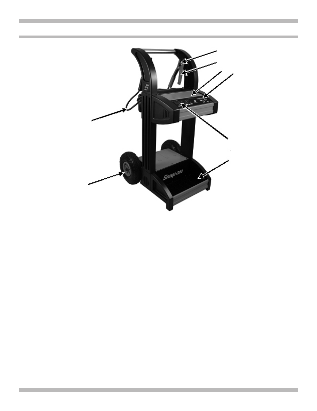
FEATURES
3
5
4
2
6
1
8
7
1. Digital Display
2. Control Panel
3. Clamp Storage Posts with Built-in Cable Wraps
4. Covered Tool Storage Compartment
5. Heavy-Duty Battery Clamps
6. 90-inch (228.6 cm) Extended Reach Output Cables
7. 10-inch (25.4 cm) dia. Pneumatic Tires
8. Booster pack or Auxiliary Battery Storage
EEBC500-INT-Z
• 6 •
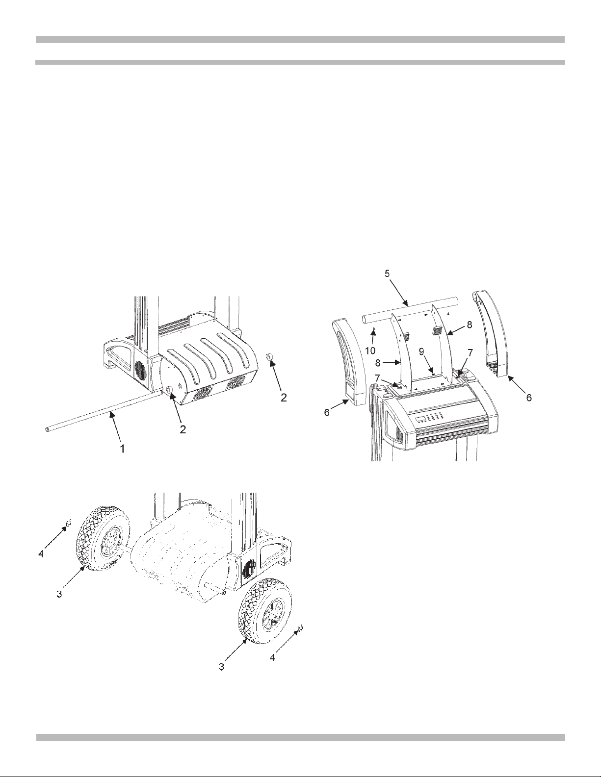
ASSEMBLING YOUR CHARGER
It is important to fully assemble your charger before use.
Follow these instructions for easy assembly.
TOOLS NEEDED
Phillips Head Screwdriver
Needle Nose Pliers
INSTALL AXLE AND WHEELS
Slide the axle (Item 1) through the bottom housing until it 1.
goes through the other side. It should self-align, but may
require some assistance.
Slide a spacer (Item 2) onto each end of the axle.2.
Slide a wheel (Item 3) onto each end of the axle shaft, 3.
and fasten everything using an E-clip (Item 4) on each
end.
INSTALL HANDLE
Slide the shaft (Item 5) into one of the handles (Item 6), 1.
followed by sliding each handle into the top base, making
sure the handles guide into the tracks of the legs.
Fasten each handle with a ¼” self-tapping screw (Item 7) 2.
on each side.
Install each cover (item 8) with four self-tapping screws 3.
(Item 9).
Secure the handle using two self-tapping screws (Item 4.
10) to prevent rotation.
For best results from your battery charger, learn to use it
properly. This section tells how to set the controls, charge
a battery in or out of the vehicle, use the ENGINE START
feature, test the battery, test alternator performance, and set
up for ash reprogramming.
EEBC500-INT-Z
• 7 •

A B
C
D
E F
BATTERY CHARGER CONTROLS
G
CONTROLS AND INDICATORS
[A] Digital Display – Gives a digital indication of voltage, %
of charge, or time, depending on the Display Mode chosen.
[B] Up/Down Arrows (switches) – Used to change any
variable settings on the display.
[C] Power ON/OFF (switch) – Controls the charging output
of the unit.
[D] Display Mode (switch) – Switches the display between
VOLTS – BATTERY % - ALT % - or TIME.
[E] Battery Voltage (switch) – Select from 6V, 12V, 24V, or to
do Flash Reprogramming.
[F] Battery Type (switch) – Select from Standard, AGM
or Gel type of battery being charged. Also used to enter
manual mode.
[G] Charge Rate (switch) - Select from Trickle Charge (max
4 amp rate), Fast Charge (max 15 amp rate), Rapid Charge
(max 60 amp rate), and Engine Start (max 300 amp rate).
REPROGRAMMING THE DEFAULTS
Charger Start-up Mode defaults. If you are satised with the
default settings, skip to Automatic Charging section.
The rst time you power up the charger, the default settings
are set to:
DISPLAY MODE – VOLTS
BATTERY VOLTAGE – 12V
BATTERY TYPE – STANDARD
CHARGE RATE – RAPID
To change the power up default settings:
Change to the desired DISPLAY MODE, BATTERY 1.
VOLTAGE, BATTERY TYPE, and CHARGE RATE.
Press and hold both Up and Down Arrow switches at the 2.
same time until the LED’s stop ashing.
The next time you power up the unit, these settings will 3.
be saved and become the startup default settings.
AUTOMATIC CHARGING
Set Battery VOLTAGE to 6V, 12V, or 24V.1.
Set BATTERY TYPE to STANDARD, AGM, or GEL CELL. 2.
If unsure, consult the label on the battery or the battery
manufacturer.
Set CHARGE RATE to TRICKLE, FAST, or RAPID – 3.
smaller batteries (lawn tractor, motorcycle, etc.) should
not be set on RAPID.
Charging will start when the ON/OFF button is pressed 4.
and nish automatically.
CHARGED (green) LED will light when nished and 5.
charger will maintain battery.
NOTE: For a battery with a starting voltage under one volt,
use manual mode rst to pre-charge the battery for ve
minutes, to get additional voltage into the battery for the
charger to analyze.
MANUAL CHARGING
Set Battery VOLTAGE to 6V, 12V, or 24V.1.
Set BATTERY TYPE to MANUAL.2.
Set CHARGE RATE to TRICKLE, FAST, or RAPID – 3.
smaller batteries (lawn tractor, motorcycle, etc.) should
not be set to RAPID.
Use the “UP” and “DOWN” buttons to adjust the charge 4.
time (shown on digital display).
EEBC500-INT-Z
• 8 •

ENGINE START
Follow the instructions for connecting the charger to 1.
the battery and power source in the “Connecting the
Charger” section.
Set the Battery VOLTAGE to 6V or 12V, (24V is not 2.
available).
Set the CHARGE RATE to ENGINE START.3.
NOTE: The charger will supply a 20-amp charge to the
battery before cranking.
Crank the vehicle. The charger will automatically cut out 4.
after a maximum of ve seconds.
NOTE: During extremely cold weather, or if the battery is
under one volt, charge the battery for ve minutes before
cranking the engine.
Wait three minutes before attempting to start again. The 5.
digital display will indicate the time remaining before
cranking again and the ENGINE START LED will be
blinking.
NOTE: During this cool down period, the charger is
supplying the battery with a 4-amp charge.
When the digital display times down to 6. 0 and reads
, the ENGINE START LED has stopped blinking and
the CHARGING LED is on, you are ready to crank the
vehicle again.
If the engine still does not start, allow the charger to 7.
charge the battery for ve more minutes before cranking
it again.
After the engine starts, unplug the charger power cord 8.
from the wall outlet, before disconnecting from the
battery.
IMPORTANT – Do not try to start the engine without
a battery in it. You could cause damage to the vehicle
electrical system.
If the engine does turn over, but never starts, there is not
a problem with the starting system; there is a problem
somewhere else with the vehicle. STOP cranking the engine
until the other problem has been diagnosed and corrected.
FLASH REPROGRAMMING
NOTE: Do not attempt to Flash Reprogram a vehicle that
has a discharged or defective battery. Make sure that the
vehicle battery is in good condition and fully charged before
proceeding.
Set BATTERY VOLTAGE to FLASH REPROGRAMMING.1.
Use “UP” and “DOWN” buttons to adjust voltage to the 2.
voltage needed for the vehicle being programmed (refer
to OEM specications). Voltage selected is shown on the
digital display. The unit has a voltage range of 13 to 14.8,
with a default of 14.2.
NOTE: When the VOLTS LED stops blinking, the display
shows the selected voltage.
Press ON/OFF to activate the output.3.
NOTE: During this time, the other buttons will not work
until you turn off the output. When the display shows
no buttons will work for ve seconds, then it automatically
goes back to the default state.
When nished with Flash Reprogramming, press ON/4.
OFF to exit this mode.
BATTERY PERCENTAGE
Press the display mode button to switch from battery voltage
to battery % of charge.
ALTERNATOR PERFORMANCE CHECK
Set DISPLAY MODE to ALT %.1.
With vehicle engine running, the digital display will 2.
indicate approximate alternator/battery voltage as percent
of normal (100% is normal). If the percentage is low or
high, a problem is indicated. Use an alternator tester for
further diagnosis.
EEBC500-INT-Z
• 9 •

CONNECTING THE CHARGER
CONNECTING TO A BATTERY IN THE VEHICLE
A SPARK NEAR THE BATTERY MAY CAUSE A BATTERY
EXPLOSION. TO REDUCE THE RISK OF A SPARK NEAR
THE BATTERY:
See OPERATING INSTRUCTIONS for length of charge 1.
information.
Arrange the power cord and charging leads carefully in 2.
order to avoid damage that could be caused by the hood,
door or moving engine parts.
Keep clear of the fan blades, belts, pulleys and other 3.
parts that can cause injury.
Check the polarity of the battery posts using the 4.
identication marks on the battery case: POSITIVE (POS,
P, +) and NEGATIVE (NEG, N, -). NOTE: On top-post
batteries, the positive battery terminal usually has a
larger diameter post than the negative one.
Identify which battery post is grounded or connected to 5.
the chassis. The negative post is NORMALLY the one
that is grounded.
To charge a negative-grounded system: Connect the red 6.
(POSITIVE) charger clamp to the ungrounded POSITIVE
(POS, P, +) post of the battery. Next, connect the black
(NEGATIVE) clamp to an unpainted, heavy metal part of
the chassis or engine block, away from the battery. Do
not connect clamp to carburetor, fuel lines, or sheet metal
parts.
To charge a positive-grounded system: Connect the 7.
black (NEGATIVE) charger clamp to the ungrounded
NEGATIVE (NEG, N, -) post of the battery. Then connect
the red (POSITIVE) clamp to an unpainted, heavy
metal part of the chassis or engine block, away from the
battery. Do not connect clamp to carburetor, fuel lines or
sheet metal parts.
WARNING: User and bystander must
wear safety goggles and protective gloves,
while making connections.
Twist or rock clamps back and forth to make a solid 8.
connection. This will help make better contact and help
keep them from slipping off and causing sparks.
Plug the power cord into a grounded AC outlet.9.
10. Adjust settings and charge battery.
11. When you are nished with the charger, turn the
POWER switch to the OFF position and unplug the
charger power cord.
12. Standing away from the battery, remove the charger
clamps in this order: (1) from the chassis connection and,
(2) from the battery post or terminal.
13. Clean and store the battery charger in a dry location.
CONNECTING TO A BATTERY OUT OF THE VEHICLE
A SPARK NEAR THE BATTERY MAY CAUSE A BATTERY
EXPLOSION. TO REDUCE THE RISK OF A SPARK NEAR
THE BATTERY:
Make sure all of the accessories and lights are turned 1.
off in the vehicle. Remove the battery from vehicle,
disconnecting the grounded terminal rst.
Check the polarity of the battery posts as indicated on 2.
the battery case: POSITIVE (POS, P, +) and NEGATIVE
(NEG, N, -). NOTE: On top-post batteries, the positive
battery terminal usually has a larger diameter post than
the negative one.
Connect the red (POSITIVE) charger clamp to the 3.
POSITIVE post of the battery. Be sure to rock the clamp
back and forth to make a solid connection.
Attach a six (AWG) or four (SAE) gauge insulated battery 4.
cable of at least 24 inches in length to the NEGATIVE
battery post. This cable will provide a safer connection
because arcing and sparking will occur away from the
battery. (The battery cable is not provided with the
charger, but may be purchased at most automotive
accessory outlets.)
Standing as far away from the battery as possible, 5.
connect the black (NEGATIVE) lead of the charger to the
free end of the cable. Rock the clamp to make a solid
connection.
WARNING: User and bystander must wear
safety goggles and protective gloves while
making connections.
Plug the power cord into a grounded AC outlet.6.
Adjust settings and charge battery.7.
When the battery is fully charged, turn the POWER 8.
switch to the OFF position and unplug the charger power
cord.
When disconnecting charger, always do so in reverse 9.
order of connecting procedure and break the rst
connection while as far away from the battery as
practical.
10. A marine (boat) battery must be removed and charged
on shore. To charge it onboard requires equipment
specially designed for marine use.
11. Clean and store the battery charger in a dry location.
EEBC500-INT-Z
• 10 •

CALCULATING CHARGE TIMES
The Chart Method
Use the following table to more accurately determine the
time it will take to bring a battery to full charge. First, identify
where your battery ts into the chart.
Small batteries – motorcycle, garden tractors, etc. – are •
usually rated in Ampere Hours (AH). For example: 6, 12,
32 AH etc.
Batteries in cars and smaller trucks are usually rated in •
Reserve Capacity (RC), Cold-Cranking Amps (CCA), or
both.
BATTERY SIZE/RATING
SMALL
BATTERIES
CAR/
TRUCKS
Motorcycle, garden tractor, etc.
200 - 315 CCA 40 - 60 RC 11 - 14 60 - 90 min. 20 - 30 min.
315 - 550 CCA 60 - 85 RC 14 - 18 90 - 120 min. 30 - 40 min.
550 - 1000 CCA 85 - 190 RC 18 - 35 2 - 3.5 45 - 60 min.
MARINE/DEEP CYCLE
6 - 12 AH 2 - 4 NR NR
12 - 32 AH 4 - 10 NR NR
80 RC 18 105 min. NR
140 RC 27 2 hrs, 45 min. NR
160 RC 30 3 NR
180 RC 33 3.5 NR
Marine or deep-cycle batteries are usually rated in •
Reserve Capacity (RC).
NR means that the charger setting is NOT •
RECOMMENDED.
Find your battery rating on the chart below and note the
charge time given for each charger setting. The times
given are for batteries with a 50-percent charge prior to
recharging. Add more time for severely discharged batteries.
CHARGE RATE/CHARGING TIME IN HOURS
(unless otherwise stated)
4 AMP 15 AMP 60 AMP
The Hydrometer or Electronic Method
To nd the time needed to fully charge your battery,
determine the battery’s charge level with a hydrometer or
electronic Percent-of-Charge Tester. The following table will
help you convert hydrometer readings to percent of charge
values.
SPECIFIC
GRAVITY
1.265 100% 0%
1.225 75% 25%
1.155 25% 75%
1.120 0% 100%
PERCENT OF
CHARGE
PERCENT OF CHARGE
NEEDED
When you know the percent of charge and the Amp
Hour (AH) rating of your battery, you can calculate the
approximate time needed to bring your battery to a full
charge.
To convert Reserve Capacity to Amp Hours, divide Reserve
Capacity by 2, and add 16:
Example:
Amp Hour Rating = Reserve Capacity + 16
2
NOTE: The reserve Capacity can be obtained from the
battery specication sheet or the owner’s manual.
To calculate time needed for a charge:
Find the percent charge needed. (A battery at 50% •
charge that will be charged to 100% needs another 50%
(.50)).
Multiply the Amp Hour rating by the charge needed (.50) •
and divide by the charger setting (4, 15, or 60 amps).
Multiply the results by 1.25 and you will have the total •
time needed, in hours, to bring the battery to full charge.
Add one additional hour for a deep-cycle battery.•
Example:
Amp Hour Rating x % of charge needed x 1.25 = hours of charge
Charger Setting
100 (AH Rating) x .50 (charge needed) x 1.25 = 3.125 hours
20 (Charger Setting)
100 x .50 x1.25 = 3.125
20
You would need to charge your 100-Ampere Hour Battery
for a little more than three hours at the 20-Amp charge rate
using the above example.
EEBC500-INT-Z
• 11 •

MAINTENANCE, CARE AND STORAGE
A minimal amount of care can keep your battery charger
working properly for years.
After each use, unplug unit, wipe all battery corrosion 1.
and other dirt or oil from clamps, cables, and the charger
case. Use a dry cloth.
Coil the charger cables in the built in cable wraps to 2.
prevent damage. This will prevent accidental damage to
the cables and charger.
Have any cracked or frayed cables replaced by an 3.
authorized Snap-on representative.
Store the unplugged battery charger in a clean, dry area.4.
EEBC500-INT-Z
• 12 •

TROUBLESHOOTING
Performance problems often result from little things that you can x yourself. Please read through this table for a possible
solution if a problem occurs.
PROBLEM POSSIBLE CAUSE SOLUTION/REASONS
No reading on the display
or “Connected” LED is not
on.
Short or no start cycle
when cranking engine.
Charger makes a loud
buzz or hum.
Display reading stays high. Battery severely discharged.
Charger is connected
correctly but charging is
not taking place.
Clicking noise from
charger.
“Charging” LED is ashing. The battery is sulfated. A sulfated battery will eventually take a normal charge if left
Clamps are not making a good connection.
AC cord and/or extension cord is loose.
No power at receptacle.
Clamp polarity reversed.
Failure to wait 3 minutes (180 seconds)
between cranks.
Clamps are not making a good connection.
AC cord and/or extension cord is loose.
No power at receptacle.
The charger may be heated up.
Battery may be severely discharged.
Transformer laminations vibrate (buzz). No problem, this is a normal condition.
Wrong battery voltage selected.
Battery is severely discharged. If your battery does not have one volt, you need to switch to the
Circuit breaker is cycling (manual mode
only).
Battery is defective.
Shorted battery clamps.
Severely discharged battery, but otherwise
a good battery.
Reverse connections at battery.
Check for poor connection at battery and frame. Make sure
connecting points are clean.
Check power cord and extension cord for loose tting plug.
Check for open fuse or circuit breaker supplying AC outlet.
Verify and reverse the battery clamps.
Wait three minutes or until the display reads and the Charging
LED is on.
Check for poor connection at battery and frame. Make sure
connecting points are clean.
Check power cord and extension cord for loose tting plug.
Check for open fuse or circuit breaker supplying AC outlet.
The internal thermal protector may have tripped and needs a little
longer to close. Wait until it automatically resets and try again.
On a severely discharged battery, charge for 10 to 15 minutes in
the 15 amp manual rate to help assist in cranking.
Continue charging battery for two more hours. If problem
continues; call your Snap-on representative.
Make sure BATTERY VOLTAGE switch is properly set for 6V, 12V
or 24V selection.
Manual mode for a few minutes until the charging begins and then
switch back to Automatic mode in the desired charge rate.
The settings may be wrong. Check the charger settings.
Have the battery checked.
Circuit breaker cycles when current draw is too high.
Check for shorted cables and replace if necessary.
Allow charging to continue until battery has a chance to recover
sufciently to take a charge. If more than 20 minutes, stop
charging and have the battery checked.
Correct the lead connections.
connected. The charger will continue to charge with a low current
for up to 10 hours to recover the battery. If the battery will not take
a charge after 10 hours, have it checked.
EEBC500-INT-Z
• 13 •
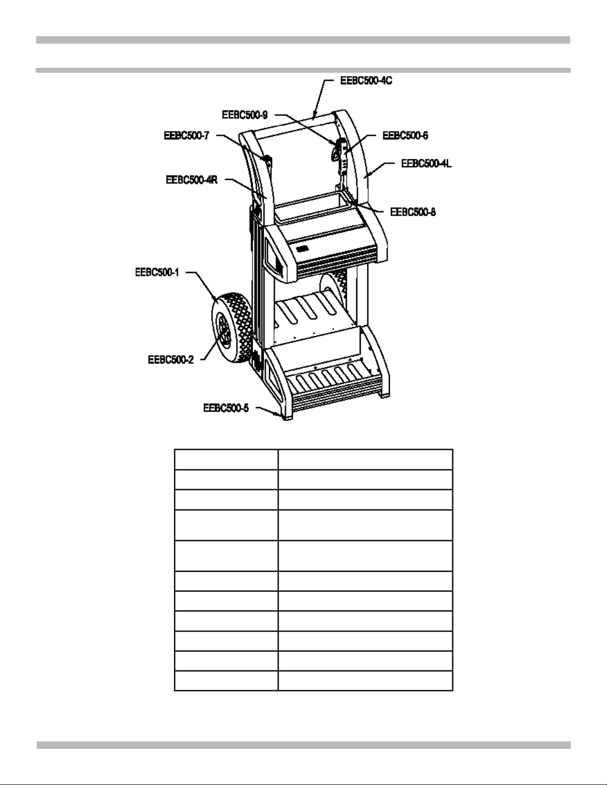
REPLACEMENT PARTS LIST - DIAGRAM
Stock Number Description
EEBC500-1 Replacement Wheel w/snap ring
EEBC500-2 Axle
EEBC500-4L
EEBC500-4R
EEBC500-4C Center Handle Bar
EEBC500-5 Front Foot w/hardware
EEBC500-6 Positive Cable Assembly
EEBC500-7 Negative Cable Assembly
EEBC500-8 Parts Storage Compartment
EEBC500-9 Clamps Posts (2)
Replacement Left Handle
Support w/hardware
Replacement Right Handle
Support w/hardware
EEBC500-INT-Z
• 14 •
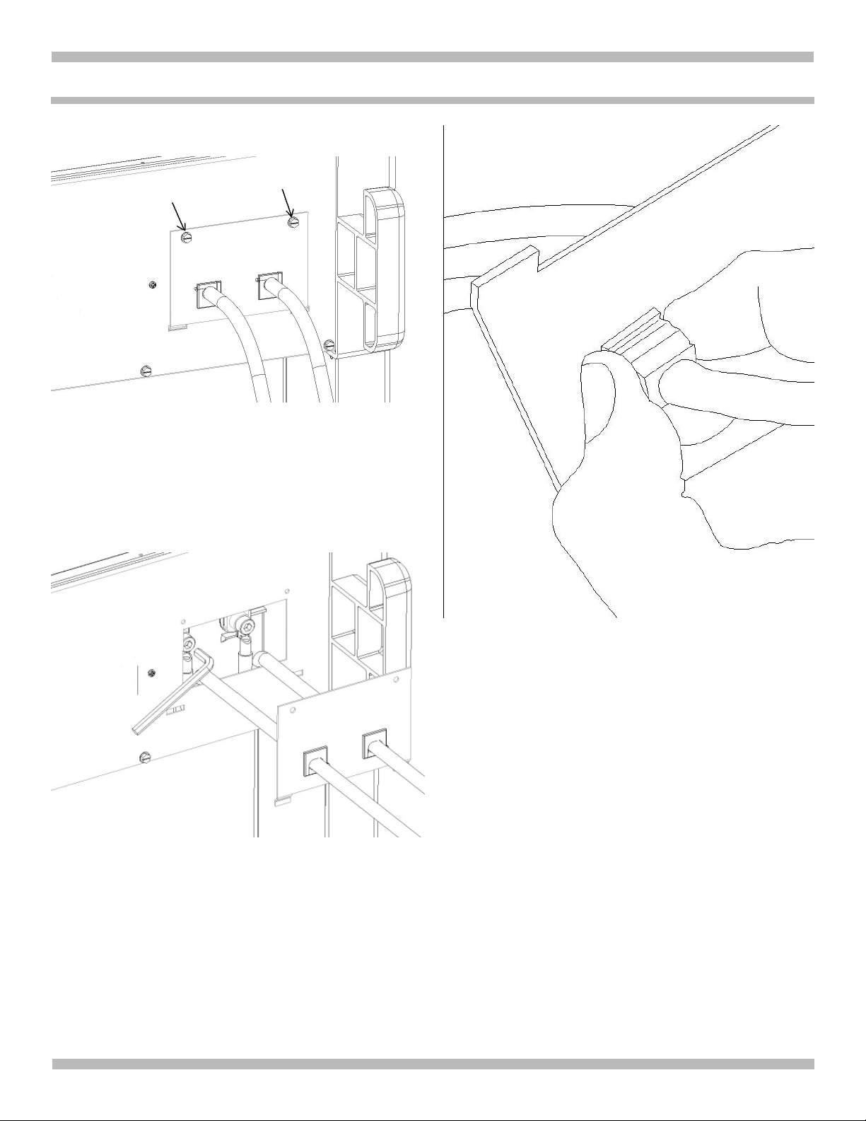
REPLACING THE CLAMP CABLES
Remove the two screws on the cover plate, and tilt it out 1.
of the slots on the bottom.
2. Remove the screws on the terminals using a 6 mm hex
wrench. These will be torqued down tight, so you will
probably need to use the long end. Take care when
removing the screws to prevent stripping the hole. To
prevent damage, it is recommended you use an open
ended wrench to keep the terminal from spinning.
3. The strain reliefs are held in by three spring tabs. While
pulling on the cable (opposite side of strain relief), push
on the bottom tab to get it out rst, then squeeze the two
side tabs together to remove the strain relief from the
hole.
4. Follow these steps in reverse to assemble the new cable.
EEBC500-INT-Z
• 15 •
 Loading...