

Page 1

TigerSwitch 16
Intelligent bandwidth acceleration for workgroups
Ethernet and Fast Ethernet Workgroup Switches
◆ Three models, each with 16 10BASE-T ports plus:
◆ Two 100BASE-TX ports
◆ Two 100BASE-FX ports
◆ One 100BASE-TX port and one 100BASE-FX port
◆ Manageable in-band via SNMP, RMON and Telnet
User Guide
Page 2

USER GUIDE
FOR SMC’S
TIGERSWITCH 16
FAMILY
July 1997
Pub. # 900.185 Rev. A
Standard Microsystems Corporation
80 Arkay Drive
Hauppauge, New York 11788
Page 3

Information furnished by Standard Microsystems Corporation
(SMC) is believed to be accurate and reliable. However, no
responsibility is assumed by SMC for its use, nor for any
infringements of patents or other rights of third parties which
may result from its use. No license is granted by implication or
otherwise under any patent or patent rights of SMC. SMC
reserves the right to change specifications at any time without
notice.
Copyright © 1997 by
Standard Microsystems Corporation
Hauppauge, New York.
All rights reserved. Printed in U.S.A.
Trademarks:
SMC and Standard Microsystems are registered trademarks; and EliteView, EtherEZ,
EtherPower, EZ Hub, TigerStack and TigerSwitch are trademarks of Standard Microsystems
Corporation. Other product and company names are trademarks or registered trademarks
of their respective holders.
Page 4

Limited Warranty
HARDWARE: Standard Microsystems Corporation (“SMC”) warrants these
TigerSwitch 16 units to be free from defects in workmanship and materials,
under normal use and service, for the following length of time from the date of
purchase from SMC or its Authorized Reseller:
TigerSwitch 16 Units . . . . . . . . . . . . . . . . . . . . . . . . . . . . . . . . .Three Years
If a product does not operate as warranted during the applicable warranty
period, SMC shall, at its option and expense, repair the defective product or
part, deliver to Customer an equivalent product or part to replace the defective
item, or refund to customer the purchase price paid for the defective product.
All products that are replaced will become the property of SMC. Replacement
products may be new or reconditioned. Any replaced or repaired product or
part has a ninety (90) day warranty or the remainder of the initial warranty
period, whichever is longer.
SMC shall not be responsible for any custom software or firmware, configuration information, or memory data of Customer contained in, stored on, or
integrated with any products returned to SMC pursuant to any warranty.
SOFTWARE: SMC warrants that the software programs licensed from it will
perform in substantial conformance to the program specifications for a period
of ninety (90) days from the date of purchase from SMC or its Authorized
Reseller. SMC warrants the magnetic media containing software against failure
during the warranty period. No updates are provided. SMC’s sole obligation
hereunder shall be (at SMC’s discretion) to refund the purchase price paid by
Customer for any defective software products or to replace any defective media
with software which substantially conforms to SMC’s applicable published specifications. Customer assumes responsibility for the selection of the appropriate
applications program and associated reference materials. SMC makes no warranty that its software products will work in combination with any hardware or
applications software products provided by third parties, that the operation of
the software products will be uninterrupted or error free, or that all defects in
the software products will be corrected. For any third party products listed in
the SMC software product documentation or specifications as being compatible,
SMC will make reasonable efforts to prove compatibility, except where the
non-compatibility is caused by a “bug” or defect in the third party’s product.
STANDARD WARRANTY SERVICE: Standard warranty service for hardware
products may be obtained by delivering the defective product, accompanied
by a copy of the dated proof of purchase, to SMC’s Service Center or to an
Authorized SMC Service Center during the applicable warranty period. Standard
warranty service for software products may be obtained by telephoning SMC’s
Service Center or an Authorized SMC Service Center, within the warranty
period. Products returned to SMC’s Service Center must be pre-authorized by
Page 5

LIMITED WARRANTY
SMC with a Return Material Authorization (RMA) number marked on the outside of the package, and sent prepaid, insured, and packaged appropriately for
safe shipment. The repaired or replaced item will be shipped to Customer, at
SMC’s expense, not later than thirty (30) days after receipt by SMC.
WARRANTIES EXCLUSIVE: IF AN SMC PRODUCT DOES NOT OPERATE AS
WARRANTED ABOVE, CUSTOMER’S SOLE REMEDY SHALL BE REPAIR,
REPLACEMENT OR REFUND OF THE PURCHASE PRICE PAID, AT SMC’S
OPTION. THE FOREGOING WARRANTIES AND REMEDIES ARE EXCLUSIVE
AND ARE IN LIEU OF ALL OTHER WARRANTIES OR CONDITIONS, EXPRESS
OR IMPLIED, EITHER IN FACT OR BY OPERATION OF LAW, STATUTORY OR
OTHERWISE, INCLUDING WARRANTIES OR CONDITIONS OF MERCHANTABILITY AND FITNESS FOR A PARTICULAR PURPOSE. SMC NEITHER
ASSUMES NOR AUTHORIZES ANY OTHER PERSON TO ASSUME FOR IT ANY
OTHER LIABILITY IN CONNECTION WITH THE SALE, INSTALLATION, MAINTENANCE OR USE OF ITS PRODUCTS.
SMC SHALL NOT BE LIABLE UNDER THIS WARRANTY IF ITS TESTING AND
EXAMINATION DISCLOSE THE ALLEGED DEFECT IN THE PRODUCT DOES
NOT EXIST OR WAS CAUSED BY CUSTOMER’S OR ANY THIRD PERSON’S
MISUSE, NEGLECT, IMPROPER INSTALLATION OR TESTING, UNAUTHORIZED
ATTEMPTS TO REPAIR, OR ANY OTHER CAUSE BEYOND THE RANGE OF
THE INTENDED USE, OR BY ACCIDENT, FIRE, LIGHTNING, OR OTHER
HAZARD.
LIMITATION OF LIABILITY: IN NO EVENT, WHETHER BASED IN CONTRACT
OR TORT (INCLUDING NEGLIGENCE) SHALL SMC BE LIABLE FOR INCIDENTAL, CONSEQUENTIAL, INDIRECT, SPECIAL, OR PUNITIVE DAMAGES OF
ANY KIND, OR FOR LOSS OF REVENUE, LOSS OF BUSINESS, OR OTHER
FINANCIAL LOSS ARISING OUT OF OR IN CONNECTION WITH THE SALE,
INSTALLATION, MAINTENANCE, USE, PERFORMANCE, FAILURE, OR INTERRUPTION OF ITS PRODUCTS, EVEN IF SMC OR ITS AUTHORIZED RESELLER
HAS BEEN ADVISED OF THE POSSIBILITY OF SUCH DAMAGES. NOTHING
HEREIN SHALL HAVE THE EFFECT OF LIMITING OR EXCLUDING SMC’S
LIABILITY FOR DEATH OR PERSONAL INJURY CAUSED BY NEGLIGENCE.
Some states do not allow the exclusion of implied warranties or the limitation
of incidental or consequential damages for consumer products, so the above
limitations and exclusions may not apply to you. This warranty gives you specific legal rights which may vary from state to state. Nothing in this warranty
shall be taken to affect your statutory rights.
Standard Microsystems Corporation
80 Arkay Drive
Hauppauge, NY 11788
516-273-3100
Page 6

TABLE OF CONTENTS
Compliances.......................................................... v
1 Quick Start...................................................... 1-1
Introduction ......................................................................... 1-2
Connecting the Switch......................................................... 1-3
Configuring the Switch for SNMP and Telnet
Management .................................................................... 1-5
2 About the Switches ........................................ 2-1
Overview.............................................................................. 2-3
Features and Benefits.......................................................... 2-12
Switch Architecture.............................................................. 2-13
Switch Operation................................................................. 2-15
Management Options .......................................................... 2-16
3 Planning......................................................... 3-1
Benefits of Switching........................................................... 3-2
Segmenting the Network..................................................... 3-4
Full-Duplex Operation ........................................................ 3-5
Sample Applications............................................................ 3-6
4 Installing ........................................................ 4-1
Selecting a Site..................................................................... 4-2
Equipment Checklist............................................................ 4-3
Mounting.............................................................................. 4-4
Connecting to the Console Port.......................................... 4-6
Connecting to a Power Source ........................................... 4-7
Diagnostic Self-Tests............................................................ 4-8
Making Network Connections ............................................ 4-9
Default Settings.................................................................... 4-13
i
Page 7

TABLE OF CONTENTS
5 Configuring and Monitoring ........................ 5-1
The Console Interface ......................................................... 5-3
Typical Configuration Operations ...................................... 5-25
Typical Monitoring Operations........................................... 5-32
Using Telnet......................................................................... 5-34
Using SLIP............................................................................ 5-35
6 Managing Via SNMP and RMON.................... 6-1
SNMP Protocol..................................................................... 6-2
Using RMON........................................................................ 6-3
MIB Objects ......................................................................... 6-3
A Cables ............................................................. A-1
Specifications ....................................................................... A-2
10BASE-T/100BASE-TX Pin Assignments........................... A-3
Serial Console Port Pin Assignments.................................. A-5
B Specifications................................................. B-1
Specifications ....................................................................... B-2
C Sample Configuration ................................... C-1
Introduction ......................................................................... C-2
Windows Terminal............................................................... C-3
D Troubleshooting ............................................ D-1
Troubleshooting Chart......................................................... D-2
ii
Page 8

TABLE OF CONTENTS
List of Figures
Figure 1-1. Main Menu....................................................... 1-4
Figure 1-2. Switch Configuration Menu ............................ 1-5
Figure 1-3. IP Configuration Menu.................................... 1-6
Figure 1-4. SNMP Configuration Menu.............................. 1-7
Figure 2-1. TigerSwitch 16 Model SMC6516TT with
two 100BASE-TX Ports..................................................... 2-3
Figure 2-2. TigerSwitch 16 Model SMC6516FF with
two 100BASE-FX Ports..................................................... 2-3
Figure 2-3. TigerSwitch 16 Model SMC6516TF with
one 100BASE-TX Port and one 100BASE-FX Port.......... 2-3
Figure 2-4. 10BASE-T Ports................................................ 2-5
Figure 2-5. SMC6516FF with 100BASE-FX Ports............... 2-6
Figure 2-6. RJ-45 Integrated LEDs...................................... 2-7
Figure 2-7. Vertical LED Array and Port Select Button..... 2-8
Figure 2-8. Console Port and Reset Button....................... 2-9
Figure 2-9. Power Supply Receptacles.............................. 2-10
Figure 2-10. Power Supply LEDs........................................ 2-10
Figure 3-1. Single-Segment LAN........................................ 3-6
Figure 3-2. Microsegmented LAN...................................... 3-7
Figure 3-3. Switched LAN .................................................. 3-8
Figure 3-4. Sample Application with Model SMC6516TT. 3-9
Figure 3-5. Sample Application with Model SMC6516TF. 3-10
Figure 3-6. Sample Application with Model SMC6516FF. 3-11
Figure 4-1. Attaching the Brackets .................................... 4-4
Figure 4-2. Installing the Switch in a Rack........................ 4-5
Figure 4-3. Attaching the Adhesive Feet........................... 4-5
Figure 4-4. Console Port .................................................... 4-6
Figure 4-5. Power Receptacles........................................... 4-7
Figure 4-6. Diagnostics Display......................................... 4-8
iii
Page 9

TABLE OF CONTENTS
Figure 4-7. Connecting Fiber Cable................................... 4-12
Figure 5-1. Main Menu....................................................... 5-4
Figure 5-2. Switch Configuration Menu ............................ 5-5
Figure 5-3. Configuration Display Screen ......................... 5-7
Figure 5-4. IP Configuration Menu.................................... 5-9
Figure 5-5. SNMP Configuration Menu.............................. 5-11
Figure 5-6. Spanning Tree Configuration Menu ............... 5-12
Figure 5-7. Address Aging Configuration Menu ............... 5-13
Figure 5-8. Port Mirroring Configuration Menu................ 5-14
Figure 5-9. Port Configuration Menu................................. 5-15
Figure 5-10 Port Summary Display Screen........................ 5-16
Figure 5-11. Port Summary Configuration Menu.............. 5-17
Figure 5-12. Port [x] Configuration Menu.......................... 5-18
Figure 5-13. Statistics Menu ............................................... 5-19
Figure 5-14. Utilities Menu................................................. 5-20
Figure 5-15. Console Configuration Menu........................ 5-22
Figure 5-16. Boot Menu ..................................................... 5-23
Figure 5-17. Telnet Menu................................................... 5-24
Figure 5-18. TFTP Loader Menu........................................ 5-30
Figure 5-19. IP Configuration Menu.................................. 5-35
Figure A-1. RJ-45 Connector Pin Numbers........................ A-3
iv
Page 10

COMPLIANCES
FCC A
This equipment generates, uses, and can radiate radio frequency energy and, if
not installed and used in accordance with the instruction manual, may cause
interference to radio communications. It has been tested and found to comply
with the limits for a Class A computing device pursuant to Subpart B of Part 15
of FCC Rules, which are designed to provide reasonable protection against such
interference when operated in a commercial environment. Operation of this
equipment in a residential area is likely to cause interference, in which case the
user, at his own expense, will be required to take whatever measures may be
required to correct the interference.
Canada Department of Communications - Class A
This digital apparatus does not exceed the Class A limits for radio noise emissions from digital apparatus as set out in the interference-causing equipment
standard entitled "Digital Apparatus", ICES-003 of the Department of
Communications.
Cet appareil numérique respecte les limites de bruits radioélectriques applicables aux appareils numériques de Classe A prescrites dans la norme sur le
matériel brouilleur : "Appareils Numériques", NMB-003 édictée par le ministère
des Communications.
EC Conformity
This information technology product was found to comply with EC General
Directives 89/336/EEC and 73/23/EEC. An EC Declaration of Conformity was
issued for this product by:
Standard Microsystems (Europe) Limited
1st Floor, Pyramid House, Easthampstead Road
Bracknell, Berkshire RG12 1NS, United Kingdom
Japan VCCI Class 1
Australia AS/NZS 3548 (1995)
SMC contact for products in Australia is:
SMC Australia Pty. Ltd., ACN 069 351 613
LVL 66 MLC Center
Martin Place
Sydney NSW 2000
Phone: 61-2-9238-2206
Fax: 61-2-9238-2220
v
Page 11

CHAPTER 1
QUICK START
Introduction . . . . . . . . . . . . . . . . . . . . . . . . . 1-2
Connecting the Switch . . . . . . . . . . . . . . . . . . 1-3
Configuring the Switch for SNMP and Telnet
Management . . . . . . . . . . . . . . . . . . . . . . . . . 1-5
1-1
Page 12

QUICK START
Introduction
SMC’s TigerSwitch™16 family consists of a set of three manageable Ethernet switches with Fast Ethernet connection capability.
Each switch provides sixteen 10BASE-T ports for connection to
Ethernet hubs, servers and workstations. Each switch also
includes two ports for connection to Fast Ethernet devices. The
switch, depending on the model chosen, will contain either two
100BASE-TX ports, two 100BASE-FX ports or one 100BASE-TX
port and one 100BASE-FX port. The Fast Ethernet port types
found on each model are listed below:
◆ Model SMC6516TT
• two 100BASE-TX ports with Auto-Negotiation
◆ Model SMC6516FF
• two 100BASE-FX ports
◆ Model SMC6516TF
• one 100BASE-TX port with Auto-Negotiation
• one 100BASE-FX port
This chapter provides a set of instructions designed to help you
get up and running quickly and without excessive details. The
steps in each of the two sections refer to other locations in the
manual where further information may be found.
The first section, “Connecting the Switch,” provides a list of
instructions for powering up the switch and making network
connections, and also for setting up a PC to configure and
monitor the switch out-of-band.
The second section, “Configuring the Switch for SNMP and
Telnet Management,” discusses the steps required to set up the
switch for in-band management.
1-2
Page 13

Connecting the Switch
1. Power up the PC to be used to configure and monitor the
switch out-of-band. After loading this PC with communications software, set your terminal or communications program
to the following parameters: 9600, n, 8, 1 (9600 baud, no
parity, 8 data bits, 1 stop bit). (See Appendix C for the
Windows Terminal program parameter settings.)
2. Plug the female end of a DB-9 standard null-modem cable
into the Console connector on the front panel of the switch.
Attach the other end of the cable to the serial connector on
the PC (typically COM1 or COM2). (See “Connecting to the
Console Port” in Chapter 4.)
3. Connect one end of the 3-pin AC power cord supplied with
the switch to the power receptacle on the rear of the chassis,
and the other end to a grounded power outlet. (See
“Connecting to a Power Source” in Chapter 4.) Make note of
the diagnostic test results that appear on the PC attached to
the Console port.
QUICK START
4. If you have purchased a Redundant Power Unit (RPU), plug
the 14-pin connector from the RPU cable into the mating
connector on the rear panel of the switch. (See the guide
supplied with the RPU.)
5. Connect the front-panel 10BASE-T ports to hubs, servers and
power users. Once a valid connection has been made, the
green LED above the port will light. (See “Making Network
Connections” in Chapter 4.)
6. Connect each front-panel 100BASE-TX and 100BASE-FX port
to a Fast Ethernet power user, server, workgroup or backbone. When a valid connection has been made, the green
LED for that port will light. (See “Making Network
Connections” in Chapter 4.)
1-3
Page 14

QUICK START
7. Press the Esc key on the terminal or PC. The Main Menu
will appear on the screen.
___________________________________________________
>>>> Main Menu <<<<
1. Switch Configuration Menu
2. Port Configuration Menu
3. Statistics Menu
4. Utilities Menu
5. Exit Menus (Password Protect)
Enter Selection:
___________________________________________________
Figure 1-1. Main Menu
You may now set a variety of configuration options, such as fullduplex mode on the 10BASE-T ports, a password for the
Console interface, and Spanning Tree and Address Aging parameters. You may also select various options for monitoring the
performance of the unit out-of-band. These are described in
Chapter 5.
To set up the unit for in-band management via SNMP or Telnet,
continue with Step 8.
1-4
Page 15

Configuring the Switch for
SNMP and Telnet Management
8. To assign an IP address, or to have one assigned automatically, select “Switch Configuration Menu” from the Main
Menu. The Switch Configuration Menu will appear.
___________________________________________________
>>>> Switch Configuration Menu <<<<
1. Configuration Summary
2. IP Configuration
3. SNMP Configuration
4. Spanning Tree Configuration
5. Address Aging Configuration
6. Port Mirroring Configuration
<ESC> To Exit Menu
Enter Selection:
___________________________________________________
Figure 1-2. Switch Configuration Menu
QUICK START
9. DHCP is enabled by default. If you have a DHCP server, an
IP address and Subnet Mask are assigned automatically.
Make a note of the IP address and skip to Step 12.
Otherwise, select “IP Configuration” from the menu. The IP
Configuration Menu will appear (see Figure 1-3).
10. To manually enter the IP address of the switch, you must
first disable DHCP. Then, select “Switch IP Address” from
the menu and enter the address to be assigned to the switch.
This should be an administratively assigned address. (See
“Configuring the IP Address” in Chapter 5.)
11. Select “Subnet Mask” from the menu and enter the subnet
mask for the IP address entered in Step 10. If applicable,
also enter the Gateway IP address.
1-5
Page 16

QUICK START
___________________________________________________
>>>> IP Configuration Menu <<<<
1. Automatic Selection of IP Address (DHCP).. [ ON]
2. Switch IP Address.. ............. [ 170.129. 78. 28 ]
3. Default SNMP Manager IP Address.. [ 170.129. 78.208 ]
4. Default Gateway IP Address....... [ 170.129. 78. 1 ]
5. Subnet Mask...................... [ 255.255.255. 0 ]
6. SLIP Enable...................... [ Disabled ]
7. SLIP IP Address.................. [ 0. 0. 0. 0 ]
8. SLIP Subnet Mask..... ........... [ 255. 0. 0. 0 ]
<ESC> To Exit Menu
Enter Selection:
___________________________________________________
Figure 1-3. IP Configuration Menu
12. For Telnet Management: Connect to the IP address
assigned in Step 10. Installation is complete.
13. For SNMP Management: Check to be sure the manage-
ment console and the switch use the same SNMP read-only
and write community names. For the switch, both names
are factory-set to “public.” If the name “public” is also used
for both management console names, connect to the IP
address assigned in Step 10 and then skip to Step 15.
Otherwise, continue with Step 14.
14. If the community names need to be changed, press the Esc
key to return to the Switch Configuration Menu (see Figure
1-2). Then select “SNMP Configuration” to display the SNMP
Configuration Menu (see Figure 1-4).
15. Select “SNMP Get Community Name” from the menu and
enter the new read-only access community name (up to 10
alphanumeric characters). Then, select “SNMP Set
Community Name” and enter the new write access commu-
1-6
Page 17

QUICK START
nity name (up to 10 alphanumeric characters).
___________________________________________________
>>>> SNMP Configuration Menu <<<<
1. SNMP Get Community Name ( 10 characters max ).....[ public ]
2. SNMP Set Community Name ( 10 characters max ).....[ public ]
3. System Location ( 24 characters max ).. [ ]
4. System Name ( 24 characters max )...... [ ]
5. System Contact ( 24 characters max )... [ ]
<ESC> To Exit Menu
Enter Selection:
___________________________________________________
Figure 1-4. SNMP Configuration Menu
16. Compile the MIB file into the SNMP network management
platform. This file, supplied with the switch on a 3.5 inch
floppy diskette, provides access to the private MIB extensions for the switch. Installation is complete.
1-7
Page 18

CHAPTER 2
ABOUT THE SWITCHES
Overview . . . . . . . . . . . . . . . . . . . . . . . . . . . 2-3
Ports and Status LEDs . . . . . . . . . . . . . . . . 2-5
10BASE-T Ports . . . . . . . . . . . . . . . . . . . 2-5
100BASE-TX Port(s) . . . . . . . . . . . . . . . . 2-5
100BASE-FX Port(s) . . . . . . . . . . . . . . . . 2-6
Link and Select LEDs . . . . . . . . . . . . . . . 2-7
Shared Vertical LED Array and
Port Select Button . . . . . . . . . . . . . . . . . 2-8
Console Port . . . . . . . . . . . . . . . . . . . . . . . 2-9
Reset Button . . . . . . . . . . . . . . . . . . . . . . . 2-9
Optional Redundant Power Unit . . . . . . . . 2-9
Power Supply Receptacles and Status LEDs 2-10
Features and Benefits . . . . . . . . . . . . . . . . . . . 2-12
Switch Architecture . . . . . . . . . . . . . . . . . . . . 2-13
Buffered Switching . . . . . . . . . . . . . . . . . . 2-13
Automatic Address Learning . . . . . . . . . . . . 2-13
Spanning Tree Protocol . . . . . . . . . . . . . . . 2-14
Switch Operation . . . . . . . . . . . . . . . . . . . . . . 2-15
Diagnostic Tests . . . . . . . . . . . . . . . . . . . . 2-15
Software Downloads . . . . . . . . . . . . . . . . . 2-15
2-1
Page 19

ABOUT THE SWITCHES
Non-volatile Parameter Storage . . . . . . . . . 2-15
Management Options . . . . . . . . . . . . . . . . . . . 2-16
Serial Console Interface . . . . . . . . . . . . . . . 2-16
Telnet . . . . . . . . . . . . . . . . . . . . . . . . . . . . 2-16
SNMP . . . . . . . . . . . . . . . . . . . . . . . . . . . . 2-17
2-2
Page 20

ABOUT THE SWITCHES
Overview
SMC’s TigerSwitch 16 is a family of intelligent Ethernet workgroup switches that offers both an increase in network
performance plus an economical solution for anyone planning
to integrate Fast Ethernet into their Ethernet LAN. In addition to
sixteen 10BASE-T ports, these switches provide two Fast
Ethernet ports. Depending on the model chosen, the switch
will include either two 100BASE-TX ports with Auto-Negotiation,
two 100BASE-FX ports or one 100BASE-TX port with AutoNegotiation and one 100BASE-FX port.
The three TigerSwitch 16 models are shown below:
Figure 2-1. TigerSwitch 16 Model SMC6516TT with
two 100BASE-TX Ports
Figure 2-2. TigerSwitch 16 Model SMC6516FF with
two 100BASE-FX Ports
Figure 2-3. TigerSwitch 16 Model SMC6516TF with
one 100BASE-TX Port and one 100BASE-FX Port
2-3
Page 21

ABOUT THE SWITCHES
The Fast Ethernet ports on each switch are contained in a single, dual-port replaceable module.* This modular design allows
you the option of installing different types of Fast Ethernet
ports, according to your changing network needs.
The available slide-in replacement modules are listed below:
Slide-in Fast Ethernet Modules
Model Ports
100BASE-TX 100BASE-FX
SMC6016TT 20
SMC6016FF 02
SMC6016TF 11
All the switches employ a buffered “store-and-forward” architecture that performs error checking to prevent bad packets from
being propagated throughout the network. Their non-blocking
design allows simultaneous wire-speed transport of multiple
packets at consistently low latency on all ports. And, they
feature full-duplex operation to double the bandwidth of those
desktop and switch connections.
In addition to “at-a-glance” LEDs, these switches feature an
integrated scalable management set that includes out-of-band
management via an RS-232 console port, in-band management
via Telnet or any SNMP-based manager, support for 4-group
RMON, and Port Mirroring for full RMON support with an
external probe or for traffic analysis via any network lanalyzer.
This enables you to choose the level of management that’s right
for you.
The TigerSwitch 16 family also supports an optional Redundant
Power Unit to minimize downtime in the event of an internal
power supply or AC circuit failure.
* Note: The switch will not POST (Power On Self-Test) without a
module installed.
2-4
Page 22
ABOUT THE SWITCHES
Ports and Status LEDs
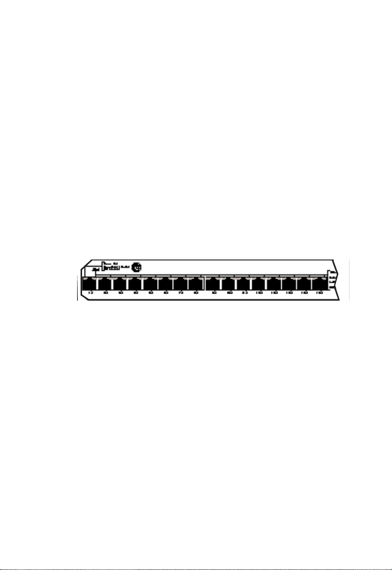
10BASE-T Ports
The sixteen 10BASE-T ports are located on the front panel of
each switch. These ports are labeled with an “x” to indicate that
they have a built-in crossover.*
If a 10BASE-T port is connected directly to an Ethernet server,
power user or another switch, it will provide the device with a
dedicated bandwidth—20 Mbps in full-duplex mode or 10 Mbps
in half-duplex mode. If the port is connected to an Ethernet
hub, it will provide the hub with a 10 Mbps bandwidth that can
be shared by multiple users.
Figure 2-4. 10BASE-T Ports
100BASE-TX Port(s)
Models SMC6516TT and SMC6516TF are equipped with at least
one 100BASE-TX port (port 18). Port 17 on model SMC6516TT
is another 100BASE-TX port.
Like the 10BASE-T ports, each 100BASE-TX port is labeled with
an “x” to indicate that it has a built-in crossover.* In addition,
the 100BASE-TX ports support Auto-Negotiation, so the optimum
operating mode—half or full duplex and 10 or 100 Mbps—is
selected automatically.
* Workstations and servers can be connected to these ports with
straight-through cable. When connecting hubs and other switches to
these ports, a crossover cable will probably be necessary. Please see
Appendix A for cabling information.
2-5
Page 23

ABOUT THE SWITCHES
When connected to a 10BASE-T device, the port will operate at
10 Mbps, providing each switch with an additional Ethernet port
(two ports on the SMC6516TT). When connected to a 100BASETX device, the port will operate at the higher data rate, allowing
for the easy integration of Fast Ethernet into an Ethernet LAN.
If a 100BASE-TX port is connected directly to a Fast Ethernet
server, power user or another switch, it will provide the device
with a dedicated bandwidth—200 Mbps in full-duplex mode or
100 Mbps in half-duplex mode. If the port is connected to a
Fast Ethernet hub, it will provide the hub with a 100 Mbps
bandwidth that can be shared by multiple users.
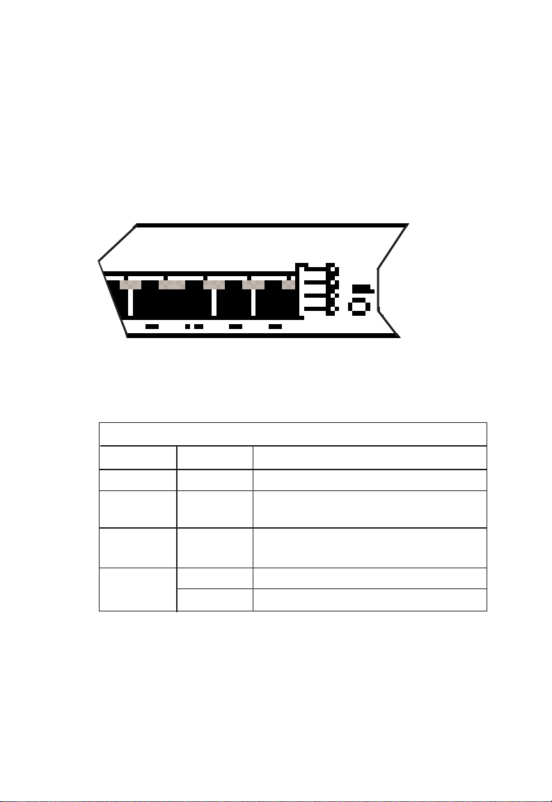
100BASE-FX Port(s)
Ports 17 and 18 on TigerSwitch 16 model SMC6516FF and port
17 on model SMC6516TF are 100BASE-FX ports with SC connectors. In full-duplex mode, these ports can be connected to a
corporate backbone or central site with up to 2 km of fiber
cable.
Figure 2-5. SMC6516FF with 100BASE-FX Ports
2-6
Page 24
ABOUT THE SWITCHES
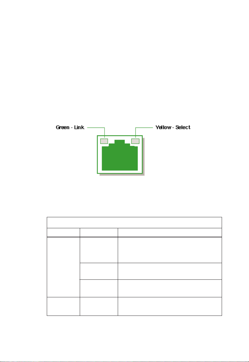
Link and Select LEDs
Each of the RJ-45 connectors on the 10BASE-T and 100BASE-TX
ports has dual integrated LEDs. The left LED displays the port’s
Link status. If this LED is lit (green), it indicates that the connection between the port and the attached device is good. The
right LED, when lit (yellow), indicates that the full status of the
port (Receive, Collision, Full Duplex and 100 Mbps data rate) is
displayed by the shared vertical LED array (see “Shared Vertical
LED Array and Port Select Button” on the next page).
Figure 2-6. RJ-45 Integrated LEDs
The 100BASE-FX ports have individual Link and Select LEDs that
perform the same functions.
The Link and Select LEDs are described in the following table:
Link and Select LEDs
Function Condition Description
Link Off Port is not in use, attached device is
not powered on, or port has been
disabled via SNMP or Console port
Blinking* Connection between port on switch
and attached device is bad
Green Connection between port on switch
and attached device is good
Select Y ellow Port is selected to drive the vertical
LED array
*Note: The Link LEDs on unconnected ports will blink approximately
once every 5 seconds. This blinking reflects background diagnostics
run automatically by the switch and is not indicative of any error.
2-7
Page 25
ABOUT THE SWITCHES
Shared V ertical LED Array and Port Select Button
At power-up, the shared vertical LED array displays the status of
port 1. To display the status of port 2, press the Port Select button located to the right of the array. Repeated depressions of
this button will cycle through all eighteen ports.
Figure 2-7. Vertical LED Array and Port Select Button
The vertical LED array is described in the following table:
Vertical LED Array
Function Condition Description
Receive Green Data is being received
Collision Yellow Two or more devices on the segment
are transmitting at the same time
Full Yellow Port configured for full-duplex
Duplex operation (available on all ports)
100 Mbs Yellow Port is operating at 100 Mbps data rate
Off Port is operating at 10 Mbps data rate
2-8
Page 26

ABOUT THE SWITCHES
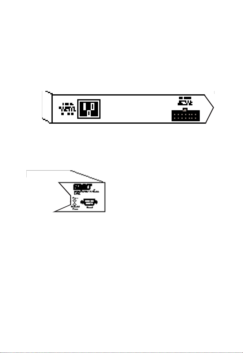
Console Port
Each switch contains a Console port on the front panel. This is
an RS-232 serial port with a DB-9 connector. When connected
to a PC, this port can be used to configure the switch and to
monitor the switch out-of-band and in-band via Telnet.
Figure 2-8. Console Port and Reset Button
Reset Button
The front panel of each switch contains a Reset button. This
button is used to restart the switch. It has almost the same
effect as powering the switch off and on again. The only
difference is that the internal diagnostics which are initiated at
power up are not executed on reset.
Optional Redundant Power Unit
SMC’s Redundant Power Units (RPUs) are separate devices and
each has its own own power cord. These devices can supply
power to the switch in the event of a failure of the internal
power supply. Contact your reseller for advice regarding the
appropriate RPU for your specific application.
2-9
Page 27
ABOUT THE SWITCHES
Power Supply Receptacles and Status LEDs
There are two power receptacles on the rear of each switch.
The standard receptacle labeled “Power” is for the AC power
cord. The 14-pin receptacle labeled “DC Input” is for the
optional Redundant Power Unit (RPU).
Figure 2-9. Power Supply Receptacles
Power and RPU LEDs located on the front panel of each switch
indicate the status of both the internal and redundant power
supplies. These LEDs are described on the following page.
Figure 2-10. Power Supply LEDs
2-10
Page 28

ABOUT THE SWITCHES
Power Supply Status LEDs
LED Condition
Power Redundant Status
Power
Off Off No AC power
Green Off Internal power supply is operating
properly; redundant power supply
is not present or has been
disconnected
Green Green Both internal and redundant power
supplies are operating properly
Red Green Internal power supply has failed;
device is being powered by
redundant power supply
Red Off Redundant power supply has
failed; device is being powered by
internal power supply
2-11
Page 29

ABOUT THE SWITCHES
Features and Benefits
• IEEE 802.3 and 802.3u compliance ensures compatibility
with standards-based hubs, adapters and switches from any
vendor
• Non-blocking architecture allows multiple simultaneous
switching paths for increased throughput
• Filters and forwards at line-rate speed on all ports for high
performance
• “Store-and-forward” switch design increases reliability of
transmission by checking each packet for validity before forwarding it to its destination
• Automatic address learning with user-defined aging eliminates need to configure addresses manually
• 8,192 entry address table can store addresses for moderate
to large size networks
• SNMP agent for management by SMC’s EliteView™or any
other SNMP-based application
• RS-232 Console port simplifies switch configuration and
allows switch to be managed out-of-band
• 4-group RMON support - Event, Alarm, Statistics and History
groups - for pro-active management
• Port Mirroring for full RMON support with external probe or
for traffic analysis with network lanalyzer
• Spanning Tree Protocol adds fault tolerance by allowing
redundant paths to be created between LAN segments
• Software downloads to Flash ROM via TFTP or Console port
• Optional Redundant Power Unit (attached to a separate
circuit) minimizes downtime in the event of an internal
power supply failure
• Replaceable dual-port Fast Ethernet modules for added
flexibility
2-12
Page 30

ABOUT THE SWITCHES
Switch Architecture
Buffered Switching
Each TigerSwitch 16 unit is a “store-and-forward” device. Every
packet it receives is stored in a buffer so it can be checked for
validity before being forwarded to another port. In addition, the
switches feature a non-blocking design that allows simultaneous
wire-speed transport of multiple packets at consistently low
latency.
Automatic Address Learning
An aggregate address table that can hold 8,192 entries is
provided for learning, filtering and forwarding. Addresses are
automatically learned by each TigerSwitch 16 unit and maintained in the address table to enable the switch to perform filtering and forwarding at line-rate speeds. When a packet containing a destination address that does not appear in the table is
encountered, the packet is broadcast to all segments.
Packets are filtered if their destination address is on the same
segment as their source address. By confining network traffic to
its respective collision domain, filtering reduces the overall traffic on the network.
2-13
Page 31

ABOUT THE SWITCHES
Spanning Tree Protocol
The TigerSwitch 16 family supports the IEEE 802.1d Spanning
Tree Protocol. This protocol adds a level of fault tolerance by
allowing two or more redundant connections to be created
between a pair of LAN segments. When there are multiple
physical paths between segments, the protocol can choose a
single path at any given time and disable all others. This
prevents network traffic from circulating in an endless loop.
However, if the chosen path fails for any reason, an alternate
path will be activated to maintain the connection.
The default factory setting for Spanning Tree Protocol is
“enabled.” This protocol can be configured (enabled and dis-
abled) out-of-band via the serial console interface or in-band via
SNMP or Telnet.
2-14
Page 32

ABOUT THE SWITCHES
Switch Operation
Diagnostic Tests
Diagnostic tests are performed whenever the switch is powered
up or reset. Upon power-up, the test results are displayed on
the PC attached to the Console port. During the test sequence,
the switch detects whether or not the software is loaded. If it is,
the Main Menu is displayed. Otherwise, the Boot Loader Menu
is displayed so that new software can be downloaded.
Note: Diagnostics are not displayed when the Reset Button is
pressed.
Software Downloads
Software is downloaded into a single 256 KB Flash ROM on the
switch. The software can be downloaded in-band via TFTP or
out-of-band via the RS-232 Console port. (See “Downloading
New Software” in Chapter 5.)
Non-volatile Parameter Storage
Important operating parameters, such as IP address, Spanning
Tree configuration, and management security parameters, are
stored in non-volatile Flash memory and retain their values
during a power failure.
Note: Since RMON parameter settings and learned addresses
are not stored in non-volatile RAM, these values are not
retained during a power failure. They are cleared
whenever the switch is reset.
2-15
Page 33

ABOUT THE SWITCHES
Management Options
The TigerSwitch 16 family can be managed using any one of the
following three methods:
• out-of-band via the RS-232 console interface
• in-band via Telnet
• in-band via any SNMP-based network manager
Serial Console Interface
The switches can be managed out-of-band via the RS-232 console port. This requires a PC running a terminal application
such as Windows Terminal. An RS-232 standard null-modem
cable with a DB-9 connector is used to connect the device to
the Console port on the switch. (See “Connecting to the
Console Port” in Chapter 4 for detailed instructions.)
This interface operates at 9600 (default value) or 19,200 baud
and can be password-protected. (See Chapter 5, “Configuring
and Monitoring,” for information on out-of-band management.)
Telnet
The switches can also be managed in-band via a Telnet connection using TCP/IP protocol. The Telnet user interface is menudriven and the switch’s operating parameters can be passwordprotected. (See Chapter 5, “Configuring and Monitoring,” for
information on in-band management via Telnet.)
2-16
Page 34

ABOUT THE SWITCHES
SNMP
In addition, the switches can be managed in-band from a workstation using EliteView or any other SNMP-based manager.
Simple Network Management Protocol (SNMP), the most popular management protocol in use today, defines the structure of
information maintained on a device being managed, and the
operations used to access the information. SNMP provides two
levels of management security protection based on community
names. The SNMP Get community name provides read-only
access to the information, while the SNMP Set community name
enables you to modify the information. See Chapter 6,
“Managing Via SNMP” for information on in-band SNMP
management.
2-17
Page 35

CHAPTER 3
PLANNING
Benefits of Switching . . . . . . . . . . . . . . . . . . . 3-2
Switched Ethernet — Multiple
Simultaneous Data Streams . . . . . . . . . . . . 3-2
Switched Fast Ethernet — High-Speed
Data Pipes . . . . . . . . . . . . . . . . . . . . . . . . . 3-3
Switching — an Evolutionary Step . . . . . . . 3-3
Segmenting the Network . . . . . . . . . . . . . . . . 3-4
Client/Server . . . . . . . . . . . . . . . . . . . . . . . 3-4
Backbone Connections . . . . . . . . . . . . . . . 3-4
Full-Duplex Operation . . . . . . . . . . . . . . . . . . 3-5
Sample Applications . . . . . . . . . . . . . . . . . . . 3-6
Shared Ethernet LAN . . . . . . . . . . . . . . . . . 3-6
Segmented Ethernet LAN . . . . . . . . . . . . . . 3-7
Switched Ethernet LAN . . . . . . . . . . . . . . . 3-8
Integrating Ethernet and Fast Ethernet . . . . 3-9
TigerSwitch 16 Model SMC6516TT . . . . . 3-9
TigerSwitch 16 Model SMC6516TF . . . . . 3-10
TigerSwitch 16 Model SMC6516FF . . . . . 3-11
3-1
Page 36

PLANNING
Benefits of Switching
Ethernet is traditionally a shared technology. Its media
(network cable) is shared, so only one transmission can take
place at a time. Its 10 Mbps bandwidth is shared too, so as
more users are added to the network, there is less available
bandwidth for each user. In addition to increased traffic,
Ethernet performance is also impacted by server bottlenecks,
and by the requirements of high-performance workstations and
high-bandwidth applications, such as those supporting multimedia and workgroup collaboration. The result is decreased
network performance.
Network congestion can be relieved by microsegmentation.
This technique divides the network into individual segments
(collision domains). With fewer users on a segment competing
for the same 10 Mbps bandwidth, there is more bandwidth
available for each user. However, these segments must be
interconnected in order to communicate with one another.
Switches are the preferred method of interconnecting these
separate segments. They are more economical than bridges and
routers. They also offer higher performance, since the packet
latency of switches is considerably lower than that of bridges
and routers. And, the network upgrade is easier, faster and
less disruptive. Switches require at most only minimal reconfiguration, so there is less network downtime. Switches also
isolate network traffic, so problems on one segment, such as
faulty wiring and jabbering nodes, will not affect the rest of the
network.
Switched Ethernet — Multiple Simultaneous
Data Streams
Switches have multiple ports that are capable of transmitting
and receiving information simultaneously at full wire speed.
They integrate and build upon multi-port bridging functionality,
creating an engine powerful enough to microsegment the LAN
3-2
Page 37

PLANNING
into multiple collision domains, yet cost-effective enough to
allow users to dedicate bandwidth to workstations, file servers
and print servers.
At the desktop level, switches can replace Ethernet hubs. By
providing servers and high-performance workstations with dedicated 10 Mbps LAN connections, switches boost the throughput
and performance of bandwidth intensive applications, such as
imaging, CAD/CAM and relational database access.
At the workgroup level, switches can coexist with Ethernet
hubs. Cascading the hubs to switches, rather than to each other,
reduces the number of users on each segment. This boosts network performance and increases the bandwidth per user.
Switched Fast Ethernet — High-Speed Data Pipes
Further bandwidth gains can be attained through the use of Fast
Ethernet technology, which provides a 10-fold increase in the
data rate per segment. Switching technology enables the seamless integration of Ethernet and Fast Ethernet LANs, while
preserving the basic network operation and frame format. By
adjusting the mix of shared and switched Ethernet and Fast
Ethernet ports, a truly scalable plan can be developed for every
LAN configuration — one that is capable of providing the
necessary amount of bandwidth to each location.
Switching — an Evolutionary Step
The introduction of switching technology into Ethernet networks is an evolutionary step. Ethernet switches allow
companies to preserve their investment in the current network
infrastructure. They increase the bandwidth and performance
of the network without requiring costly changes to LAN cabling
or replacement of network cards, applications and the network
operating system.
3-3
Page 38

PLANNING
Segmenting the Network
Each port on a switch is a separate segment, so when implementing switching, you must decide how to segment the
network. For desktop switching, the decision is easy, as each
PC is on a separate segment. For segment switching, it is a
good idea to investigate the traffic flow on the network and the
interactions of the applications being used. Keep in mind that
since a switch allows conversations between pairs of ports to
take place concurrently, it is most effective when packet
exchanges are distributed over multiple switch ports.
Client/Server
On a Client/Server network, all conversations take place
between a user and a server. If there is one server on the network, only one conversation can take place at a time, so the
server will still be a bottleneck. Connecting this server directly
to the switch will improve response time. And, adding more
servers will increase the number of simultaneous conversations
that can take place.
Backbone Connections
A switch can be used in a collapsed backbone application to
interconnect network segments and provide access to file
servers and other switches. Workgroup hubs, connecting multiple stations and/or other hubs, are provided with a single
switch connection, while servers are given their own dedicated
switch port. Routers and other networking devices can also be
connected to the collapsed backbone.
3-4
Page 39

Full-Duplex Operation
Full duplex is a transmission method that allows a network
device to transmit and receive concurrently. This mode is supported by some 10BASE-T and 100BASE-TX switches and network cards, but not by hubs or by 100BASE-T4 devices.
Connecting a pair of devices that can operate in full-duplex
mode eliminates collisions and effectively doubles the bandwidth of that segment. In addition, full-duplex operation can
also be used to extend Fast Ethernet fiber cabling distances.
PLANNING
3-5
Page 40

PLANNING
Sample Applications
Sample applications are provided below. They show how
switching technology can increase the performance of a shared
Ethernet Client/Server LAN without extensive network reconfiguration and changes to the infrastructure.
Shared Ethernet LAN
In the traditional Client/Server LAN, all the workstations and
servers are connected to stackable and/or standalone hubs. As
additional workgroups are added to the LAN, hubs are added to
accommodate them. The 10 Mbps bandwidth is shared by all.
The following figure represents a single-segment LAN. Servers
and workstations with SMC’s EtherEZ™ISA network cards are
connected to a stack of SMC’s TigerStack™hubs.
Figure 3-1. Single-Segment LAN
3-6
Page 41

Segmented Ethernet LAN
To reduce contention, the network is segmented into separate
repeater groups. This enables the workstations on each
segment to share the 10 Mbps bandwidth of that segment.
Reducing the number of stations on each segment decreases
the amount of collisions that occur as a matter of course on a
conventional shared Ethernet LAN when traffic is heavy. Note
that stations on the same segment can communicate only with
one another; there is no communication between segments.
Since each SMC Tigerstack hub can be segmented into two to
four repeater groups, the stack of eight TigerStack hubs shown
below can be subdivided into as many as 32 independent LAN
segments (separate 10 Mbps collision domains) with an aggregate bandwidth potential of 320 Mbps.
TigerStack
PLANNING
Segments 1-32
Figure 3-2. Microsegmented LAN
3-7
Page 42

PLANNING
Switched Ethernet LAN
To enable the segments to communicate with one another, they
are interconnected through a switch. Switches, like hubs, can
be cascaded to interconnect additional segments.
In the figure shown below, six TigerStack segments are interconnected via an 8-port Ethernet switch. The remaining two
10BASE-T ports on the switch are configured for full-duplex
operation. This provides them both with 20 Mbps of bandwidth. One of these ports is connected directly to a server and
the other, to another Ethernet switch to provide additional ports
for the stack segments.
Figure 3-3. Switched LAN
3-8
Page 43

Integrating Ethernet and Fast Ethernet
Some Ethernet switches also have one or two Fast Ethernet
ports. These ports can be used to integrate Fast Ethernet into
an Ethernet network.
TigerSwitch 16 Model SMC6516TT
This TigerSwitch 16 model contains two 100BASE-TX ports.
Each Fast Ethernet port can be connected to a Fast Ethernet
hub, to a server containing a Fast Ethernet network card such as
SMC’s EtherPower™II 10/100 PCI card, or to a 100BASE-TX port
on another switch. For desktop and switch connections, the
ports can be configured for full-duplex operation.
In the following figure, one 100BASE-TX port is connected to
SMC’s TigerSwitch 100 (an 8-port Fast Ethernet switch) and the
other 100BASE-TX port to a server. Note that two PCs are connected directly to 10BASE-T ports on the TigerSwitch 16, providing each power user with 20 Mbps of aggregate bandwidth
in full-duplex mode. The aggregate bandwidth of the entire
network is 580 Mbps.
PLANNING
Figure 3-4. Sample Application with Model SMC6516TT
3-9
Page 44

PLANNING
TigerSwitch 16 Model SMC6516TF
This model contains one 100BASE-TX port and one 100BASE-FX
port. The 100BASE-FX port can be used to connect the switch
to a 100BASE-FX port on another switch or hub, making it part
of a high-speed fiber backbone. The longer allowable run
distance for fiber cable also makes the 100BASE-FX port useful
for connecting to remote devices. The 100BASE-TX port can be
used to provide a dedicated bandwidth (200 Mbps in full-duplex
mode) to a server or power user that is close to the switch.
In the following figure, the 100BASE-FX port is connected to a
remote central site and the 100BASE-TX port, to a server. The
aggregate bandwidth of this network is 580 Mbps.
Figure 3-5. Sample Application with Model SMC6516TF
3-10
Page 45

PLANNING
TigerSwitch 16 Model SMC6516FF
This model contains two 100BASE-FX ports. When configured
for full-duplex operation, these 100BASE-FX ports can be connected to other devices with up to 2 km of fiber cable. This
allows the user to take advantage of a significantly higher maximum cable run distance than that available for other media.
The following figure shows the 100BASE-FX ports on an
SMC6516FF switch connected to the 100BASE-FX ports on other
TigerSwitch units, making it the central link in a 200 Mbps
network backbone. The 100BASE-TX ports on the other
switches, also configured in full duplex mode, are dedicated to
servers. The aggregate bandwidth of the network is 1.28 Gbps.
Figure 3-6. Sample Application with Model SMC6516FF
3-11
Page 46

CHAPTER 4
INSTALLING
Selecting a Site . . . . . . . . . . . . . . . . . . . . . . . 4-2
Equipment Checklist . . . . . . . . . . . . . . . . . . . 4-3
Package Contents . . . . . . . . . . . . . . . . . . . 4-3
Required Rack-Mounting Equipment . . . . . 4-3
Mounting . . . . . . . . . . . . . . . . . . . . . . . . . . . 4-4
Rack Mounting . . . . . . . . . . . . . . . . . . . . . 4-4
Desktop or Shelf Mounting . . . . . . . . . . . . 4-5
Connecting to the Console Port . . . . . . . . . . . 4-6
Connecting to a Power Source . . . . . . . . . . . . 4-7
Diagnostic Self-Tests . . . . . . . . . . . . . . . . . . . 4-8
Making Network Connections . . . . . . . . . . . . 4-9
10 Mbps Ethernet Collision Domain . . . . . . 4-9
100 Mbps Fast Ethernet Collision Domain . 4-10
Twisted-Pair Devices . . . . . . . . . . . . . . . . . 4-11
Cabling Guidelines . . . . . . . . . . . . . . . . 4-11
Connecting Devices . . . . . . . . . . . . . . . . 4-12
100BASE-FX Devices . . . . . . . . . . . . . . . . . 4-12
Connecting Devices . . . . . . . . . . . . . . . . 4-12
Default Settings . . . . . . . . . . . . . . . . . . . . . . . 4-13
4-1
Page 47

INSTALLING
Selecting a Site
The TigerSwitch 16 family can be installed in a standard 19-inch
equipment rack or on a desktop or shelf. Be sure to follow the
guidelines below when choosing a location.
◆ The switch site should:
• be able to maintain its temperature within 0° to 50° C and
its humidity within 10% to 90%, non-condensing
• provide adequate space (approximately two inches) on
all sides for an air flow of 10 cubic feet/minute minimum
• be accessible for installing, cabling and maintaining the
switch
• allow the status LEDs to be clearly visible
◆ Make sure twisted-pair cable is always routed away from
power lines, fluorescent lighting fixtures and other sources
of electrical interference, such as radios, transmitters, etc.
◆ Make sure that a separate grounded power outlet that pro-
vides 120 to 240 VAC, 50 to 60 Hz, is within 8 feet (2.44 m)
of the hub. As with any equipment, using a filter or surge
suppressor is recommended.
4-2
Page 48

Equipment Checklist
After unpacking your switch, check the contents of the box
against the packing list below to be sure you’ve received all the
components.
Package Contents
In addition to this user guide, the package should contain:
◆ One TigerSwitch 16 switch
◆ Bracket Mounting Kit containing two brackets and four
screws for attaching the brackets to the switch
◆ Four adhesive feet
◆ Appropriate power cord(s)
◆ 3.5-inch disk containing the TigerSwitch 16 MIB
◆ SMC Warranty Registration Card — be sure to complete and
return this card within 90 days
Required Rack-Mounting Equipment
Be sure to have the following equipment available when mounting your switch in a rack:
INSTALLING
◆ Four rack-mounting screws with nuts — these are not pro-
vided with the switch
◆ A screwdriver (Phillips-head or flathead, depending on type
of screws used)
4-3
Page 49

INSTALLING
Mounting
A TigerSwitch 16 unit can be mounted in a standard 19-inch
equipment rack or on a desktop or shelf. Mounting instructions
for each type of site follow.
Rack Mounting
Before rack mounting the switch, pay particular attention to the
following factors:
◆ Temperature: Since the temperature within a rack assem-
bly may be higher than the ambient room temperature,
check that the rack-environment temperature is within the
specified operating temperature range.
◆ Mechanical Loading: Do not place any equipment on top
of a rack-mounted unit
◆ Circuit Overloading: Be sure that the supply circuit to the
rack assembly is not overloaded.
◆ Grounding: Rack-mounted equipment should be properly
grounded. Particular attention should be given to supply
connections other than direct connections to the AC power
mains.
To rack mount a switch:
1. Attach the brackets to the device using the screws provided
in the Bracket Mounting Kit.
Figure 4-1. Attaching the Brackets
4-4
Page 50

2. Mount the device in the rack, using four rack-mounting
screws and nuts (not provided).
Figure 4-2. Installing the Switch in a Rack
3. Turn to the section, “Connecting to the Console Port.”
Desktop or Shelf Mounting
1. Attach the four adhesive feet to the bottom of the switch.
INSTALLING
Figure 4-3. Attaching the Adhesive Feet
2. Set the switch on a flat surface near an AC power source,
making sure there are at least two inches of space on all
sides for proper air flow.
3. Turn to the next section, “Connecting to the Console Port.”
4-5
Page 51

INSTALLING
Connecting to the Console Port
Each TigerSwitch 16 model contains a Console port on the front
panel. This is an RS-232 serial port with a male DB-9 connector.
When connected to a PC, this port can be used to:
◆ Monitor the switch out-of-band
◆ Change the default configuration settings for specific
applications, for example:
• Assign an IP address for Telnet and SNMP management
• Set passwords for security reasons
Note: Access rights default to read/write. This means that
unauthorized users are able to make changes to the
configuration unless password protection is enabled.
Figure 4-4. Console Port
To make the connection:
1. Plug the female end of a standard RS-232 null-modem cable
into the switch connector labeled Console. Plug the other
end of the cable into the serial connector on the PC
(typically COM1 or COM2). See Appendix A for Console
connector pin assignments.
2. Power up the device and set the communications program to
the following parameters: 9600, n, 8, 1 (9600 baud, no parity,
8 bits, 1 stop bit).
If you are using the Windows Terminal program on a PC,
see Appendix C for a detailed description of the configuration parameters.
4-6
Page 52

Connecting to a Power Source
1. Plug one end of the appropriate power cable (see below)
into the back of the switch, and the other end into a
grounded, 3-pin socket.
For North American Use: Each switch is shipped with one
standard AC line cord for North America that is UL and CSA
approved.
For International Use: The International version of the
switch is shipped with AC line cords for Continental Europe
and the UK. If you need to change the line cord, you must
use a line cord set that has been approved for the receptacle
type in your country. Any cord used must be HAR-Certified,
and must have HAR stamped on the outside of the cord
jacket to comply with the CENELEC Harmonized Document
HD-21. The female receptacle must meet CEE-22 requirements and IEC 320-030 specifications.
INSTALLING
Figure 4-5. Power Receptacles
2. If you have purchased a Redundant Power Unit (RPU), plug
the 14-pin connector from the RPU into the mating connector on the rear panel of the switch (see the guide supplied
with the RPU).
3. The front-panel Power LED should be lit. If it isn’t, check to
make sure the power cable is plugged in correctly. For an
explanation of the Power and Redundant Power LEDs, refer
to “Power Supply Receptacles and Status LEDs” in Chapter 2.
4-7
Page 53

INSTALLING
Diagnostic Self-Tests
When the switch is powered up, diagnostic tests are performed,
and the test results are displayed on the PC attached to the
Console port.
___________________________________________________
SMC TigerSwitch 16
ROM Checksum . . . . . . . . . . . . .PASSED
Local RAM Test (Byte) . . . . . . . . .PASSED
Local RAM Test (Quad Word) . . . . . .PASSED
___________________________________________________
Figure 4-6. Diagnostics Display
During the test sequence, the switch detects whether the software is loaded. If it is, the Main Menu is displayed (see “Main
Menu” in Chapter 5). Otherwise, the Boot Loader Menu is displayed so that new software can be downloaded (see
“Downloading New Software” in Chapter 5).
4-8
Page 54

Making Network Connections
Switches are designed to interconnect multiple segments, or
collision domains. Each segment may contain a single server or
workstation, or multiple workstations that are connected to a
hub. An overview of the rules for both Ethernet and Fast
Ethernet collision domains is provided below.
10 Mbps Ethernet Collision Domain
SMC 5 - 4 - 3 Rule
Between any two PCs or other stations in the same 10 Mbps
collision domain, there may be:
• up to 5 cable segments in series,
• up to 4 repeaters (hubs),
• up to 3 populated cable segments, that is, segments
attached to two or more PCs (coax networks only).*
* The remaining two segments are unpopulated; these are
known as inter-repeater links or IRLs. This distinction
between populated and unpopulated segments is significant
for coax networks only.
INSTALLING
Maximum Cable Lengths
Cable Type Maximum Length
Twisted Pair, Categories 3, 4, 5 100 m (328 ft.)
Fiber (FOIRL) 1.0 km (0.62 mi.)
Fiber (10BASE-FL) 2.0 km (1.28 mi.)
Thin Coax 185 m (607 ft.)
Thick Coax 500 m (1,640 ft.)
AUI 50 m (165 ft.)
4-9
Page 55

INSTALLING
100 Mbps Fast Ethernet Collision Domain
SMC 3 - 2 Rule for Class IIRepeaters
Between any two PCs or other stations in the same
100BASE-T collision domain, there may be:
• up to 3 link segments and
• up to 2 Class II repeaters (hubs)
SMC 2 - 1 Rule for Class I and Class II Repeaters
Between any two PCs or other stations in the same
100BASE-T collision domain, there may be:
• up to 2 link segments and
• up to 1 Class I or Class II repeater (hub)
Maximum 100BASE-T Network Diameter*
Repeater Type Twisted Pair Twisted Pair/Fiber
and Number 100BASE-TX/T4 100BASE-T4/FX 100BASE-TX/FX
1 Class I 200 m (656 ft.) 231 m (757.7 ft.) 260.8 m (855.4ft.)
1 Class II 200 m (656 ft.) 304 m (997.1 ft.) 308.8 m (1012.9 ft.)
2 Class II 205 m (672.4 ft.) 236.3 m (775.1 ft.) 216.2 m (709.1 ft
.)
Maximum 100BASE-T Cable Distance
Cable Type Connecting Max. Distance
Twisted Pair Any two devices 100 m (328 ft.)
Fiber Switch to Switch, Server or PC
Half duplex 412 m (1,351.4 ft.)
Full duplex 2 km (1.24 mi.)
MII Any two devices 0.5 m (1.6 ft.)
*Note: Network Diameter is defined as the wire distance between two end stations in
the same collision domain.
4-10
Page 56

T wisted-Pair Devices
Each 10BASE-T and 100BASE-TX device requires an unshielded
twisted-pair (UTP) cable with RJ-45 connectors at both ends.
For 10BASE-TX connections, two pairs of Category 3, 4 or 5
cable are required. 100BASE-TX connections require two pairs
of certified Category 5 cable.
Cabling Guidelines
Every twisted-pair connection must have a wiring crossover to
transmit and receive data. For convenience, the crossover is
built into all ports that are labeled with an “x”—these are called
fixed crossover ports. Since network cards do not have a builtin crossover, PCs can be connected to these ports with straightthrough cable. See Appendix A for cabling pinouts.
Hubs (and other switches) may have either crossover or straightthrough ports. For this reason, the type of cable used to connect these devices to a TigerSwitch 16 unit is determined by the
port on the other device, as shown in the table below.
INSTALLING
Crossover/Straight-Through Wiring Requirements
The port on the If the hub or Then use...cable
TigerSwitch 16 is... switch port is...
Crossover (x) Crossover (x) Crossover
Crossover (x) Straight-through Straight-through
4-11
Page 57

INSTALLING
Connecting Devices
Servers, workstations, hubs and other switches can be connected to the switch with a twisted-pair cable segment. This
segment may be up to 100 m (328 feet) in length. Be sure to
use the appropriate type of cable (either crossover or straightthrough). Use only certified Category 5 cable for the 100BASETX connection.
Attach one end of the cable to an unused port on the switch,
and the other end to the RJ-45 port on the other device. As
each connection is made, the green LED above the port will
light (after 2-3 seconds) to indicate that the connection is valid.
100BASE-FX Devices
The 100BASE-FX connection requires 62.5/125 micron multimode fiber optic cabling with an SC connector. Since SC
connectors are keyed, the cable can be attached in only one
manner.
Connecting Devices
Connect one end of the cable to the SC connector on the front
panel of the switch (see illustration) and the other end to the
other device.
Figure 4-7. Connecting Fiber Cable
4-12
Page 58

Default Settings
Each switch is set to operate as a transparent bridge using the
default operating parameters. It will automatically learn the
addresses of all active stations on each segment and appropriately switch traffic between its ports. To change the configuration of the switch, turn to Chapter 5.
INSTALLING
4-13
Page 59

CHAPTER 5
CONFIGURING AND
MONITORING
The Console Interface . . . . . . . . . . . . . . . . . . 5-3
Using the Console Interface . . . . . . . . . . . . 5-3
Main Menu . . . . . . . . . . . . . . . . . . . . . . . . 5-4
Switch Configuration Menu . . . . . . . . . . . . 5-5
Configuration Display Screen . . . . . . . . . . . 5-7
IP Configuration Menu . . . . . . . . . . . . . . . 5-9
SNMP Configuration Menu . . . . . . . . . . . . . 5-11
Spanning Tree Configuration Menu . . . . . . 5-12
Address Aging Configuration Menu . . . . . . 5-13
Port Mirroring Configuration Menu . . . . . . . 5-14
Port Configuration Menu . . . . . . . . . . . . . . 5-15
Port Summary Display Screen . . . . . . . . . . 5-16
Port Summary Configuration Menu . . . . . . 5-17
Port [x] Configuration Menu . . . . . . . . . . . . 5-18
Statistics Menu . . . . . . . . . . . . . . . . . . . . . . 5-19
Utilities Menu . . . . . . . . . . . . . . . . . . . . . . 5-20
Console Configuration Menu . . . . . . . . . . . 5-22
Boot Menu . . . . . . . . . . . . . . . . . . . . . . . . 5-23
5-1
Page 60

CONFIGURING AND MONITORING
Telnet Menu . . . . . . . . . . . . . . . . . . . . . . . 5-24
Typical Configuration Operations . . . . . . . . . . 5-25
Setting the Password . . . . . . . . . . . . . . . . . 5-25
Disabling the Password . . . . . . . . . . . . . . . 5-26
Configuring the IP Address . . . . . . . . . . . . 5-26
Changing the Port Settings . . . . . . . . . . . . . 5-27
Configuring Address Aging . . . . . . . . . . . . 5-27
Configuring Spanning Tree Protocol . . . . . . 5-28
Returning to Factory Settings . . . . . . . . . . . 5-28
Downloading New Software . . . . . . . . . . . 5-29
Downloading Software via TFTP . . . . . . 5-29
Downloading Software via RS-232 Port . 5-31
Typical Monitoring Operations . . . . . . . . . . . . 5-32
Displaying the Current Configuration . . . . . 5-32
Displaying the Port Settings . . . . . . . . . . . . 5-32
Displaying Spanning Tree Parameters . . . . . 5-33
Using Telnet . . . . . . . . . . . . . . . . . . . . . . . . . 5-34
Using the TigerSwitch 16 as a Telnet Client 5-34
Using SLIP . . . . . . . . . . . . . . . . . . . . . . . . . . . 5-35
5-2
Page 61

CONFIGURING AND MONITORING
The Console Interface
Once a PC has been connected to the Console port on the front
panel of the switch, it can be used to reconfigure the switch and
monitor its operation out-of-band.
If you have not already done so, power up the device and set
the communications program to the following parameters: 9600,
n, 8, 1 (9600 baud, no parity, 8 bits, 1 stop bit).
Note: This interface operates at either 9600 or 19,200 baud.
The default value is 9600.
The console interface is menu-driven. A representation of the
menus can be found in this chapter, along with a description of
each menu selection.
Using the Console Interface
The console interface is an easy to use, menu-driven interface.
The Main Menu provides the starting point from which you can
choose other menus. When you are prompted to “Enter
Selection,” type in the number of the item you want. A new
screen displays immediately; there is no need to press the Enter
key.
Some screens are read-only. At the bottom of read-only screens
you will be instructed to “Type any key to continue.” This
action returns you to the previous screen.
Other screens contain editable fields. The bottom of these
screens include the “Enter Selection” prompt. When you type in
a number, the system displays the current value in parenthesis
and prompts you for a new value. After entering the new
value, you must press Enter so it can take effect.
At any time, you may press Esc (if you are in an editable field,
press Enter and then Esc) to return to the previous menu.
5-3
Page 62

CONFIGURING AND MONITORING
Main Menu
The Main Menu is shown below.
___________________________________________________
>>>> Main Menu <<<<
1. Switch Configuration Menu
2. Port Configuration Menu
3. Statistics Menu
4. Utilities Menu
5. Exit Menus (Password Protect)
Enter Selection:
___________________________________________________
Figure 5-1. Main Menu
Menu Selections
Switch Configuration Menu—Displays the Switch Configura-
tion Menu (see Figure 5-2). This menu allows you to configure
parameters which affect the operation of the switch.
Port Configuration Menu—Displays the Port Configuration
Menu (see Figure 5-9). This menu allows you to view port settings and to select a port so you can change its settings.
Statistics Menu—Displays the Statistics Menu (see Figure 5-13).
This menu allows you to display or clear various system, error
and protocol statistics.
Utilities Menu—Displays the Switch Utilities Menu (see Figure
5-14). This menu allows you to select various utility functions,
such as console configuration, password configuration, error
log, software download, etc.
Exit Menus—Exits the menus. If the Console Interface has
been password-protected, all menus are disabled until the password is entered.
Note: To disable password protection, set the password to
“SMC.”
5-4
Page 63

CONFIGURING AND MONITORING
Switch Configuration Menu
The Switch Configuration Menu is accessed from the Main Menu.
___________________________________________________
>>>> Switch Configuration Menu <<<<
1. Configuration Summary
2. IP Configuration
3. SNMP Configuration
4. Spanning Tree Configuration
5. Address Aging Configuration
6. Port Mirroring Configuration
<ESC> To Exit Menu
Enter Selection:
___________________________________________________
Figure 5-2. Switch Configuration Menu
Menu Selections
Configuration Summary—Displays the Configuration Display
Screen (see Figure 5-3). This screen contains information about
the switch: community name, IP address, etc. Values on this
menu are read-only.
IP Configuration—Displays the IP Configuration Menu (see
Figure 5-4). This menu allows you to set IP values, such as IP
address, subnet mask, etc.
SNMP Configuration—Displays the SNMP Configuration Menu
(see Figure 5-5). This menu allows you to set SNMP configuration parameters.
Spanning Tree Configuration—Displays the Spanning Tree
Configuration Menu (see Figure 5-6). This menu allows you to
display or modify spanning tree parameters.
5-5
Page 64

CONFIGURING AND MONITORING
Address Aging Configuration—Displays the Address Aging
Configuration Menu (see Figure 5-7). This menu allows you to
turn address aging on and off, and to set the aging time.
Port Mirroring Configuration—Displays the Port Mirroring
Configuration Menu (see Figure 5-8). This menu allows you to
turn port mirroring on and off, and to select both the port to be
mirrored and the port to be used for monitoring.
5-6
Page 65

CONFIGURING AND MONITORING
Configuration Display Screen
The Configuration Display Screen is accessed from the Switch
Configuration Menu.
___________________________________________________
>>>> Configuration Display <<<<
Number of Ports............................. [ 18 ]
Port 1 MAC Address................ [ 00800F80000A ]
Switch IP Address.............. [ 0. 0. 0. 0 ]
Default SNMP Manager IP Address [ 0. 0. 0. 0 ]
Default Gateway IP Address..... [ 0. 0. 0. 0 ]
Subnet Mask.................... [ 255. 0. 0. 0 ]
SLIP Enable.................... [ Disabled ]
SLIP IP Address................ [ 0. 0. 0. 0 ]
SLIP Subnet Mask............... [ 255. 0. 0. 0 ]
SNMP Get Community Name............. [ public ]
SNMP Set Community Name............. [ public ]
Spanning Tree Protocol.............. [ On ]
Address Aging....................... [ On ]
Port Mirroring...................... [ Off ]
Dynamic Host Configuration Protocol. [ On ]
Error Logged.............................. [ 0000 ]
Boot Firmware Version.................... [ xx.xx ]
Software Load Version.................... [ xx.xx ]
Type Any Key To Continue ...
___________________________________________________
Figure 5-3. Configuration Display Screen
Display Fields
Number of Ports—Displays the number of ports contained in
the switch.
Port 1 MAC Address—Displays the MAC address of port 1.
Switch IP Address—Displays the IP address assigned to the
switch..
5-7
Page 66

CONFIGURING AND MONITORING
Default SNMP Manager IP Address—Displays the address of
the default SNMP manager.
Default Gateway IP Address—Displays the default gateway IP
address to which the unit sends IP packets destined for a different subnet.
Subnet Mask—Displays the IP subnet mask that corresponds to
the assigned IP address.
SLIP Enable—Indicates whether SLIP is enabled or disabled.
SLIP is not enabled until after the switch has been reset.
SLIP IP Address—Displays the SLIP IP address.
SLIP Subnet Mask—Displays the SLIP subnet mask that corre-
sponds to the assigned SLIP IP address.
SNMP Get Community Name—Displays the SNMP Get com-
munity name for read-only SNMP access.
SNMP Set Community Name—Displays the SNMP Set commu-
nity name for write SNMP access.
Spanning Tree Protocol—Indicates whether Spanning Tree
Protocol is on or off. The default setting is “on”.
Address Aging—Indicates whether address aging is on or off.
Port Mirroring—Indicates whether port mirroring is on or off.
Dynamic Host Configuration Protocol—Indicates whether
DHCP is on or off.
Error Logged—Displays the error number of the first unrecov-
erable error that occurred. Please note this number and contact
SMC if an error has been logged.
Boot Firmware Version—Displays the current version of the
boot firmware.
Software Load Version—Displays the current version of the
load software.
5-8
Page 67

CONFIGURING AND MONITORING
IP Configuration Menu
The IP Configuration Menu is accessed from the Switch
Configuration Menu.
___________________________________________________
>>>> IP Configuration Menu <<<<
1. Automatic Selection of IP address (DHCP).. [ ON]
2. Switch IP Address........... ..... [ 170.129. 78. 28 ]
3. Default SNMP Manager IP Address... [ 170.129. 78.208 ]
4. Default Gateway IP Address........ [ 170.129. 78. 1 ]
5. Subnet Mask....................... [ 255.255.255. 0 ]
6. SLIP Enable....................... [ Disabled ]
7. SLIP IP Address................... [ 0. 0. 0. 0 ]
8. SLIP Subnet Mask.................. [ 255. 0. 0. 0 ]
<ESC> To Exit Menu
Enter Selection:
___________________________________________________
Figure 5-4. IP Configuration Menu
Menu Selections
Automatic Selection of IP address (DHCP)—Allows you to
turn the Dynamic Host Configuration Protocol (DHCP) on or
off. The factory default is ON. If there is a DHCP server on
your network and DHCP is on, the IP Address, Gateway IP
address and Subnet Mask (menu selections 2, 4 and 5) for the
TigerSwitch™16 are assigned automatically. If there is no DHCP
server or if DHCP is off, you will have to enter these addresses
manually. Note that when you reset or powerdown with DHCP
on, you may or may not receive the same address assignments.
Switch IP Address—Allows you to enter the IP address
assigned to the switch.
Default SNMP Manager IP Address—Allows you to enter the
IP address of the default SNMP manager.
Default Gateway IP Address—Allows you to enter the IP
address of the default gateway to which the switch sends IP
5-9
Page 68

CONFIGURING AND MONITORING
packets destined for a different subnet.
Subnet Mask—Allows you to enter the IP subnet mask that cor-
responds to the assigned IP address.
SLIP Enable—Allows you to enable or disable SLIP. After set-
ting this field to “enable”, the swtich must be reset to actually
enable SLIP.
SLIP IP Address—Allows you to enter the SLIP IP address.
Note: This address must be different from the Switch IP address.
The Host Address can be the same,.but the network number
must be different.
SLIP Subnet Mask—Allows you to enter the SLIP subnet mask
that corresponds to the assigned SLIP IP address.
5-10
Page 69

CONFIGURING AND MONITORING
SNMP Configuration Menu
The SNMP Configuration Menu is accessed from the Switch
Configuration Menu.
___________________________________________________
>>>> SNMP Configuration Menu <<<<
1. SNMP Get Community Name ( 10 characters max ).. [ public ]
2. SNMP Set Community Name ( 10 characters max ).. [ public ]
3. System Location ( 24 characters max ).. [ ]
4. System Name ( 24 characters max )...... [ ]
5. System Contact ( 24 characters max )... [ ]
<ESC> To Exit Menu
Enter Selection:
___________________________________________________
Figure 5-5. SNMP Configuration Menu
Menu Selections
SNMP Get Community Name—Allows you to enter the Get
community name (up to 10 alphanumeric characters) for readonly SNMP access.
SNMP Set Community Name—Allows you to enter the Set
community name (up to 10 alphanumeric characters) for write
SNMP access.
System Location—Allows you to enter the physical location
(up to 24 alphanumeric characters) assigned to the switch for
SNMP management purposes.
System Name—Allows you to enter the administrative name
(up to 24 alphanumeric characters) assigned to the switch for
SNMP management purposes.
System Contact—Allows you to enter the name of a person to
contact (up to 24 alphanumeric characters) regarding the operation of the switch, as used for SNMP management.
5-11
Page 70

CONFIGURING AND MONITORING
Spanning Tree Configuration Menu
The Spanning Tree Configuration Menu is accessed from the
Switch Configuration Menu.
___________________________________________________
>>>> Spanning Tree Configuration Menu <<<<
1. Spanning Tree Protocol...................... [ On ]
2. Switch Priority (0-65535)................... [ 32768 ]
3. Switch Maximum Age (6-40 seconds)........... [ 20 ]
4. Switch Hello Time (1-10 second)............. [ 2 ]
5. Switch Forwarding Delay (4-30 seconds)...... [ 15 ]
6. Display Current Spanning Tree Parameters In Use
<ESC> To Exit Menu
Enter Selection:
___________________________________________________
Figure 5-6. Spanning Tree Configuration Menu
Menu Selections
Spanning Tree Protocol—Allows you to turn Spanning Tree
Protocol on or off.
Switch Priority—Allows you to enter the priority value
(0 - 65535) for the switch.
Switch Maximum Age—Allows you to enter the amount of
time (6 - 40 seconds) any port within the Spanning Tree network will wait before timing out its protocol information.
Switch Hello Time—Allows you to enter the rate (1 - 10
seconds) at which hello frames are to be generated.
Switch Forwarding Delay—Allows you to enter the amount of
time (4 - 30 seconds) a switch port spends in the listening and
learning states.
Display Current Spanning Tree Parameters In Use—
Displays the Spanning Tree Parameters that are currently in use.
5-12
Page 71

CONFIGURING AND MONITORING
Address Aging Configuration Menu
The Address Aging Configuration Menu is accessed from the
Switch Configuration Menu.
___________________________________________________
>>>> Address Aging Configuration Menu <<<<
1. Address Aging........................ [ On ]
2. Address Aging Time (120-1000000 sec). [ 300 ]
<ESC> To Exit Menu
Enter Selection:
___________________________________________________
Figure 5-7. Address Aging Configuration Menu
Menu Selections
Address Aging—Allows you to turn address aging on and off.
Address Aging Time—Allows you to enter the amount of time
(120 - 1000000 seconds) that an address is to remain in the
address table before being deleted (unless it is relearned).
5-13
Page 72

CONFIGURING AND MONITORING
Port Mirroring Configuration Menu
The Port Mirroring Configuration Menu is accessed from the
Switch Configuration Menu.
___________________________________________________
>>>> Port Mirroring Configuration Menu <<<<
1. Port Mirroring............................... [ Off ]
2. Mirror Port.................................. [ 2 ]
3. Monitor Port................................. [ 1 ]
<ESC> To Exit Menu
Enter Selection:
___________________________________________________
Figure 5-8. Port Mirroring Configuration Menu
Menu Selections
Port Mirroring—Allows you to turn port mirroring on and off.
Mirror Port—Allows you to enter the number of the port that
is to be mirrored.
Monitor Port—Allows you to enter the number of the port that
is to be used for monitoring.
Note: You cannot use a 10 Mbps port for monitoring while
mirroring a 100 Mbps port.
5-14
Page 73

CONFIGURING AND MONITORING
Port Configuration Menu
The Port Configuration Menu is accessed from the Main Menu.
___________________________________________________
>>>> Port Configuration Menu <<<<
1. Port Summary
2. Address Tables
3. Port Settings
<ESC> To Exit Menu
Enter Selection:
___________________________________________________
Figure 5-9. Port Configuration Menu
Menu Selections
Port Summary—Displays the Port Summary Display Screen
(see Figure 5-10). This screen allows you to view the current
port settings. These read-only values include port type, MAC
address, state and priority.
Address Tables—Displays the address table for the selected
port. Values include MAC address and associated port number.
Port Settings—Displays the Port Summary Configuration Menu
(see Figure 5-11). This menu displays the settings for all the
ports and allows you to select a port and change its state, cost,
priority, operating mode and MAC address.
5-15
Page 74

CONFIGURING AND MONITORING
Port Summary Display Screen
The Port Summary Display Screen is accessed from the Port
Configuration Menu by selecting “Port Summary.” All the fields
on this screen are read-only.
___________________________________________________
>>>> Port Summary Display <<<<
Port Port Type MAC Address Port State Priority Address Cnt
1 [ 10BaseT] [00800F800014] [Forwarding] [ 128] [ 0]
2 [ 10BaseT] [00800F800015] [Forwarding] [ 128] [ 0]
3 [ 10BaseT] [00800F800016] [Forwarding] [ 128] [ 0]
4 [ 10BaseT] [00800F800017] [Forwarding] [ 128] [ 0]
5 [ 10BaseT] [00800F800018] [Forwarding] [ 128] [ 0]
6 [ 10BaseT] [00800F800019] [Forwarding] [ 128] [ 185]
7 [ 10BaseT] [00800F80001A] [Forwarding] [ 128] [ 0]
8 [ 10BaseT] [00800F80001B] [Forwarding] [ 128] [ 0]
9 [ 10BaseT] [00800F80001C] [Forwarding] [ 128] [ 0]
10 [ 10BaseT] [00800F80001D] [Forwarding] [ 128] [ 0]
.
.
17 [100BaseFX] [00800F800024] [Forwarding] [ 128] [ 0]
18 [100BaseTX] [00800F800025] [Forwarding] [ 128] [ 0]
Type Any Key To Continue ...
___________________________________________________
Figure 5-10. Port Summary Display Screen
Display Fields
Port—Displays the number of the port to which the summary
applies.
Port Type—Displays the type of port.
MAC Address—Displays the MAC address assigned to the port.
Port State—Displays the current state of the port. This deter-
mines the action a port takes when a packet is received.
Priority—Displays the priority of the port in relation to other
ports.
Address Cnt—Displays the number of learned addresses
acquired by the port since the last power-off or reset.
5-16
Page 75

CONFIGURING AND MONITORING
Port Summary Configuration Menu
The Port Summary Configuration Menu is accessed from the
Port Configuration Menu by selecting “Port Settings.” In addition to displaying the settings for all ports, the menu allows you
to change the settings for a particular port (see Figure 5-12).
>>>> Port Summary Configuration Menu <<<<
Port Port State Path Cost Priority Speed/Dplx MAC Address
1 [Forwarding] [ 100] [ 128] [ 10/H] [ 00800F80003C ]
2 [Forwarding] [ 100] [ 128] [ 10/H] [ 00800F80003D ]
3 [Forwarding] [ 100] [ 128] [ 10/H] [ 00800F80003E ]
4 [Forwarding] [ 100] [ 128] [ 10/H] [ 00800F80003F ]
5 [Forwarding] [ 100] [ 128] [ 10/H] [ 00800F800040 ]
6 [Forwarding] [ 100] [ 128] [ 10/H] [ 00800F800041 ]
7 [Forwarding] [ 100] [ 128] [ 10/H] [ 00800F800042 ]
8 [Forwarding] [ 100] [ 128] [ 10/H] [ 00800F800043 ]
9 [Forwarding] [ 100] [ 128] [ 10/H] [ 00800F800044 ]
10 [Forwarding] [ 100] [ 128] [ 10/H] [ 00800F800045 ]
.
.
17 [Forwarding] [ 10] [ 128] [ 100/H] [ 00800F80004C ]
18 [Forwarding] [ 10] [ 128] [ 100/H] [ 00800F80004D ]
<ESC> To Exit Menu, or Type Port Selection To Edit
Enter Selection:
___________________________________________________
Figure 5-11. Port Summary Configuration Menu
Display Fields
Port State—Displays the port Spanning Tree state (Listening,
Learning, Forwarding or Blocking).
Port Path Cost—Displays the port path cost (1 - 65535), a
Spanning Tree Protocol parameter. The default value for 10
Mbps is 100. The default value for 100 Mbps is 10.
Port Priority—Displays the priority (0 - 255) of the port relative
to other ports The default value is 128.
Speed/Dplx—Displays the speed of the port (10 or 100 Mbps)
5-17
Page 76

CONFIGURING AND MONITORING
Port [x] Configuration Menu
The Port [x] Configuration Menu is accessed from the Port
Summary Configuration Menu by entering the number of a port
whose settings are to be edited.
___________________________________________________>>>>
Port [x] Configuration Menu <<<<
1. Port Status.............................. [ Enabled ]
2. Port Path Cost........................... [ 100 ]
3. Port Priority............................ [ 128 ]
4. Port Duplex Mode......................... [ Auto ]
5. Auto-Negotiation Mode ................... [ On ]
6. Port Speed .............................. [ Auto ]
<ESC> To Exit Menu
Enter Selection:
___________________________________________________
Figure 5-12. Port [x] Configuration Menu
Menu Selections*
Port Status—Allows you to enable or disable the port. When a
port is disabled, it is not included in the Spanning Tree
Algorithm.
Port Path Cost—Allows you to enter the port path cost
(1 - 65535), a Spanning Tree Protocol parameter. The default
value is 100.
Port Priority—Allows you to enter the priority (0 - 255) of the
port relative to other ports The default value is 128.
Port Duplex Mode—Allows you to select either half- or fullduplex operation. If Auto-Negotiation is enabled, this menu
item is automatically set.
Auto-Negotiation Mode—Allows you to turn Auto-Negotiation
for the 100BASE-TX ports on and off.
Port Speed—Allows you to select the line speed for the
100BASE-TX ports. If Auto-Negotiation is enabled, this menu
item is automatically set.
* Note: Menu selections 1-4 apply to all ports. Selections 5 and 6 only apply
to 100BASE-TX ports.
5-18
Page 77

CONFIGURING AND MONITORING
Statistics Menu
The Statistics Menu is accessed from the Main Menu. The selections on this menu are standard MIB II read-only statistics (refer
to RFC 1213).
___________________________________________________
>>>> Statistics Menu <<<<
1. Display System Statistics
2. Display IF Statistics
3. Display IP AT Table
4. Display IP Statistics
5. Display ICMP Statistics
6. Display UDP Statistics
7. Display SNMP Statistics
<ESC> To Exit Menu
Enter Selection:
___________________________________________________
Figure 5-13. Statistics Menu
Menu Selections
Display System Statistics—Displays system statistics, such as
description, object ID, up time, contact, name, location, etc.
Display IF Statistics—Displays IF protocol statistics for the
selected port.
Display IP AT Table—Displays the IP address translation table
which lists all the stations on the network that are in communication with the SNMP agent.
Display IP Statistics—Displays IP protocol statistics.
Display ICMP Statistics—Displays ICMP protocol statistics.
Display UDP Statistics—Displays UDP protocol statistics.
Display SNMP Statistics—Displays SNMP protocol statistics.
5-19
Page 78

CONFIGURING AND MONITORING
Utilities Menu
The Utilities Menu is accessed from the Main Menu.
___________________________________________________
>>>> Utilities Menu <<<<
1. Console Configuration
2. Display/Clear Error Log
3. Password Configuration
4. Reset To Factory Defaults
5. Initiate Software Download
6. Establish Telnet Session
7. Initialize Modem
<ESC> To Exit Menu
Enter Selection:
___________________________________________________
Figure 5-14. Utilities Menu
Menu Selections
Console Configuration—Displays the Console Configuration
Menu (see Figure 5-15). This menu displays and allows you to
change the current transmission baud rate for the out-of-band
management terminal or PC.
Display/Clear Error Log—Displays the error log, and allows
you to clear it with the prompt: “Type C to Clear.”
Password Configuration—Allows you to change the password. You are prompted with the message: ‘Enter New
Password.” You are then asked to reenter your password for
verification.
Caution: You must remember the password. If a password is
set and then forgotten, you must call SMC Tech
Support to regain access to your system.
5-20
Page 79

CONFIGURING AND MONITORING
Reset To Factory Defaults—Allows you to reset the system to
factory defaults. This procedure only resets the switch parameters. You are prompted with the message: “Reset to factory
defaults ? (Y/N).”
Initiate Software Download—Displays the Boot Menu (see
Figure 5-16). This menu allows you to initiate a software download. (See page 5-29 of this guide for a fully detailed discussion
of this option.)
Establish Telnet Session—Displays the Telnet Menu (see
Figure 5-17). This menu allows you to initiate a Telnet session.
Initialize Modem—Initialize modem selection sends initialize
modem string to the front panel console port.
5-21
Page 80

CONFIGURING AND MONITORING
Console Configuration Menu
The Console Configuration Menu is accessed from the Utilities
Menu by selecting “Console Configuration.”
___________________________________________________
>>>> Console Configuration Menu <<<<
1. Baud Rate...............................[ 9600 ]
2. Accept New Settings
<ESC> To Exit Menu
Enter Selection:
___________________________________________________
Figure 5-15. Console Configuration Menu
Menu Selections
Baud Rate—Allows you to enter the baud rate (9600 or 19200
bps) for out-of-band management. Be sure to press the Enter
key after you have made the change. The default baud rate is
9600 bps.
Accept New Settings—Accepts the new baud rate. Note that if
you enter a new baud rate, you must select this option to
enable the change.
5-22
Page 81

CONFIGURING AND MONITORING
Boot Menu
The Boot Menu is accessed from the Utilities Menu by selecting
“Initiate Software Download.”
___________________________________________________
>>>> TigerSwitch 16 Boot Menu <<<<
Boot Code Version XX.XX
1. Software Download via RS-232 Interface
2. Software Download via TFTP
3. Start System
<ESC> To Exit Menu
Enter Selection:
___________________________________________________
Figure 5-16. Boot Menu
Menu Selections
Software Download via RS-232 Interface—Allows you to
start a boot code download via the RS-232 interface.
Software Download via TFTP—Allows you to start a boot
code download via TFTP.
Start System—Allows you to restart the system after download-
ing software. This selection may also be used to return to the
Main menu instead of downloading.
Note: During any download operation, network connectivity
will be halted!
5-23
Page 82

CONFIGURING AND MONITORING
Telnet Menu
The Telnet Menu is accessed from the Utilities Menu by selecting “Establish Telnet Session.”
___________________________________________________
>>>> Telnet Menu <<<<
1. Configure Telnet Server IP Address.[ 0. 0. 0. 0]
2. Initiate Telnet Session
<ESC> To Exit Menu
Enter Selection:
___________________________________________________
Figure 5-17. Telnet Menu
Menu Selections
Configure Telnet Server IP Address—Allows you to enter the
IP address of the remote unit with which you want to communicate. You must use numbers; domain names are not supported.
Initiate Telnet Session—Allows you to initiate the Telnet session once an IP address has been entered.
5-24
Page 83

CONFIGURING AND MONITORING
Typical Configuration Operations
Instructions for performing some typical configuration operations via the console interface are provided below.
Setting the Password
Setting a password prevents unauthorized users from reconfiguring the switch. At the factory, the password is not enabled so
that you may access the console interface and set the first password.
To set (or change) a password for the Console port or for
inbound Telnet:
1. At the Main Menu, type 4 to display the Utilities Menu.
2. At the Utilities Menu, type 3. The system prompts: “Enter
New Password.”
3. Type in your new password (1 to 9 alphanumeric characters
- not “SMC”. This is the factory default).
4. The system prompts: “Re-enter New Password.” Type the
password a second time.
Once a password is set, it is applicable to both Telnet and the
Console port (RS-232, out-of-band). After a password has been
assigned, you must use the Exit Menu selection on the Main
Menu to disable all menus until the password is entered. If you
set the password, but do not use the Exit Menu selection on the
Main Menu, the console interface will not be password protected.
Caution: You must remember the password. If a password is
set and then forgotten, you must call SMC Tech
Support to regain access to your system.
5-25
Page 84

CONFIGURING AND MONITORING
Disabling the Password
To disable password protection for the Console port or for
inbound Telnet:
1. At the Main Menu, type 4 to display the Utilities Menu.
2. At the Utilities Menu, type 3. The system prompts: “Enter
New Password.”
3. Type in “SMC.”
4. The system prompts: “Re-enter New Password.” Type the
“SMC” password a second time.
Configuring the IP Address
To assign an IP address to the switch:
1. At the Main Menu, type 1 to display the Switch Configuration
Menu.
2. At the Switch Configuration Menu, type 2 to display the IP
Configuration Menu.
3. Type 1 to select “Switch IP Address,” and then enter the IP
address assigned to the switch.
4. The system then asks you to confirm the address by prompting: “Confirm Switch IP Address (Y/N).” If the address is
correct, type Y to confirm.
Note: The same procedure can be used to set SNMP Manager
and Gateway IP Addresses.
5-26
Page 85

CONFIGURING AND MONITORING
Changing the Port Settings
To change any of the port settings on the switch:
1. At the Main Menu, type 2 to display the Port Configuration
Menu.
2. At the Port Configuration Menu, type 3 to display the Port
Summary Configuration Menu.
3. Type the number of the port whose settings you wish to
change. The Port [x] Configuration Menu is displayed.
4. Type the number of the parameter you wish to change.
5. The system then prompts you to enter the new value and to
confirm your change.
Configuring Address Aging
You can turn Address Aging on and off, and set the amount of
time (in seconds) you want addresses to remain in the address
table before being deleted. Addresses relearned within the time
configured have their aging timer reset.
To configure address aging:
1. At the Main Menu, type 1 to display the Switch Configuration
Menu.
2. At the Switch Configuration Menu, type 5 to display the
Address Aging Configuration Menu.
3. Type 1 to toggle Address Aging on and off. Type 2 and
enter the amount of time you want addresses to remain in
the table before being deleted.
5-27
Page 86

CONFIGURING AND MONITORING
Configuring Spanning Tree Protocol
The Spanning Tree Algorithm requires certain parameter settings
The default settings should be acceptable in most networks. If
you need to change the defaults, proceed as follows:
1. At the Main Menu, type 1 to display the Switch Configuration
Menu.
2. At the Switch Configuration Menu, type 4 to display the
Spanning Tree Configuration Menu.
3. Type the number of the parameter you want to change. The
system prompts you to enter the new value.
4. Repeat Step 3 until all necessary changes are made.
Returning to Factory Settings
To return your system to factory-set defaults:
1. At the Main Menu, type 4 to display the Utilities Menu.
2. At the Utilities Menu, type 4. The system prompts: “Reset to
factory defaults? (Y/N).”
3. Type Y and the system automatically resets the switch parameters and restarts the unit.
5-28
Page 87

CONFIGURING AND MONITORING
Downloading New Software
New software may be downloaded to the switch via TFTP or
the RS-232 Console port. Downloading via TFTP is substantially
faster. Serial downloading (via the Console port) may take in
excess of half an hour or more.
When downloading via the RS-232 port, the PC connected to
the Console port must be running a terminal emulation application. Be sure that the ASCII transfer parameters are set for
maximum throughput.
Downloading Software via TFTP
Configure the PC running TFTP as a TFTP server, and load the
software to be downloaded onto this server before initiating the
download.
1. Attach your terminal to the RS-232 port and access the Main
Menu.
2. At the Main Menu, type 4 to display the Utilities Menu.
3. At the Utilities Menu, type 5 to initiate a software download.
The system prompts with a warning and the message: “DO
YOU WANT TO CONTINUE? (Y/N).”
Note: If you type Y, all network traffic through the switch
will be disabled.
4. Type Y, and the message: “BOARD RESET IN PROGRESS”
appears, followed by the Boot Menu. At this point, the Link
LEDs on all ports will be extinguished.
5. Type 2 to select “Software Download via TFTP” and the
TFTP Loader Menu appears (see Figure 5-18).
6. Type 1, and you are prompted to enter the name of the file
you want to download. Enter the filename (maximum 8
characters) followed by a period and the extension (maximum three characters).
Note: The default filename is TG16xxxx.chx, where
xxxx is the version number of the software.
5-29
Page 88

CONFIGURING AND MONITORING
7. Type 2, and you are prompted to enter the IP address of the
server where the file is located. Enter the IP address.
8. Type 3, and you are prompted to enter the IP address of the
switch. Enter the IP address.
9. If desired, you may select 7 to ping the server and test its
status before beginning the download.
10. Type 6 to begin the TFTP download. A warning message is
displayed followed by the prompt: “START TFTP DOWNLOAD? (Y/N).”
11. Type Y to start the download. Progress messages will
appear, the last one being: “TFTP Download Successful.”
12. Press any key to return to the TFTP Loader Menu.
13. Press Esc to return to the Boot Menu.
14. Type 3 to restart the system.
___________________________________________________
>>>> TFTP Loader Menu <<<<
1. Select TFTP File Name [ Not Configured ]
2. Configure TFTP Server IP Address [ Not Configured ]
3. Configure Switch IP Address [ 170.129. 78. 29 ]
4. Configure Default Gateway IP Address [ 170.129. 78. 29 ]
5. Configure Subnet Mask [ 255.255.255. 0 ]
6. Start TFTP Download
7. PING TFTP Server
<ESC> To Exit Menu
Enter Selection:
___________________________________________________
Figure 5-18. TFTP Loader Menu
5-30
Page 89

CONFIGURING AND MONITORING
Downloading Software via RS-232 Port
1. Attach your terminal to the RS-232 port and access the Main
Menu.
2. At the Main Menu, type 4 to display the Utilities Menu.
3. At the Utilities Menu, type 5 to display the Boot Menu.
4. Type 1 to initiate a software download. The system prompts
with a warning and the message: “DO YOU WANT TO CONTINUE? (Y/N).”
Note: If you type Y, all network traffic through the switch
will be disabled.
5. Type 1 to begin the download. A warning message is displayed followed by the prompt: “START RS-232 DOWNLOAD? (Y/N).”
6. Type Y and a display similar to the following appears:
“Erasing FLASH Memory”
“Please Start ASCII Download of Operational Software....”
The Link LEDs for all ports will also go out.
7. At this point, return to the terminal application. For example, if you were using Procomm Plus, you would press the
Page Up key to bring up the Procomm screen. Then, select
the upload protocol (ASCII) and you are prompted for a file
name. Put your software diskette in the drive and enter the
name of the file containing the new software.
8. After the new software has been transferred, the Boot Menu
is displayed.
9. Type 3 to restart the system. Press Esc to return to the previous menu.
5-31
Page 90

CONFIGURING AND MONITORING
Typical Monitoring Operations
Instructions for performing some typical monitoring operations
via the console interface are provided below.
Displaying the Current Configuration
To display information about the current configuration of the
switch:
1. At the Main Menu, type 1 to display the Switch Configuration
Menu.
2. At the Switch Configuration Menu, type 1 to display the
Configuration Display Screen.
3. After viewing the information, press any key to return to the
Switch Configuration Menu.
Displaying the Port Settings
To display the current port settings of the switch:
1. At the Main Menu, type 2 to display the Port Configuration
Menu.
2. At the Port Configuration Menu, type 3 to display the Port
Settings.
3. After viewing the information, press the Esc key to exit the
menu.
5-32
Page 91

CONFIGURING AND MONITORING
Displaying Spanning Tree Parameters
To display the current Spanning T ree Parameters:
1. At the Main Menu, type 1 to display the Switch
Configuration Menu.
2. At the Switch Configuration Menu, type 4 to display the
Spanning Tree Configuration Menu.
3. At the Spanning Tree Configuration Menu, type 6 to display
the current Spanning Tree Parameters.
4. After viewing the information, press any key to return to the
Spanning Tree Configuration Menu.
5-33
Page 92

CONFIGURING AND MONITORING
Using Telnet
The console interface can also be used to configure and monitor the switch in band via Telnet. T elnet is a common terminal
emulation application used in TCP/IP networks for remote terminal access to computer devices.
Before using Telnet, an IP address must be assigned to the
switch. This IP address must be set out-of-band using the console interface. Once an IP address has been assigned, Telnet
can be used to configure and monitor the switch using the
menus and screens described in this chapter.
Telnet can also be used with the TigerSwitch 16 as the Client to
initiate an outbound session to another Telnet device.
Using the TigerSwitch 16 as a Telnet Client
1. At the Main Menu, type 4 to display the Utilities Menu.
2. At the Utilities Menu type 6 to establish a Telnet session.
The Telnet Menu is displayed.
3. Type 1. The system prompts you to enter the IP address of
the remote unit with which you want to communicate.
Enter numbers, as the system will not accept domain names.
4. When you are returned to the Telnet Menu, type 2 to initiate
the Telnet session. A message will appear while the connection is being attempted.
5. The session will begin with whichever screen the remote
unit last accessed. Press Esc or the Spacebar to refresh the
display.
Note: If the Telnet connection is idle for 10 minutes, the con-
nection will be terminated.
5-34
Page 93

CONFIGURING AND MONITORING
Using SLIP
SLIP (Serial Line Internet Protocol) is a simple protocol that is
used solely for encapsulating and framing IP packets that are
being transmitted over serial lines. To set up for out-of-band
management via SNMP using SLIP, proceed as follows:
1. From the Main Menu, type 1 to select the Switch
Configuration Menu.
2. From the Switch Configuration Menu, type 2 to select the IP
Configuration Menu.
________________________________________________________
>>>> IP Configuration Menu <<<<
1. Automatic Selection of IP address (DHCP).. [ ON]
2. Switch IP Address................. [ 170.129. 71.199 ]
3. Default SNMP Manager IP Address... [ 170.129. 71.170 ]
4. Default Gateway IP Address........ [ 170.129. 71. 1 ]
5. Subnet Mask....................... [ 255.255.255. 0 ]
6. SLIP Enable....................... [ Disabled ]
7. SLIP IP Address................... [ 179.129. 72.199 ]
8. SLIP Subnet Mask.................. [ 255.255.255. 0 ]
<ESC> To Exit Menu
Enter Selection:
________________________________________________________
Figure 5-19. IP Configuration Menu
3. From the IP Configuration Menu, enable SLIP. Then, enter
the SLIP IP address followed by the SLIP subnet mask.
4. Reset the switch.
5-35
Page 94

CONFIGURING AND MONITORING
5. Connect one end of an RS-232 modem cable to the switch
and the other end to a modem. Plug the modem into the
phone jack. Also, be sure the modem is set to Auto-answer.
6. Configure the remote workstation to use the SLIP protocol.
7. Attach the remote workstation to a modem using an RS-232
modem cable. Plug the modem into the phone jack.
8. From the remote workstation, dial the phone number of the
modem connected to the switch. Verify that you are able to
auto-connect. Also, verify that you can ping the SLIP IP
Address.
5-36
Page 95

and the operating mode (half or full duplex).
5-37
Page 96

CHAPTER 6
MANAGING VIA SNMP
AND RMON
SNMP Protocol . . . . . . . . . . . . . . . . . . . . . . . 6-2
Using RMON . . . . . . . . . . . . . . . . . . . . . . . . . 6-3
MIB Objects . . . . . . . . . . . . . . . . . . . . . . . . . 6-3
6-1
Page 97

MANAGING VIA SNMP AND RMON
SNMP Protocol
SNMP (Simple Network Management Protocol) is a communication protocol designed specifically for the purpose of managing
devices or other elements on a network. Network equipment
commonly managed with SNMP includes hubs, switches,
bridges, routers and host computers. SNMP is typically used to
configure these devices for proper operation in a network environment, as well as monitor them to evaluate performance and
detect potential problems.
Managed entities supporting SNMP typically contain software
which runs locally on the device and is referred to as an agent.
The agent monitors and allows control of the functionality of
the device. A defined set of variables, referred to as objects, is
maintained by the agent and used to manage the device. These
objects are defined in a Management Information Base (MIB)
which allows for a standard presentation of information controlled by the agent over the network.
The software used to access the information maintained by the
SNMP agents is referred to as the manager. This software typically runs on a network-attached station and can manage a
number of agents at once. The manager software uses a MIB
specification, equivalent to that which the agent maintains, to
read and write objects controlled by the agent for purposes of
configuring and monitoring the device. SNMP defines the format of the MIB specifications and the protocol used to access
this information.
There are three main operations defined in SNMP. Operations
which read information from the managed device, such as may
be used to obtain status or statistical data, are called GET operations. Operations that change a functional parameter on the
device, such as may be used to configure security access to the
device or to initiate a self test, are referred to as SET operations.
GET and SET operations are initiated only by the manager soft-
6-2
Page 98

MANAGING VIA SNMP AND RMON
ware, and result in a response by the agent. The third operation type, the TRAP, allows the agent to send an unsolicited
message to the manager. This operation is typically used as an
alert to a potential problem, or a change in device status.
Using RMON
The switch offers an RMON subset contained within the basic
system management. The objects supported are some of the
most pertinent objects within RMON and include the Event,
Alarm, Statistics and History groups.
The Event group controls the generation and notification of
events from a device. An event can be the generation of an
SNMP trap and/or an entry into an event log. The Alarm group
takes periodic samples of variables, compares them to previously configured thresholds and generates an event if the threshold
has been exceeded. In order to implement the Alarm group,
the Event group must be activated.
The Statistics group provides counters for the traffic characteristics of each object. The History group maintains a historical
representation of the Statistics counters for each object, based
on user-defined sample intervals.
RMON, Remote (network) MONitoring, was developed by the
Internet Engineering Task Force (IETF) and became a standard
in 1992 as RFC Number 1271 (now RFC 1757).
MIB Objects
A number of different MIB specifications have been defined for
managing network equipment; some are standard, others are
proprietary. SNMP-compliant devices typically support one or
more standard MIBs defined by the IETF, in the form of Request
for Comments (RFC) documents. These allow for a common
method of managing devices, such as bridges and hubs, and
network interfaces, such as Ethernet and Token Ring.
6-3
Page 99

MANAGING VIA SNMP AND RMON
The main standard MIB, referred to as MIB II, provides an overall view of the managed agent and is supported, at least in part,
by all SNMP agents. In addition, proprietary MIB extensions are
defined by commercial vendors for managing device-specific
functions of their products.
The standards supported by the TigerSwitch 16 family are as
follows:
• RFC 1757 - Bridge MIB
• RFC 1493 - Definitions of Managed Objects for Bridges
• RFC 1155 - Structure and Identification of Management
Information for TCP/IP-based Internets
• RFC 1156 - Management Information Base for Network
Management of TCP/IP-based Internets
• RFC 1213 - Simple Network Management Protocol (SNMP)
• RFC 1158 - Management Information Base for Network
Management of TCP/IP-based Internets: MIB II
• RFC 783 - TCP Protocol
6-4
Page 100

APPENDIX A
CABLES
Specifications . . . . . . . . . . . . . . . . . . . . . . . . A-2
10BASE-T/100BASE-TX Pin Assignments . . . . A-3
Straight-Through Wiring . . . . . . . . . . . . . . . A-4
Crossover Wiring . . . . . . . . . . . . . . . . . . . . A-4
Serial Console Port Pin Assignments . . . . . . . . A-5
A-1
 Loading...