

Page 1

LAN9420/LAN9420i
Single-Chip Ethernet Controller
with HP Auto-MDIX Support
and PCI Interface
PRODUCT FEATURES
Highlights
Optimized fo r embedded applications with 32-bit
RISC CPUs
Integra ted descriptor based scatter-gather DMA and
IRQ deassertion timer effectively increase network
throughput and reduce CPU loading
Integra ted Ethernet MAC with full-duplex support
Integra ted 10/100 Ethernet PHY with HP Auto-MDIX
support
3 2-bit, 33MHz, PCI 3.0 compliant interface
Re duced power operating modes with PCI Power
Management Specification 1.1 compliance
Sup ports multiple audio & video streams over
Ethernet
Target Applications
Ca ble, satellite, and IP set-top boxes
Digital televisions
Di gital video recorders
Ho me gateways
Di gital media clients/servers
Industrial au tomation systems
Indu strial/single board PC
Kio sk/POS enterprise equipment
Key Benefits
Integra ted High-Performance 10/100 Ethernet
Controller
— Fully compliant with IEEE802.3/802.3u
— Integrated Ethernet MAC and PHY
— 10BASE-T and 100BASE-TX support
— Full- and half-duplex support
— Full-duplex flow control
— Preamble generation and removal
— Automatic 32-bit CRC generation and checking
— Automatic payload padding and pad removal
— Loop-back modes
— Flexible address filtering modes
– One 48-bit perfect address
– 64 hash-filtered multicast addresses
– Pass all multicast
Datasheet
– Promiscuous mode
– Inverse filtering
– Pass all incoming with status report
— Wakeup packet support
— Integrated 10/100 Ethernet PHY
– Auto-negotiation
– Automatic polarity detection and correction
– Supports HP Auto-MDIX
– Supports energy-detect power down
— Support for 3 status LEDs
— Receive and transmit TCP checksum offload
PCI Interface
— PCI Local Bus Specification Revision 3.0 compliant
— 32-bit/33-MHz PCI bus
— Descriptor based scatter-gather DMA enables zero-
copy drivers
C omprehensive Power Management Features
— Supports PCI Bus Power Management Interface
Specification, Revision 1.1
— Supports optional wake from D3cold
(via configuration strap option when Vaux is available)
— Wake on LAN
— Wake on link status change (energy detect)
— Magic packet wakeup
Gene ral Purpose I/O
— 3 programmable GPIO pins
— 2 GPO pins
Su pport for Optional EEPROM
— Serial interface provided for EEPROM
— Used to store PCI and MAC address configuration
values
Misce llaneous Features
— Big/Little/Mixed endian support for registers,
descriptors, and buffers
— IRQ deassertion timer
— General purpose timer
Si ngle 3.3V Power Supply
— Integrated 1.8V regulator
Packaging
— Available in 128-pin VTQFP Lead-free RoHS Compliant
package
Environmental
— Available in commercial & industrial temperature ranges
SMSC LAN9420/LAN9420i DATASHEET Revision 1.22 (09-25-08)
Page 2

Single-Chip Ethernet Controller with HP Auto-MDIX Support and PCI Interface
ORDER NUMBERS:
LAN9420-NU FOR 128-PIN VTQFP, LEAD-FREE ROHS COMPLIANT PACKAGE (0 TO 70oC)
LAN9420i-NU FOR 128-PIN VTQFP, LEAD-FREE ROHS COMPLIANT PACKAGE (-40o TO 85oC)
Datasheet
80 ARKAY DRIVE, HAUPPAUGE, NY 11788 (631) 435-6000, FAX (631) 273-3123
Copyright © 2008 SMSC or its subsidiaries. All rights reserved.
Circuit diagrams and other information relating to SMSC products are included as a mean s of illustrating typical applications. Conse quently, complete information sufficient for
construction purposes is not necessarily given. Although the information has been checked and is believed to be accurate, no responsibility is assumed for inaccuracies. SMSC
reserves the right to make changes to specifications and product descriptions at any time without notice. Contact your local SMSC sales office to obtain the latest specifications
before placing your product order. The provision of this information does not convey to the purchaser of the described semiconductor devices any licenses under any patent
rights or other intellectual property rights of SMSC or others. All sales are expressly conditional on your agreement to the terms and conditions of the most recently da ted
version of SMSC's standard Terms of Sale Agreement dated before the date of your order (the "Terms of Sale Agreement"). The product may contain design defects or errors
known as anomalies which may cause the product's functions to deviate from published specifications. Anomaly sheets are available upon request. SMSC products are not
designed, intended, authorized or warranted for use in any life support or other application where product failure could cause or contribute to personal injury or severe property
damage. Any and all such uses without prior written approval of an Officer of SMSC and further testing and/or modification will be fully at the risk of the customer. Copies of
this document or other SMSC literature, as well as the Terms of Sale Agreement, may be obtained by visiting SMSC’s website at http://www.smsc.com. SMSC is a registered
trademark of Standard Microsystems Corporation (“SMSC”). Product names and company names are the trademarks of their respective holders.
SMSC DISCLAIMS AND EXCLUDES ANY AND ALL WARRANTIES, INCLUDING WITHOUT LIMITATION ANY AND ALL IMPLIED WARRANTIES OF MERCHANTABILITY,
FITNESS FOR A PARTICULAR PURPOSE, TITLE, AND AGAINST INFRINGEMENT AND THE LIKE, AND ANY AND ALL WARRANTIES ARISING FROM ANY COURSE
OF DEALING OR USAGE OF TRADE. IN NO EVENT SHALL SMSC BE LIABLE FOR ANY DIRECT, INCIDENTAL, INDIRECT, SPECIAL, PUNITIVE, OR CONSEQUENTIAL
DAMAGES; OR FOR LOST DATA, PROFITS, SAVINGS OR REVENUES OF ANY KIND; REGARDLESS OF THE FORM OF ACTION, WHETHER BASED ON CONTRACT;
TORT; NEGLIGENCE OF SMSC OR OTHERS; STRICT LIABILITY; BREACH OF WARRANTY; OR OTHERWISE; WHETHER OR NOT ANY REMEDY OF BUYER IS HELD
TO HAVE FAILED OF ITS ESSENTIAL PURPOSE, AND WHETHER OR NOT SMSC HAS BEEN ADVISED OF THE POSSIBILITY OF SUCH DAMAGES.
Revision 1.22 (09-25-08) 2 SMSC LAN9420/LAN9420i
DATASHEET
Page 3

Single-Chip Ethernet Controller with HP Auto-MDIX Support and PCI Interface
Datasheet
Table of Contents
Chapter 1 Introduction . . . . . . . . . . . . . . . . . . . . . . . . . . . . . . . . . . . . . . . . . . . . . . . . . . . . . . 11
1.1 Block Diagrams. . . . . . . . . . . . . . . . . . . . . . . . . . . . . . . . . . . . . . . . . . . . . . . . . . . . . . . . . . . . . . . . 11
1.2 General Description . . . . . . . . . . . . . . . . . . . . . . . . . . . . . . . . . . . . . . . . . . . . . . . . . . . . . . . . . . . . 12
1.3 PCI Bridge . . . . . . . . . . . . . . . . . . . . . . . . . . . . . . . . . . . . . . . . . . . . . . . . . . . . . . . . . . . . . . . . . . . 13
1.4 DMA Controller. . . . . . . . . . . . . . . . . . . . . . . . . . . . . . . . . . . . . . . . . . . . . . . . . . . . . . . . . . . . . . . . 13
1.5 Ethernet MAC. . . . . . . . . . . . . . . . . . . . . . . . . . . . . . . . . . . . . . . . . . . . . . . . . . . . . . . . . . . . . . . . . 13
1.6 Ethernet PHY . . . . . . . . . . . . . . . . . . . . . . . . . . . . . . . . . . . . . . . . . . . . . . . . . . . . . . . . . . . . . . . . . 13
1.7 System Control Block . . . . . . . . . . . . . . . . . . . . . . . . . . . . . . . . . . . . . . . . . . . . . . . . . . . . . . . . . . . 13
1.7.1 Interrupt Controller. . . . . . . . . . . . . . . . . . . . . . . . . . . . . . . . . . . . . . . . . . . . . . . . . . . . . . 13
1.7.2 PLL and Power Management . . . . . . . . . . . . . . . . . . . . . . . . . . . . . . . . . . . . . . . . . . . . . 14
1.7.3 EEPROM Controller . . . . . . . . . . . . . . . . . . . . . . . . . . . . . . . . . . . . . . . . . . . . . . . . . . . . 14
1.7.4 GPIO/LED Controller. . . . . . . . . . . . . . . . . . . . . . . . . . . . . . . . . . . . . . . . . . . . . . . . . . . . 14
1.7.5 General Purpose Timer . . . . . . . . . . . . . . . . . . . . . . . . . . . . . . . . . . . . . . . . . . . . . . . . . . 14
1.7.6 Free Run Counter . . . . . . . . . . . . . . . . . . . . . . . . . . . . . . . . . . . . . . . . . . . . . . . . . . . . . . 14
1.8 Control and Status Registers (CSR). . . . . . . . . . . . . . . . . . . . . . . . . . . . . . . . . . . . . . . . . . . . . . . . 14
Chapter 2 Pin Description and Configuration . . . . . . . . . . . . . . . . . . . . . . . . . . . . . . . . . . . 15
2.1 Pin List . . . . . . . . . . . . . . . . . . . . . . . . . . . . . . . . . . . . . . . . . . . . . . . . . . . . . . . . . . . . . . . . . . . . . . 16
2.2 Buffer Types . . . . . . . . . . . . . . . . . . . . . . . . . . . . . . . . . . . . . . . . . . . . . . . . . . . . . . . . . . . . . . . . . . 22
Chapter 3 Functional Description . . . . . . . . . . . . . . . . . . . . . . . . . . . . . . . . . . . . . . . . . . . . . 23
3.1 Functional Overview. . . . . . . . . . . . . . . . . . . . . . . . . . . . . . . . . . . . . . . . . . . . . . . . . . . . . . . . . . . . 23
3.2 PCI Bridge (PCIB). . . . . . . . . . . . . . . . . . . . . . . . . . . . . . . . . . . . . . . . . . . . . . . . . . . . . . . . . . . . . . 23
3.2.1 PCI Bridge (PCIB) Block Diagram. . . . . . . . . . . . . . . . . . . . . . . . . . . . . . . . . . . . . . . . . . 24
3.2.2 PCI Interface Environments. . . . . . . . . . . . . . . . . . . . . . . . . . . . . . . . . . . . . . . . . . . . . . . 25
3.2.3 PCI Master Interface . . . . . . . . . . . . . . . . . . . . . . . . . . . . . . . . . . . . . . . . . . . . . . . . . . . . 25
3.2.3.1 PCI Master Transaction Errors.......................................................................................25
3.2.4 PCI Target Interface . . . . . . . . . . . . . . . . . . . . . . . . . . . . . . . . . . . . . . . . . . . . . . . . . . . . 26
3.2.4.1 PCI Configuration Space Registers ...............................................................................26
3.2.4.2 Control and Status Registers (CSR)..............................................................................26
3.2.4.2.1 CSR Endianness.......................................................................................................26
3.2.4.2.2 I/O Mapping of CSR..................... ... ... ... .... ... ....................................... ... ... ... ... .... ......27
3.2.4.3 PCI Target Interface Transaction Errors........................................................................27
3.2.4.4 PCI Discard Timer..........................................................................................................27
3.2.5 Interrupt Gating Logic . . . . . . . . . . . . . . . . . . . . . . . . . . . . . . . . . . . . . . . . . . . . . . . . . . . 27
3.3 System Control Block (SCB). . . . . . . . . . . . . . . . . . . . . . . . . . . . . . . . . . . . . . . . . . . . . . . . . . . . . . 28
3.3.1 Interrupt Controller. . . . . . . . . . . . . . . . . . . . . . . . . . . . . . . . . . . . . . . . . . . . . . . . . . . . . . 28
3.3.2 Wake Event Detection Logic . . . . . . . . . . . . . . . . . . . . . . . . . . . . . . . . . . . . . . . . . . . . . . 30
3.3.3 General Purpose Timer (GPT). . . . . . . . . . . . . . . . . . . . . . . . . . . . . . . . . . . . . . . . . . . . . 30
3.3.4 Free-Run Counter (FRC). . . . . . . . . . . . . . . . . . . . . . . . . . . . . . . . . . . . . . . . . . . . . . . . . 31
3.3.5 EEPROM Controller (EPC) . . . . . . . . . . . . . . . . . . . . . . . . . . . . . . . . . . . . . . . . . . . . . . . 31
3.3.5.1 EEPROM Format...........................................................................................................31
3.3.5.2 MAC Address, Subsystem ID, and Subsystem Vendor ID Auto-Load...........................32
3.3.5.3 EEPROM Host Operations.............................................................................................32
3.3.5.3.1 Supported EEPROM Operations..............................................................................33
3.3.5.3.2 Host Initiated MAC Address, SSID, SSVID Reload..................................................37
3.3.5.3.3 EEPROM Command and Data Registers.................................................................37
3.3.5.3.4 EEPROM Timing.......................................................................................................37
3.3.6 System Control and Status Registers (SCSR) . . . . . . . . . . . . . . . . . . . . . . . . . . . . . . . . 38
3.4 DMA Controller (DMAC) . . . . . . . . . . . . . . . . . . . . . . . . . . . . . . . . . . . . . . . . . . . . . . . . . . . . . . . . . 38
3.4.1 DMA Controller Architecture . . . . . . . . . . . . . . . . . . . . . . . . . . . . . . . . . . . . . . . . . . . . . . 38
SMSC LAN9420/LAN9420i 3 Revision 1.22 (09-25-08)
DATASHEET
Page 4

Single-Chip Ethernet Controller with HP Auto-MDIX Support and PCI Interface
Datasheet
3.4.2 Data Descriptors and Buffers . . . . . . . . . . . . . . . . . . . . . . . . . . . . . . . . . . . . . . . . . . . . . 38
3.4.2.1 Receive Descriptors.......................................................................................................41
3.4.2.2 Transmit descriptors.......................................................................................................45
3.4.3 Initialization . . . . . . . . . . . . . . . . . . . . . . . . . . . . . . . . . . . . . . . . . . . . . . . . . . . . . . . . . . . 49
3.4.4 Transmit Operation . . . . . . . . . . . . . . . . . . . . . . . . . . . . . . . . . . . . . . . . . . . . . . . . . . . . . 50
3.4.5 Receive Operation. . . . . . . . . . . . . . . . . . . . . . . . . . . . . . . . . . . . . . . . . . . . . . . . . . . . . . 50
3.4.6 Receive Descriptor Acquisition . . . . . . . . . . . . . . . . . . . . . . . . . . . . . . . . . . . . . . . . . . . . 50
3.4.7 Suspend State Behavior . . . . . . . . . . . . . . . . . . . . . . . . . . . . . . . . . . . . . . . . . . . . . . . . . 51
3.4.7.1 Transmit Engine.............................................................................................................51
3.4.7.2 Receive Engine..............................................................................................................51
3.4.8 Stopping Transmission and Reception . . . . . . . . . . . . . . . . . . . . . . . . . . . . . . . . . . . . . . 51
3.4.9 TX Buffer Fragmentation Rules. . . . . . . . . . . . . . . . . . . . . . . . . . . . . . . . . . . . . . . . . . . . 52
3.4.9.1 Calculating Worst-Case TX FIFO (MIL) Usage................. ... ... .... ... ... ... .... ... ... ................52
3.4.10 DMAC Interrupts . . . . . . . . . . . . . . . . . . . . . . . . . . . . . . . . . . . . . . . . . . . . . . . . . . . . . . . 52
3.4.11 DMAC Control and Status Registers (DCSR) . . . . . . . . . . . . . . . . . . . . . . . . . . . . . . . . . 52
3.5 10/100 Ethernet MAC. . . . . . . . . . . . . . . . . . . . . . . . . . . . . . . . . . . . . . . . . . . . . . . . . . . . . . . . . . . 53
3.5.1 Flow Control . . . . . . . . . . . . . . . . . . . . . . . . . . . . . . . . . . . . . . . . . . . . . . . . . . . . . . . . . . 54
3.5.1.1 Full-Duplex Flow Control................................................................................................54
3.5.2 Virtual Local Area Network (VLAN) Support . . . . . . . . . . . . . . . . . . . . . . . . . . . . . . . . . . 54
3.5.3 Address Filtering Functional Description. . . . . . . . . . . . . . . . . . . . . . . . . . . . . . . . . . . . . 55
3.5.3.1 Perfect Filtering..............................................................................................................56
3.5.3.2 Hash Only Filtering Mode...............................................................................................56
3.5.3.3 Hash Perfect Filtering ....................................................................................................56
3.5.3.4 Inverse Filtering .............................................................................................................56
3.5.4 Wakeup Frame Detection . . . . . . . . . . . . . . . . . . . . . . . . . . . . . . . . . . . . . . . . . . . . . . . . 57
3.5.4.1 Magic Packet Detection .................................................................................................59
3.5.5 Receive Checksum Offload Engine (RXCOE). . . . . . . . . . . . . . . . . . . . . . . . . . . . . . . . . 60
3.5.5.1 RX Checksum Calculation ......................... .... ... ... ... .... ...................................... ... .... ... ...63
3.5.6 Transmit Checksum Offload Engine (TXCOE) . . . . . . . . . . . . . . . . . . . . . . . . . . . . . . . . 63
3.5.6.1 TX Checksum Calculation..............................................................................................64
3.5.7 MAC Control and Status Registers (MCSR) . . . . . . . . . . . . . . . . . . . . . . . . . . . . . . . . . . 64
3.6 10/100 Ethernet PHY . . . . . . . . . . . . . . . . . . . . . . . . . . . . . . . . . . . . . . . . . . . . . . . . . . . . . . . . . . . 64
3.6.1 100BASE-TX Transmit . . . . . . . . . . . . . . . . . . . . . . . . . . . . . . . . . . . . . . . . . . . . . . . . . . 65
3.6.1.1 4B/5B Encoding .............................................................................................................65
3.6.1.2 Scrambling.....................................................................................................................66
3.6.1.3 NRZI and MLT3 Encoding .............................................................................................67
3.6.1.4 100M Transmit Driver................................. .... ... ... ... .... ... ... ... ....................................... ...67
3.6.1.5 100M Phase Lock Loop (PLL) .......................................................................................67
3.6.2 100BASE-TX Receive . . . . . . . . . . . . . . . . . . . . . . . . . . . . . . . . . . . . . . . . . . . . . . . . . . . 67
3.6.2.1 100M Receive Input.................................................................... ... ... ... .... ... ... ... ... ..........67
3.6.2.2 Equalizer, Baseline Wander Correction and Clock and Data Recovery ........................67
3.6.2.3 NRZI and MLT-3 Decoding............................... ... ... .... ... ... ....................................... ... ...68
3.6.2.4 Descrambling.................................................................................................................68
3.6.2.5 Alignment.......................................................................................................................68
3.6.2.6 5B/4B Decoding.............................................................................................................68
3.6.2.7 Receiver Errors..............................................................................................................68
3.6.3 10BASE-T Transmit. . . . . . . . . . . . . . . . . . . . . . . . . . . . . . . . . . . . . . . . . . . . . . . . . . . . . 69
3.6.3.1 10M Transmit Data Across the Internal MII Bus ............................................................69
3.6.3.2 Manchester Encoding ....................................................................................................69
3.6.3.3 10M Transmit Drivers.....................................................................................................69
3.6.4 10BASE-T Receive . . . . . . . . . . . . . . . . . . . . . . . . . . . . . . . . . . . . . . . . . . . . . . . . . . . . . 69
3.6.4.1 10M Receive Input and Squelch....................................................................................69
3.6.4.2 Manchester Decoding....................................................................................................69
3.6.4.3 Jabber Detection............................................................................................................70
3.6.5 Auto-negotiation . . . . . . . . . . . . . . . . . . . . . . . . . . . . . . . . . . . . . . . . . . . . . . . . . . . . . . . 70
Revision 1.22 (09-25-08) 4 SMSC LAN9420/LAN9420i
DATASHEET
Page 5

Single-Chip Ethernet Controller with HP Auto-MDIX Support and PCI Interface
Datasheet
3.6.6 Parallel Detection . . . . . . . . . . . . . . . . . . . . . . . . . . . . . . . . . . . . . . . . . . . . . . . . . . . . . . 71
3.6.6.1 Re-starting Auto-negotiation ................... ... .... ... ... ... .... ... ... ....................................... ... ...71
3.6.6.2 Disabling Auto-negotiation.............................................................................................71
3.6.6.3 Half vs. Full-Duplex........................................................................................................72
3.6.7 HP Auto-MDIX. . . . . . . . . . . . . . . . . . . . . . . . . . . . . . . . . . . . . . . . . . . . . . . . . . . . . . . . . 72
3.6.8 PHY Power-Down Modes . . . . . . . . . . . . . . . . . . . . . . . . . . . . . . . . . . . . . . . . . . . . . . . . 72
3.6.8.1 General Power-Down . ....................................... ... ... .... ... ...................................... .... ... ...72
3.6.8.2 Energy Detect Power-Down...........................................................................................73
3.6.9 PHY Resets. . . . . . . . . . . . . . . . . . . . . . . . . . . . . . . . . . . . . . . . . . . . . . . . . . . . . . . . . . . 73
3.6.9.1 PHY Soft Reset via PMT_CTRL bit 10 (PHY_RST).......................................................73
3.6.9.2 PHY Soft Reset via PHY Basic Control Register bit 15 (PHY Reg. 0.15)......................73
3.6.10 Required Ethernet Magnetics . . . . . . . . . . . . . . . . . . . . . . . . . . . . . . . . . . . . . . . . . . . . . 73
3.6.11 PHY Registers. . . . . . . . . . . . . . . . . . . . . . . . . . . . . . . . . . . . . . . . . . . . . . . . . . . . . . . . . 73
3.7 Power Management . . . . . . . . . . . . . . . . . . . . . . . . . . . . . . . . . . . . . . . . . . . . . . . . . . . . . . . . . . . . 73
3.7.1 Overview . . . . . . . . . . . . . . . . . . . . . . . . . . . . . . . . . . . . . . . . . . . . . . . . . . . . . . . . . . . . . 73
3.7.2 Related External Signals and Power Supplies . . . . . . . . . . . . . . . . . . . . . . . . . . . . . . . . 74
3.7.3 Device Clocking. . . . . . . . . . . . . . . . . . . . . . . . . . . . . . . . . . . . . . . . . . . . . . . . . . . . . . . . 75
3.7.4 Power States . . . . . . . . . . . . . . . . . . . . . . . . . . . . . . . . . . . . . . . . . . . . . . . . . . . . . . . . . . 75
3.7.4.1 G3 State (Mechanical Off) .............................................................................................75
3.7.4.1.1 Power Management Events in
G3................................................................................................. 75
3.7.4.1.2 Exiting the G3 State..................................................................................................76
3.7.4.2 D0UNINTIALIZED State (D0U)......................................................................................76
3.7.4.2.1 Exiting the D0U State................................................................................................76
3.7.4.3 D0ACTIVE State (D0A). .... ... ... ... ....................................... ... ... .... ... ... ... .... ... ...................76
3.7.4.3.1 Power Management Events in
D0A............................................................................................... 76
3.7.4.3.2 Exiting the D0A State................................................................................................77
3.7.4.4 The D3HOT State ..........................................................................................................77
3.7.4.4.1 Power Management Events in
D3HOT.......................................................................................... 77
3.7.4.4.2 Exiting the D3HOT State...........................................................................................77
3.7.4.5 The D3COLD State........................................................................................................78
3.7.4.5.1 Power Management Events in
D3COLD....................................................................................... 78
3.7.4.5.2 Exiting the D3COLD State ........................................................................................78
3.7.5 Resets . . . . . . . . . . . . . . . . . . . . . . . . . . . . . . . . . . . . . . . . . . . . . . . . . . . . . . . . . . . . . . . 79
3.7.5.1 PHY Resets .. ... ....................................... ... .... ...................................... .... ... ...................80
3.7.6 Detecting Power Management Events . . . . . . . . . . . . . . . . . . . . . . . . . . . . . . . . . . . . . . 80
3.7.6.1 Enabling Wakeup Frame Wake Events .........................................................................81
3.7.7 Enabling Link Status Change (Energy Detect) Wake Events . . . . . . . . . . . . . . . . . . . . . 81
Chapter 4 Register Descriptions. . . . . . . . . . . . . . . . . . . . . . . . . . . . . . . . . . . . . . . . . . . . . . . 83
4.1 Register Nomenclature. . . . . . . . . . . . . . . . . . . . . . . . . . . . . . . . . . . . . . . . . . . . . . . . . . . . . . . . . . 85
4.2 System Control and Status Registers (SCSR) . . . . . . . . . . . . . . . . . . . . . . . . . . . . . . . . . . . . . . . . 86
4.2.1 ID and Revision (ID_REV). . . . . . . . . . . . . . . . . . . . . . . . . . . . . . . . . . . . . . . . . . . . . . . . 87
4.2.2 Interrupt Control Register (INT_CTL) . . . . . . . . . . . . . . . . . . . . . . . . . . . . . . . . . . . . . . . 88
4.2.3 Interrupt Status Register (INT_STS) . . . . . . . . . . . . . . . . . . . . . . . . . . . . . . . . . . . . . . . . 89
4.2.4 Interrupt Configuration Register (INT_CFG) . . . . . . . . . . . . . . . . . . . . . . . . . . . . . . . . . . 91
4.2.5 General Purpose Input/Output Configuration Register (GPIO_CFG) . . . . . . . . . . . . . . . 92
4.2.6 General Purpose Timer Configuration Register (GPT_CFG) . . . . . . . . . . . . . . . . . . . . . 94
4.2.7 General Purpose Timer Current Count Register (GPT_CNT). . . . . . . . . . . . . . . . . . . . . 95
4.2.8 Bus Master Bridge Configuration Register (BUS_CFG) . . . . . . . . . . . . . . . . . . . . . . . . . 96
4.2.9 Power Management Control Register (PMT_CTRL) . . . . . . . . . . . . . . . . . . . . . . . . . . . . 97
4.2.10 Free Run Counter (FREE_RUN). . . . . . . . . . . . . . . . . . . . . . . . . . . . . . . . . . . . . . . . . . . 98
4.2.11 EEPROM Command Register (E2P_CMD). . . . . . . . . . . . . . . . . . . . . . . . . . . . . . . . . . . 99
4.2.12 EEPROM Data Register (E2P_DATA) . . . . . . . . . . . . . . . . . . . . . . . . . . . . . . . . . . . . . 102
4.3 DMAC Control and Status Registers (DCSR). . . . . . . . . . . . . . . . . . . . . . . . . . . . . . . . . . . . . . . . 103
4.3.1 Bus Mode Register (BUS_MODE). . . . . . . . . . . . . . . . . . . . . . . . . . . . . . . . . . . . . . . . . 104
SMSC LAN9420/LAN9420i 5 Revision 1.22 (09-25-08)
DATASHEET
Page 6

Single-Chip Ethernet Controller with HP Auto-MDIX Support and PCI Interface
Datasheet
4.3.2 Transmit Poll Demand Register (TX_POLL_DEMAND) . . . . . . . . . . . . . . . . . . . . . . . . 105
4.3.3 Receive Poll Demand Register (RX_POLL_DEMAND). . . . . . . . . . . . . . . . . . . . . . . . . 106
4.3.4 Receive List Base Address Register (RX_BASE_ADDR). . . . . . . . . . . . . . . . . . . . . . . 107
4.3.5 Transmit List Base Address Register (TX_BASE_ADDR). . . . . . . . . . . . . . . . . . . . . . . 108
4.3.6 DMA Controller Status Register (DMAC_STATUS) . . . . . . . . . . . . . . . . . . . . . . . . . . . 109
4.3.7 DMA Controller Control (Operation Mode) Register (DMAC_CONTROL) . . . . . . . . . . 111
4.3.8 DMA Controller Interrupt Enable Register (DMAC_INTR_ENA) . . . . . . . . . . . . . . . . . . 113
4.3.9 Missed Frame and Buffer Overflow Counter Reg (MISS_FRAME_CNTR). . . . . . . . . . 115
4.3.10 Current Transmit Buffer Address Register (TX_BUFF_ADDR). . . . . . . . . . . . . . . . . . . 116
4.3.11 Current Receive Buffer Address Register (RX_BUFF_ADDR) . . . . . . . . . . . . . . . . . . . 117
4.4 MAC Control and Status Registers (MCSR). . . . . . . . . . . . . . . . . . . . . . . . . . . . . . . . . . . . . . . . . 118
4.4.1 MAC Control Register (MAC_CR). . . . . . . . . . . . . . . . . . . . . . . . . . . . . . . . . . . . . . . . . 119
4.4.2 MAC Address High Register (ADDRH) . . . . . . . . . . . . . . . . . . . . . . . . . . . . . . . . . . . . . 123
4.4.3 MAC Address Low Register (ADDRL). . . . . . . . . . . . . . . . . . . . . . . . . . . . . . . . . . . . . . 124
4.4.4 Multicast Hash Table High Register (HASHH) . . . . . . . . . . . . . . . . . . . . . . . . . . . . . . . 125
4.4.5 Multicast Hash Table Low Register (HASHL) . . . . . . . . . . . . . . . . . . . . . . . . . . . . . . . . 126
4.4.6 MII Access Register (MII_ACCESS) . . . . . . . . . . . . . . . . . . . . . . . . . . . . . . . . . . . . . . . 127
4.4.7 MII Data Register (MII_DATA). . . . . . . . . . . . . . . . . . . . . . . . . . . . . . . . . . . . . . . . . . . . 128
4.4.8 Flow Control Register (FLOW) . . . . . . . . . . . . . . . . . . . . . . . . . . . . . . . . . . . . . . . . . . . 129
4.4.9 VLAN1 Tag Register (VLAN1). . . . . . . . . . . . . . . . . . . . . . . . . . . . . . . . . . . . . . . . . . . . 130
4.4.10 VLAN2 Tag Register (VLAN2). . . . . . . . . . . . . . . . . . . . . . . . . . . . . . . . . . . . . . . . . . . . 131
4.4.11 Wakeup Frame Filter (WUFF) . . . . . . . . . . . . . . . . . . . . . . . . . . . . . . . . . . . . . . . . . . . . 132
4.4.12 Wakeup Control and Status Register (WUCSR) . . . . . . . . . . . . . . . . . . . . . . . . . . . . . . 133
4.4.13 Checksum Offload Engine Control Register (COE_CR) . . . . . . . . . . . . . . . . . . . . . . . . 134
4.5 PHY Registers . . . . . . . . . . . . . . . . . . . . . . . . . . . . . . . . . . . . . . . . . . . . . . . . . . . . . . . . . . . . . . . 135
4.5.1 Basic Control Register. . . . . . . . . . . . . . . . . . . . . . . . . . . . . . . . . . . . . . . . . . . . . . . . . . 136
4.5.2 Basic Status Register . . . . . . . . . . . . . . . . . . . . . . . . . . . . . . . . . . . . . . . . . . . . . . . . . . 137
4.5.3 PHY Identifier 1 . . . . . . . . . . . . . . . . . . . . . . . . . . . . . . . . . . . . . . . . . . . . . . . . . . . . . . . 138
4.5.4 PHY Identifier 2 . . . . . . . . . . . . . . . . . . . . . . . . . . . . . . . . . . . . . . . . . . . . . . . . . . . . . . . 139
4.5.5 Auto Negotiation Advertisement . . . . . . . . . . . . . . . . . . . . . . . . . . . . . . . . . . . . . . . . . . 140
4.5.6 Auto Negotiation Link Partner Ability. . . . . . . . . . . . . . . . . . . . . . . . . . . . . . . . . . . . . . . 141
4.5.7 Auto Negotiation Expansion . . . . . . . . . . . . . . . . . . . . . . . . . . . . . . . . . . . . . . . . . . . . . 142
4.5.8 Mode Control/Status . . . . . . . . . . . . . . . . . . . . . . . . . . . . . . . . . . . . . . . . . . . . . . . . . . . 143
4.5.9 Special Modes. . . . . . . . . . . . . . . . . . . . . . . . . . . . . . . . . . . . . . . . . . . . . . . . . . . . . . . . 144
4.5.10 Special Control/Status Indications. . . . . . . . . . . . . . . . . . . . . . . . . . . . . . . . . . . . . . . . . 145
4.5.11 Interrupt Source Flag. . . . . . . . . . . . . . . . . . . . . . . . . . . . . . . . . . . . . . . . . . . . . . . . . . . 146
4.5.12 Interrupt Mask . . . . . . . . . . . . . . . . . . . . . . . . . . . . . . . . . . . . . . . . . . . . . . . . . . . . . . . . 147
4.5.13 PHY Special Control/Status. . . . . . . . . . . . . . . . . . . . . . . . . . . . . . . . . . . . . . . . . . . . . . 148
4.6 PCI Configuration Space CSR (CONFIG CSR) . . . . . . . . . . . . . . . . . . . . . . . . . . . . . . . . . . . . . . 149
4.6.1 PCI Power Management Capabilities Register (PCI_PMC) . . . . . . . . . . . . . . . . . . . . . 151
4.6.2 PCI Power Management Control and Status Register (PCI_PMCSR) . . . . . . . . . . . . . 153
Chapter 5 Operational Characteristics . . . . . . . . . . . . . . . . . . . . . . . . . . . . . . . . . . . . . . . . 155
5.1 Absolute Maximum Ratings*. . . . . . . . . . . . . . . . . . . . . . . . . . . . . . . . . . . . . . . . . . . . . . . . . . . . . 155
5.2 Operating Conditions**. . . . . . . . . . . . . . . . . . . . . . . . . . . . . . . . . . . . . . . . . . . . . . . . . . . . . . . . . 155
5.3 Power Consumption . . . . . . . . . . . . . . . . . . . . . . . . . . . . . . . . . . . . . . . . . . . . . . . . . . . . . . . . . . . 156
5.3.1 D0 - Normal Operation with Ethernet Traffic . . . . . . . . . . . . . . . . . . . . . . . . . . . . . . . . . 156
5.3.2 D3 - Enabled for Wake Up Packet Detection. . . . . . . . . . . . . . . . . . . . . . . . . . . . . . . . . 157
5.3.3 D3 - Enabled for Link Status Change Detection (Energy Detect) . . . . . . . . . . . . . . . . . 157
5.3.4 D3 - PHY in General Power Down Mode. . . . . . . . . . . . . . . . . . . . . . . . . . . . . . . . . . . . 158
5.3.5 Maximum Power Consumption . . . . . . . . . . . . . . . . . . . . . . . . . . . . . . . . . . . . . . . . . . . 158
5.4 DC Specifications . . . . . . . . . . . . . . . . . . . . . . . . . . . . . . . . . . . . . . . . . . . . . . . . . . . . . . . . . . . . . 159
5.5 AC Specifications . . . . . . . . . . . . . . . . . . . . . . . . . . . . . . . . . . . . . . . . . . . . . . . . . . . . . . . . . . . . . 161
5.5.1 Equivalent Test Load (Non-PCI Signals). . . . . . . . . . . . . . . . . . . . . . . . . . . . . . . . . . . . 161
5.6 PCI Clock Timing . . . . . . . . . . . . . . . . . . . . . . . . . . . . . . . . . . . . . . . . . . . . . . . . . . . . . . . . . . . . . 162
Revision 1.22 (09-25-08) 6 SMSC LAN9420/LAN9420i
DATASHEET
Page 7

Single-Chip Ethernet Controller with HP Auto-MDIX Support and PCI Interface
Datasheet
5.7 PCI I/O Timing . . . . . . . . . . . . . . . . . . . . . . . . . . . . . . . . . . . . . . . . . . . . . . . . . . . . . . . . . . . . . . . 163
5.8 EEPROM Timing . . . . . . . . . . . . . . . . . . . . . . . . . . . . . . . . . . . . . . . . . . . . . . . . . . . . . . . . . . . . . 165
5.9 Clock Circuit . . . . . . . . . . . . . . . . . . . . . . . . . . . . . . . . . . . . . . . . . . . . . . . . . . . . . . . . . . . . . . . . . 166
Chapter 6 Package Outline . . . . . . . . . . . . . . . . . . . . . . . . . . . . . . . . . . . . . . . . . . . . . . . . . . 167
6.1 128-VTQFP Package . . . . . . . . . . . . . . . . . . . . . . . . . . . . . . . . . . . . . . . . . . . . . . . . . . . . . . . . . . 167
Chapter 7 Revision History. . . . . . . . . . . . . . . . . . . . . . . . . . . . . . . . . . . . . . . . . . . . . . . . . . 169
SMSC LAN9420/LAN9420i 7 Revision 1.22 (09-25-08)
DATASHEET
Page 8

Single-Chip Ethernet Controller with HP Auto-MDIX Support and PCI Interface
Datasheet
List of Figures
Figure 1.1 System Level Block Diagram. . . . . . . . . . . . . . . . . . . . . . . . . . . . . . . . . . . . . . . . . . . . . . . . . 11
Figure 1.2 LAN9420/LAN9420i Internal Block Diagram . . . . . . . . . . . . . . . . . . . . . . . . . . . . . . . . . . . . . 11
Figure 2.1 LAN9420/LAN9420i 128-VTQFP (Top View). . . . . . . . . . . . . . . . . . . . . . . . . . . . . . . . . . . . . 15
Figure 3.1 PCI Bridge Block Diagram . . . . . . . . . . . . . . . . . . . . . . . . . . . . . . . . . . . . . . . . . . . . . . . . . . . 24
Figure 3.2 Device Operation . . . . . . . . . . . . . . . . . . . . . . . . . . . . . . . . . . . . . . . . . . . . . . . . . . . . . . . . . . 25
Figure 3.3 CSR Double Endian Mapping . . . . . . . . . . . . . . . . . . . . . . . . . . . . . . . . . . . . . . . . . . . . . . . . 27
Figure 3.4 I/O Bar Mapping. . . . . . . . . . . . . . . . . . . . . . . . . . . . . . . . . . . . . . . . . . . . . . . . . . . . . . . . . . . 27
Figure 3.5 Interrupt Generation. . . . . . . . . . . . . . . . . . . . . . . . . . . . . . . . . . . . . . . . . . . . . . . . . . . . . . . . 28
Figure 3.6 Interrupt Controller Block Diagram. . . . . . . . . . . . . . . . . . . . . . . . . . . . . . . . . . . . . . . . . . . . . 29
Figure 3.7 EEPROM Access Flow Diagram . . . . . . . . . . . . . . . . . . . . . . . . . . . . . . . . . . . . . . . . . . . . . . 33
Figure 3.8 EEPROM ERASE Cycle . . . . . . . . . . . . . . . . . . . . . . . . . . . . . . . . . . . . . . . . . . . . . . . . . . . . 34
Figure 3.9 EEPROM ERAL Cycle. . . . . . . . . . . . . . . . . . . . . . . . . . . . . . . . . . . . . . . . . . . . . . . . . . . . . . 34
Figure 3.10 EEPROM EWDS Cycle . . . . . . . . . . . . . . . . . . . . . . . . . . . . . . . . . . . . . . . . . . . . . . . . . . . . . 35
Figure 3.11 EEPROM EWEN Cycle . . . . . . . . . . . . . . . . . . . . . . . . . . . . . . . . . . . . . . . . . . . . . . . . . . . . . 35
Figure 3.12 EEPROM READ Cycle. . . . . . . . . . . . . . . . . . . . . . . . . . . . . . . . . . . . . . . . . . . . . . . . . . . . . . 36
Figure 3.13 EEPROM WRITE Cycle. . . . . . . . . . . . . . . . . . . . . . . . . . . . . . . . . . . . . . . . . . . . . . . . . . . . . 36
Figure 3.14 EEPROM WRAL Cycle . . . . . . . . . . . . . . . . . . . . . . . . . . . . . . . . . . . . . . . . . . . . . . . . . . . . . 37
Figure 3.15 Ring and Chain Descriptor Structures . . . . . . . . . . . . . . . . . . . . . . . . . . . . . . . . . . . . . . . . . . 40
Figure 3.16 Receive Descriptor. . . . . . . . . . . . . . . . . . . . . . . . . . . . . . . . . . . . . . . . . . . . . . . . . . . . . . . . . 41
Figure 3.17 Transmit Descriptor . . . . . . . . . . . . . . . . . . . . . . . . . . . . . . . . . . . . . . . . . . . . . . . . . . . . . . . . 45
Figure 3.18 VLAN Frame . . . . . . . . . . . . . . . . . . . . . . . . . . . . . . . . . . . . . . . . . . . . . . . . . . . . . . . . . . . . . 55
Figure 3.19 RXCOE Checksum Calculation . . . . . . . . . . . . . . . . . . . . . . . . . . . . . . . . . . . . . . . . . . . . . . . 60
Figure 3.20 Type II Ethernet Frame . . . . . . . . . . . . . . . . . . . . . . . . . . . . . . . . . . . . . . . . . . . . . . . . . . . . . 61
Figure 3.21 Ethernet Frame with VLAN Tag. . . . . . . . . . . . . . . . . . . . . . . . . . . . . . . . . . . . . . . . . . . . . . . 61
Figure 3.22 Ethernet Frame with Length Field and SNAP Header . . . . . . . . . . . . . . . . . . . . . . . . . . . . . . 61
Figure 3.23 Ethernet Frame with VLAN Tag and SNAP Header. . . . . . . . . . . . . . . . . . . . . . . . . . . . . . . . 62
Figure 3.24 Ethernet Frame with multiple VLAN Tags and SNAP Header . . . . . . . . . . . . . . . . . . . . . . . . 62
Figure 3.25 100BASE-TX Data Path. . . . . . . . . . . . . . . . . . . . . . . . . . . . . . . . . . . . . . . . . . . . . . . . . . . . . 65
Figure 3.26 Receive Data Path. . . . . . . . . . . . . . . . . . . . . . . . . . . . . . . . . . . . . . . . . . . . . . . . . . . . . . . . . 67
Figure 3.27 Direct Cable Connection vs. Cross-Over Cable Connection . . . . . . . . . . . . . . . . . . . . . . . . . 72
Figure 3.28 LAN9420/LAN9420i Device Power States. . . . . . . . . . . . . . . . . . . . . . . . . . . . . . . . . . . . . . . 75
Figure 3.29 Wake Event Detection Block Diagram . . . . . . . . . . . . . . . . . . . . . . . . . . . . . . . . . . . . . . . . . . 80
Figure 4.1 LAN9420/LAN9420i CSR Memory Map. . . . . . . . . . . . . . . . . . . . . . . . . . . . . . . . . . . . . . . . . 84
Figure 4.2 Example ADDRL, ADDRH Address Ordering . . . . . . . . . . . . . . . . . . . . . . . . . . . . . . . . . . . 124
Figure 5.1 Output Equivalent Test Load . . . . . . . . . . . . . . . . . . . . . . . . . . . . . . . . . . . . . . . . . . . . . . . . 161
Figure 5.2 PCI Clock Timing . . . . . . . . . . . . . . . . . . . . . . . . . . . . . . . . . . . . . . . . . . . . . . . . . . . . . . . . . 162
Figure 5.3 PCI I/O Timing . . . . . . . . . . . . . . . . . . . . . . . . . . . . . . . . . . . . . . . . . . . . . . . . . . . . . . . . . . . 163
Figure 5.4 EEPROM Timing . . . . . . . . . . . . . . . . . . . . . . . . . . . . . . . . . . . . . . . . . . . . . . . . . . . . . . . . . 165
Figure 6.1 LAN9420/LAN9420i 128-VTQFP Package Definition . . . . . . . . . . . . . . . . . . . . . . . . . . . . . 167
Figure 6.2 LAN9420/LAN9420i 128-VTQFP Recommended PCB Land Pattern . . . . . . . . . . . . . . . . . 168
Revision 1.22 (09-25-08) 8 SMSC LAN9420/LAN9420i
DATASHEET
Page 9

Single-Chip Ethernet Controller with HP Auto-MDIX Support and PCI Interface
Datasheet
List of Tables
Table 2.1 PCI Bus Interface Pins. . . . . . . . . . . . . . . . . . . . . . . . . . . . . . . . . . . . . . . . . . . . . . . . . . . . . . . 16
Table 2.2 EEPROM. . . . . . . . . . . . . . . . . . . . . . . . . . . . . . . . . . . . . . . . . . . . . . . . . . . . . . . . . . . . . . . . . 17
Table 2.3 GPIO and LED Pins. . . . . . . . . . . . . . . . . . . . . . . . . . . . . . . . . . . . . . . . . . . . . . . . . . . . . . . . . 18
Table 2.4 Configuration Pins . . . . . . . . . . . . . . . . . . . . . . . . . . . . . . . . . . . . . . . . . . . . . . . . . . . . . . . . . . 18
Table 2.5 PLL and Ethernet PHY Pins . . . . . . . . . . . . . . . . . . . . . . . . . . . . . . . . . . . . . . . . . . . . . . . . . . 19
Table 2.6 Power and Ground Pins. . . . . . . . . . . . . . . . . . . . . . . . . . . . . . . . . . . . . . . . . . . . . . . . . . . . . . 20
Table 2.7 No-Connect Pins . . . . . . . . . . . . . . . . . . . . . . . . . . . . . . . . . . . . . . . . . . . . . . . . . . . . . . . . . . . 20
Table 2.8 128-VTQFP Package Pin Assignments. . . . . . . . . . . . . . . . . . . . . . . . . . . . . . . . . . . . . . . . . . 21
Table 3.1 PCI Address Spaces . . . . . . . . . . . . . . . . . . . . . . . . . . . . . . . . . . . . . . . . . . . . . . . . . . . . . . . . 26
Table 3.2 EEPROM Format. . . . . . . . . . . . . . . . . . . . . . . . . . . . . . . . . . . . . . . . . . . . . . . . . . . . . . . . . . . 31
Table 3.3 EEPROM Variable Defaults. . . . . . . . . . . . . . . . . . . . . . . . . . . . . . . . . . . . . . . . . . . . . . . . . . . 32
Table 3.4 Required EECLK Cycles . . . . . . . . . . . . . . . . . . . . . . . . . . . . . . . . . . . . . . . . . . . . . . . . . . . . . 37
Table 3.5 RDES0 Bit Fields. . . . . . . . . . . . . . . . . . . . . . . . . . . . . . . . . . . . . . . . . . . . . . . . . . . . . . . . . . . 41
Table 3.6 RDES1 Bit Fields. . . . . . . . . . . . . . . . . . . . . . . . . . . . . . . . . . . . . . . . . . . . . . . . . . . . . . . . . . . 44
Table 3.7 RDES2 Bit Fields. . . . . . . . . . . . . . . . . . . . . . . . . . . . . . . . . . . . . . . . . . . . . . . . . . . . . . . . . . . 44
Table 3.8 RDES3 Bit Fields. . . . . . . . . . . . . . . . . . . . . . . . . . . . . . . . . . . . . . . . . . . . . . . . . . . . . . . . . . . 45
Table 3.9 TDES0 Bit Fields . . . . . . . . . . . . . . . . . . . . . . . . . . . . . . . . . . . . . . . . . . . . . . . . . . . . . . . . . . . 46
Table 3.10 TDES1 Bit Fields . . . . . . . . . . . . . . . . . . . . . . . . . . . . . . . . . . . . . . . . . . . . . . . . . . . . . . . . . . . 47
Table 3.11 TDES2 Bit Fields . . . . . . . . . . . . . . . . . . . . . . . . . . . . . . . . . . . . . . . . . . . . . . . . . . . . . . . . . . . 49
Table 3.12 TDES3 Bit Fields . . . . . . . . . . . . . . . . . . . . . . . . . . . . . . . . . . . . . . . . . . . . . . . . . . . . . . . . . . . 49
Table 3.13 Address Filtering Modes . . . . . . . . . . . . . . . . . . . . . . . . . . . . . . . . . . . . . . . . . . . . . . . . . . . . . 55
Table 3.14 Wakeup Frame Filter Register Structure . . . . . . . . . . . . . . . . . . . . . . . . . . . . . . . . . . . . . . . . . 57
Table 3.15 Filter i Byte Mask Bit Definitions . . . . . . . . . . . . . . . . . . . . . . . . . . . . . . . . . . . . . . . . . . . . . . . 58
Table 3.16 Filter i Command Bit Definitions . . . . . . . . . . . . . . . . . . . . . . . . . . . . . . . . . . . . . . . . . . . . . . . 58
Table 3.17 Filter i Offset Bit Definitions . . . . . . . . . . . . . . . . . . . . . . . . . . . . . . . . . . . . . . . . . . . . . . . . . . . 58
Table 3.18 Filter i CRC-16 Bit Definitions . . . . . . . . . . . . . . . . . . . . . . . . . . . . . . . . . . . . . . . . . . . . . . . . . 59
Table 3.19 Wakeup Generation Cases . . . . . . . . . . . . . . . . . . . . . . . . . . . . . . . . . . . . . . . . . . . . . . . . . . . 59
Table 3.20 TX Checksum Preamble . . . . . . . . . . . . . . . . . . . . . . . . . . . . . . . . . . . . . . . . . . . . . . . . . . . . . 63
Table 3.21 4B/5B Code Table . . . . . . . . . . . . . . . . . . . . . . . . . . . . . . . . . . . . . . . . . . . . . . . . . . . . . . . . . . 65
Table 3.22 Reset Map . . . . . . . . . . . . . . . . . . . . . . . . . . . . . . . . . . . . . . . . . . . . . . . . . . . . . . . . . . . . . . . . 79
Table 3.23 PHY Resets. . . . . . . . . . . . . . . . . . . . . . . . . . . . . . . . . . . . . . . . . . . . . . . . . . . . . . . . . . . . . . . 80
Table 4.1 Register Bit Types . . . . . . . . . . . . . . . . . . . . . . . . . . . . . . . . . . . . . . . . . . . . . . . . . . . . . . . . . . 85
Table 4.2 System Control and Status Register Addresses . . . . . . . . . . . . . . . . . . . . . . . . . . . . . . . . . . . 86
Table 4.3 EEPROM Enable Bit Definitions . . . . . . . . . . . . . . . . . . . . . . . . . . . . . . . . . . . . . . . . . . . . . . . 93
Table 4.4 DMAC Control and Status Register (DCSR) Map . . . . . . . . . . . . . . . . . . . . . . . . . . . . . . . . . 103
Table 4.5 MAC Control and Status Register (MCSR) Map . . . . . . . . . . . . . . . . . . . . . . . . . . . . . . . . . . 118
Table 4.6 ADDRL, ADDRH Byte Ordering. . . . . . . . . . . . . . . . . . . . . . . . . . . . . . . . . . . . . . . . . . . . . . . 124
Table 4.7 PHY Control and Status Registers . . . . . . . . . . . . . . . . . . . . . . . . . . . . . . . . . . . . . . . . . . . . 135
Table 4.8 MODE Control . . . . . . . . . . . . . . . . . . . . . . . . . . . . . . . . . . . . . . . . . . . . . . . . . . . . . . . . . . . . 144
Table 4.9 PCI Configuration Space CSR (CONFIG CSR) Address Map . . . . . . . . . . . . . . . . . . . . . . . 149
Table 4.10 Standard PCI Header Registers Supported. . . . . . . . . . . . . . . . . . . . . . . . . . . . . . . . . . . . . . 150
Table 5.1 D0 - Normal Operation - Supply and Current (Typical) . . . . . . . . . . . . . . . . . . . . . . . . . . . . . 156
Table 5.2 D3 - Enabled for Wake Up Packet Detection - Supply and Current (Typical) . . . . . . . . . . . . 157
Table 5.3 D3 - Enabled for Link Status Change Detection - Supply and Current (Typical). . . . . . . . . . 157
Table 5.4 D3 - PHY in General Power Down Mode - Supply and Current (Typical) . . . . . . . . . . . . . . . 158
Table 5.5 Maximum Power Consumption - Supply and Current (Maximum). . . . . . . . . . . . . . . . . . . . . 158
Table 5.6 I/O Buffer Characteristics. . . . . . . . . . . . . . . . . . . . . . . . . . . . . . . . . . . . . . . . . . . . . . . . . . . . 159
Table 5.7 100BASE-TX Transceiver Characteristics. . . . . . . . . . . . . . . . . . . . . . . . . . . . . . . . . . . . . . . 160
Table 5.8 10BASE-T Transceiver Characteristics. . . . . . . . . . . . . . . . . . . . . . . . . . . . . . . . . . . . . . . . . 160
Table 5.9 PCI Clock Timing Values. . . . . . . . . . . . . . . . . . . . . . . . . . . . . . . . . . . . . . . . . . . . . . . . . . . . 162
Table 5.10 PCI I/O Timing Measurement Conditions . . . . . . . . . . . . . . . . . . . . . . . . . . . . . . . . . . . . . . . 163
Table 5.11 PCI I/O Timing Values. . . . . . . . . . . . . . . . . . . . . . . . . . . . . . . . . . . . . . . . . . . . . . . . . . . . . . 164
Table 5.12 EEPROM Timing Values . . . . . . . . . . . . . . . . . . . . . . . . . . . . . . . . . . . . . . . . . . . . . . . . . . . . 165
SMSC LAN9420/LAN9420i 9 Revision 1.22 (09-25-08)
DATASHEET
Page 10

Single-Chip Ethernet Controller with HP Auto-MDIX Support and PCI Interface
Datasheet
Table 5.13 LAN9420/LAN9420i Crystal Specifications . . . . . . . . . . . . . . . . . . . . . . . . . . . . . . . . . . . . . . 166
Table 6.1 LAN9420/LAN9420i 128-VTQFP Dimensions. . . . . . . . . . . . . . . . . . . . . . . . . . . . . . . . . . . . 168
Table 7.1 Customer Revision History . . . . . . . . . . . . . . . . . . . . . . . . . . . . . . . . . . . . . . . . . . . . . . . . . . 169
Revision 1.22 (09-25-08) 10 SMSC LAN9420/LAN9420i
DATASHEET
Page 11

Single-Chip Ethernet Controller with HP Auto-MDIX Support and PCI Interface
Datasheet
Chapter 1 Introduction
1.1 Block Diagrams
PCI Host
EEPROM
(optional)
PCI
PCI Brid ge (P CIB )
PCI Master
PCI Target
PCI Bus
LAN9420/LAN9420i
PCI Device
PCI Device
External
25MHz Crystal
Figure 1.1 System Level Block Diagram
DMA Controller
Arbiter
TX DMA Engine
RX DMA Engine
DMA Control &
Status Registers
(DCSR)
TX FIFO (2KB)
RX FIFO (2KB)
MAC Interface Layer
(MIL)
Ethernet MAC
TX COE
RX COE
MAC Control & S tatus
Registers (MCSR)
Magnetics
GPIOs/LEDs
(optional)
MAC
To Ethernet
10/100
Ethernet
PHY
Ethernet
System Con trol Block (SC B )
Interrup t
Controller
(INT)
Power
Management
(PM)
System Control &
Status Registers
(SCSR)
EEPROM
Controller
(EPC)
GPIO/LED
Controller
(GPIO)
GP Timer
Free-Run
Counter
3.3V to 1.8V
Regulator
PLL
LAN9420/LAN9420i
EEPROM
(optional)
GPIOs/LEDs
(optional)
+3.3V
25MHz
Figure 1.2 LAN9420/LAN9 420i Internal Block Diagram
SMSC LAN9420/LAN9420i 11 Revision 1.22 (09-25-08)
DATASHEET
Page 12

1.2 General Description
LAN9420/LAN9420i is a full-featured, Fast Ethernet controller which allows for the easy and costeffective integration of Fast Ethernet into a PCI-based system. A system configuration diagram of
LAN9420/LAN9420i in a typical embedded environment can be seen in Figure 1.1, followed by an
internal block diagram of LAN9420/LAN9420i in Figure 1.2. LAN9420/LAN9420i consists of a PCI
Local Bus Specification Revision 3.0 compliant interface
Ethernet PHY.
LAN9420/LAN9420i provides full IEEE 802.3 compliance and all internal compo nents support full/halfduplex 10BASE-T, 100BASE-TX, and manual full-duplex flow control. The descriptor based scattergather DMA supports usage of zero-copy drivers, effectively increasing throughput while decreasing
Host load. The integrated IRQ deassertion timer allows a minimum IRQ deassertion time to be set,
providing reduced Host load and greater control over service routines. Automatic 32-bit CRC
generation/checking, automatic payload padding, and 2K jumbo packets (2048 byte) are supported.
Big, little, and mixed endian support provides independent control over regi ster, descriptor, and buffer
endianess. This feature enables easy integration into various ARM/MIPS/PowerPC designs.
LAN9420/LAN9420i supports the PCI Bus Power Management Interface Specification Revision 1.1 and
provides the optional ability to generate wake events in the D3cold state when Vaux is available. Wake
on LAN, wake on link status change (energy detect), and magic packet wakeup detection are also
supported, allowing for a range of power management options.
Single-Chip Ethernet Controller with HP Auto-MDIX Support and PCI Interface
Datasheet
, DMA Controller, Ethernet MAC, and 10/100
LAN9420/LAN9420i contains an EEPROM controller for connection to an optional EEPROM. This
allows for the automatic loading of static configuration data upon power-up or reset. When connected,
the EEPROM can be configured to load a predetermined MAC address, the PCI SSID, and the PCI
SSVID of LAN9420/LAN9420i.
In addition to the primary functionality described above, LAN9420/LAN9420i provides additional
features designed for extended functionality. These include a multipurpose 16-bit configurable General
Purpose Timer (GPT), a Free-Run Counter, a 3-pin configurable GPIO/LED interface, and 2 GPO pins.
All aspects of LAN9420/LAN9420i are managed via a set of memory mapped control and status
registers.
LAN9420/LAN9420i’s performance and features make it an ideal solution for many applications in the
consumer electronics, enterprise, and industrial automation markets. Targeted applications include: set
top boxes (cable, satellite and IP), digital televisions, digital video recorders, home gateways, digital
media clients/servers, industrial automation systems, industrial single board PCs, and kiosk/POS
enterprise equipment.
Revision 1.22 (09-25-08) 12 SMSC LAN9420/LAN9420i
DATASHEET
Page 13

Single-Chip Ethernet Controller with HP Auto-MDIX Support and PCI Interface
Datasheet
1.3 PCI Bridge
LAN9420/LAN9420i implements a PCI Local Bus Specification Revision 3.0 compliant interface,
supporting the PCI Bus Power Management Interface Specification Revision 1.1. It provides the PCI
Configuration Space Control and Status registers used to configure LAN9420/LAN9420i for PCI de vice
operation. Please refer to Section 3.2, "PCI Bridge (PCIB)," on page 23 for more information.
1.4 DMA Controller
The DMA controller consists of independent Transmit and Receive engines and a control and status
register (CSR) space. The Transmit Engine transfers data from Host memory to the MAC Interface
Layer (MIL) while the Receive Engine transfers data from the MIL to Host memory. The controller
utilizes descriptors to efficiently move data from source to destination with minimal processor
intervention. Descriptors are DWORD aligned data structures in system memory that inform the DMA
controller of the location of data buffers in Host memory and also provide a mechanism for
communicating the status to the Host CPU. The DMA controller has been desig ned for packet-oriented
data transfer, such as frames in Ethernet. Zero copy DMA transfer is supported. Copy operations for
the purpose of data re-alignment are not required in the case where buffers are fragmented or not
aligned to a DWORD boundary. The controller can be programmed to interrupt the Host on the
occurrence of particular events, such as frame transmit or receive transfer completed, and other
normal, as well as error, conditions. Please refer to Section 3.4, "DMA Controller (DMAC)," on page 38
for more information.
1.5 Ethernet MAC
The transmit and receive data paths are separate within the 10/100 Ethernet MAC, allowi ng the hi ghest
performance, especially in full duplex mode. The data paths connect to the PCI Bridge via a DMA
engine. The MAC also implements a CSR space used by the Host to obtain status and control its
operation. The MAC Interface Layer (MIL), within the MAC, contains a 2K Byte transmit and receive
FIFO. The MIL supports store and forward and operate on second frame mode for minimum interpacket gap. Please refer to Section 3.5, "10/100 Ethernet MAC," on page 53 for more information.
1.6 Ethernet PHY
The PHY implements an IEEE 802.3 physical layer for twisted pair Ethernet applications. It can be
configured for either 100 Mbps (100BASE-TX) or 10 Mbps (10BASE-T) Ethernet operation in either full
or half duplex configurations. The PHY block includes support for auto-negotiation, auto-polarity
correction and Auto-MDIX. Minimal external components are required for the utilization of the
integrated PHY. Please refer to Section 3.6, "10/100 Ethernet PHY," on page 64 for more information.
1.7 System Control Block
The System Control Block provides the following additional elements for system operation. These
elements are controlled via its System Control and Status Registers (SCSR). Please refer to Section
3.3, "System Control Block (SCB)," on page 28 for more information.
1.7.1 Interrupt Controller
The Interrupt Controller (INT) can be programmed to issue a PCI interrupt to the Host on the
occurrence of various events. Please refer to Section 3.3.1, "Inte rrupt Controller," on page 28 for more
information.
SMSC LAN9420/LAN9420i 13 Revision 1.22 (09-25-08)
DATASHEET
Page 14

Single-Chip Ethernet Controller with HP Auto-MDIX Support and PCI Interface
1.7.2 PLL and Power Management
LAN9420/LAN9420i interfaces with a 25MHz crystal oscillator from which all internal clocks, with the
exception of PCI clock, are generated. The internal clocks are all genera ted by the PLL and Power
Management blocks. Various power savings modes exists that allow for the clocks to be shut down.
These modes are defined by the power state of the PCI function. Please refer to Section 3.7 , "Power
Management," on page 73 for more information.
1.7.3 EEPROM Controller
LAN9420/LAN9420i provides support for an optional EEPROM via the EEPROM Controller. Please
refer to Section 3.3.5, "EEPROM Controller (EPC)," on page 31 for more information.
1.7.4 GPIO/LED Controller
The 3-bit GPIO and 2-bit GPO (Multiplexed on the LED and EEPROM Pins) interface is managed by
the GPIO/LED Controller. It is accessible via the System Control and Status Registers (SCSR). The
GPIO signals can function as inputs, push-pull outputs and open drain outputs. The GPIOs can also
be configured to trigger interrupts with programmable polarity. The GPOs are outputs only and have
no means of generating interrupts.
Please refer to Section 4.2.5, "General Purpose Input/Output Config uration Register (GPIO_CFG)," on
page 92 for more information.
Datasheet
1.7.5 General Purpose Timer
The General Purpose Timer has no dedicated function within LAN9420/LAN9420i and may be
programmed to issue a timed interrupt. Please refer to Section 3.3.3, "General Purpose Timer (GPT),"
on page 30 for more information.
1.7.6 Free Run Counter
The Free Run Counter has no dedicated function w ithin LAN9420/LAN9420i and may be used by the
software drivers as a timebase. Please refer to Section 3.3.4, "Free-Run Counter (FRC)," on page 31
for more information.
1.8 Control and Status Registers (CSR)
LAN9420/LAN9420i’s functions are controlled and monitored by the Host via the Con trol and Status
Registers (CSR). This register space includes registers that control and monitor the DMA controller
(DMA Control and Status Registers - DCSR), the MAC (MAC Control and Status Registers - MCSR),
the PHY (accessed indirectly through the MAC via the MII_ACCESS and MII_DATA registers), and the
elements of the System Control Block via the System Control and Status Registers (SCSR). The CSR
may be accessed be via I/O or memory operations. Big or Little Endian access is also configu rable.
Revision 1.22 (09-25-08) 14 SMSC LAN9420/LAN9420i
DATASHEET
Page 15

Single-Chip Ethernet Controller with HP Auto-MDIX Support and PCI Interface
Datasheet
Chapter 2 Pin Description and Configuration
NC
EECS
EECLK/GPO4
EEDIO/GPO3NCVDD33IONCAD0
VSS
AD2
AD1
AD4
AD3
VDD18CORE
VSS
VDD33IO
VSS
AD6
AD5
nCBE0
AD7
VDD33IO
AD8
AD9
VSS
AD11
AD10
AD12
AD13
VSS
VDD33IO
AD14
NC
NC
VSS
TPO-
TPO+
VSS
VDD33A
TPI-
NC
TPI+
VDD33A
VSS
EXRES
VSS
VDD33BIAS
NC
NC
NC
AUTOMDIX_EN
VDD18TX
VDD18PLL
VSS
XO
PWRGOOD
VAUXDET
GPIO0/nLED1
NC
NC
NC
NC
NC
96959493929190898887868584838281807978777675747372717069686766
97
98
99
100
101
102
103
104
105
106
107
108
109
110
111
112
113
114
115
116
117
118
119
120
XI
121
122
123
124
125
126
127
128
12345678910111213141516171819202122232425262728293031
VSS
VDD33IO
VDD33IO
VDD33IO
GPIO1/nLED2
GPIO2/nLED3
LAN9420/LAN9420i
VSS
VSS
VDD33IO
VDD18CORE
VDD18CORE
SMSC
128-VTQFP
TOP VIEW
VSS
nINT
VDD33IO
nGNT
nPME
nREQ
PCICLK
PCInRST
VSS
VDD33IO
AD30
AD31
AD29
VSS
AD28
AD27
AD26
VDD33IO
65
64
NC
63
NC
62
AD15
61
nCBE1
60
PAR
59
nSERR
58
VDD33IO
57
VSS
56
nPERR
55
nSTOP
54
nDEVSEL
53
nTRDY
52
nIRDY
51
VDD33IO
50
VSS
49
VSS
48
nFRAME
47
nCBE2
46
AD16
45
AD17
44
AD18
43
VDD33IO
42
VSS
41
AD19
40
AD20
39
AD21
38
AD22
37
AD23
36
VDD33IO
35
VSS
IDSEL
34
nCBE3
33
32
NC
AD24
AD25
NOTE: When H P A uto-MDIX is activated, the TPO+/- pins function as TPI+/- and vice-versa.
Figure 2.1 LAN9420/LAN9420i 128 -VTQFP (Top View)
SMSC LAN9420/LAN9420i 15 Revision 1.22 (09-25-08)
DATASHEET
Page 16

Single-Chip Ethernet Controller with HP Auto-MDIX Support and PCI Interface
2.1 Pin List
Table 2.1 PCI Bus Interface Pins
NUM
PINS NAME SYMBOL
1 PCI Clock In PCICLK IS PCI Clock In: 0 to 33MHz PCI Clock Input.
1 PCI Frame nFRAME IPCI/
32 PCI Address
and Data Bus
1 PCI Reset PCInRST IS PCI Reset
4PCI Bus
Command and
Byte Enables
1 PCI Initiator
1PCI Target
1 PCI Stop nSTOP IPCI/
1 PCI Device
1 PCI Parity PAR IPCI/
1PCI Parity
1 PCI System
1 PCI Interrupt nINT OPCI PCI Interrupt
1 PCI IDSEL IDSEL IPCI PCI IDSEL
1 PCI Request nREQ OPCI PCI Re quest
1PCI Grant nGNT IPCIPCI Grant
1 PCI Power
1 Power Good PWRGOOD IS
1V
Ready
Ready
Select
Error
Error
Management
Event
Detection VAUXDET IS
AUX
AD[31:0] IPCI/
nCBE[3:0] IPCI/
nIRDY IPCI/
nTRDY IPCI/
nDEVSEL IPCI/
nPERR IPCI/
nSERR IPCI/
nPME OPCI PCI Power Management Event
BUFFER
TYPE DESCRIPTION
OPCI
OPCI
OPCI
OPCI
OPCI
OPCI
OPCI
OPCI
OPCI
OPCI
(PD)
(PD)
PCI Cycle Frame
PCI Address and Data Bus
PCI Bus Command and Byte Enables
PCI Initiator Ready
PCI Target Ready
PCI Stop
PCI Device Select
PCI Parity
PCI Parity Error
PCI System Error
Note: This pin is an open drain output.
Note: This pin is a tri-state output.
Note: This pin is an open drain output.
PCI Bus Power Good: This pin is used to sense the
presence of PCI bus power during the D3 power
management state.
Note: This pin is pulled low through an internal pull-
down resistor
PCI Auxiliary Voltage Sense: This pin is used to sense
the presence of a 3.3V auxiliary supply in order to define
the PME support available.
Note: This pin is pulled low through an internal pull-
down resistor
Datasheet
Revision 1.22 (09-25-08) 16 SMSC LAN9420/LAN9420i
DATASHEET
Page 17

Single-Chip Ethernet Controller with HP Auto-MDIX Support and PCI Interface
Datasheet
T able 2.2 EEPROM
NUM
PINS NAME SYMBOL
EEPROM Data EEDIO IS/O8 EEPROM Data: This bi-directional pin can be connected
GPO3 GPO3 O8 General Purpose Output 3: This pin can also function
1
TX_EN TX_EN O8 TX_EN Signal Monitor: This pin can also be configured
TX_CLK TX_CLK O8 TX_CLK Signal Monitor: This pin can also be configured
EEPROM Chip
1
Select
EEPROM
EECS O8 Serial EEPROM Chip Select.
EECLK IS/O8
Clock
GPO4 GPO4 O8 General Purpose Output 4: This pin can also function
1
RX_DV RX_DV O8 RX_DV Signal Monitor: This pin can also be configured
RX_CLK RX_CLK O8 RX_CLK Signal Monitor: This pin can also be
BUFFER
TYPE DESCRIPTION
to an optional serial EEPROM DIO.
as a general purpose output. The EECS pin is deasserted
so as to never unintentionally access the serial EEPROM.
to monitor the TX_EN signal on the internal MII port. The
EECS pin is deasserted so as to never unintentionally
access the serial EEPROM.
to monitor the TX_CLK signal on the internal MII port.
The EECS pin is deasserted so as to never
unintentionally access the serial EEPROM.
EEPROM Clock: Serial EEPROM Clock pin
(PU)
Note 2.1
as a general purpose output. The EECS pin is deasserted
so as to never unintentionally access the serial EEPROM.
to monitor the RX_DV signal on the internal MII port. The
EECS pin is deasserted so as to never unintentionally
access the serial EEPROM.
configured to monitor the RX_CLK signal on the internal
MII port. The EECS pin is deasserted so as to never
unintentionally access the serial EEPROM.
Note 2.1 This pin is used for factory testing and is latched on power up. This pin is pulled high
through an internal resistor and must not be pulled low externally. This pin must be
augmented with an external resistor when connected to a load. The value of the resistor
must be such that the pin reaches its valid level before de-assertion of PCInRST following
power up. The “IS” input buffer type is enabled only during power up. The “IS” input buffer
type is disabled at all other times.
SMSC LAN9420/LAN9420i 17 Revision 1.22 (09-25-08)
DATASHEET
Page 18

NUM
PINS NAME SYMBOL
General
GPIO0 IS/O12/
Purpose I/O
data 0
1
nLED1 (Speed
nLED1 OD12 nLED1 (Speed Indicator): This pin can also function as
Indicator)
General
GPIO1 IS/O12/
Purpose I/O
data 1
nLED2 (Link &
1
Activity
Indicator)
General
nLED2 OD12 nLED2 (Link & Activity Indicator): This pin can also
GPIO2 IS/O12/
Purpose I/O
data 2
1
nLED3 (Full-
nLED3 OD12 nLED3 (Full-Duplex Indicator): This pin can also
Duplex
Indicator)
Single-Chip Ethernet Controller with HP Auto-MDIX Support and PCI Interface
Ta bl e 2.3 GPIO and LED Pins
BUFFER
TYPE DESCRIPTION
General Purpose I/O data 0: This general-purpose pin is
OD12
fully programmable as either push-pull output, open-drain
output or input by writing the GPIO_CFG configuration
register in the SCSR. GPIO pins are Schmitt-triggered
inputs.
the Ethernet speed indicator LED and is driven low when
the operating speed is 100Mbs, during auto-negotiatio n,
and when the cable is disconnected. This pin is drive n
high only during 10Mbs operation.
General Purpose I/O data 1: This general-purpose pin is
OD12
fully programmable as either push-pull output, open-drain
output or input by writing the GPIO_CFG configuration
register in the SCSR. GPIO pins are Schmitt-triggered
inputs.
function as the Ethernet Link and Activity Indicator LED
and is driven low (LED on) when LAN9420/LAN9420i
detects a valid link. This pin is pulsed high (LED off) for
80mS whenever transmit or receive activity is detected.
This pin is then driven low again for a minimum of 80mS,
after which time it will repeat the process if TX or RX
activity is detected. Effectively, LED2 is activated solid for
a link. When transmit or receive activity is sensed, LED2
will flash as an activity indicator.
General Purpose I/O data 2: This general-purpose pin is
OD12
fully programmable as either push-pull output, open-drain
output or input by writing the GPIO_CFG configuration
register in the SCSR. GPIO pins are Schmitt-triggered
inputs.
function as the Ethernet Full-Duplex Indicator LED and is
driven low when the link is operating in full-duple x mode.
Datasheet
Table 2.4 Configuration Pins
NUM
PINS NAME SYMBOL
1
Enable
AutoMDIX
AUTOMDIX_EN IS
BUFFER
TYPE DESCRIPTION
AutoMDIX Enable: Enables Auto-MDIX. Pull high or
(PU)
leave unconnected to enable Auto-MDIX, pull low to
disable Auto-MDIX.
Revision 1.22 (09-25-08) 18 SMSC LAN9420/LAN9420i
DATASHEET
Page 19

Single-Chip Ethernet Controller with HP Auto-MDIX Support and PCI Interface
Datasheet
Table 2.5 PLL and Ethernet PHY Pins
NUM
PINS NAME SYMBOL
Crystal Input XI ICLK Crystal Input: External 25MHz crystal input. This pin
1
1
1
Crystal
Output
Ethernet TX
Data Out
XO OCLK Cry stal Output: External 25MHz crystal output.
TPO- AIO Ethernet Transmit Data Out Negative: The transmit
Negative
1
Ethernet TX
Data Out
TPO+ AIO Ethernet Transmit Data Out Positive: The transmit
Positive
1
Ethernet RX
Data In
TPI- AIO Etherne t Receive Data In Negative: The receive data
Negative
1
Ethernet RX
Data In
TPI+ AIO Ethernet Receive Data In Positive: The receive data
Positive
1
PHY Bias
External
EXRES AI External PHY Bias Resistor: Used for the internal
Resistor
BUFFER
TYPE DESCRIPTION
can also be driven by a single-ended clock oscillator.
When this method is used, XO should be left
unconnected.
data outputs may be swapped internally with receive
data inputs when Auto-MDIX is enabled.
data outputs may be swapped internally with receive
data inputs when Auto-MDIX is enabled.
inputs may be swapped internally with transmit data
outputs when Auto-MDIX is enabled.
inputs may be swapped internally with transmit data
outputs when Auto-MDIX is enabled.
PHY bias circuits. Connect to an external 12.4K 1.0%
resistor to ground.
SMSC LAN9420/LAN9420i 19 Revision 1.22 (09-25-08)
DATASHEET
Page 20

Single-Chip Ethernet Controller with HP Auto-MDIX Support and PCI Interface
Ta ble 2.6 Power and Ground Pins
Datasheet
NUM
PINS NAME SYMBOL
+3.3V
2
Analog
Power
VDD33A P +3.3V Analog Power Supply
Supply
+1.8V PLL
VDD18PLL P +1.8V PLL Power Supply: This pin must be connected
Power
1
1
1
Supply
+1.8V TX
Power
Supply
+3.3V
Master Bias
Power
VDD18TX P +1.8V Transmitter Power Supply: This pin must be
VDD33BIAS P +3.3V Master Bias Power Supply
Supply
15
+3.3V I/O
Power
VDD33IO P +3.3V Power Supply for I/O Pins and Internal
BUFFER
TYPE DESCRIPTION
Refer to the LAN9420/LAN9420i application note for
connection information.
to VDD18CORE for proper operation.
Refer to the LAN9420/LAN9420i application note for
additional connection information.
connected to VDD18CORE for proper operation.
Refer to the LAN9420/LAN9420i application note for
additional connection information.
Refer to the LAN9420/LAN9420i application note for
additional connection information.
Regulator
Refer to the LAN9420/LAN9420i application note for
additional connection information.
21 Ground VSS P Common Ground for I/O Pins, Core, and Analog
Circuitry
3
+1.8V Core
Power
VDD18CORE P Digital Core +1.8V Power Supply Output from
Internal Regulator
Refer to the LAN9420/LAN9420i application note for
additional connection information.
Table 2.7 No-Connect Pins
NUM
PINS NAME SYMBOL
BUFFER
TYPE DESCRIPTION
17 No Connect NC - No Connect: These pins must be left floating for
normal device operation.
Revision 1.22 (09-25-08) 20 SMSC LAN9420/LAN9420i
DATASHEET
Page 21

Single-Chip Ethernet Controller with HP Auto-MDIX Support and PCI Interface
Datasheet
Table 2.8 128-VTQFP Package Pin Assignments
PIN
NUM PIN NAME
1 GPIO1/nLED2 33 nCBE3 65 AD14 97 NC
2 GPIO2/nLED3 34 IDSEL 66 VSS 98 NC
3 VDD33IO 35 VSS 67 VDD33IO 99 VSS
4 VSS 36 VDD33IO 68 AD13 100 TPO5 VDD33IO 37 AD23 69 AD12 101 TPO+
6 VDD33IO 38 AD22 70 AD11 102 VSS
7 VDD33IO 39 AD21 71 AD10 103 VDD33A
8 VDD18CORE 40 AD20 72 AD9 104 TPI9 VDD18CORE 41 AD19 73 VSS 105 NC
10 VSS 42 VSS 74 VDD33IO 106 TPI+
11 VSS 43 VDD33IO 75 AD8 107 VDD33A
12 VSS 44AD1876nCBE0108VSS
13VDD33IO45AD1777 AD7109EXRES
14 nINT 46 AD16 78 AD6 110 VSS
15 PCInRST 47 nCBE2 79 AD5 111 VDD33BIAS
PIN
NUM PIN NA ME
PIN
NUM PIN NAME
PIN
NUM PIN NAME
16 PCICLK 48 nFRAME 80 VSS 112 NC
17 nGNT 49 VSS 81 VDD33IO 113 NC
18 nREQ 50 VSS 82 VDD18CORE 114 NC
19 nPME 51 VDD33IO 83 VSS 115 AUTOMDIX_EN
20 VSS 52 nIRDY 84 AD4 116 VDD18TX
21 VDD33IO 53 nTRDY 85 AD3 117 VDD18PLL
22 AD31 54 nDEVSEL 86 AD2 118 VSS
23 AD30 55 nSTOP 87 AD1 119 XO
24 AD29 56 nPERR 88 AD0 120 XI
25 AD28 57 VSS 89 VSS 121 PWRGOOD
26 AD27 58 VDD33IO 90 VDD33IO 122 VAUXDET
27 VSS 59 nSERR 91 NC 123 GPIO0/nLED1
28 VDD33IO 60 PAR 92 EEDIO/GPO3 124 NC
29 AD26 61 nCBE1 93 NC 125 NC
30 AD25 62 AD15 94 EECS 126 NC
31 AD24 63 NC 95 EECLK/GPO4 127 NC
32 NC 64 NC 96 NC 128 NC
SMSC LAN9420/LAN9420i 21 Revision 1.22 (09-25-08)
DATASHEET
Page 22

Single-Chip Ethernet Controller with HP Auto-MDIX Support and PCI Interface
2.2 Buffer Types
BUFFER TYPE DESCRIPTION
IS Schmitt-triggered Input
O8 Output with 8mA sink and 8mA source curre nt
O12 Output with 12mA sink and 12mA source current
OD12 Open-drain output with 12mA sink current
IPCI PCI compliant Input
OPCI PCI compliant Output
Datasheet
PU 50uA (typical) internal pull-up. Unless otherwise noted in the pin description, internal pull-ups
PD 50uA (typical) internal pull-down. Unless otherwise note d in the pin description, internal pull-
AI Analog Input
AIO Analo g bi-directional
ICLK Crystal oscillator input
OCLK Crystal oscillator output
P Power and Ground pin
are always enabled.
Note: Internal pull-up resistors prevent unconnected inputs from floating. Do not rely on
internal resistors to drive signals external to LAN9420/LAN9420i. W hen connected
to a load that must be pulled high, an external resistor must be added.
downs are always enabled.
Note: Internal pull-down resistors prevent unconnected inputs from floating. Do not rely
on internal resistors to drive signals external to LAN9420/LAN9420i. When
connected to a load that must be pulled low, an external resistor must be added.
Revision 1.22 (09-25-08) 22 SMSC LAN9420/LAN9420i
DATASHEET
Page 23

Single-Chip Ethernet Controller with HP Auto-MDIX Support and PCI Interface
Datasheet
Chapter 3 Functional Description
3.1 Functional Overview
The LAN9420/LAN9420i Ethernet Controller consists of five major fun ctional blocks. These blocks are:
PCI Bridge (PCIB)
System Control Block (SCB)
DMA Controller (DMAC)
10/100 Ethernet MAC
10/100 Ethernet PHY
The following sections discuss the features of each block. A block diagram of LAN9420/LAN 9420i is
shown in Figure 1.2 LAN9420/LAN 9420i Internal Block Diagram on page 11.
3.2 PCI Bridge (PCIB)
The PCI Bridge (PCIB) facilitates LAN9420/LAN9420i’s operation on a PCI bus as a device. It has the
following features:
PCI Master Interface: This interface connects LAN9420/LAN9420i to the PCI bus when it is
functioning as a PCI Master. It is used by the DMA engines to directly access the PCI Host’s memory.
PCI Target Interface: This interface connects LAN9420/LAN9420i to the PCI bus when it is functioning
as a PCI Ta rget. It provides access to PCI Configuratio n Space Control and Status Register (CONFIG
CSR), and access to the Control and Status Registers (CSR) via I/O or Non-Prefetchable (NP) memory
accesses. In addition, Big/Little Endian support for the registers may be selected.
PCI Power Management Support: LAN9420/LAN9420i supports PCI Bus Power Management
Interface Specification Rev. 1.1. Refer to Section 3.7, "Power Management," on page 73 for more
information.
Interrupt Gating Logic: This logic controls assertion of the nINT signal to the Host system.
PCI Configuration Space Control and Status Registers (CONFIG CSR): The Host system controls
and monitors the LAN9420/LAN9420i device using registers in this space.
SMSC LAN9420/LAN9420i 23 Revision 1.22 (09-25-08)
DATASHEET
Page 24
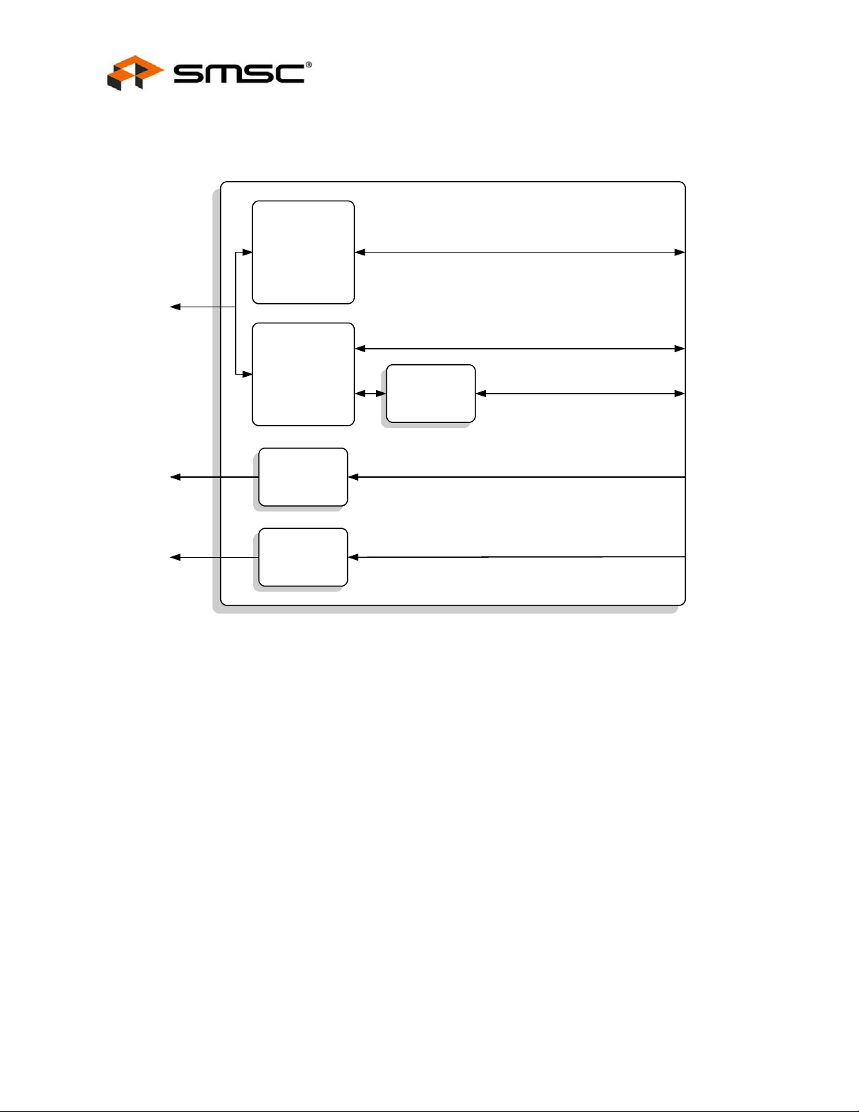
Single-Chip Ethernet Controller with HP Auto-MDIX Support and PCI Interface
3.2.1 PCI Bridge (PCIB) Block Diagram
PCI Bridge (PCIB)
Datasheet
PCI
nPME
nINT
PCI Master
PCI Target
PME Gating
Interrupt Gating
Figure 3.1 PCI Bridge Block Diagram
PCI
Configuration
Space CSR
To/From DMAC Arbiter
To/From CSR Blocks
PM Related Signals
(To/From PM)
PM Signal (From PM)
r
(
F
o
)
m
T
I
N
Q
I
R
Revision 1.22 (09-25-08) 24 SMSC LAN9420/LAN9420i
DATASHEET
Page 25
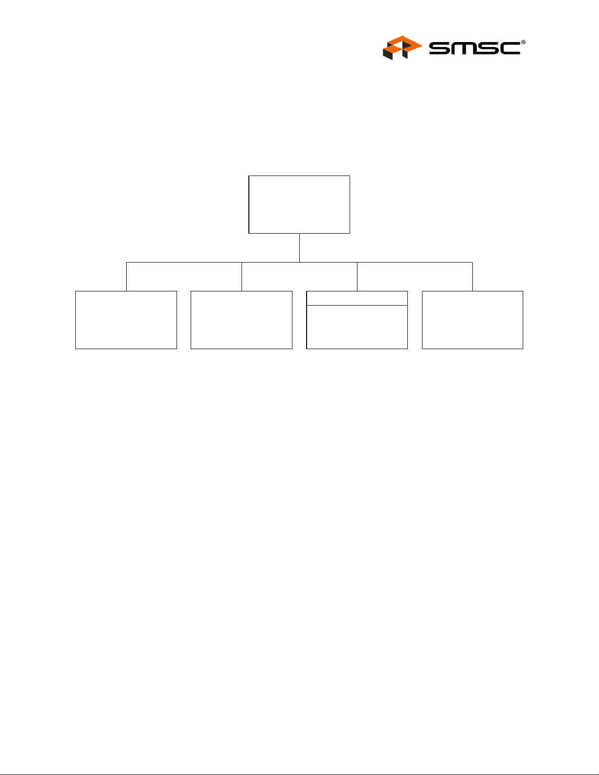
Single-Chip Ethernet Controller with HP Auto-MDIX Support and PCI Interface
Datasheet
3.2.2 PCI Interface Environments
The PCIB supports only Device operation. It functions as a simple bridge, permitting
LAN9420/LAN9420i to act as a master/target PCI device on the PCI bus. The Host performs PCI
arbitration and is responsible for initializing configuration space for all devices on the bus. Figure 3.2
illustrates Device operation.
Host
System
PCI
Bus
PCI
Component
PCI
Component
PCIB
LAN9420
PCI
Component
Figure 3.2 Device Operation
3.2.3 PCI Master Interface
The PCI Master Interface is used by the DMA engines to directly access the PCI Host’s memory. It is
used by the TX and RX DMA Controllers to access Host descriptor ring elements and Host DMA
buffers. No address translation occurs, as these entities are contained within the Host, which allocates
them within the flat PCI address space.
3.2.3.1 PCI Master Transaction Errors
In the event of an error during a descriptor read or during a tra nsmit data read, the DMA controller will
generate a Master Bus Error Interrupt (MBERR_INT).
When an MBERR_INT is asserted, all subsequent transactions from the DMAC will be aborted. In
order to cleanly recover from this condition, a software reset or H/W reset must be performed. A
software reset is accomplished by setting the SRST bit of the BUS_MODE register.
Note: It is guaranteed that the MBERR_INT will be reported on the frame upon which the error
occurred as follows:
- Errors on descriptor reads will be aborted immediately.
- Errors on TX data will be reported either upon the data or the close descrip tor (if the error
occurs on the last data transfer).
- DMA RX data and descriptor write operations are posted and will therefore not generate the
MBERR_INT.
SMSC LAN9420/LAN9420i 25 Revision 1.22 (09-25-08)
DATASHEET
Page 26

Single-Chip Ethernet Controller with HP Auto-MDIX Support and PCI Interface
3.2.4 PCI Target Interface
The PCI target interface implements the address spaces listed in Table 3.1.
Table 3.1 PCI Address Spaces
SPACE SIZE RESOURCE
Configuration 256 bytes PCI standard and PCIB-specific registers
BAR0...BAR2 RESERVED
BAR3 1 KB Control and Status Registers (Non-prefetchable area)
BAR4 256B Control and Status Registers (I/O area)
BAR5 RESERVED
Expansion ROM - RESERVED
The PCI Configuration space is used to identify PCI Devices, configure memory ranges, and manage
interrupts. The Host initializes and configures the PCI Device during a plug-and-play process.
Datasheet
The PCI Target Interface supports 32-bit slave accesses only. Non 32-bit PCI target reads to
LAN9420/LAN9420i will result in a full 32-bit read. Non 32-bit PCI target writes to LAN9420/L AN9420i
will be silently discarded.
3.2.4.1 PCI Configuration Space Registers
PCI Configuration Space Registers include the standard PCI header registers and PCIB extensions to
implement power management control/status registers. See Section 4.6, "PCI Configuration Space
CSR (CONFIG CSR)," on page 149 for further details. These registers exist in the co nfiguration space.
3.2.4.2 Control and Status Registers (CSR)
The PCI Target Interface all ows PCI bus masters to directly access the LAN9420/LAN9420i Control
and Status registers via memory or I/O operations. Each set of operations has an associated address
range that defines it as follows:
The non-prefetchable (NP) address range is mapped in BAR3. No data prefetch is performed when
serving PCI transactions targeting this address range.
The I/O address range is mapped in BAR4.
3.2.4.2.1 CSR ENDIA NNESS
The Non-Prefetchable address range contains a double mapping of the CSR. These mappings all ow
the registers to be accessed in little endian or big endian order. Figure 3.3, "CSR Double Endian
Mapping" illustrates the mapping. BA is the base address, as specified by BAR3.
Revision 1.22 (09-25-08) 26 SMSC LAN9420/LAN9420i
DATASHEET
Page 27
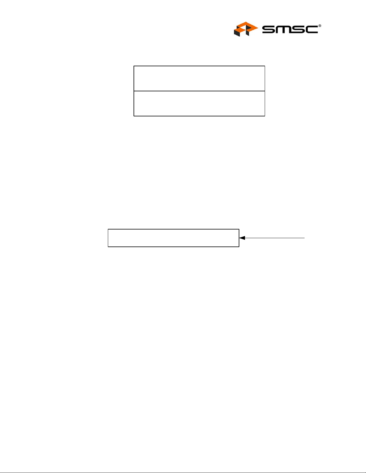
Single-Chip Ethernet Controller with HP Auto-MDIX Support and PCI Interface
Datasheet
.
BA + 3FCh
CSR - Big Endian (512 Bytes)
BA + 200h
BA + 1FCh
CSR - Little Endian (512 Bytes)
BA (BAR3)
Figure 3.3 CSR Double Endian Mapping
3.2.4.2.2 I/O MAPPING OF CSR
The I/O BAR (BAR4) is double mapped over the CSR space with the non-pre fetchable area. The CSR
big endian space is disabled, as the Host processors (Intel x86) that use the I/O BAR are little endian.
Note: A comparison of Figure 3.3 with Figure 3.4 indicates only the first 256 bytes of CSR little endian
space is addressable via the I/O BAR.
.
BA + 0FCh
CSR - Little Endian ( 256 Bytes)
BA (BAR4)
Figure 3.4 I/O Bar Mapping
3.2.4.3 PCI Target Interface Transaction Errors
If the Host system attempts an unsupported cycle type when accessing the CSR via the PCI Target
Interface, a slave transaction error will result and the PCI Target Interface will generate a Slave Bus
Error Interrupt (SBERR_INT), if enabled. CSR may only be read or written as DWORD quantities and
any other type of access is unsupported and will result in the assertion of SBERR_INT. Non-DWORD
reads will return a DWORD while non-DWORD writes are silently discarded. In order to cleanly recover
from this condition, a software reset or H/W reset must be performed. A so ftware reset is accomplished
by setting the SRST bit of the BUS_MODE register.
3.2.4.4 PCI Discard Timer
When the PCI master performs a read of LAN9420/LAN9420i, the PCI Bridge will fetch the data and
acknowledge the PCI transfer when data is available. If the PCI master malfunctions and does
complete the transaction within 32768 PCI clocks, LAN9420/LAN9420i wil l flush the data to prevent a
potential bus lock-up.
3.2.5 Interrupt Gating Logic
I/O BAR and nonprefetchable memory
are double mapped to
the CSR space
One set of interrupts exists: PCI Host interrupts (PCI interrupts from LAN9420/LAN9420i to the PCI
Host). PCI Host interrupts result from the assertion of the internal IRQ signal from the Interrupt
Controller. Refer to Section 3.3.1, "Interrupt Controller," on page 28 for sources of this interrupt.
Figure 3.5 illustrates how interrupts are sourced by the Interrupt Controller to the PCIB and are
propagated to the Host. The Interrupt is passed on to the Host only when the Host has e nabled it by
setting bit 10 in the PCI Device Command Register. The Host may obtain interrupt status by reading
SMSC LAN9420/LAN9420i 27 Revision 1.22 (09-25-08)
DATASHEET
Page 28
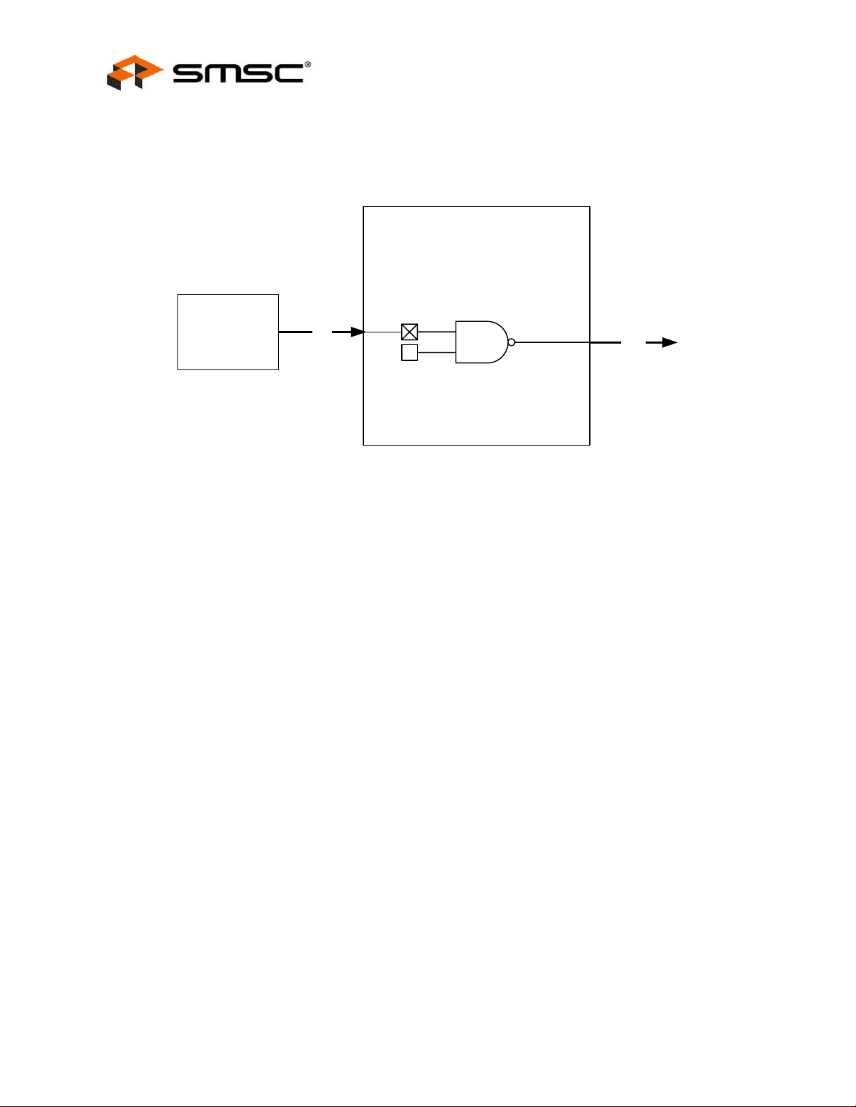
Single-Chip Ethernet Controller with HP Auto-MDIX Support and PCI Interface
Datasheet
Bit 3 of the PCI Device Status Register. The PCI Device Status Register and PCI Device Command
Register are standard registers in PCI Configuration Space. Please refer to Section 4.6, "PCI
Configuration Space CSR (CONFIG CSR)," on page 149 for details.
PCIB
Bit 3
PCI Device
Interrupt
Controller
IRQ
Status Register
RW
Bit 10
PCI Device
Command Register
nINT
(To Host)
Figure 3.5 Interrupt Generation
3.3 System Control Block (SCB)
The System Control Block includes an interrupt controller, wake detection logic, a general-purpose
timer, a free-run counter and system control and status registers.
Interrupt Controller: The interrupt controller can be programmed to interrupt the Host system
applications on the occurrence of various events. The interrupt is routed to the Host system via the
PCIB.
Wake Detection Logic: This logic detects the occurrence of an enabled wake event and asserts the
PCI nPME signal, if enabled.
General Purpose Timer (GPT): The general purpose timer can be configured to generate a system
interrupt upon timeout.
Free-Run Counter (FRC): A 32-bit free-running counter with a 160 ns resolution.
EEPROM Controller (EPC): An optional, external, Serial EEPROM may be used to store the default
values for the MAC address, PCI Subsystem ID, and PCI Subsystem Vendor ID. In addition, it may
also be used for general data storage. The EEPROM controller provides LAN9420/LAN9420i access
to the EEPROM and permits the Host to read, write and erase its contents.
System Control and Status Registers (SCSR): These registers control system functions that are not
specific to the DMAC, MAC or PHY.
3.3.1 Interrupt Controller
The Interrupt Controller handles the routing of all internal interrupt sources. Interrupts enter the
controller from various modules within LAN9420/LAN9420i. The Interrupt Controller drives the interrupt
request (IRQ) output to the PCI Bridge. The Interrupt Controller i s capable of generating PCI interrupts
on detection of the following internal events:
DMAC interrupt request (DMAC_INT)
PHY interrupt request (PHY_INT)
Revision 1.22 (09-25-08) 28 SMSC LAN9420/LAN9420i
DATASHEET
Page 29
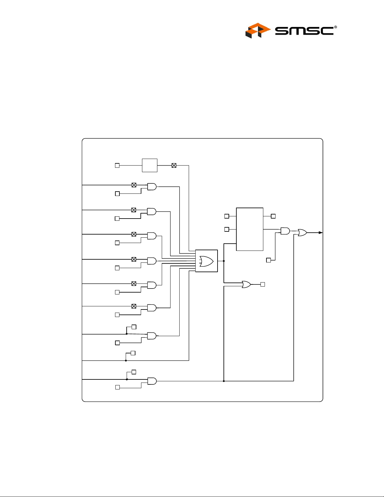
Single-Chip Ethernet Controller with HP Auto-MDIX Support and PCI Interface
Datasheet
General-purpose timer interrupt (GPT_INT)
General purpose Input/Output interrupt (GPIOx_INT)
Software interrupt (SW_INT)
Master bus error interrupt (MBERR_INT)
Slave bus error interrupt (SBERR_INT)
Wake event detection (WAKE_INT)
A Block diagram of the Interrupt Controller is shown in Figure 3.6
.
Interrupt Controller
SW_INT
(INT_STS Register)
0 to 1
DETECT
PHY_INT
RO
(INT_STS Register)
DMAC_INT
RO
(INT_STS Register)
WAKE_INT
RO
(INT_STS Register)
INT_DEAS[7:0]
(INT_CFG Register)
INT_DEAS_CLR
(INT_CFG Register)
Master Bus Error
Interrupt
Slave Bus Error
Interrupt
GPIO2 Interrupt
GPIO1 Interrupt
GPIO0 Interrupt
GP Timer Interrupt
PHY Interrupt
DMAC Interrupt
Wake Event Interrupt
SW_INT_EN
(INT_CTL Register)
MBERR_INT_EN
(INT_CTL Register)
SBERR_INT_EN
(INT_CTL Register)
GPIO2_INT_EN
(INT_CTL Register)
GPIO1_INT_EN
(INT_CTL Register)
GPIO0_INT_EN
(INT_CTL Register)
GPT_INT_EN
(INT_CTL Register)
PHY_INT_EN
(INT_CTL Register)
WAKE_INT_EN
(INT_CTL Register)
RW
MBERR_INT
(INT_STS Register)
RW
SBERR_INT
(INT_STS Register)
RW
GPIO2_INT
(INT_STS Register)
RW
GPIO1_INT
(INT_STS Register)
RW
GPIO0_INT
(INT_STS Register)
RW
GPT_INT
(INT_STS Register)
RW
RW
RW
RW RO
DEASSERTION
RW
TIMER
IRQ_EN
(INT_CTL Register)
IRQ_INT
(INT_CFG Register)
RW
RO
INT_DEAS_STS
(INT_CFG Register)
IRQ
(PCIB)
Figure 3.6 Interrupt Contr oller Block Diagram
The Interrupt Controller control and status register are contained within the System Control and Status
Registers (SCSR) block. The interrupt status register (INT_STS) reflects the current state of the
interrupt sources prior to qualification with their associated enables. The SW_INT, MBERR_INT,
SBERR_INT, GPIOx_INT, and GPT_INT are latched, and are cleared through the SCSR block upon a
SMSC LAN9420/LAN9420i 29 Revision 1.22 (09-25-08)
DATASHEET
Page 30

Single-Chip Ethernet Controller with HP Auto-MDIX Support and PCI Interface
Datasheet
write of '1' to the corresponding status bit in the INT_STS register. The remaining interrupts are cleared
from the source CSR.
The Interrupt Controller receives the wake event detection interrupt (WAKE_INT) from the wake
detection logic. If enabled, the wake detection logic is able to generate an interrupt to the PCI Bridge
on detection of a MAC wakeup event (Wakeup Frame or Magic Packet), or on an Ethernet link status
change (energy detect).
Note: LAN9420/LAN9 420i can optionally generate a PCI interrupt in addition to assertion of nPME
on detection of a power management event. Generation of a PCI interrupt is not the typical
usage.
Unlike the other interrupt sources, the software interrupt (SW_INT) is asserted on a 0-to-1 transition
of its enable bit (SW_INT_EN). The DMAC interrupt is enabled in the DMA controller. All other
Interrupts are enabled through the INT_EN register. Setting an enable bit high enables the
corresponding interrupt as a source of the IRQ.
The Interrupt Controller contains an interrupt de-assertion timer. This timer guarantees a minimum
interrupt de-assertion period for the IRQ. The de-assertion timer has a resolution of 10us and is
programmable through the INT_CFG SCSR (refer to Section 4.2.4, "Interrupt Configuration Register
(INT_CFG)," on page 91). A setting of all zeros disables the de-assertion timer. The state of the
interrupt de-assertion timer is reflected by the interrupt de-assertion timer status bit (INT_DEAS_STS)
bit in the IRQ_CFG register. When this bit is set, the de-assertion timer is currently in a de-assertion
interval, and, with the exception of the WAKE_INT, all pending interrupts are blocked.
Note: The interrupt de-assertion timer does not affect WAKE_INT. This interrupt event is able to
assert IRQ regardless of the state of the de-assertion timer.
The IRQ_INT status bit in the INT_CFG register reflects the aggregate status of all interrupt sources.
If this status bit is set, one or more enabled interrupts are active. The IRQ_INT status bit is not affected
by the de-assertion timer.
The IRQ output is enabled/disabled by the IRQ_EN enable bit in the INT_CT L register. When this bit
is cleared, with the exception of WAKE_INT, all interrupts to the PCI Bridge are disabled. When set,
interrupts to the PCI Bridge are enabled.
Note: The IRQ_EN does not affect WAKE_INT. This interrupt event is able to assert IRQ regardless
of the state of IRQ_EN.
3.3.2 Wake Event Detection Logic
LAN9420/LAN9420i supports the ability to generate wake interrupts on detection of a Magic Packet,
Wakeup Frame or Ethernet link status change (energy detect). When enabled to do so, the wake event
detection logic generates an interrupt to the Interrupt Controller. Refer to Section 3.7.6, "Detecting
Power Management Events," on page 80 for more info rmation on the wake event interrupt.
Wakeup frame detection must be enabled in the MAC before detection can occur. Likewise, the energy
detect interrupt must be enabled in the PHY before this interrupt can be used.
3.3.3 General Purpose Timer (GPT)
The General Purpose Timer is a programmable device that can be used to generate periodic system
interrupts. The resolution of this timer is 100uS.
The GP Timer loads the GPT_CNT Register with the value in the GPT_LOAD field and begins counting
when the TIMER_EN bit is asserted (1). On a chip-level reset, or when the TIMER_EN bit changes
from asserted (1) to de-asserted (0), the GPT_LOAD field is initialized to FFFFh. The GPT_CNT
register is also initialized to FFFFh on a reset. Software can write the pre-load value into the
GPT_LOAD field at any time (e.g., before or after the TIMER_EN bit is asserted). The GPT Enable bit
TIMER_EN is located in the GPT_CFG register.
Revision 1.22 (09-25-08) 30 SMSC LAN9420/LAN9420i
DATASHEET
Page 31

Single-Chip Ethernet Controller with HP Auto-MDIX Support and PCI Interface
Datasheet
Once enabled, the GPT counts down either until it reaches 0000h, or until a new pre-load value is
written to the GPT_LOAD field. At 0000h, the counter wraps around to FFFFh, asserts the GPT
interrupt status bit (GPT_INT) and the GPT interrupt (if the GPT_INT_EN bit is set), and continues
counting. GPT_INT is a sticky bit (R/WC), Once the GPT_INT bit is asserted, it can only be cleared
by writing a '1' to the bit. The GPT_INT hardware interrupt can only be asserted if the GPT_INT_EN
bit is set.
3.3.4 Free-Run Counter (FRC)
The FRC is a simple 32-bit up counter. The FRC counts at fixed rate of 6.25MHz (160nS resolution).
When the FRC reaches a value of FFFF_FFFFh, it wraps around to 0000_0000h and continues
counting. The FRC is operational in all power states. The FRC has no fixed function in
LAN9420/LAN9420i and is ideal for use by drivers as a timebase. The current FRC count is rea dable
in FREE_RUN SCSR. Please refer to Section 4.2.10, "Free Run Counter (FREE_RUN)," on page 98
for more information on this register.
3.3.5 EEPROM Controller (EPC)
LAN9420/LAN9420i may use an optional, external, EEPROM to store the default values for the MAC
address, PCI Subsystem ID, and PCI Subsystem Vendor ID. The PCI Subsystem ID and PCI
Subsystem Vendor ID are used by the PCI Bridge (PCIB). The MAC address is used as the default
Ethernet MAC address and is loaded into the MAC’s ADDRH and ADDRL registers. If a properly
configured EEPROM is not detected, it is the responsibility of the Host LAN Driver to set the IEEE
addresses.
After a system-level reset occurs, LAN9420/LAN9420i will load the default values from a properly
configured EEPROM. LAN9420/LAN9420i will not accept PCI target transactions unti l this process is
completed.
The LAN9420/LAN9420i EEPROM controller also allows the Host system to read, write and erase the
contents of the Serial EEPROM. The EEPROM controller supports most “93C46” type EEPROMs
configured for 128 x 8-bit operation.
3.3.5.1 EEPROM Format
Table 3.2 illustrates the format in which data is stored inside of the EEPROM.
EEPROM BYTE ADDRESS EEPROM CONTENTS
0 0xA5
1 MAC Address [7:0]
2 MAC Address [15:8]
3 MAC Address [23:16]
4 MAC Address [32:24]
5 MAC Address [39:33]
Table 3.2 EEPROM Format
6 MAC Address [47:40]
7 Subsystem Device ID [7:0]
8 Subsystem Device ID [15:8]
9 Subsystem Vendor ID [7:0]
0Ah Subsystem Vendor ID [15:8]
SMSC LAN9420/LAN9420i 31 Revision 1.22 (09-25-08)
DATASHEET
Page 32

Single-Chip Ethernet Controller with HP Auto-MDIX Support and PCI Interface
Note: EEPROM byte addresses past 0Ah can be used to store data for any purpose.
The signature value of 0xA5 is stored at address 0. A different signature value indicates to the
EEPROM controller that no EEPROM or an un-programmed EEPROM is attached to
LAN9420/LAN9420i. In this case, following default values are used for the Subsystem Device ID
(SSID), Subsystem Vendor ID (SSVID), and the MAC address.
Table 3.3 EEPROM Variable Defaults
VARIABLE DEFAULT
Subsystem ID [15:0] 0x9420
Subsystem Vendor ID [15:0] 0x1055
MAC Address [47:0] 0xFFFF_FFFF_FFFF
3.3.5.2 MAC Address, Subsystem ID, and Subsystem Vendor ID Auto-Load
On a system-level reset, the EEPROM controller attempts to read the first byte of data from the
EEPROM (address 00h). If the value A5h is read from the first address, then the EEPROM controller
will assume that an external EEPROM is present. The EEPROM controller will then access the next
EEPROM byte and send it to the MAC Address register byte 0 (ADDRL[7:0]). This process will be
repeated for the next five bytes of the MAC Address, thus fully programming the 48-bit MAC address.
The Subsystem ID and Subsystem Vendor ID are similarly extracted from the EEPROM and are used
to set the value of the analogous PCI Header registers contained within the PCIB. Once all eleven
bytes have been programmed, the “EEPROM Loaded” bit is set in the E2P_CMD register. A detailed
explanation of the EEPROM byte ordering with respect to the MAC address is given in Section 4.4.3,
"MAC Address Low Register (ADDRL)," on page 124 .
Datasheet
If an 0xA5h is not read from the first address, the EEPROM controll er will end in itialization. Th e default
values, as specified in Table 3.3, will then be assumed by the associated registers. It is then the
responsibility of the Host LAN driver software to set the IEEE address b y writing to the MAC’s ADDRH
and ADDRL registers.
3.3.5.3 EEPROM Host Operations
After the EEPROM controller has finished reading (or attempting to read) the EEPROM after a systemlevel reset, the Host is free to perform other EEPROM operations. EEPROM operations are performed
using the EEPROM Command (E2P_CMD) and EEPROM Data (E2P_DATA) registers. Section 4.2.11,
"EEPROM Command Register (E2P_CMD)," on page 99 provides an explanation of the supported
EEPROM operations.
If the EEPROM operation is the “write location” (WRITE) o r “write all” (WRAL) commands, the Host
must first write the desired data into the E2P_DATA register. The Host must then issue the WRITE or
WRAL command using the E2P_CMD register by setting the EPC_CMD field appropriately. If the
operation is a WRITE, the EPC_ADDR field in E2P_CMD must also be set to the desired locatio n. The
command is executed when the Host sets the EPC_BSY bit high. The completion of the operation is
indicated when the EPC_BSY bit is cleared.
If the EEPROM operation is the “read location” (READ) operation, the Host must issue the READ
command using the E2P_CMD register with the EPC_ADDR set to the desired location. The command
is executed when the Host sets the EPC_BSY bit high. The completion of the operation is indi cated
when the EPC_BSY bit is cleared, at which time the data from the EEPROM may be read from the
E2P_DATA register.
Other EEPROM operations are performed by writing the appropriate command to the E2P_CMD
register. The command is executed when the Host sets the EPC_BSY bit high. The completion of the
operation is indicated when the EPC_BSY bit is cleared. In all cases, the Host must wait for EPC_BSY
to clear before modifying the E2P_CMD register.
Revision 1.22 (09-25-08) 32 SMSC LAN9420/LAN9420i
DATASHEET
Page 33

Single-Chip Ethernet Controller with HP Auto-MDIX Support and PCI Interface
Datasheet
Note: The EEPROM device powers-up in the erase/write disabled state. To modify the contents of
the EEPROM, the Host must first issue the EWEN command.
If an operation is attempted, and an EEPROM device does not respond within 30mS,
LAN9420/LAN9420i will timeout, and the EPC Time-out bit (EPC_TO) in the E2P_CMD register will be
set.
Figure 3.7 illustrates the Host accesses required to perform an EEPROM Read or Write operation.
EEPROM Write EEPROM Read
Busy Bit = 0
Idle
Write Data
Register
Write
Command
Register
Read
Command
Register
Idle
Write
Command
Register
Read
Command
Register
Busy Bit = 0
Read Data
Register
Figure 3.7 EEPROM Access Flow Diagram
The Host can disable the EEPROM interface through the GPIO_CFG register. When the interface is
disabled, the EEDIO and ECLK signals can be used as general-purpose outputs, or they may be u sed
to monitor internal MII signals.
3.3.5.3.1 SUPPORTED EEPROM OPERATIONS
The EEPROM controller supports the following EEPROM operations under Host control via the
E2P_CMD register. The operations are commonly supported by “93C46” EEPROM devices. A
description and functional timing diagram is provided below for each operation. Please refer to the
E2P_CMD register description in Section 4.2.11, "EEPROM Command Register (E2P_CMD)," on
page 99 for E2P_CMD field settings for each command.
ERASE (Erase Location): If erase/write operations are enabled in the EEPROM, this command will
erase the location selected by the EPC Address field (EPC_ADDR). The EPC_TO bit is set if the
EEPROM does not respond within 30ms.
SMSC LAN9420/LAN9420i 33 Revision 1.22 (09-25-08)
DATASHEET
Page 34

EECS
EECLK
Single-Chip Ethernet Controller with HP Auto-MDIX Support and PCI Interface
Datasheet
t
CSL
EEDIO (OUTPUT)
EEDIO (INPUT)
ERAL (Erase All): If erase/write operations are enabled in the EEPROM, this command wil l initiate a
bulk erase of the entire EEPROM.The EPC_TO bit is set if the EEPROM does not respond within
30ms.
EECS
EECLK
EEDIO (OUTPUT)
11A6 A0
1
Figure 3.8 EEPROM ERASE Cycle
1010
0
t
CSL
EEDIO (INPUT)
Figure 3.9 EEPROM ERAL Cycle
Revision 1.22 (09-25-08) 34 SMSC LAN9420/LAN9420i
DATASHEET
Page 35

Single-Chip Ethernet Controller with HP Auto-MDIX Support and PCI Interface
Datasheet
EWDS (Erase/Write Disable): After issued, the EEPROM will ignore erase and write commands. To
re-enable erase/write operations issue the EWEN command.
EECS
EECLK
t
CSL
EEDIO (OUTPUT)
1000
0
EEDIO (INPUT)
Figure 3.10 EEPROM EWDS Cycle
EWEN (Erase/Write Enable): Enables the EEPROM for erase and write operations. The EEPROM
will allow erase and write operations until the “Erase/Write Disable” command is sent, or until power
is cycled.
Note: The EEPROM device will power-up in the erase/write-disabled state. Any erase or write
operations will fail until an Erase/Write Enable command is issued.
t
CSL
EECS
EECLK
EEDIO (OUTPUT)
1011
0
EEDIO (INPUT)
Figure 3.11 EEPROM EWEN Cycle
SMSC LAN9420/LAN9420i 35 Revision 1.22 (09-25-08)
DATASHEET
Page 36

Single-Chip Ethernet Controller with HP Auto-MDIX Support and PCI Interface
Datasheet
READ (Read Location): This command will cause a read of the EEPROM location pointed to by EPC
Address (EPC_ADDR). The result of the read is available in the E2P_DATA register.
t
CSL
EECS
EECLK
EEDIO (OUTPUT)
EEDIO (INPUT)
EECS
EECLK
EEDIO (OUTPUT)
110A6
A0
D7 D0
Figure 3.12 EEPROM READ Cycle
WRITE (Write Location): If erase/write operations are enabled in the EEPROM, this command will
cause the contents of the E2P_DATA register to be written to the EEPROM location selected by the
EPC Address field (EPC_ADDR). The EPC_TO bit is set if the EEPROM does not respond within
30ms.
t
CSL
0
11A6 A0 D7 D0
EEDIO (INPUT)
Figure 3.13 EEPROM WRITE Cycle
Revision 1.22 (09-25-08) 36 SMSC LAN9420/LAN9420i
DATASHEET
Page 37

Single-Chip Ethernet Controller with HP Auto-MDIX Support and PCI Interface
Datasheet
WRAL (Write All): If erase/write operations are enabled in the EEPROM, this command will cause the
contents of the E2P_DATA register to be written to every EEPROM memory location. The EPC_TO bit
is set if the EEPROM does not respond within 30ms.
EECS
EECLK
t
CSL
EEDIO (OUTPUT)
EEDIO (INPUT)
0
1
0 01
D7 D0
Figure 3.14 EEPROM WRAL Cycle
Table 3.4, "Required EECLK Cycles", shown below, shows the number of EECLK cycles required for
each EEPROM operation.
T able 3.4 Required EECLK Cycles
OPERATION REQUIRED EECLK CYCLES
ERASE 10
ERAL 10
EWDS 10
EWEN 10
READ 18
WRITE 18
WRAL 18
3.3.5.3.2 HOST INITIATED MAC ADDRESS, SSID, SSVID RELOAD
The Host can initiate a reload of the MAC address, SSID, and SSVID from the EEPROM by issuing
the RELOAD command via the E2P command (E2P_CMD) register. If the first byte read from the
EEPROM is not A5h, it is assumed that the EEPROM is not present, or not programmed, and the
RELOAD operation will fail. The “EEPROM Loaded” bit indicates a successful reload of the MAC
address, SSID, and SSVID.
3.3.5.3.3 EEPROM COMMAND AND DATA REGISTERS
Refer to Section 4.2.11, "EEPROM Command Register (E2P_CMD)," on page 99 and Section 4.2.12,
"EEPROM Data Register (E2P_DATA)," on page 102 for a detailed description of these registers.
Supported EEPROM operations are described in these sections.
3.3.5.3.4 EEPROM TIMING
Refer to Section 5.8, "EEPROM Timing," on page 165 for detailed EEPROM timing specifications.
SMSC LAN9420/LAN9420i 37 Revision 1.22 (09-25-08)
DATASHEET
Page 38

Single-Chip Ethernet Controller with HP Auto-MDIX Support and PCI Interface
3.3.6 System Control and Status Registers (SCSR)
Please refer to Section 4.2, "System Control and Status Registers (SCSR)," on page 86 for a complete
description of the SCSR.
3.4 DMA Controller (DMAC)
The DMA Controller is designed to transfer data from and to the MAC RX and TX Data paths. Similar
to the MAC, it contains separate TX and RX data paths that are controlled by a single arbiter.
The DMA Controller includes the following features:
Generic 32-bit DMA with single-channel Transmit and Receive engines
Optimized for packet-oriented DMA transfers with frame delimiters
Supports dual-buffer and linked-list Descriptor Chaining
Descriptor architecture allows large blocks of data transfer with minimum Host intervention - each
descriptor can transfer up to 2KB of data
Comprehensive status reporting for normal operation and transfers with errors
Supports programmable interrupt options for different operational conditio ns
Supports Start/Stop modes of operation
Selectable round-robin or fixed priority arbitration between Rece ive and Transmit engines
Datasheet
The DMA controller consists of independent transmit (TX) and receive (RX) engines and a control and
status register space (DCSR). The transmit engine transfers data from Host memory through the PCI
Bridge (PCIB) to the MAC, while the receive engin e transfers data from the MAC, through the PCIB
to Host memory. The DMAC utilizes descriptors to efficiently move data from source to destination with
minimal Host intervention. Descriptors are 4-DWORD (16-byte) aligned data structures in Host memory
that inform the DMAC of the location of data buffers in Host memory and also provide a mechanism
for communicating status to the Host on completion of DMA transactions. The DMAC has been
designed for packet-oriented data transfer, such as frames in Ethernet. The DMAC can be programmed
to assert an interrupt for situations such as frame transmit or receive transfer completed, and other
normal, as well as error conditions that are described in the DMAC Control and Status Registers
(DCSR) section.
Note: Descripto rs should not cross cache line boundaries if cache memory is used.
3.4.1 DMA Controller Architecture
The DMA Controller has four main hardware components: TX DMA engine, RX DMA engine, the DMA
arbiter, and the DCSR.
TX DMA Engine - The transmit DMA engine fetches transmit descriptors from Host memory and
handles data transfers from Host memory to the MAC destination port.
RX DMA Engine - The receive DMA engine fetches receive descriptors from Host memory an d
handles data transfers from the MAC source port to destination bu ffers in Host memory.
DMA Arbiter - The DMA arbiter controls access to Host memory. It can be configured to support
round robin or fixed priority arbitration.
DCSR - The DMA control and status register block implements register bits that control and monitor
the operation of the DMA subsystem.
3.4.2 Data Descriptors and Buffers
The DMAC and the driver communicate through two data structures:
DMA Control and Status Registers (DCSR), as described in Section 4.3, "DMAC Control and Status
Registers (DCSR)," on page 103.
Revision 1.22 (09-25-08) 38 SMSC LAN9420/LAN9420i
DATASHEET
Page 39

Single-Chip Ethernet Controller with HP Auto-MDIX Support and PCI Interface
Datasheet
Descriptor lists and data buffers, described in this chapter.
The DMAC transfers RX data frames to the RX buffers in Host memory and transmits data from TX
buffers in the Host memory. Descriptors that reside in Host memory contain pointers to these buffers.
There are two DMA descriptor lists; one for receive operations and one for transmi t operations. The
base address of each list is written into the RX_BASE_ADDR and TX_BASE_ADDR registers,
respectively. A descriptor list is forward linked (either implicitly or explicitly). Descriptors are usually
placed in the physical memory in an incrementing and a contiguou s addressing scheme. However, the
last descriptor may point back to the first entry to create a ring structure. Explicit chaining of descriptors
is accomplished by setting the Second Address Chained flag in both re ceive and transmit descriptors
(RCH - RDES1[24] and TCH - TDES1[24]). Each descriptor's list resides in Host memory. Each
descriptor can point to a maximum of two buffers. This enables the use of two physically addressed,
as well as non-contiguous memory buffers.
Data buffers reside in the Host memory space. An Ethernet frame can be fragmented across multiple
data buffers, but a data buffer cannot contain more than one Ethernet frame. Data chaining refers to
Ethernet frames that span multiple data buffers. Data buffers contain only data used in the Ethernet
frame. The buffer status is maintained in the descriptor. In a ring structure, each descriptor can point
to up to two data buffers with the restriction that both buffers contain data for the same Ethernet frame.
In a chain structure, each descriptor points to a single data buffer and to the next descriptor in the
chain.
The DMAC will skip to the next frame buffer when end of frame is detected. Data chaining can be
enabled or disabled. The ring and chain type descriptor structures are illustrated in Figure 3.15.
Note: Descripto rs of zero buffer length are not supported at the initial and final descriptors of a chain.
SMSC LAN9420/LAN9420i 39 Revision 1.22 (09-25-08)
DATASHEET
Page 40

Ring Structure:
DESCRIPTOR 0
DESCRIPTOR 1
DESCRIPTOR n
Chain Structure:
Single-Chip Ethernet Controller with HP Auto-MDIX Support and PCI Interface
Datasheet
BUFFER 1
BUFFER 2
BUFFER 1
BUFFER 2
BUFFER 1
BUFFER 2
BUFFER 1
DESCRIPTOR 0
BUFFER 1
DESCRIPTOR 1
NEXT DESCRIPTOR
Figure 3.15 Ring and Chain Descr iptor Structures
Revision 1.22 (09-25-08) 40 SMSC LAN9420/LAN9420i
DATASHEET
Page 41

Single-Chip Ethernet Controller with HP Auto-MDIX Support and PCI Interface
Datasheet
3.4.2.1 Receive Descriptors
The receive descriptors must be 4-DWORD (16-byte) aligned. Except for the case where descriptor
address chaining is disabled (RCH=0), there are no alignment restricti ons on receive buffer addresses.
Providing two buffers, two byte-count buffers, and two addre ss pointers in each descriptor facilitates
compatibility with various types of memory-management schemes. Figure3.16 shows the receive
descriptor.
OW FL
RDES0
FF ES DE LE RF MF FS LS TL CS FT RW ME DB CE R
31 30 29 28 27 26 25 24 23 22 21 20 19 18 17 16 15 14 13 12 11 10 9 8 7 6 5 4 3 2 1 0
R
RDES1
RDES2
RDES3
RESERVED
31 30 29 28 27 26 25 24 23 22 21 20 19 18 17 16 15 14 13 12 11 10 9 8 7 6 5 4 3 2 1 0
31 30 29 28 27 26 25 24 23 22 21 20 19 18 17 16 15 14 13 12 11 10 9 8 7 6 5 4 3 2 1 0
31 30 29 28 27 26 25 24 23 22 21 20 19 18 17 16 15 14 13 12 11 10 9 8 7 6 5 4 3 2 1 0
RE RC RES RBS2 RBS1
BUFFER 1 ADDRESS POINTER
BUFFER 2 ADDRESS POINTER
Figure 3.16 Receive Descripto r
Receive Descriptor 0 (RDES0)
RDES0 contains the received frame status, the frame length, and the descriptor ownership information.
Table 3.5 RDES0 Bit Fields
BITS DESCRIPTION
31 OWN - Own Bit
When set, indicates that the descriptor block and associated buffer(s) are owned by th e DMA
controller. When reset, indicates that the descriptor block and associated buffer(s) are owned by
the Host system.
Host Actions: Checks this bit to determine ownership of the descriptor block and associated
buffer(s). The Host sets this bit to pass ownership to the DMAC. The Host does not modify a
descriptor block or access its associated buffer(s) until this bit is cleared by DMAC or until the
DMAC is in STOPPED state, whichever comes first.
DMAC Actions: Reads this bit to determine ownership of the descriptor block and its associated
buffer(s). The DMAC clears this bit either when it completes the frame reception or wh en the
buffers that are associated with this descriptor are full. By clearing this bit, the DMAC clo ses the
descriptor block and passes ownership to the Host. If the DMAC fetches a descriptor with the
OWN bit cleared, the DMAC state machine enters the SUSPENDED state.
30 FF - Filter Fail
Indicates that the current frame failed the receive address filtering. Th is bit can only be set when
receive all (RXALL) is set in the MAC control regi ster (MAC_CR). This bit is only valid when the
last descriptor (LS) bit is set and the received frame is g reater than or equal to 64 bytes in leng th.
Host Actions: Checks this bit to determine status.
DMAC Actions: Sets/clears this bit to define status.
SMSC LAN9420/LAN9420i 41 Revision 1.22 (09-25-08)
DATASHEET
Page 42

Single-Chip Ethernet Controller with HP Auto-MDIX Support and PCI Interface
Table 3.5 RDES0 Bit Fields (continued)
BITS DESCRIPTION
Datasheet
29:16 FL - Frame Length
15 ES - Error Summary
14 DE - Descriptor Error
13 RESERVED
Indicates the length in bytes, including the CRC, of the received frame that was transferred to
Host memory. This field is set only after the last descriptor (LS) bit is set and the descriptor error
(DE) is reset.
Host Actions: Reads this field to determine Frame Length .
DMAC Actions: Initializes this field to define Frame Length.
Indicates the logical OR of the following RDES0 bits:
RDES0[1] - CRC error
RDES0[6] - Collision seen
RDES0[7] - Frame too long
RDES0[11] - Runt frame
RDES0[14] - Descriptor Error
Host Actions: Checks this bit to determine status.
DMAC Actions: Sets/clears this bit to define status.
When set, indicates a frame truncation caused by a frame that does not fit within the current
descriptor buffers, and that the DMA controller does not own the next descriptor. The frame is
truncated. This field is set only after the last descriptor (LS) bit is set.
Host Actions: Checks this bit to determine status.
DMAC Actions: Sets/clears this bit to define status.
Host Actions: Cleared on writes and ignored on reads.
DMAC Actions: Ignored on reads and cleared on write s.
12 LE - Length Error
11 RF - Runt Frame
10 MF - Multicast Frame
9 FS - First Descriptor
8 LS - Last Descriptor
When set, this bit indicates that the actual length does not match with the Length/Type field of
the incoming frame.
Host Actions: Checks this bit to determine status.
DMAC Actions: Sets/clears this bit to define status.
When set, this bit indicates that frame was prematurely terminated before the col lision window
(64 bytes). Runt frames are passed on to the Host memory only if the Pass Bad Frames bit
(PASS_BAD) in the MAC control register (MAC_CR) is set.
Host Actions: Checks this bit to determine status.
DMAC Actions: Sets/clears this bit to define status.
When set, this bit indicates that the received frame has a Multicast addre ss.
Host Actions: Checks this bit to determine status.
DMAC Actions: Sets/clears this bit to define status.
When set, indicates that this descriptor contains the first buffer of a frame. If the size of the first
buffer is 0, the second buffer contains the beginning of the frame. If the size of the second buffer
is also 0, the second descriptor contains the beginning of the frame.
Host Actions: Checks this bit to determine status.
DMAC Actions: Sets/clears this bit to define status.
When set, indicates that the buffers pointed to by this descriptor are the last buffers of the frame.
Host Actions: Checks this bit to determine status.
DMAC Actions: Sets/clears this bit to define status.
Revision 1.22 (09-25-08) 42 SMSC LAN9420/LAN9420i
DATASHEET
Page 43

Single-Chip Ethernet Controller with HP Auto-MDIX Support and PCI Interface
Datasheet
Table 3.5 RDES0 Bit Fields (continued)
BITS DESCRIPTION
7 TL - Frame To o Long
When set, indicates the frame length exceeds maximum Ethernet-specified si ze of 1518 bytes
(or 1522 bytes when VLAN tagging is enabled). This bit is valid only when last descri ptor (LS) is
set. Frame too long is only a frame length indication and does not cau se any frame truncation.
Host Actions: Checks this bit to determine status.
DMAC Actions: Sets/clears this bit to define status.
6 CS - Collision Seen
When set, this bit indicates that the frame has seen a collision after the collision window. This
indicates that a late collision has occurred.
Host Actions: Checks this bit to determine status.
DMAC Actions: Sets/clears this bit to define status.
5 FT - Frame Type
When set, indicates that the frame is an Ethernet-type frame (frame length field is greater than
or equal to 1536 bytes). When clear, indicates that the frame is an IEEE 802.3 frame. This bit is
not valid for runt frames of less than 14 bytes.
Host Actions: Checks this bit to determine status.
DMAC Actions: Sets/clears this bit to define status.
4 RW – Receive Watchdog
When set, indicates that the receive watchdog timer expired while receivin g the current packet
with length greater than 2048 bytes through 2560 bytes.
Host Actions: Checks this bit to determine status.
DMAC Actions: Sets/clears this bit to define status.
3 ME - MII Error
When set, this bit indicates that a receive error was detected duri ng frame reception (RX_ER
asserted on internal MII bus).
Host Actions: Checks this bit to determine status.
DMAC Actions: Sets/clears this bit to define status.
2 DB - Dribbling Bit
When set, indicates that the frame contained a noninteger mul tiple of 8 bits. This error is reported
only if the number of dribbling bits in the last byte is 4 in MII operating mode, or at least 3 in 10
Mb/s serial operating mode. This bit is not valid if collision seen (CS - RDES0[6]) is set. If set,
and the CRC error (CE - RDES0[1]) is reset, then the packet is valid.
Host Actions: Checks this bit to determine status.
DMAC Actions: Sets/clears this bit to define status.
1 CE - CRC Error
When set, indicates that a cyclic redundancy check (CRC) error occurred on the received frame.
This bit is also set when the MII error signal is asserted during the reception of a receive packet
even though the CRC may be correct. This bit is not valid if one of the following conditions exist:
The received frame is a runt frame
A collision occurred whi le the packet was being received
A watchdog timeout occurred while the packet was being received
Host Actions: Checks this bit to determine status.
DMAC Actions: Sets/clears this bit to define status.
0 RESERVED
Host Actions: Cleared on writes and ignored on reads.
DMAC Actions: Ignored on reads and cleared on write s.
SMSC LAN9420/LAN9420i 43 Revision 1.22 (09-25-08)
DATASHEET
Page 44

Single-Chip Ethernet Controller with HP Auto-MDIX Support and PCI Interface
Receive Descriptor 1 (RDES1)
Table 3.6 RDES1 Bit Fields
BITS DESCRIPTION
31:26 RESERVED
Host Actions: Cleared on writes and ignored on reads.
DMAC Actions: Ignored on reads. DMAC does not write to RDES1.
Datasheet
25 RER - Receive End of Ring
24 RCH - Second Address Chained
23:22 RESERVED
21:11 RBS2 - Receive Buffer 2 Size
10:0 RBS1 - Receive Buffer 1 Size
When set, indicates that the DMAC reached the final descriptor. Upon servicing this descriptor,
the DMAC returns to the base address of the DMA descriptor list pointed to by the Receive List
Base Address Register (RX_BASE_ADDR).
Host Actions: Initializes this bit.
DMAC Actions: Reads this bit to determine if this is the final descriptor in the ring.
When set, indicates that the second address in the descriptor is the ne xt descriptor address,
rather than the second buffer address. When RCH is set, RBS2 (RDES1[21:11]) must be all
zeros. RCH is ignored if RER (RDES1[25]) is set.
Host Actions: Initializes this bit.
DMAC Actions: Reads this bit to determine if second address is next descriptor address.
Host Actions: Cleared on writes and ignored on reads.
DMAC Actions: Ignored on reads. DMAC does not write to RDES1.
Indicates the size, in bytes, of the second data buffer. The buffer size must be a multiple of 4.
This field is not valid if RCH (RDES1[24]) is set.
Host Actions: Initializes this field.
DMAC Actions: Reads this field to determine the allocated size of associated data buffer.
Indicates the size, in bytes, of the first data buffer. The buffer size must be a multiple of 4. In the
case the buffer size is not a multiple of 4, the resulting behavior is undefined. If th is field is 0,
the DMA controller ignores this buffer and uses buffer2. (This field cannot be zero if the
descriptor chaining is used – Second Address Chained (RCH - R DES1[24]) is set).
Host Actions: Initializes this field.
DMAC Actions: Reads this field to determine the allocated size of associated data buffer.
Receive Descriptor 2 (RDES2)
Table 3.7 RDES2 Bit Fields
BITS DESCRIPTION
31:0 Buffer 1 Address Pointer
Revision 1.22 (09-25-08) 44 SMSC LAN9420/LAN9420i
Indicates the address of buffer 1 in the Host memory. There are no limitations on the buffer
address alignment.
Host Actions: Initializes this field.
DMAC Actions: Reads this field upon opening a new DMA descriptor to obtain the buffer
address.
DATASHEET
Page 45

Single-Chip Ethernet Controller with HP Auto-MDIX Support and PCI Interface
Datasheet
Receive Descriptor 3 (RDES3)
Table 3.8 RDES3 Bit Fields
BITS DESCRIPTION
31:0 Buffer 2 Address Pointer (Next Descr iptor Address)
The RCH (Second Address Chained) bit (RDES1[24]) determines the usage of this field as
follows:
RCH is zero: This field contains the pointer to the address of buffer 2 in Host memory. The buffer
must be DWORD (32-bit) aligned (RDES3[1:0] = 00b). In the case where the buffer is not
DWORD aligned, the resulting behavior is undefined.
RCH is one: Descriptor chaining is in use and this field contains the pointer to the next descriptor
in Host memory. The descriptor must be 4-DWORD (16-byte) aligned (RDES3[3:0] = 0000b). In
the case where the buffer is not 4-DWORD aligned, the resulting behavior is undefined .
Note: If RER (RDES1[25]) is set, RCH is ignored and this field is treated as a pointer to buffer
2 as in the “RCH is zero” case above.
Host Actions: Initializes this field.
DMAC Actions: Reads this field upon opening a new DMA descriptor to obtain the buffer
address.
3.4.2.2 Transmit descriptors
The descriptors must be 4-DWORD (16-byte) aligned, while there are no alignment restrictions on
transmit buffer addresses. Providing two buffers, two byte-count buffers, and two address pointers in
each descriptor facilitates compatibility with various types of memory-management schemes.
Figure 3.17 shows the Transmit Descriptor format.
TDES0
TDES1
TDES2
TDES3
OW
31 30 29 28 27 26 25 24 23 22 21 20 19 18 17 16 15 14 13 12 11 10 9 8 7 6 5 4 3 2 1 0
IC LS FS R AC TE TC DP R TBS2 TBS1CK
31 30 29 28 27 26 25 24 23 22 21 20 19 18 17 16 15 14 13 12 11 10 9 8 7 6 5 4 3 2 1 0
31 30 29 28 27 26 25 24 23 22 21 20 19 18 17 16 15 14 13 12 11 10 9 8 7 6 5 4 3 2 1 0
31 30 29 28 27 26 25 24 23 22 21 20 19 18 17 16 15 14 13 12 11 10 9 8 7 6 5 4 3 2 1 0
RESERVED ES RES LC NC LT EC HF CC ED UE DE
BUFFER 1 ADDRESS POINTER
BUFFER 2 ADDRESS POINTER
Figure 3.17 Transmit Descriptor
SMSC LAN9420/LAN9420i 45 Revision 1.22 (09-25-08)
DATASHEET
Page 46

Single-Chip Ethernet Controller with HP Auto-MDIX Support and PCI Interface
Transmit Descriptor 0 (TDES0)
TDES0 contains the transmitted frame status and the descriptor ownership information.
Table 3.9 TDES0 Bit Fields
BITS DESCRIPTION
Datasheet
31 OWN - Own Bit
30:16 RESERVED
15 ES - Err or Summary
When set, indicates that the descriptor block and associated buffer(s) are owned by the DMA
controller. When reset, indicates that the descriptor block and associated buffer(s) are owned by
the Host system.
Host Actions: Checks this bit to determine ownership of the descriptor block and associated
buffer(s). The Host sets this bit to pass ownership to the DMAC. The Host does not modify a
descriptor block or access its associated buffer(s) until this bit is cleared by DMAC or until the
DMAC is in STOPPED state, whichever comes first. The ownership bit of the first descriptor of the
frame should be set after all subsequent descriptors belonging to the same frame have been set.
This avoids a possible race condition between the DMA controller fetching a descriptor and the Host
setting an ownership bit.
DMAC Actions: Reads this bit to determine ownership of the descriptor block a nd its associated
buffer(s). The DMAC clears this bit either when it completes the frame transmissi on or when the
buffers that are associated with this descriptor are empty. By clearing this bit, the DMAC closes the
descriptor block and passes ownership to the Host. If the DMAC fetches a descriptor with the OWN
bit cleared, the DMAC state machine enters the SUSPENDED state.
Host Actions: Cleared on writes and ignored on reads.
DMAC Actions: Ignored on reads and cleared on writes.
Indicates the logical OR of the following TDES0 bits:
TDES0[2] – Excessive Deferral
TDES0[8] – Excessive collisions
TDES0[9] – Late collision
TDES0[10] – No carrier
TDES0[11] – Loss of carrier
Host Actions: Checks this bit to determine status.
DMAC Actions: Sets/clears this bit to define status.
14:12 RESERVED
Host Actions: Cleared on writes and ignored on reads.
DMAC Actions: Ignored on reads and cleared on writes.
11 LC - Loss of Carrier
10 NC - No Carrier
9 LT - Late Collision
Revision 1.22 (09-25-08) 46 SMSC LAN9420/LAN9420i
When set, indicates loss of carrier during transmission.
Host Actions: Checks this bit to determine status.
DMAC Actions: Sets/clears this bit to define status.
When set, indicates that the carrier signal from the transceiver was not present duri ng transmission.
Host Actions: Checks this bit to determine status.
DMAC Actions: Sets/clears this bit to define status.
When set, indicates that the frame transmission was aborted due to collisio n occurring after the
collision window of 64 bytes.
Host Actions: Checks this bit to determine status.
DMAC Actions: Sets/clears this bit to define status.
DATASHEET
Page 47

Single-Chip Ethernet Controller with HP Auto-MDIX Support and PCI Interface
Datasheet
Table 3.9 TDES0 Bit Fields (continued)
BITS DESCRIPTION
8 EC - Excessive Co llision
7 RESERVED
6:3 CC - Collision Count
2 ED - Excessiv e Deferral
1 Reserved
0 DE - Deferred
When set, indicates that the transmission was aborted after 16 successive collisions while
attempting to transmit the current frame.
Host Actions: Checks this bit to determine status.
DMAC Actions: Sets/clears this bit to define status.
Host Actions: Cleared on writes and ignored on reads.
DMAC Actions: Ignored on reads and cleared on writes.
This 4-bit counter indicates the number of collisions that occurred before the frame was transmitted.
Not valid when the excessive collisions bit (EC - TDES0[8]) is also set.
Host Actions: Reads this field to determine Coll ision Count.
DMAC Actions: Initializes this field to define Collision Count.
If the deferred bit is set in the control register, the setting of the Excessive Deferral bit indicates
that the transmission has ended because of deferral of over 24,288-bit times during transmission .
Host Actions: Checks this bit to determine status.
DMAC Actions: Sets/clears this bit to define status.
When set, indicates that the DMA Controller had to defer while ready to transmit a frame because
the carrier was asserted.
Host Actions: Checks this bit to determine status.
DMAC Actions: Sets/clears this bit to define status.
Transmit Descriptor 1 (TDES1)
Table 3.10 TDES1 Bit Fields
BITS DESCRIPTION
31 IC - Interrupt on Completion
30 LS - Last Segment
29 FS - First Segment
When set, the DMA Controller sets transmit interrupt (TI - DMAC_STATUS[0]) after the present
frame has been transmitted. This field is valid only when last segmen t (LS - TDES1[30]) is set.
Host Actions: Initializes this bit.
DMAC Actions: Reads this bit to determine whether IOC should be asserted.
When set, indicates that the buffer contains the last segment of a frame.
Host Actions: Initializes this bit.
DMAC Actions: Reads this bit to determine whether the buffer contains the last segment of a
frame.
When set, indicates that the buffer contains the first segment of a frame.
Host Actions: Initializes this bit.
DMAC Actions: Reads this bit to determine whether the buffer contains the first segment of a
frame.
SMSC LAN9420/LAN9420i 47 Revision 1.22 (09-25-08)
DATASHEET
Page 48

Single-Chip Ethernet Controller with HP Auto-MDIX Support and PCI Interface
Table 3.10 TDES1 Bit Fields (continued)
BITS DESCRIPTION
28 RESERVED
Host Actions: Cleared on writes and ignored on reads.
DMAC Actions: Ignored on reads. DMAC does not write to TDES1.
Datasheet
27 CK - TX Checksum Enable
26 AC - Add CRC Disable
25 TER - Transmit End of Ring
24 TCH - Second Address Chained
if this bit is set in conjunction with the first segment bit (FS) in TDES1 and the TX checksum offload
engine enable bit (TX_COE_EN) in the checksum offload engine control register (COE_CR), the
TX checksum offload engine (TXCOE) will calculate an L3 checksum for the associated frame. The
16-bit checksum is inserted in the transmitted data as specified in Section 3.5.6, "Transmit
Checksum Offload Engine (TXCOE)," on page 63.
Host Actions: Initializes this bit.
DMAC Actions: Reads this bit to determine whether TXCOE should be enab led.
When set, the DMA Controller does not append the CRC to the end of the transmitted frame. This
field is valid only when first segment (FS - TDES1[29]) is set.
Host Actions: Initializes this bit.
DMAC Actions: Reads this bit to determine whether CRC should be appended to the end of the
transmitted frame.
When set, indicates that the DMAC reached the final descriptor. Upon servicing this descriptor, the
DMAC returns to the base address of the DMA descriptor list pointed by the Transmit List Base
Address Register (TX_BASE_ADDR).
Host Actions: Initializes this bit.
DMAC Actions: Reads this bit to determine if this is the final descrip tor in the ring.
When set, indicates that the second address in the descriptor is the next descriptor address, rath er
than the second buffer address. When this bit is set, the TBS2 (TDES1[21:11]) must be all zeros.
TCH is ignored if TER (TDES1[25]) is set.
Host Actions: Initializes this bit.
DMAC Actions: Reads this bit to determine if second address is next descripto r address.
23 DPD - Disable Padding
22 RESERVED
21:1 1 TBS2 - Transmit Buffer 2 Size
10:0 TBS1 - Transmit Buffer 1 Size
Revision 1.22 (09-25-08) 48 SMSC LAN9420/LAN9420i
When set, the DMA Controller does not automatically add a padding field to a packet shorter than
64 bytes. When cleared, the DMA Controller automati cally adds a padding field and also a CRC
field to a packet shorter than 64 bytes. The CRC field is added despite the state of the add CRC
disable (AC - TDES1[26]) flag. This is valid only when the first segment (FS - TDES1[29]) is set.
Host Actions: Initializes this bit.
DMAC Actions: Reads this bit to determine if padding is enabled.
Host Actions: Cleared on writes and ignored on reads.
DMAC Actions: Ignored on reads. DMAC does not write to TDES1.
Indicates the size, in bytes, of the second data buffer. This field is not valid if TCH (TDES1[24]) is
set.
Host Actions: Initializes this field.
DMAC Actions: Reads this field to determine the allocated size of associated data buffer.
Indicates the size, in bytes, of the first data buffer. If this field is 0, the DMA controller ignores this
buffer and uses buffer2.
Host Actions: Initializes this field.
DMAC Actions: Reads this field to determine the allocated size of a ssociated data buffer.
DATASHEET
Page 49

Single-Chip Ethernet Controller with HP Auto-MDIX Support and PCI Interface
Datasheet
Transmit Descriptor 2 (TDES2)
Table 3.11 TDES2 Bit Fields
BITS DESCRIPTION
31:0 Buffer 1 Address Pointer
This is the physical address of buffer 1. There are no limitations on the buffer address alignme nt.
Host Actions: Initializes this field.
DMAC Actions: Reads this field upon opening a new DMA descriptor to obtain the buffer
address.
Transmit Descriptor 3 (TDES3)
Table 3.12 TDES3 Bit Fields
BITS DESCRIPTION
31:0 Buffer 2 Address Pointer (Next Descriptor Address)
The TCH (Second Address Chained) bit (TDES1[24]) determines the usage of this field as
follows:
TCH is zero: This field contains the pointer to the address of buffer 2 in Host memory. There
are no limitations on buffer address alignment.
TCH is one: Descriptor chaining is in use and this fie ld contains the pointer to the next
descriptor in Host memory. The descriptor must be 4-DWORD (16-byte) aligned (TDES3[3:0] =
0000b). In the case where the buffer is not 4-DWORD aligned, the resulting behavi or is
undefined.
Note: If TER (TDES1[25]) is set, TCH is ignored and this field is treated as a pointer to buffer
2 as in the “TCH is zero” case above.
Host Actions: Initializes this field.
DMAC Actions: Reads this field upon opening a new DMA d escriptor to obtain the buffer
address.
3.4.3 Initialization
The following sequence explains the initialization steps for the DMA controller and activation of the
receive and transmit paths:
1. Configure the BUS_MODE register.
2. Mask unnecessary interrupts by writing to the DMAC_INTR_ENA register.
3. Software driver writes to descriptor base address registers RX_BASE_ADDR and
TX_BASE_ADDR after the RX and TX descriptor lists are created.
4. Write DMAC_CONTROL to set bits 13 (ST) and 1 (SR) to start the TX and RX DMA. The TX and
RX engines enter the running state and attempt to acquire descriptors from the respective
descriptor lists. The receive and transmit engines begin processing receive and transmit
operations.
5. Set bit 2 (RXEN) of MAC_CR to turn the receiver on.
6. Set bit 3 (TXEN) of MAC_CR to turn the transmitter on.
SMSC LAN9420/LAN9420i 49 Revision 1.22 (09-25-08)
DATASHEET
Page 50

Note: The TX and RX processes and paths are independent of each other and can be started or
stopped independently of one another. However, the control sequence required to activate the
RX path must be followed explicitly. The RX DMAC should be activated before the MAC’s
receiver. Failure to do so may lead to unpredictable results and untoward operation.
3.4.4 Transmit Operation
Transmission proceeds as follows:
1. The Host system sets up the Transmit Descriptor (TDES0-3) and sets the OWN bit (TDES0[31]).
2. Once set to the running state, the DMA controller reads the Host memory buffer to collect the first
descriptor. The starting address of the first descriptor is read from the TX_BASE_ADDR register.
3. Data transfer begins, and continues until the last DWORD of the frame is transferred. A frame may
traverse multiple descriptors. Frames must be delimited by the first se gment (FS - TDES1[29]) and
last segment (LS - TDES1[30]) respectively.
4. When the frame transmission is completed, status is written into TDES0 with the OWN bit reset to
0. If the DMAC detects a descriptor flag that is owned by the Host, or if an error condition occurs,
the transmit engine enters into the suspended state and both (TU) Transmit Buffer Unavailable and
(NIS) Normal Interrupt Summary bits are set. Transmit Interrupt (TI) is set after completing
transmission of a frame that has an interrupt, and on co mpletion the last descriptor (TDES0[30]) is
set. A new frame transmission will move the DMA from the Suspended state.
Single-Chip Ethernet Controller with HP Auto-MDIX Support and PCI Interface
Datasheet
3.4.5 Receive Operation
The general sequence of events for reception of a frame is as follows:
1. The Host system sets up the receive descriptors RDES0-3 and sets the OWN bit (RDES0[31]). The
Host system polls the OWN bit and, once it recognizes a descriptor for itself, it can begin working
on the descriptor.
2. Once set to the running state, the DMA controller reads the Host memory buffer to collect the first
descriptor. The starting address of the first descriptor is read from the RX_BASE_ADDR register.
3. Data transfer begins, and continues until the last DWORD of the frame is transferred. A frame may
traverse multiple descriptors. The DMA controller delimits the frames by setting the First Segment
(RDES0[9]) and Last Segment (RDES0[8]) respectively. As a buffer is filled, or when the Last
Segment is transferred to the Host memory buffer, the descriptor of that buffer is closed (OWN bit
is cleared).
4. When a frame transfer is completed, the status field in RDES0 of the last descriptor is updated and
the OWN bit reset to 0, and the Receive Interrupt (RI) is then set. The receive engine continues
to fetch the next descriptor and repeat the process unless it encounters a descriptor ma rked as
being owned by the Host system. If this occurs, the Receive Buffer Unavailable bit (RU) is set and
the receive engine enters the suspended state. If a new frame arrives whil e the receive engine is
in the suspended state, the DMA controller re-fetches the current descriptor. If the descriptor is now
owned by the DMAC, the receive process continues. If the descriptor is still owned by the Host
system, the frame is discarded and DMAC re-enters the suspend state. This process is repeated
for each received frame.
5. The reception of a new frame will move the RX engine from the suspend state.
Note: Oversized RX packets must not cross from one buffer to another unless either the starting
address of the 2nd buffer is DWORD aligned, or the oversized packet is to be discarded.
3.4.6 Receive Descriptor Acquisition
The receive engine always attempts to acquire an extra descriptor i n the anticipation of an incoming
frame. Descriptor acquisition is attempted if any of the following conditions are satisfied:
When the (SR) Start/Stop Receive bit (bit 1 of DMAC_CONTROL) sets immediately after being
placed in the running state
Revision 1.22 (09-25-08) 50 SMSC LAN9420/LAN9420i
DATASHEET
Page 51

Single-Chip Ethernet Controller with HP Auto-MDIX Support and PCI Interface
Datasheet
When the memory buffer ends before the frame ends for the current transfer
When the controller completes the reception of a frame and the current receive descriptor has been
closed
When the receive process is suspended because of a Host-owned buffer (RDES0[31]=0) and a
new frame is being received
When receive poll demand is issued
3.4.7 Suspend State Behavior
The following sections detail the suspend state behavior of the transmit and receive engines.
3.4.7.1 Transmit Engine
The Transmit Engine enters the suspended state when either of these conditions occurs:
The DMA controller detects a descriptor owned by the Host system (TDES0[31]=0). To resume, the
driver must give the descriptor ownership to the DMA controller an d then issue a poll demand
command.
A DMA transmission was aborted due to a local error.
In both of these cases the abnormal interrupt su mmary (AIS bit in the DMAC_STATUS register) and
the transmit interrupt (TI bit in the DMAC_STATUS register) are set and the appropriate status bit in
TDES0 is set. The position in the transmit list is retained. The retained position is that of the descriptor
following the descriptor that was last closed.
Note: The DMA controller does not automatically poll the transmit descriptor list. The driver must
explicitly issue a transmit poll demand after rectifying the suspension cause.
3.4.7.2 Receive Engine
The Receive Engine enters the suspended state when a receive buffer is unavailable. If a frame arrives
when the receiver is in the suspended state, the receive engine re-fetches the descri ptor and, if now
owned by the DMA controller, reenters the running state and starts frame reception. Receive polling
resumes from the last list position. The DMA controller generates a Receive Buffer Unavailable
interrupt (RU bit in the DMAC_STATUS register) only once - when entering the suspended state from
the running state. In the suspended state, if a new frame is received and a descriptor is still not
available, the frame is discarded. Only in the suspended state does the controller respond to a Receive
Poll Demand (for example, a buffer is available before the next incoming frame) and enter the running
state.
3.4.8 Stopping Transmission and Reception
The receive and transmit processes and paths are independent of each other. One does not need to
be stopped as a result of stopping the other. However, the sequence of operations required to stop
elements in the receive path must be explicitly followed, in order to preclude unexpected results and
untoward operation.
In order to stop the transmission, the TX DMAC should be stopped before the MAC’s transmitter (Clear
bit 13 (ST) of DMAC_CONTROL to stop TX DMA, then clear bit 3 (TXEN) of MAC_CR to turn the
transmitter off).
In order to stop reception, the MAC’s receiver should be stopped prior to stopping the RX DMAC (Clear
bit 2 (RXEN) of MAC_CR to turn the receiver off, then clear bit 1 (SR) of DMAC_CONTROL to stop
RX DMA). Performing these steps in the reverse order will result in RX DMA not stopping
(DMAC_STATUS will continue to show the Receive Process State (RS) as Running and Receive
Process Stopped (RPS) does not assert).
SMSC LAN9420/LAN9420i 51 Revision 1.22 (09-25-08)
DATASHEET
Page 52

Single-Chip Ethernet Controller with HP Auto-MDIX Support and PCI Interface
3.4.9 TX Buffer Fragmentation Rules
Transmit buffers must adhere to the following rules:
Each buffer can start and end on any arbitrary byte alignment
The first buffer of any transmit packet can be any length
Middle buffers (i.e., those with First Segment = Last Segment = 0) must be g reater than, or equal
to 4 bytes in length
The final buffer of any transmit packet can be any length
Additionally, the MIL operates in store-and-forward mode and has specific rules with respect to
fragmented packets. The total space consumed in the TX FIFO (MIL) must be limited to no more than
2KB - 3 DWORDs (2,036 bytes total). Any transmit packet that is so highly fragmented that it takes
more space than this must be un-fragmented (by copying to a driver-supplied buffer) before the
transmit packet can be sent to LAN9420/LAN9420i.
One approach to determine whether a packet is too fragmented is to calculate the actual amount of
space that it will consume, and check it against 2,036 bytes. Another approach is to check the number
of buffers against a worst-case limit of 86 (see explanation below).
3.4.9.1 Calculating Worst-Case TX FIFO (MIL) Usage
The actual space consumed by a buffer in the MIL TX FIFO consists of any partial DWORD offsets in
the first/last DWORD of the buffer, plus all of the whole DWORDs in between. The worst-case
overhead for a TX buffer is 6 bytes, which assumes that it started on the high byte of a DWORD and
ended on the low byte of a DWORD. A TX packet consisting of 86 such frag ments would have an
overhead of 516 bytes (6 * 86) which, when added to a 1514-byte max-size transmit packet (1516
bytes, rounded up to the next whole DWORD), would give a total space consumption of 2,0 32 bytes,
leaving 4 bytes to spare; this is the basis for the "86 fragment" rule mentioned above.
Datasheet
3.4.10 DMAC Interrupts
As described in earlier sections, there are numerous events that cause a DMAC interrupt. The
DMAC_STATUS register contains all the bits that might cause an interrupt. The DMAC_INTR_ENA
register contains an enable bit for each of the events that can cause a DMAC interrupt. The DMAC
interrupt to the Interrupt Controller is asserted if any of the enabled interrupt conditions are satisfied.
There are two groups of interrupts: normal and abnormal (as outlined in DMAC_STATUS). Interrupts
are cleared by writing a logic 1 to the bit. When all the enabled interrupts within a group are cleared,
the corresponding summary bit is cleared. When both the summary bits are cleared, the DMAC
interrupt is de-asserted.
Interrupts are not queued and if a second interrupt event occurs before the driver has responded to
the first interrupt, no additional interrupts will be generated. For example, Receive Interrupt (RI bit in
the DMAC_STATUS register) indicates that one or more frames was transferred to a Host memory
buffer. The driver must scan all descriptors, from the last recorded position to the first one owned by
the DMA controller.
An interrupt is generated only once for simultaneous, multiple events. The driver must scan the
DMAC_STATUS register for the interrupt cause. The interrupt is not generated again, unless a new
interrupting event occurs after the driver has cleared the appropriate DMAC_STATUS bit. For example,
the controller generates a receive interrupt (RI) and the driver begins reading DMAC_STATUS. Next,
a Receive Buffer Unavailable (RU) occurs. The driver clears the receive interrupt. DMA_INTR gets deasserted for at least one cycle and then asserted again for the RX buffer unavailable interrupt.
3.4.11 DMAC Control and Status Registers (DCSR)
Please refer Section 4.3, "DMAC Control and Status Registers (DCSR)," on page 103 to for a complete
description of the DCSR.
Revision 1.22 (09-25-08) 52 SMSC LAN9420/LAN9420i
DATASHEET
Page 53

Single-Chip Ethernet Controller with HP Auto-MDIX Support and PCI Interface
Datasheet
3.5 10/100 Ethernet MAC
The Ethernet Media Access Controller (MAC) provides the following features:
Compliant with the IEEE 802.3 and 802.3u specifications
Supports 10-Mbps and 100-Mbps data transfer rates
Transmit and receive message data encapsulation
Framing (frame boundary delimitation, frame synchronization)
Error detection (physical medium transmission e rrors)
Media access management
Medium allocation (collision detectio n, except in full-duplex operation)
Contention resolution (collision handling, except in full-du plex operation)
Decoding of control frames (PAUSE command) and disabling the transmitter
Generation of control frames
Internal MII interface for communication with the embedded PHY
Supports Virtual Local Area Network (VLAN) operations
Supports both full- and half-duplex operations
Support of CSMA/CD Protocol for half-duplex Mode
Supports flow control for full-duplex operation
Wake detection logic, which detects Wakeup Frames and Magic Packets
Collision detection and auto retransmissi on on collisions in Half-Duplex Mode
Preamble generation and removal
Automatic 32-bit CRC generation and checking
Options to insert PAD/CRC32 on transmit
Options to set Automatic Pad stripping in Receive packets
Checksum offload engine for calculation of layer 3 transmit and receive checksum
The MAC block includes a MAC Interface Layer (MIL). The MIL provi des a FIFO interface between the
DMAC and the MAC. The MIL provides the following features:
Provides a bridge between the DMA controller and Ethernet MAC
Separate paths for transmit and receive operations
Separate 2KB FIFOs (one for Transmit and one for Receive operations)
Receive: Sends only filtered packets to DMAC
Transmit: Supports Store and Forward mechanism
Transmit: Frame data held in MIL FIFO until the MAC retransmits the packets without collision
The MAC incorporates the essential protocol requirements for operating an Ethernet/IEEE 802.3compliant node and provides an interface between the Host system and the internal Ethernet PHY.
The MAC can operate in either 100-Mbps or 10-Mbps mode.
The MAC operates in both half-duplex and full-duplex modes. When operating in half-duplex mode,
the MAC complies fully with Section 4 of ISO/IEC 8802-3 (ANSI/IEEE standard) and ANSI/IEEE 802.3
standards. When operating in full-duplex mode, the MAC complies with IEEE 802.3x full-duplex
operation standard.
The MAC provides programmable enhanced features designed to minimize Host supervision, bus
utilization, and pre- or post-message processing. These features incl ude the ability to disable retries
after a collision, dynamic FCS (Frame Check Sequence) generation on a frame-by-frame basis,
automatic pad field insertion and deletion to enforce minimum frame size attributes, and automatic
SMSC LAN9420/LAN9420i 53 Revision 1.22 (09-25-08)
DATASHEET
Page 54

retransmission and detection of collision frames, as well as an L3 che cksum offload engine for tran smit
and receive operations.
The MAC can sustain transmission or reception of minimally-sized back-to-back packets at full line
speed with an inter-packet gap (IPG) of 9.6 microseconds for 10 Mbps and 0.96 microseconds for 100
Mbps.
The transmit and receive data paths are separate within the MAC, allowing the highest performance,
especially in full duplex mode.
The MAC includes a control and status register block (MCSR) through which the MAC can be
configured and monitored by the Host. The MCSR are accessible from the Host system via the Target
Interface of the PCIB.
On the backend, the MAC interfaces with the 10/100 PHY through an MII (Media Independent
Interface) port which is internal to LAN9420/LAN9420i. The MCSR also provide a mechanism for
accessing the PHY’s internal registers through the internal SMI (Serial Management Interface) bus.
3.5.1 Flow Control
The MAC supports full-duplex flow control using the pause operation and control frame.
3.5.1.1 Full-Duplex Flow Control
Single-Chip Ethernet Controller with HP Auto-MDIX Support and PCI Interface
Datasheet
The pause operation inhibits data transmission of data frames for a specified period of time. A pause
operation consists of a frame containing the globally assigned multicast address (01-80-C2-00-00-01),
the PAUSE opcode, and a parameter indicating the quantum of slot time (512 bit times) to inhibit data
transmissions. The PAUSE parameter may range from 0 to 65,535 slot times. The Ethernet MAC logi c,
on receiving a frame with the reserved multicast address and PAUSE opcode, inhibits data frame
transmissions for the length of time indicated. If a pause request is received while a transmission is in
progress, then the pause will take effect after the transmission is complete. Control frames are received
and processed by the MAC and are passed on.
The MAC also transmits control frames (pause command) under software control. The software driver
requests the MAC to transmit a control frame, and gives the value of the PAUSE time to be used in
the control frame, through the MAC’s FLOW register. The MAC constructs a control frame with the
appropriate values set in all the different fields (as defined in the 802.3x specification) and tran smits
the frame (via the PHY). The transmission of the control frame is not affected by the current state of
the Pause timer value that is set because of a recently received control frame. Refer to Se ction 4.4.8,
"Flow Control Register (FLOW)," on page 129 for more information on enabling flow control in the
MAC.
3.5.2 Virtual Local Area Network (VLAN) Support
Virtual Local Area Networks or VLANs, as defined within the IEEE 802.3 standard, provide network
administrators one means of grouping nodes within a larger network into broadcast domains. To
implement a VLAN, four extra bytes are added to the basic Ethernet packet. As shown in Figure 3.18
VLAN Frame on page 55, the four bytes are inserted after the Source Address Field and before the
Type/Length field. The first two bytes of the VLAN tag identify the tag, and by convention are set to
the value 8100h. The last two bytes identify the s pecific VLAN associated with the packet; they also
provide a priority field.
The MAC supports VLAN-tagged packets. The MAC provides two registers which are used to identify
VLAN-tagged packets. One register should normally be set to the conventional VLAN ID of 8100h. The
other register provides a way of identifying VLAN frames tagged with a proprietary (not 8100h)
identifier. If a packet arrives bearing either of these tags in the two bytes succeeding the Source
Address field, the controller will recognize the packet as a VLAN-tagged packet. In this case, the
controller increases the maximum allowed packet size from 1518 to 1522 bytes (normally the controller
filters packets larger than 1518 bytes). This allows the packet to be received, and then processed by
the application, or to be transmitted on the network.
Revision 1.22 (09-25-08) 54 SMSC LAN9420/LAN9420i
DATASHEET
Page 55

Single-Chip Ethernet Controller with HP Auto-MDIX Support and PCI Interface
Datasheet
.
Ethernet frame
(1518 BYTES)
PREAMBLE
(7 BYTES)
PREAMBLE
(7 BYTES)
SOF
(1 BYTE)
SOF
(1 BYTE)
DEST. ADDR.
(6 BYTES)
DEST. ADDR.
(6 BYTES)
SOURCE ADDR.
(6 BYTES)
SOURCE ADDR.
(6 BYTES)
TYPE
(2 BYTES)
Ethernet frame with VLAN TAG
(1522 BYTES)
TPID
(2 BYTES)
Tag Control Information
(TCI)
TYPE
(2 BYTES)
(46 - 1500 BYTES)
TYPE
(2 BYTES)
DATA
DATA
(46 - 1500 BYTES)
FCS
(4 BYTES)
FCS
(4 BYTES)
TPID
(2 BYTES)
USER PRIORITY
(3 BITS)
Tag Protocol D: \x81-00
CFI
(1 BIT)
Indicates frame's priority
Figure 3.18 VLAN Frame
3.5.3 Address Filtering Functional Description
The Ethernet address fields of an Ethernet packet, consists of two 6-byte fields: one for the destination
address and one for the source address. The first bit of the destination address signifies whether it is
a physical address or a multicast address.
The address check logic filters the frame based on the Ethernet receive filter mode that has been
enabled. Filter modes are specified based on the state of the control bits in Table 3.13, "Address
Filtering Modes", which shows the various filtering modes used by the MAC. These bits are defined in
more detail in Section 4.4.1, "MAC Control Register (MAC_CR)," on page 119.
If the frame fails the filter, the MAC does not receive the packet. The Host has the option of accepting
or ignoring the packet.
Table 3.13 Address Filtering Modes
VLAN ID
(12 BITS)
VID: 12 bits defining the VLAN
to which the frame belongs
Canonical Address Format Indicator
MCPAS PRMS INVFILT HFILT HPFILT DESCRIP TION
0 0 0 0 0 MAC address perfect filtering only
for all addresses.
0 0 0 0 1 MAC address perfect filtering for
physical address and hash filtering
for multicast addresses
0 0 0 1 1 Hash Filtering for physical and
multicast addresses
0 0 1 0 0 Inverse Filtering
X 1 0 X X Promiscuous
SMSC LAN9420/LAN9420i 55 Revision 1.22 (09-25-08)
DATASHEET
Page 56

Single-Chip Ethernet Controller with HP Auto-MDIX Support and PCI Interface
Table 3.13 Address Filtering Mode s (continued)
MCPAS PRMS INVFILT HFILT HPFILT DESCRIP TION
Datasheet
1 0 0 0 X Pass all multicast frames. Frames
1 0 0 1 1 Pass all multicast frames. Frames
with physical addresses are
perfect-filtered
with physical addresses are hash-
filtered
3.5.3.1 Perfect Filtering
This filtering mode passes only incoming frames whose destination address field e xactly matches the
value programmed into the MAC address high register (refer to Section 4.4.2, "MAC Address High
Register (ADDRH)," on page 123) and the MAC address low register (refer to Section 4.4.3, "MAC
Address Low Register (ADDRL)," on page 124). The MAC address is formed by the concatenation of
the above two registers in the MCSR.
3.5.3.2 Hash Only Filtering Mode
This type of filtering checks for incoming receive packets with either multicast or physical destination
addresses, and executes an imperfect address filtering against the hash table.
During imperfect hash filtering, the destination address in the incoming frame i s passed through the
CRC logic and the upper six bits of the CRC register are used to index the contents of the hash table.
The hash table is formed by concatenating the register ’s multicast hash table high (refer to Section
4.4.4, "Multicast Hash Table H igh Register (H ASHH)," on page 125) and multicast hash table low (refer
to Section 4.4.5, "Multicast Hash Table Low Register (HASHL)," on page 126) in the MCSR to form a
64-bit hash table. The most significant bit of the CRC determines the register to be used (Hi gh/Low),
while the other five bits determine the bit within the register. A value of 00000 selects Bit 0 of the
multicast hash table low register and a value of 11111 selects Bit 31 of the multicast hash table high
register.
3.5.3.3 Hash Perfect Filtering
In hash perfect filtering, if the received frame is a physical address, the packet filter block perfect-filters
the incoming frame’s destination field with the value programmed into the MAC Address High register
(refer to Section 4.4.2, "MAC Address High Register (ADDRH)," on page 123) and the MAC address
low register (refer to Section 4.4.3, "MAC Address Low Register (ADDRL)," on page 124). If the
incoming frame is a multicast frame, however, the packet filter function performs an imperfect address
filtering against the hash table.
The imperfect filtering against the hash table is the same imperfect filtering process described in
Section 3.5.3.2.
3.5.3.4 Inverse Filtering
During inverse filtering, the packet filter block accepts incoming frames with a destination address not
matching the perfect address (i.e., the value programmed into the MAC Address High re gister and the
MAC Address Low register in the CRC block) and rejects frames with destination addresses matching
the perfect address.
For all filtering modes, when MCPAS is set, all multicast frames are accepted. When the PRMS bit is
set, all frames are accepted regardless of their destination address. This includes a ll broadcast frames
as well.
Revision 1.22 (09-25-08) 56 SMSC LAN9420/LAN9420i
DATASHEET
Page 57

Single-Chip Ethernet Controller with HP Auto-MDIX Support and PCI Interface
Datasheet
3.5.4 Wakeup Frame Detection
Setting the Wakeup Frame Enable bit (WAKE_EN) in the “WUCSR—Wakeup Control and Status
Register”, places the MAC in the wakeup frame detecti on mode. In this mode, normal data reception
is disabled, and detection logic within the MAC examines receive data for the pre-programmed wake up
frame patterns. Upon detection of a wake event, the MAC will assert the wake event interrupt to the
Interrupt Controller. In turn, the Interrupt Control ler can be programmed to assert its interrupt (IRQ) to
the PCIB. In reduced power modes, the IRQ interrupt can be used to generate a wakeup event using
the nPME signal, which, if enabled to do so, wil l return the system to its normal operational state (S0
state). The IRQ interrupt can also be used to generate an interrupt to the Host, via the nINT signal.
Upon detection, the Wakeup Frame Received bit (WUFR) in the WUCSR is set. When the Host system
clears the WUEN bit, the MAC will resume normal receive operation.
Before putting the MAC into the wakeup frame detection state, the Host application must provide the
detection logic with a list of sample frames and their corresponding byte masks. This information is
written into the Wakeup Frame Filter register (WUFF). Please refer to Section 4.4.11, "Wakeup Frame
Filter (WUFF)," on page 132 for additional information on this register.
The MAC supports four programmable filters that support many different receive packet patterns. If
remote wakeup mode is enabled, the remote wakeup function receives all frames addressed to the
MAC. It then checks each frame against the enabled filter and recognizes the frame as a remote
wakeup frame if it passes the wakeup frame filter register ’s address filtering and CRC value match.
In order to determine which bytes of the frames sho uld be ch ecked by the C RC module, the MAC uses
a programmable byte mask and a programmable pattern offset for each of the four supported filters.
The pattern’s offset defines the location of the first byte that should be checked in the frame. The byte
mask is a 31-bit field that specifies whether or not each of the 31 contiguous bytes within the frame,
beginning in the pattern offset, should be checked. If bit j in the byte mask is set, the detection logic
checks byte offset + j in the frame.
In order to load the Wakeup Frame Filter register, the LAN driver software must perform eight writes
to the Wakeup Frame Filter register (WUFF). Table 3.14 shows the Wakeup Frame Filter register’s
structure.
Note 3.1 Wakeup frame detection can be performed when LAN9420/LAN9420i is in any power
Note: When w ake-up frame detection is e nabled via the WUEN bit of the Wakeup Control and Status
Register (WUCSR), a broadcast wake-up frame will wake-up the device despite the state of
the Disable Broadcast (BCAST) bit in the MAC Control Register (MAC_CR).
Reserved Filter 3
Command
state. Wakeup frame detection is enabled when the WUEN bit is set.
Table 3.14 Wakeup Frame Filter Register Structure
Filter 0 Byte Mask
Filter 1 Byte Mask
Filter 2 Byte Mask
Filter 3 Byte Mask
Reserved Filter 2
Command
Reserved Filter 1
Command
Reserved Filter 0
Command
Filter 3 Offset Filter 2 Offset Filter 1Offset Filter 0 Offset
Filter 1 CRC-16 Filter 0 CRC-16
Filter 3 CRC-16 Filter 2 CRC-16
SMSC LAN9420/LAN9420i 57 Revision 1.22 (09-25-08)
DATASHEET
Page 58

The Filter i Byte Mask defines which incoming frame bytes Filter i will examine to determine whether
or not this is a wakeup frame. Table 3.15, describes the byte mask’s bit fields.
BITS DESCRIPTION
31 RESERVED
Single-Chip Ethernet Controller with HP Auto-MDIX Support and PCI Interface
Datasheet
Table 3.15 Filter i Byte Mask Bit Definitions
FILTER i BYTE MASK DESCRIPTION
30:0 Byte Mask: If bit j of the byte mask is set, the CRC machine processes byte pattern-offset + j of
BITS DESCRIPTION
3 Address Type: Defines the destination address type of the pattern. When bit is set, the pattern
2:1 RESERVED
0 Enable Filter: When bit is set, Filter i is enabled, otherwise, Filter i is disabled.
the incoming frame. Otherwise, byte pattern-offset + j is ignored.
The Filter i command register controls Filter i operation. Table 3.16 shows the Filter I command
register.
Ta b le 3.16 Filter i Command Bit Definitions
FILTER i COMMANDS
applies only to multicast frames. When bit is cleared, the pattern applies only to unicast frames.
The Filter i Offset register defines the offset in the frame’s destination address field from which the
frames are examined by Filter i. Table 3.17 describes the Filter i Offset bit fields.
Table 3.17 Filter i Offset Bit Definitions
FILTER i OFFSET DESCRIPTION
BITS DESCRIPTION
7:0 Pattern Offset: The offset of the first byte in the frame on which CRC is checked for wakeup frame
Revision 1.22 (09-25-08) 58 SMSC LAN9420/LAN9420i
recognition. The MAC checks the first offset byte of the frame for CRC and checks to determine
whether the frame is a wakeup frame. Offset 0 is the first byte of the incoming frame's destination
address.
The Filter i CRC-16 register contains the CRC-16 result of the frame that should pass Filter i.
Table 3.18 describes the Filter i CRC-16 bit fields.
DATASHEET
Page 59

Single-Chip Ethernet Controller with HP Auto-MDIX Support and PCI Interface
Datasheet
Table 3.18 Filter i CRC-16 Bit Definitions
FILTER i CRC-16 DESCRIPTION
BITS DESCRIPTION
15:0 Pattern CRC-16: This field contains the 16-bit CRC value from the pattern and the byte mask
FILTER
ENABLED
(Note 3.2)
Yes Yes x x x Yes No No
Yes Yes Yes x x No No Yes
Yes Yes x Yes Multicast
Yes Yes x Yes Unicast
programmed to the wakeup filter register function. T his value is compared against the CRC
calculated on the incoming frame, and a matc h indicates the reception of a wakeup frame.
Table 3.19 indicates the cases that produce a wake when the Wakeup Frame Enable (WAKE_EN) bit
of the Wakeup Control and Status Register (WUCSR) is set. All other cases do not generate a wake.
Table 3.19 Wakeup Generation Cases
GLOBAL
CRC
MATCH
(Note 3.3)
Note 3.2 As determined by bit 0 of Filter i Command.
UNICAST
ENABLED
(Note 3.4)
PASS
REGULAR
RECEIVE
FILTER
ADDRESS
TYPE
(Note 3.5)
(=1)
(=0)
BROAD-
CAST
FRAME
No Yes No
No No Yes
MULTI-
CAST
FRAME
UNICAST
FRAME
Note 3.3 CRC matches Filter i CRC-16 field.
Note 3.4 As determined by bit 9 of WUCSR.
Note 3.5 As determined by bit 2 of Filter i Command.
Note: x indicates “don’t care”.
3.5.4.1 Magic Packet Detection
Setting the Magic Packet Enable bit (MPEN) in the Section 4.4.12, "Wakeup Control and Status
Register (WUCSR)," on page133, places the MAC in the “Magic Packet” detection mode. In this mode,
normal data reception is disabled, and detection logic within the MAC examines receive data for a
Magic Packet. The MAC can be programmed to assert the wake event interrupt to the Interrupt
Controller on detection. Upon detection, the Magic Packe t Received bit (MPR) in the WUCSR is set.
When the Host clears the MPEN bit, normal receive operation will resume. Please refer to Section
4.4.12, "Wakeup Control and Status Register (WUCSR)," on page 133 for addition al information o n this
register
In Magic Packet mode, logic within the MAC constantly monitors each frame addresse d to the node
for a specific Magic Packet pattern. It checks only packets with the MAC’s address or a broadcast
address to meet the Magic Packet requirement. The MAC checks each received frame for the pattern
48’hFF_FF_FF_FF_FF_FF after the destin ation and source address field.
SMSC LAN9420/LAN9420i 59 Revision 1.22 (09-25-08)
DATASHEET
Page 60

Single-Chip Ethernet Controller with HP Auto-MDIX Support and PCI Interface
Then the MAC inspects the frame for 16 repetitions of the MAC address without any breaks or
interruptions. In case of a break in the 16 address repetitions, the MAC scans for the
48'hFF_FF_FF_FF_FF_FF pattern again in the incoming frame.
The 16 repetitions may be anywhere in the frame but must be pre ceded by the synchro nization strea m.
The device will also accept a multicast frame, as long as it detects the 16 dupli cations of the MAC
address. If the MAC address of a node is 00h 11h 22h 33h 44h 55h, then the MAC scans for the
following data sequence in an Ethernet frame:
Destination Address Source Address ……………FF FF FF FF FF FF
00 11 22 33 44 55 00 11 22 33 44 5 5 00 11 22 33 44 55 00 11 22 33 44 55
00 11 22 33 44 55 00 11 22 33 44 5 5 00 11 22 33 44 55 00 11 22 33 44 55
00 11 22 33 44 55 00 11 22 33 44 5 5 00 11 22 33 44 55 00 11 22 33 44 55
00 11 22 33 44 55 00 11 22 33 44 5 5 00 11 22 33 44 55 00 11 22 33 44 55
…CRC
It should be noted that Magic Packet detection can be performed when LAN9420/LAN9 420i is in any
power management state.
3.5.5 Receive Checksum Offload Engine (RXCOE)
Datasheet
The receive checksum offload engine (RXCOE) provides assistance to the Host by calculating a 16bit checksum for a received Ethernet frame. The RXCOE readily supports the following IEEE802.3
frame formats:
Type II Ethernet frames
SNAP encapsulated frames
Support for up to 2, 802.1q VLAN tags
The resulting checksum value can also be modified by software to suppo rt other frame formats.
The RXCOE has two modes of operation. In mode 0, the RXCOE calculates the checksum between
the first 14 bytes of the Ethernet frame and the FCS. This is illustrated in Figure 3.19.
DST SRC
T
Y
P
E
Frame Data
Calculate Checksum
F
C
S
Figure 3.19 RXCOE Checksum Calcu lation
In mode 1, the RXCOE supports VLAN tags and a SNAP header. In this mode the RXCOE calculates
the checksum at the start of L3 packet. The VLAN1 tag register is used by the RXCOE to indicate
what protocol type is to be used to indicate th e existence of a VLAN tag. This value is typically 8100h.
Revision 1.22 (09-25-08) 60 SMSC LAN9420/LAN9420i
DATASHEET
Page 61

Single-Chip Ethernet Controller with HP Auto-MDIX Support and PCI Interface
Datasheet
Example frame configurations:
DST SRC
0 1 2 3
DST SRC
0 1 2 3
p
r
o
t
L3 Packet
Calculate Checksum
F
C
S
Figure 3.20 Type II Ethernet Frame
8
t
V
1
y
I
0
p
D
0
e
4
L3 Packet
Calculate Checksum
F
C
S
Figure 3.21 Ethernet Frame with VLAN Tag
{DSAP, SSAP, CTRL, OUI[23:16]}
S
S
N
N
L
A
DST SRC L3 Packet
0 1 2
e
P
n
0
3 4 5
A
P
1
{OUI[15:0], PID[15:0]}
F
C
S
Calculate Checksum
Figure 3.22 Ethernet Fr ame with Length Field and SNAP Header
SMSC LAN9420/LAN9420i 61 Revision 1.22 (09-25-08)
DATASHEET
Page 62

Single-Chip Ethernet Controller with HP Auto-MDIX Support and PCI Interface
Datasheet
{DSAP, SSAP, CTRL,
DST SRC
0 1 2
DST SRC
0 1 2
OUI[23:16]}
8
V
L
1
I
e
0
D
n
0
3
4 5 6
S
S
N
N
A
A
P
P
0
1
{OUI[15:0], PID[15:0]}
L3 Packet
Calculate Checksum
Figure 3.23 Ethernet Frame with VLAN Tag and SNAP Header
{DSAP, SSAP, CTRL,
OUI[23:16]}
S
8
8
V
L
V
1
I
0
D
0
4
1
I
0
D
0
5
N
e
A
n
P
0
6 7 8
S
N
A
P
1
{OUI[15:0], PID[15:0]}
L3 Packet
F
C
S
F
C
S
Calculate Checksum
Figure 3.24 Ethernet Frame with mu ltiple VLAN Tags and SNAP Header
The RXCOE supports a maximum of two VLAN tags. If there are more than two VLAN tags, the VLAN
protocol identifier for the third tag is treated as an Ethernet type field. The checksum calculation will
begin immediately after the type field.
The RXCOE resides in the RX path within the MAC. As the RXCOE receives an Ethernet frame it
calculates the 16-bit checksum. The RXCOE passes the Ethernet frame to the DMAC with the
checksum appended to the end of the frame. The RXCOE inserts the checksum immediately after the
last byte of the Ethernet frame. The frame length field (FL) of receive descriptor 0 (RDES0) in dicates
that the frame size is increased by two bytes to accommodate the checksum.
Setting the RX_COE_EN bit in the Checksum Offload Engine Control Register (COE_CR) enables the
RXCOE, while the RX_COE_MODE bit selects the operating mode. When the RXCOE is disabled, the
received data is simply passed through the RXCOE unmodified.
Note: Software applications must stop the receiver and flush the RX data path before changing the
state of the RX_COE_EN or RX_COE_MODE bits.
Note: When the RXCOE is enabled, automatic pad stripping must be disabled (PADSTR bit of the
MAC Control Register (MAC_CR)) and vice versa. These functions cannot be enabled
simultaneously.
Revision 1.22 (09-25-08) 62 SMSC LAN9420/LAN9420i
DATASHEET
Page 63

Single-Chip Ethernet Controller with HP Auto-MDIX Support and PCI Interface
Datasheet
3.5.5.1 RX Checksum Calculation
The checksum is calculated 16 bits at a time. In the case of an odd sized frame, an extra byte of zero
is used to pad up to 16 bits.
Consider the following packet: DA, SA, Type, B0, B1, B2 … BN, FCS
Let [A, B] = A*256 + B;
If the packet has an even number of octets then
checksum = [B1, B0] + C0 + [B3, B2] + C1 + … + [BN, BN-1] + CN-1
Where C0, C1, ... CN-1 are the carry out re sults of the intermediate sums.
If the packet has an odd number of octets then
checksum = [B1, B0] + C0 + [B3, B2] + C1 + … + [0, BN] + CN-1
3.5.6 Transmit Checksum Offload Engine (TXCOE)
The transmit checksum offload engine (TXCOE) provides assistance to the Host by calculating a 16bit checksum, typically for TCP, for a transmit Ethernet frame. The TXCOE calculates the checksum
and inserts the results back into the data stream as it is transferred to the MAC.
When bit 27 of TDES1 (CK bit) is set in conjunction with bit 29 of TDES1 (FS bit) and bit 16 of the
COE_CR register (TX_COE_EN), the TXCOE will perform a checksum calculation on the associated
packet. When these three bits are set, a 32-bit TX checksum preamble must be pre-pended to the
beginning of the TX packet (refer to T able3.20). The TX checksum preamble instructs the TXCOE on
the handling of the associated packet. Bits 11:0 of the TX checksum preamble define the byte offset
at which the data checksum calculation will begin. The checksum calculation will begin a t this offset
and will continue until the end of the packet. The data checksum calculation must not begin in the MAC
header (first 14 bytes) or in the last 4 bytes of the TX packet. When the calculation is complete, the
checksum will be inserted into the packet at the byte offset defined by bits 27:16 of the TX checksum
preamble. The TX checksum cannot be inserted in the MAC header (first 14 bytes) or in the last 4
bytes of the TX packet.
If the TX packet already includes a partial checksum calculation (perhaps inserted by an upper layer
protocol), this checksum can be included in the hardware checksum calculation by setting the TXCSSP
field in the TX checksum preamble to include the partial checksum. The partial checksum can be
replaced by the completed checksum calculation by setting the TXCSLOC pointer to point to the
location of the partial checksum.
Note: The T XCOE_MODE may only be changed if the T X path is disabled. If it is desired to change
this value during run time, it is safe to do so only after the DMA is disabled and the MIL is
empty.
Note: The TX checksum preamble must be DWORD-aligned.
Table 3.20 TX Checksum Preamble
BITS DESCRIPTION
31:28 RESERVED
27:16 TXCSLOC - TX Checksum Location
15:12 RESERVED
This field specifies the byte offset where the TX checksum will be inserted in the TX packet. The
checksum will replace two bytes of data starting at this offset.
Note: The TX checksum cannot be inserted in the MAC header (first 14 bytes) or in the last 4
bytes of the TX packet.
SMSC LAN9420/LAN9420i 63 Revision 1.22 (09-25-08)
DATASHEET
Page 64

Single-Chip Ethernet Controller with HP Auto-MDIX Support and PCI Interface
Table 3.20 TX Checksu m Preamble (continued)
BITS DESCRIPTION
Datasheet
11:0 TXCSSP - TX Checksum Start Pointer
This field indicates start offset, in bytes, where the checksum calculation will begin in the associated
TX packet.
Note: The data checksum calculation must not begin in the MAC header (first 14 bytes) or in
the last 4 bytes of the TX packet.
3.5.6.1 TX Checksum Calculation
The TX checksum calculation is performed using the same operation as the RX checksum, with the
exception that the calculation starts as indicated by the preamble, and the transmitted checksum is the
one’s-compliment of the final calculation.
3.5.7 MAC Control and Status Registers (MCSR)
Please refer to Section 4.4, "MAC Control and Status Registers (MCSR)," on page 118 for a complete
description of the MCSR.
3.6 10/100 Ethernet PHY
LAN9420/LAN9420i integrates an IEEE 802.3 Physical Layer for Twisted Pair Ethernet applications
(PHY). The PHY can be configured for either 100 Mbps (100BASE-TX) or 10 Mbps (10BASE-T)
Ethernet operation.
The PHY block includes:
Support for auto-negotiation
Automatic polarity detection and correction
HP Auto-MDIX
Energy detect
Duplex, link activity and speed indicator LEDs
Minimal external components are required for the utilization of the inte grated PHY
Functionally, the PHY can be divided into the following sections:
100BASE-TX transmit and receive
10BASE-T transmit and receive
Internal MII interface to the Ethernet Media Access Controller (MAC)
Auto-negotiation to automatically determine the best speed and duplex possible
Management Control to read status registers and write control registers
Revision 1.22 (09-25-08) 64 SMSC LAN9420/LAN9420i
DATASHEET
Page 65

Single-Chip Ethernet Controller with HP Auto-MDIX Support and PCI Interface
Datasheet
TX_CLK
100M
PLL
MAC
Internal
MII 25 MHz by 4 bits
NRZI
Converter
NRZI
MLT-3
MLT-3
Converter
CAT-5RJ45
Figure 3.25 100BASE-TX Data Path
3.6.1 100BASE-TX Transmit
The data path of the 100BASE-TX is shown in Figure 3.25. Each major block is explained below.
3.6.1.1 4B/5B Encoding
MII
125 Mbps Serial
MLT-3
MLT-3
25MHz
by 4 bits
Driver
Tx
4B/5B
Encoder
MLT-3
25MHz by
5 bits
Magnetics
Scrambler
and PISO
The transmit data passes from the MII block to the 4B/5B encoder. This block encodes the data from
4-bit nibbles to 5-bit symbols (known as “code-groups”) according to Table 3.21. Each 4-bit data-nibble
is mapped to 16 of the 32 possible code-groups. The remaining 16 code-groups are either used for
control information or are not valid.
The first 16 code-groups are referred to by the hexadecimal values of their corre sponding data nibbles,
0 through F. The remaining code-groups are given letter designations wi th slashes on either side. For
example, an IDLE code-group is /I/, a transmit error code-group is /H/, etc.
The encoding process may be bypassed by clearing bit 6 of register 31. When the encoding is
bypassed, the 5
th
transmit data bit is equivalent to TX_ER.
Ta ble 3.21 4B/5B Code Table
CODE
GROUP SYM
RECEIVER
INTERPRETATION
TRANSMITTER
INTERPRETATION
11110 0 0 0000 DATA 0 0000 DATA
01001 1 1 0001 1 0001
10100 2 2 0010 2 0010
10101 3 3 0011 3 0011
01010 4 4 0100 4 0100
01011 5 5 0101 5 0101
01110 6 6 0110 6 0110
01111 7 7 0111 7 0111
SMSC LAN9420/LAN9420i 65 Revision 1.22 (09-25-08)
DATASHEET
Page 66

Single-Chip Ethernet Controller with HP Auto-MDIX Support and PCI Interface
Table 3.21 4B/5B Code Table (continued)
Datasheet
CODE
GROUP SYM
10010 8 8 1000 8 1000
10011 9 9 1001 9 1001
10110 A A 1010 A 1010
10111 B B 1011 B 1011
11010 C C 1100 C 1100
11011 D D 1101 D 1101
11100 E E 1110 E 1110
11101 F F 1111 F 1111
11111 I IDLE Sent after /T/R until TX_EN
11000 J First nibble of SSD, translated to “0101”
following IDLE, else RX_ER
10001 K Second nibble of SSD, translated to
“0101” following J, else RX_ER
01101 T First nibble of ESD, causes de-assertion
of CRS if followed by /R/, else assertion
of RX_ER
RECEIVER
INTERPRETATION
TRANSMITTER
INTERPRETATION
Sent for rising TX_EN
Sent for rising TX_EN
Sent for falling TX_EN
00111 R Second nibble of ESD, causes de-
assertion of CRS if following /T/, else
assertion of RX_ER
00100 H Transmit Error Symbol Sent for rising TX_ER
00110 V INVALID, RX_ER if during RX_DV INVALID
11001 V INVALID, RX_ER if during RX_DV INVALID
00000 V INVALID, RX_ER if during RX_DV INVALID
00001 V INVALID, RX_ER if during RX_DV INVALID
00010 V INVALID, RX_ER if during RX_DV INVALID
00011 V INVALID, RX_ER if during RX_DV INVALID
00101 V INVALID, RX_ER if during RX_DV INVALID
01000 V INVALID, RX_ER if during RX_DV INVALID
01100 V INVALID, RX_ER if during RX_DV INVALID
10000 V INVALID, RX_ER if during RX_DV INVALID
Sent for falling TX_EN
3.6.1.2 Scrambling
Repeated data patterns (especially the IDLE code-group) can have power spectral densities with large
narrow-band peaks. Scrambling the data helps eliminate these peaks and spread the signal power
more uniformly over the entire channel bandwidth. This uniform spectral density is required by FCC
regulations to prevent excessive EMI fr om being radiated by the physical wiring.
The scrambler also performs the Parallel In Serial Out conversion (PISO) of the data.
Revision 1.22 (09-25-08) 66 SMSC LAN9420/LAN9420i
DATASHEET
Page 67

Single-Chip Ethernet Controller with HP Auto-MDIX Support and PCI Interface
Datasheet
3.6.1.3 NRZI and MLT3 Encoding
The scrambler block passes the 5-bit wide parallel data to the NRZI converter where it becomes a
serial 125MHz NRZI data stream. The NRZI is encoded to MLT-3. MLT3 is a tri-level code where a
change in the logic level represents a code bit “1” an d the logic output remaining at the same level
represents a code bit “0”.
3.6.1.4 100M Transmit Driver
The MLT3 data is then passed to the analog transmitter, which launches the differential MLT-3 signal,
on outputs TPO+ and TPO-, to the twisted pair media via a 1:1 ratio isolation transformer. The
10BASE-T and 100BASE-TX signals pass through the same transformer so that common “magnetics”
can be used for both. The transmitter drives into the 100Ω impedance of the CAT-5 cable. Cable
termination and impedance matching requi re external components.
3.6.1.5 100M Phase Lock Loop (PLL)
The 100M PLL locks onto reference clock and gene rate s the 125MHz cl ock used to drive the 12 5 MHz
logic and the 100BASE-Tx Transmitter.
RX_CLK
100M
PLL
MAC
Internal
MII 25MHz by 4 bits
NRZI
Converter
A/D
Converter
NRZI
MLT-3
Converter
Magnetics CAT-5RJ45
Figure 3.26 Receive Data Path
3.6.2 100BASE-TX Receive
The receive data path is shown in Figure 3.26. Detailed descri ptions follow.
MII
25MHz
by 4 bits
125 Mbps Serial
MLT-3
6 bit Data
4B/5B
Decoder
25MHz by
5 bits
DSP: Timing
recovery, Equalizer
and BLW Correction
MLT-3MLT-3 MLT-3
Descrambler
and SIPO
3.6.2.1 100M Receive Input
The MLT-3 from the cable is fed into the PHY (on inputs TPI+ and TPI-) via a 1:1 ratio transformer.
The ADC samples the incoming differential signal at a rate of 125M samples per second. Using a 64level quanitizer it generates 6 digital bits to represent each sample. The DSP adjusts the gain of the
ADC according to the observed signal levels such that the full dynamic range o f the ADC ca n be used.
3.6.2.2 Equalizer, Baseline Wander Correction and Clock and Data Recovery
The 6 bits from the ADC are fed into the DSP block. The equalizer in the DSP section compensates
for phase and amplitude distortion caused by the physical channel consisting of magnetics, connectors,
SMSC LAN9420/LAN9420i 67 Revision 1.22 (09-25-08)
DATASHEET
Page 68

and CAT- 5 cab le. The equalizer can restore the sig nal for any good-quality CAT-5 cable between 1m
and 150m.
If the DC content of the signal is such that the low-frequency components fall below the low frequency
pole of the isolation transformer, then the droop characteristics of the transformer will become
significant and Baseline Wander (BLW) on the received signal will result. To prevent corruption of the
received data, the PHY corrects for BLW and can receive the ANSI X3.263-1995 FDDI TP-PMD
defined “killer packet” with no bit errors.
The 100M PLL generates multiple phases of the 125MHz clock. A multiplexer, controlled by the timing
unit of the DSP, selects the optimum phase for sampling the data. This is used as the received
recovered clock. This clock is used to extract the serial data from the received signal.
3.6.2.3 NRZI and MLT-3 Decoding
The DSP generates the MLT-3 recovered levels that are fed to the MLT-3 converter. The MLT-3 is then
converted to an NRZI data stream.
3.6.2.4 Descrambling
The descrambler performs an inverse function to the scramb ler in the transmitter and also performs
the Serial In Parallel Out (SIPO) conversion of the data.
During reception of IDLE (/I/) symbols. the descrambler synchronizes its descrambler key to the
incoming stream. Once synchronization is achieved, the descrambler locks on this key and is able to
descramble incoming data.
Single-Chip Ethernet Controller with HP Auto-MDIX Support and PCI Interface
Datasheet
Special logic in the descrambler ensures synchronization with the remote PHY by searching for IDLE
symbols within a window of 4000 bytes (40us). This window ensures that a maximum packet size of
1514 bytes, allowed by the IEEE 802.3 standard, can be received with no interference. If no IDLEsymbols are detected within this time-period, receive operation is aborted and the descra m bler re-starts
the synchronization process.
The descrambler can be bypassed by setting bit 0 of register 31.
3.6.2.5 Alignment
The de-scrambled signal is then aligned into 5-bit cod e-groups by recognizing the /J/K/ Start-of-Stream
Delimiter (SSD) pair at the start of a packet. Once the code-word alignment is determined, it is stored
and utilized until the next start of frame.
3.6.2.6 5B/4B Decoding
The 5-bit code-groups are translated into 4-bit data nibbles according to the 4B/5B table. The SSD,
/J/K/, is translated to “0101 0101” as the first 2 nibbles of the MAC preamble. Reception of the SSD
causes the PHY to assert the internal RX_DV signal, indicating that valid data is available on the
Internal RXD bus. Successive valid code-groups are translated to data nibbles. Reception of either the
End of Stream Delimiter (ESD) consisting of the /T/R/ symbols, or at least two /I/ symbols causes the
PHY to de-assert the internal carrier sense and RX_DV.
These symbols are not translated into data.
3.6.2.7 Receiver Errors
During a frame, unexpected code-groups are considered receive errors. Expected code groups are the
DATA set (0 through F), and the /T/R/ (ESD) symbol pair. When a receive error occurs, the internal
MII’s RX_ER signal is asserted and arbitrary data is driven onto the internal receive data bus (RXD)
to the MAC. Should an error be detected during the time that the /J/K/ delimiter is bein g decoded (bad
SSD error), RX_ER is asserted and the value 1110b is driven onto the internal receiv e data bus (RXD)
to the MAC. Note that the internal MII’s data valid signal (RX_DV) is not yet asserted when the bad
SSD occurs.
Revision 1.22 (09-25-08) 68 SMSC LAN9420/LAN9420i
DATASHEET
Page 69

Single-Chip Ethernet Controller with HP Auto-MDIX Support and PCI Interface
Datasheet
3.6.3 10BASE-T Transmit
Data to be transmitted comes from the MAC. The 10BASE-T transmitter receives 4-bit nibbles from
the internal MII at a rate of 2.5MHz and converts them to a 10Mbps serial data stream. The data
stream is then Manchester-encoded and sent to the analog transmitter, which drives a signal onto the
twisted pair via the external magnetics.
The 10M transmitter uses the following blocks:
MII (digital)
TX 10M (digital)
10M Transmitter (analog)
10M PLL (analog)
3.6.3.1 10M Transmit Data Across the Internal MII Bus
The MAC controller drives the transmit data onto the internal TXD BUS. When the controller has driven
TX_EN high to indicate valid data, the data is latched by the MII block on the rising edge of TX_CLK.
The data is in the form of 4-bit wide 2.5MHz data.
3.6.3.2 Manchester Encoding
The 4-bit wide data is sent to the TX10M block. The nibbles are converted to a 10Mbps serial NRZI
data stream. The 10M PLL locks onto the external clock or internal oscillator and produces a 20MHz
clock. This is used to Manchester encode the NRZ data stream. When no data is being transmitted
(internal TX_EN is low), the TX10M block outputs Normal Link Pulses (NLPs) to maintain
communications with the remote link partner.
3.6.3.3 10M Transmit Drivers
The Manchester encoded data is sent to the analog transmitter whe re it is shaped and filtered before
being driven out as a differential signal across the TPO+ and TPO- outputs.
3.6.4 10BASE-T Receive
The 10BASE-T receiver gets the Manchester-encoded analog signal from the cab le via the magnetics.
It recovers the receive clock from the signal and uses this clock to recover the NRZI data stream. This
10M serial data is converted to 4-bit data nibbles which are passed to the controller across the internal
MII at a rate of 2.5MHz.
This 10M receiver uses the following blocks:
Filter and SQUELCH (analog)
10M PLL (analog)
RX 10M (digital)
MII (digital)
3.6.4.1 10M Receive Input and Squelch
The Manchester signal from the cable is fed into the PHY (on inputs TPI+ and TPI-) via 1:1 ratio
magnetics. It is first filtered to reduce any out-of-band noise. It then passes through a SQUELCH
circuit. The SQUELCH is a set of amplitude and timing comparators that normally reject differential
voltage levels below 300mV and detect and recognize differential voltages above 585mV.
3.6.4.2 Manchester Decoding
The output of the SQUELCH goes to the RX10M block where it is validated as Mancheste r encoded
data. The polarity of the signal is also checked. If the polarity is reversed (local TPI+ is connected to
TPI- of the remote partner and vice versa), then this is identified and corrected. T he reversed conditi on
SMSC LAN9420/LAN9420i 69 Revision 1.22 (09-25-08)
DATASHEET
Page 70

is indicated by the flag “XPOL“, bit 4 in register 27. The 10M PLL is locked onto the received
Manchester signal and from this, generates the received 20MHz clock. Using this clock, the
Manchester encoded data is extracted and converted to a 10MHz NRZI data stream. It is then
converted from serial to 4-bit wide parallel data.
The RX10M block also detects valid 10BASE-T IDLE signals - Normal Link Pulses (NLPs) - to maintain
the link.
3.6.4.3 Jabber Detection
Jabber is a condition in which a station transmits for a period of time longer than the maximum
permissible packet length, usually due to a fault condition, that results in holding the internal TX_EN
input for a long period. Special logic is used to detect the jabber state and abort the transmission to
the line, within 45ms. Once TX_EN is de-asserted, the lo gic resets the jabber condition. Bit 1 of the
Basic Status register indicates that a jabber condition was detected.
3.6.5 Auto-negotiation
The purpose of the Auto-negotiation function is to automatically co nfigure the PHY to the opti mum link
parameters based on the capabilities of its link partner. Auto-negotiation is a mechanism for
exchanging configuration information between two link-partners and automatically sel ecting the highest
performance mode of operation supported by both sides. Auto-n egotiation is fully defined in clause 28
of the IEEE 802.3 specification.
Single-Chip Ethernet Controller with HP Auto-MDIX Support and PCI Interface
Datasheet
Once auto-negotiation has completed, information about the resolved link can be passed back to the
controller via the internal Serial Management Interface (SMI). The results of the negotiation process
are reflected in the Speed Indication bits in register 31, as well as the Auto Negotiation Li nk Partner
Ability Register (Register 5).
The auto-negotiation protocol is a purely physical layer activity and proceeds independently of the MAC
controller.
The advertised capabilities of the PHY are stored in register 4 of the SMI registers. The default
advertised by the PHY is determined by user-defined on-chip signal opti ons.
The following blocks are activated during an Auto-negotiation session:
Auto-negotiation (digital)
100M ADC (analog)
100M PLL (analog)
100M equalizer/BLW/clock recovery (DSP)
10M SQUELCH (analog)
10M PLL (analog)
10M Transmitter (analog)
When enabled, auto-negotiation is started by the occurre nce of one of the following events:
Chip-level reset
Software reset
Link status down
Setting register 0, bit 9 high (auto-negotiation restart)
On detection of one of these events, the PHY begins auto-negotiation by transmitting bursts of Fast
Link Pulses (FLP). These are bursts of link pulses from the 10M transmitter. They are shaped as
Normal Link Pulses and can pass uncorrupted down CAT-3 or CAT-5 cable. A Fast Link Pulse Burst
consists of up to 33 pulses. The 17 odd-numbered pulses, which are always present, frame the FLP
burst. The 16 even-numbered pulses, which may be present or absent, contain the data word being
transmitted. Presence of a data pulse represents a “1”, while absence represents a “0”.
Revision 1.22 (09-25-08) 70 SMSC LAN9420/LAN9420i
DATASHEET
Page 71

Single-Chip Ethernet Controller with HP Auto-MDIX Support and PCI Interface
Datasheet
The data transmitted by an FLP burst is known as a “Link Code Word.” These are defined fully in IEEE
802.3 clause 28. In summary, the PHY advertises 802.3 compliance in its selector field (the first 5 bits
of the Link Code Word). It advertises its technology ability according to th e bits set in register 4 of the
SMI registers.
There are 4 possible matches of the technology abilities. In the order of priority these are:
100M full-duplex (Highest priority)
100M half-duplex
10M full-duplex
10M half-duplex
If the full capabilities of the PHY are advertised (100M, full-duplex), and if the link partner is capable
of 10M and 100M, then auto-negotiation selects 100M as the highest performance mo de. If the link
partner is capable of half and full-duplex modes, then auto-negotiation selects full-duplex as the highest
performance operation.
Once a capability match has been determined, the link code words are repeated with the ackno wledge
bit set. Any difference in the main content of the link code words at thi s time will cause auto-n egotiati on
to re-start. Auto-negotiation will also re-start if not all of the required FLP bursts are received.
Writing register 4 bits [8:5] allows software control of the capabilities advertised by the PHY. Writing
register 4 does not automatically re-start auto-negotiation. Register 0, bit 9 must be set before the new
abilities will be advertised. Auto-negotiation can also be disabled via software by clearing register 0,
bit 12.
LAN9420/LAN9420i does not support “Next Page" capability.
3.6.6 Parallel Detection
If LAN9420/LAN9420i is connected to a device lacking the ability to au to-negotiate (i.e. no FLPs are
detected), it is able to determine the speed of the link based on eithe r 100M MLT-3 symbols or 10M
Normal Link Pulses. In this case the link is presumed to be half-duplex per the IEEE standard. This
ability is known as “Parallel Detection”. This feature ensures inter operability with legacy link partners.
If a link is formed via parallel detection, then bit 0 in register 6 is cleared to indicate that the Link
Partner is not capable of auto-negotiation. The Ethernet MAC has access to this information via the
management interface. If a fault occurs during parallel detection, bit 4 of register 6 is set.
Register 5 is used to store the Link Partner Ability information, which is coded in the received FLPs.
If the Link Partner is not auto-negotiation capable, then register 5 is updated after completion of parallel
detection to reflect the speed capability of the Link Partner.
3.6.6.1 Re-starting Auto-negotiation
Auto-negotiation can be re-started at any time by setting register 0, bit 9. Auto-negotiation will also restart if the link is broken at any time. A broken link is caused by signal loss. This may occur because
of a cable break, or because of an interruption in the signal transmitted by the Link Partner. Autonegotiation resumes in an attempt to determine the new link configu ration.
If the management entity re-starts Auto-negotiation by writing to bit 9 of the control register,
LAN9420/LAN9420i will respond by stopping all transmission/receiving operations. Once the
break_link_timer is done, in the Auto-negotiation state-machine (approximately 1200ms) the autonegotiation will re-start. The Link Partner will have also dropped the link due to lack of a received
signal, so it too will resume auto-negotiation.
3.6.6.2 Disabling Auto-negotiation
Auto-negotiation can be disabled by setting register 0, bit 12 to zero. The device will then force its
speed of operation to reflect the information in register 0, bit 13 (speed) and register 0, bit 8 (duplex).
The speed and duplex bits in register 0 should be ignored when auto-negotiation is enabled.
SMSC LAN9420/LAN9420i 71 Revision 1.22 (09-25-08)
DATASHEET
Page 72

3.6.6.3 Half vs. Full-Duplex
Half-duplex operation relies on the CSMA/CD (Carrier Sense Multiple Access / Collision Detect)
protocol to handle network traffic and collisions. In this mode, the carrier sense signal, CRS, responds
to both transmit and receive activity. In this mode, If data is received while the PHY is transmitting,
a collision results.
In full-duplex mode, the PHY is able to transmit an d receive data simultaneously. In this mode, CRS
responds only to receive activity. The CSMA/CD protocol does not apply and collision detection is
disabled.
3.6.7 HP Auto-MDIX
HP Auto-MDIX facilitates the use of CAT-3 (10 BASE-T) or CAT-5 (100 BASE-T) media UTP
interconnect cable without consideration of interface wiring scheme. If a user plug s in either a direct
connect LAN cable, or a cross-over patch cable, as shown in Figure 3.27 on page 72, the
LAN9420/LAN9420i Auto-MDIX PHY is capable of configuring the TPO+/TPO- and TP I+/TPI- twisted
pair pins for correct transceiver operation.
The internal logic of the device detects the TX and RX pins of the connecting device. Since the RX
and TX line pairs are interchangeable, special PCB design considerations are needed to acco mmodate
the symmetrical magnetics and termination of an Auto-MDIX design.
The Auto-MDIX function can be disabled through an internal register 27.15, or the external
AUTOMDIX_EN configuration strap. When Auto-MDIX mode is disabled (27.15 = 1), the TX and RX
pins can be configured as desired using the MDIX State (27.13) control bit.
Single-Chip Ethernet Controller with HP Auto-MDIX Support and PCI Interface
Datasheet
RJ-45 8-pin straight-through
for 10BASE-T/100BASE-TX
signaling
TPO+
TPO-
TPI+
Not Used
Not Used
TPI-
Not Used
Not Used
1
2
3
4
5
6
7
8
Direct Connect Cable
1
2
3
4
5
6
7
8
TPO+
TPO-
TPI+
Not Used
Not Used
TPI-
Not Used
Not Used
Figure 3.27 Direct Cable Connection vs. Cross-Over Cable Connection
3.6.8 PHY Power-Down Modes
There are 2 power-down modes for the PHY as discussed in the following secti ons.
3.6.8.1 General Power-Down
This power-down is controlled by register 0, bit 11. In this mode the PHY, except the management
interface, is powered-down and stays in that condition as long as PHY register bit 0.11 is HIGH. When
bit 0.11 is cleared, the PHY powers up and is automatically reset. Please refer to Section 4.5.1, "Basic
Control Register," on page 136 for additional information on this register.
TPO+
TPO-
TPI+
Not Used
Not Used
TPI-
Not Used
Not Used
RJ-45 8-pin cross-over for
10BASE-T/100BASE-TX
signaling
1
2
3
4
5
6
7
8
Cross-Over Cable
1
2
3
4
5
6
7
8
TPO+
TPO-
TPI+
Not Used
Not Used
TPI-
Not Used
Not Used
Revision 1.22 (09-25-08) 72 SMSC LAN9420/LAN9420i
DATASHEET
Page 73

Single-Chip Ethernet Controller with HP Auto-MDIX Support and PCI Interface
Datasheet
Note: For maximum p ower savings, auto-negotiation should be disabled before e nabling the General
Power-Down mode.
3.6.8.2 Energy Detect Power-Down
This power-down mode is activated by setting the PHY register bit 17.13 to 1. Please refer to Section
4.5.8, "Mode Control/Status," on page 143 for additi onal info rmation on this re gister. In this mode when
no energy is present on the line, the PHY is powered down, with the exception of th e management
interface, the SQUELCH circuit and the ENERGYON logic. The ENERGYON logic is u sed to detect
the presence of valid energy from 100BASE-TX, 10BASE-T, or Auto-negotiation signals
In this mode, when the ENERGYON signal is low, the PHY is powered-down, and nothing is
transmitted. When energy is received - link pulses or packets - the internal ENERGYON signal is
asserted, and the PHY powers-up. It automatically resets itself into the state it had prior to power-down,
and asserts the INT7 bit of the PHY Interrupt Source Flag register. If the ENERGYON interrupt is
enabled, this event will cause a PHY interrupt to the Interrupt Controller and the power management
event detection logic.
The first and possibly the second packet to activate ENERGYON may be lost.
When 17.13 is low, energy detect power-down is disabled.
3.6.9 PHY Resets
In addition to a chip-level reset, the PHY supports two software-initiated resets. These are discussed
in the following sections.
3.6.9.1 PHY Soft Reset via PMT_CTRL bit 10 (PHY_RST)
The PHY soft reset is initiated by writing a ‘1’ to bit 10 of the PMT_CTRL register (PH Y_RST). This
self-clearing bit will return to ‘0’ after approximately 100μs, at which time the PHY reset is complete.
3.6.9.2 PHY Soft Reset via PHY Basic Control Register bit 15 (PHY Reg. 0.15)
The PHY Reg. 0.15 Soft Reset is initiated by writing a ‘1’ to bit 15 of the PHY’s Basic Control Reg ister.
This self-clearing bit will return to ‘0’ after approximately 256μs, at which time the PHY reset is
complete. The BCR reset initializes the logic within the PHY, with the exception of register bits marked
as NASR (Not Affected by Software Reset).
3.6.10 Required Ethernet Magnetics
The magnetics selected for use with LAN9420/LAN9420i should be an Auto-MDIX style magnetic
available from several vendors. The user is urged to review SMSC Application Note 8.13 "Suggested
Magnetics" for the latest qualified and suggested magnetics. Vendors and part numbers are provided
in this application note.
3.6.11 PHY Registers
Please refer to Section 4.5, "PHY Registers," on page 135 for a complete description of the PHY
registers.
3.7 Power Management
3.7.1 Overview
LAN9420/LAN9420i supports the mandatory D0, D3
LAN9420/LAN9420i can signal a wake event detection by asserting the nPME pin . The nPME signal
can be generated in all states, including (optionally) the D3
SMSC LAN9420/LAN9420i 73 Revision 1.22 (09-25-08)
COLD
DATASHEET
and D3
HOT
state. LAN9420/LAN9420i can assert
power states.
COLD
Page 74

Single-Chip Ethernet Controller with HP Auto-MDIX Support and PCI Interface
Datasheet
the nPME signal upon detection of various power management events, such as an Ethernet “Wake On
LAN”, or upon detection of an Ethernet link status change.
As a result of the nPME assertion by the device, the PCI Host can reconfigure the power management
state. This mechanism is used, for example, when LAN9420/LAN9420i is in low power mode and must
be restored to a functional state, as a result of the detection of “Wake On LAN” event. The Host can
respond to the subsequent nPME assertion by changing the Power Management State (PM_STATE)
bits in the PCI Power Management Control and Status Register (PCI_PMCSR) to restore
LAN9420/LAN9420i to the D0 state.
As a single function device, LAN9420/LAN9420i implements a PCI Power Managemen t Capabilities
Register (PCI_PMC) and a PCI Power Management Control and Status Register (PCI_PMCSR), which
are mapped into the PCI configuration space at addresses 78h and 7Ch, respectively. The 3.3Vaux
Power Supply Current Draw (AUX_CURRENT) field of the PCI_PMC register is dependant on the
setting of the external VAUXDET pin. The Data_Scale and Data_Select fields of the PCI_PMCSR
register will always return zero, as the Data Register is not implemented.
LAN9420/LAN9420i complies with Revision 1.1 of the PCI Bus Power Management Interface
Specification, V2.0 of the Network Device Class Specification and Revision 3.0 of the Advanced
Configuration and Power Interface Specification (ACPI specification).
Refer to Section 5.3, "Power Consumption," on page 156 for power consumption in the various power
management states.
3.7.2 Related External Signals and Power Supplies
The following external signals are provided in support of PCI power manag ement:
nPME: LAN9420/LAN9420i can assert this signal upon detection of an enabled power management
event.
Note: The nPME signal requires external isolation if the system supports wake from B3 and the
LAN9420/LAN9420i’s VAUXDET=0 (i.e., the system is powered, but LAN9420/LAN9420i is not)
VAUXDET: This signal enables LAN9420/LAN9420i’s ability to detect power manage ment events
and assert nPME from the D3
3.3Vaux power supply, wake from D3
disabled.
PWRGOOD: If VAUXDET is low (wake from D3
power. If VAUXDET is connected to 3.3Vaux (wake from D3
uses PWRGOOD to determine the state of the system’s +3.3V power supply. When VAUXDET is
high, the device is isolated from the PCI bus when PWRGOOD is deasse rted and will ignore all
PCI transactions, including PCICLK and PCInRST.
LAN9420/LAN9420i requires the following external 3.3V power su pplies:
VDD33IO, VDD33A, VDD33BIAS
The connection of the device’s 3.3V power pins varies depending on the requirement for support of
wake from D3
. If wake from D3
COLD
power pins must be connected to the PCI system’s 3.3Vaux power supply. If wake from D3
disabled, (VAUXDET is connected to VSS), the 3.3V power pins must be connected to the system’s
+3.3V power. Please refer to Chapter 2, "Pin Description and Configuration," on page 15 for more
information on the LAN9420/LAN9420i power supplies.
state (wake from D3
COLD
COLD
is enabled. When tied to ground, wake from D3
COLD
is enabled (VAUXDET is connected to 3.3Vaux), the 3.3V
COLD
is disabled) PWRGOOD must be tied to +3.3V
COLD
). When tied to the PCI system’s
is enabled), LAN9420/LAN9420i
COLD
COLD
COLD
is
is
Note: The L AN9420/LAN9420i device also req uires 1.8V, but this is supplied by an internal regulator
and connection does not vary. Since the 1.8V supply is derived from VDD33IO, there is no
need to discuss it separately.
Revision 1.22 (09-25-08) 74 SMSC LAN9420/LAN9420i
DATASHEET
Page 75

Single-Chip Ethernet Controller with HP Auto-MDIX Support and PCI Interface
Datasheet
3.7.3 Device Clocking
LAN9420/LAN9420i requires a fixed-frequency 25MHz clock source. This is typically provided by
attaching a 25MHz crystal to the XI and XO pins. The clock can optionally be provided by drivi ng the
XI input pin with a single-ended 25MHz clock source. If a single -ended source is selected, the clock
input must run continuously for normal device operation.
Internally, LAN9420/LAN9420i generates its required clocks with a phase-locked loop (PLL). The
LAN9420/LAN9420i reduces its power consumption in the D3 state by disabling its internal PLL and
derivative clocks. The 25MHz clock remains operational in all states where power is applied.
Please refer to Section 5.9, "Clock Circuit," on page 166 for more information on clock requirements.
3.7.4 Power States
This section describes the operation of LAN9420/LAN9420i in each device power state (‘D’ states) as
well as the events required to cause state transitions. LAN9420/LAN9420i’s behavior is dependant on
the device’s VAUXDET pin (the device’s ability to detect wake events in D3
are discussed in the sections that follow.
Device power states and associated state transitions are illustrated in Figure 3.28 below. Note that
Figure 3.28 includes the system’s mechanical off (G3) power state for illustrative purposes. This is the
G3 state as defined by the ACPI specification. In this state all power (+3.3V and 3.3 Vaux) is off.
). Specific behaviors
COLD
D0
A
T3
D3
Figure 3.28 LAN9420/LAN9420i De vice Power States
Some power state transitions may place the PHY in the General Power-Down state as noted in the
sections that follow. Please refer to Section 3.6.8.1, "General Power-Down," on page 72 for more
information on this mode of operation.
T11
HOT
3.7.4.1 G3 State (Mechanical Off)
G3 is not a device power state, but is discussed here for illustrative purposes. In the G3 state all PCI
power is off. In this state all device context is lost.
T7
T2
T1
T4
T5,
D0
U
T9
D3
T10
COLD
T6
G3
T12
Vaux Off
8
T
3.7.4.1.1 P OWER MANAGEMENT EVENTS IN G3
LAN9420/LAN9420i does not detect power management events in the G3 state.
SMSC LAN9420/LAN9420i 75 Revision 1.22 (09-25-08)
DATASHEET
Page 76

3.7.4.1.2 EXITING THE G3 STATE
When the system leaves the G3 state, the device will behave as follows. State transitions are illustrated
in Figure 3.28 on page 75.
G3 to D3
(T6): This transition occurs when VAUXDET is connected to the PCI 3.3Vaux power
COLD
supply and all power is off (PCInRST=X, PM_STATE=X, VAUXDET=0, PWRGOOD=0) and then
3.3Vaux is applied (PCInRST=0, PM_STATE=X, VAUXDET=0 to 1, PWRGOOD=0).
LAN9420/LAN9420i detects the application of auxiliary power and asserts its internal power-on
reset (POR). POR resets the PME Enable (PME_EN) bit of the PCI Power Management Control
and Status Register (PCI_PMCSR) and sets the Power Management State (PM_STATE) field of
the PCI Power Management Control and Status Register (PCI_PMCSR) to the “D3” state. The
internal PHY is held in the general-power down state and the device is powered by the PCI 3.3Vaux
supply. The device will remain in the D3
Single-Chip Ethernet Controller with HP Auto-MDIX Support and PCI Interface
Datasheet
state until PCI power is applied.
COLD
3.7.4.2 D0
UNINTIALIZED
In this state all internal clocks are enabled, but the device has not been initial ized by the PCI Host.
The device cannot receive or transmit Ethernet data. Depending on the re ason for the transition into
, the PHY may have been reset and may be in the General Power-Down state. These conditions
D0
U
are noted in the discussions that follow.
In D0
the device will respond to all PCI accesses. While in this state, the Power Management State
U
(PM_STATE) field of the PCI Power Management Control and Status Register (PCI_PMCSR) will
indicate a setting of 00b (D0 state).
3.7.4.2.1 EXITING THE D 0
The device will exit the D0
Figure 3.28 on page 75 .
D0
to D3
U
HOT
Management State (PM_STATE) field of the PCI Power Management Control and Status Register
(PCI_PMCSR). PCI main and auxiliary power (if used) remain on (PCInRST=1, PM_STATE=0 0b
to 11b, VAUXDET=X, PWRGOOD=1).
D0
to D0A (T2): This transition occurs when the device is in the D0U uninitialized state and is then
U
configured by the PCI Host. (PCInRST=1, PM_STATE=00b, VAUXDET=X, PWRGOOD=1).
D0
to D3
U
COLD
Management State (PM_STATE) field of the PCI Power Management Control and Status Register
(PCI_PMCSR) is set to “D0”, but the device has not yet been initialized, and then PCI power is
turned off and 3.3Vaux is still operational (PCInRST=1, PM_STATE=00b, VAUXDET=1,
PWRGOOD=1 to 0). The internal PHY is reset and is placed in th e General Power-Dow n mode on
this transition. Note that if VAUXDET=0, the device is being powered from the PCI +3.3V supply
and will turn off (G3) when PCI power is removed.
D0
to G3 (T12): This transition occurs when all power supplies a re turned off (PCInRST=X,
U
PM_STATE=XXb, VAUXDET=1 to 0, PWRGOOD=1 to 0). For example, total power failure.
State (D0U)
STATE
U
state under the following conditions. State transitions are illustrated in
U
(T1): This transition occurs when the Host system selects the “D3” state in the Power
(T10): This transition occurs when all power supplies are operational and the Power
3.7.4.3 D0
ACTIVE
State (D0A)
In this state all internal clocks are operational and the device is ab le to receive and transmit Ethernet
data. This is the normal operational state of the device.
the device will respond to all PCI accesses. While in this state, the Power Management State
In D0
A
(PM_STATE) field of the PCI Power Management Control and Status Register (PCI_PMCSR) will
indicate a setting of 00b (D0 state).
3.7.4.3.1 P OWER MANAGEMENT EVENTS IN D0
A
If configured to do so, the device is capable of detecting MAC (WOL, Magic Packet) and PHY (link
status change) wake events and is capable of asserting a PCI interrupt (nINT) or nPME as a result of
Revision 1.22 (09-25-08) 76 SMSC LAN9420/LAN9420i
DATASHEET
Page 77

Single-Chip Ethernet Controller with HP Auto-MDIX Support and PCI Interface
Datasheet
detection. Refer to section Section 3.7.6, "Detecting Power Management Events," on page 80 for more
information.
3.7.4.3.2 EXITING THE D 0A STATE
The device will exit the D0
Figure 3.28 on page 75 .
D0
A
selects the “D3” state in the Power Management State (PM_STATE) field of the PCI Power
Management Control and Status Register (PCI_PMCSR). (PCInRST=1, PM_STATE=00b to 11b,
VAUXDET=X, PWRGOOD=1). If the PME Enable (PME_EN) bit in the PCI Power Management
Control and Status Register (PCI_PMCSR) is cleared, the internal PHY is reset and is placed in
the General Power-Down mode on this transition. If PME Enable (PME_EN) is set, it is a ssumed
that the device will be required to detect Ethernet power management events and the PHY is not
reset or placed in General Power-Down mode.
D0
A
(PCInRST=1 to 0, PM_STATE=00b, VAUXDET=X, PWRGOOD=1).
D0
A
has been initialized and the Power Management State (PM_STATE) field of the PCI Power
Management Control and Status Register (PCI_PMCSR) is set to “D0”, and then PCI power is
turned off and 3.3Vaux is still operational (PCInRST=1, PM_STATE=00b, VAUXDET=1,
PWRGOOD=1 to 0).The internal PHY is reset and is placed in the General Powe r-Down mode on
this transition. Note that if VAUXDET=0, the device is being powered from the PCI +3.3V supply
and will turn off (G3) when PCI power is removed.
D0
A
PM_STATE=XXb, VAUXDET=1 to 0, PWRGOOD=1 to 0). For example, total power failure.
3.7.4.4 The D3
In this state the PCI power is on, but normal Ethernet receive and transmit operation is disabled. In
D3
HOT
(PME_EN) bit in the PCI Power Management Control and Status Register (PCI_PMCSR) is cleared,
power is also conserved by placing the internal PHY into General Pow er-Down mode on transition to
this state.
state under the following conditions. State transitions are illustrated in
A
to D3
(T3): This transition occurs when, during normal device operation, the Host system
HOT
to D0U (T7): This transition occurs when PCInRST is asserted while in the D0A state
to D3
(T11): This transition occurs when all power supplies are operational and the device
COLD
to G3 (T12): This transition occurs when all power supplies are turned off (PCInRST=X,
State
HOT
power is reduced by disabling the internal PLL and derivative clocks. If the PME Enable
In D3
PCI configuration accesses are permitted, but the device will not respond to PCI memory or
HOT
I/O accesses. While in this state, the Power Management State (PM_STATE) field of the PCI Power
Management Control and Status Register (PCI_PMCSR) will indicate a setting of 11b (D3 state).
3.7.4.4.1 P OWER MANAGEMENT EVENTS IN D3
HOT
If configured to do so, the device is capable of detecting MAC (WOL, Magic Packet) and PHY (link
status change) wake events and is capable of asserting nPME as a result of detection. Refer to section
Section 3.7.6, "Detecting Power Management Events," on page 80 for more information.
3.7.4.4.2 EXITING THE D 3
The device will exit the D3
HOT
STATE
HOT
state under the following conditions. State transitions are illustrated in
Figure 3.28 on page 75 .
D3
HOT
to D3
(T4): This transition occurs after the device has been placed in the D3
COLD
HOT
state
by the Host system and then PCI power is turned off, but PCI 3.3Vaux remains operational
(PCInRST=X, PM_STATE=11b, VAUXDET=1, PWRGOOD=1 to 0). In this state the device is
powered by the PCI 3.3Vaux supply.
D3
to D0U (T5): This transition occurs when the device is in the D3
HOT
state and Host system
HOT
selects the “D0” state in the Power Management State (PM_STATE) field of the PCI Power
Management Control and Status Register (PCI_PMCSR) (PCInRST=1, PM_STATE=11b to 00b,
VAUXDET=X, PWRGOOD=1). A D3 Transitio n Reset (D3RST) occurs during this transition. Refer
to Section 3.7.5, "Resets," on page 79 to for more information on this reset.
SMSC LAN9420/LAN9420i 77 Revision 1.22 (09-25-08)
DATASHEET
Page 78

Single-Chip Ethernet Controller with HP Auto-MDIX Support and PCI Interface
Datasheet
D3
to D0U (T8): This transition occurs when PCInRST is asserted while in the D3
HOT
(PCInRST=1 to 0, PM_STATE=11b, VAUXDET=X, PWRGOOD=1). Refer to Section 3.7.5,
"Resets," on page 79 to for more information on this reset.
D3
to G3 (T12): This transition occurs when all power supplies are turned off (PCInRST=X,
HOT
PM_STATE=XXb, VAUXDET=1 to 0, PWRGOOD=1 to 0). For example, total power failure.
3.7.4.5 The D3
COLD
State
LAN9420/LAN9420i’s behavior in this state is dependant on the status of VAUXDET. When
VAUXDET=0, LAN9420/LAN9420i is powered from the system’s +3.3V supply; wake from D3
disabled and the PCI +3.3V power supply is off. Since VAUXDET=0, the device is powered from the
system’s +3.3V power supply and LAN9420/LAN9420i loses all power and context (to
LAN9420/LAN9420i, this appears identical to the G3 state).
When VAUXDET=1, LAN9420/LAN9420i is powered from the auxiliary power supply and the auxiliary
3.3Vaux supply remains operational. The device is isolated from the PCI bus and ignores all PCI
accesses, as well as PCInRST. If the PME Enable (PME_EN) bit in the PCI Power Management
Control and Status Register (PCI_PMCSR) is set, it is assumed that the device is configured to detect
a wake event from D3
. In this state the PCI 3.3Vaux power is on, but normal Ethernet receive
COLD
and transmit operation is disabled. In D3
derivative clocks.
3.7.4.5.1 P OWER MANAGEMENT EVENTS IN D3
If configured to do so, the device is capable of detecting MAC (WOL, Magic Packet) and PHY (link
status change) wake events and is capable of asserting nPME as a result of detection. In order to
generate nPME in the D3
state, LAN9420/LAN9420i must be powered from the 3.3 Vaux power
COLD
supply.
power is reduced by disabling the internal PLL and
COLD
COLD
HOT
state
COLD
is
3.7.4.5.2 EXITING THE D 3
The device will exit the D3
Figure 3.28 on page 75 .
D3
to D0U (T9): This transition occurs when the +3.3V power supply is turned on. If VAUXDET
COLD
= 1, this means that the 3.3Vaux supply was active and PCI power is now turned on (PCInRST=1
to 0, PM_STATE=11b, VAUXDET=1, PWRGOOD=0 to 1). In this case the entire device is reset,
with the exception of the PCI PME context, which is preserved . The internal PHY is reset and is
configured for all capable operation with auto negotiation enabled.
If VAUXDET = 0, the device is seeing power for the first time and the internal power-on reset (POR)
is asserted (PCInRST=1 to 0, PM_STATE=X, VAUXDET=0, PWRGOOD=0 to 1). All logic and
registers are reset and the internal PHY is configured for all capable operation with auto negotiation
enabled.
D3
to G3 (T12): This transition occurs when all power supplies are turned off (PCInRST=X,
COLD
PM_STATE=XXb, VAUXDET=1 to 0, PWRGOOD=1 to 0). For example, total power failure.
COLD
STATE
COLD
state under the following conditions. State transitions are illustrated in
Revision 1.22 (09-25-08) 78 SMSC LAN9420/LAN9420i
DATASHEET
Page 79

Single-Chip Ethernet Controller with HP Auto-MDIX Support and PCI Interface
Datasheet
3.7.5 Resets
The LAN9420/LAN9420i device employs the following resets:
Power-On Reset (POR): This reset is asserted on initial application of device power. If the device
is powered from the PCI auxiliary power supply, this reset is asserted for approximately 21mS after
3.3Vaux has reached its operational level. If the device is not powered from the auxiliary supply,
this reset is asserted for approximately 21mS after the main PCI 3.3V supply has reac hed its
operational level.
PCInRST: This is the active-low reset input from the PCI bus. In the D0
is reset when PCInRST is low. In the D3
deassertion (low-to-high transition) of PCInRST.
D3 Transition Reset (D3RST): This reset occurs when transitioning from the D3
Software Reset (SRST): This reset is initiated by setting the Software Reset (SRST) bit in the Bus
Mode Register (BUS_MODE). Software Reset does not clear control register bits marked as NASR.
PHY Reset via PMT_CTRL (PHY_RST): This reset is asserted by setting the PHY Reset
(PHY_RST) in the Power Management Control Register (PMT_CTRL). Refer to section Section
3.6.9.1, "PHY Soft Reset via PMT_CTRL bit 10 (PHY_RST)," on page 73 for more informat ion.
PHY Soft Reset (PHY_SRST): This reset is asserted by writing a ‘1’ to bit 15 of the PHY’s Basic
Control Register. Refer to section Section 3.6.9.2, "PHY Soft Reset via PHY Basic Control Register
bit 15 (PHY Reg. 0.15)," on page 73 for more information.
HOT
or D3
or D0A states, the device
states, the device is reset on the
COLD
U
to D0U states.
HOT
The reset map in Table 3.22 shows the conditions under which various modules within
LAN9420/LAN9420i are reset.
Table 3.22 Reset Map
BLOCK POR PCInRST D3RST SRST PHY_RST PHY_SRST
PCI PME Logic X Note 3.6
PHY
XXNote 3.8 XX
(Note 3.11)
EEPROM Load X X
PCI Configuration
Registers
XXX
(Note 3.9)
(except PME registers)
MAC X X X X
TX/RX DMACS X X X X
SCSR X X X X
Note 3.6 PME logic is reset by PCInRST if LAN9420/LAN9420i is not configured to support D3
wake; PME logic is not reset by PCInRST if LAN9420/LAN9420i is configured to support
D3
COLD
wake.
Note 3.7 Software Reset does not clear control register bits marked as NASR.
(Note 3.10)
(Note 3.7)
COLD
Note 3.8 If PHY was reset on entry to the D3
was not reset on entry to the D3
, it will be reset when exiting the D3
HOT
, it will not be reset when exiting D3
HOT
HOT
HOT
.
. If the PHY
Note 3.9 The Subsystem Vendor ID (SSVID) Subsystem Device ID (SSID) registers (optionally
loaded from the EEPROM) are not reset during this transition.
SMSC LAN9420/LAN9420i 79 Revision 1.22 (09-25-08)
DATASHEET
Page 80

Single-Chip Ethernet Controller with HP Auto-MDIX Support and PCI Interface
Note 3.10 PHY re gister bits designated as NASR are not initialized by setting the PHY Soft Reset bit
in the PHY’s Basic Control Register.
Note 3.11 PHY reset conditions and mode settings are discussed in Section 3.7.5.1, "PHY Resets,"
on page 80
3.7.5.1 PHY Resets
In addition to the PHY_RST, PHY_SRST and PCInRST noted in Table 3.22, the PHY may also be reset
on specific state transitions depending on the state of the VAUXDET signal and PME Enable
(PME_EN) bit in the PCI Power Management Control and Status Register (PCI_PMCSR). Resets may
leave the PHY in normal operating mode (all-capable with auto-negotiation enabled) or in the General
Power-Down mode. Specific PHY reset conditions and the state of the PHY following reset, are
detailed in Table 3.23 below. The state transitions noted in this table refer to those specified in Section
3.7.4, "Power States," on page 75.
Table 3.23 PHY Resets
CONDITION VAUXDET PME_EN MODE
T9 0 X Normal
T6 1 X General Power-Down
Datasheet
T1, T3 X 0 General Power-Down
T10, T11 1 0 Ge neral Power-Down
T5 (D3RST) X 0 Normal
3.7.6 Detecting Power Management Events
LAN9420/LAN9420i supports the ability to generate PC I wake events using nPME on detection of a
Magic Packet, Wakeup Frame or Ethernet link status change (energy detect). A simplified diagram of
the wake event detection logic is shown in Figure 3.29.
WOL_EN
(PMT_CTRL Register)
MAC Wakeup
Event
RW
WUPS[1]
(PMT_CTRL Register)
ED_EN
(PMT_CTRL Register)
RW
PME_EN
(PCI_PMCSR Register)
RW
PME_STATUS
(PCI_PMCSR Register)
WAKE_INT
(Interrupt Controller)
nPME
(PCI Bus)
WUPS[0]
PHY Interrupt
(PMT_CTRL Register)
Figure 3.29 Wake Event Detection Block Diagram
Revision 1.22 (09-25-08) 80 SMSC LAN9420/LAN9420i
DATASHEET
Page 81

Single-Chip Ethernet Controller with HP Auto-MDIX Support and PCI Interface
Datasheet
Two control bits are implemented in the PMT_CTRL SCSR: Wake-on-LAN enable (WOL_EN) and
Energy Detect enable (ED_EN). Depending on the state of the se control bits, the logic will generate
an internal wake event interrupt when the MAC detects a wakeup event (Wakeup Frame or Magic
Packet), or a PHY interrupt is asserted (energy detect). Two Wakeup Status (WUPS) are implemented
in the SCSR space. These bits are set depending on the corresponding wake event. (See Section
4.2.9, "Power Management Control Register (PMT_CTRL)," on page 97 for further information)
Wakeup Frame detection must be enabled in the MAC before detection can occur. Likewise, the
energy detect interrupt must be enabled in the PHY before this interrupt can be used as a wake event.
If LAN9420/LAN9420i is properly configured, the internal wake event interrupt will cause the assertion
of the nPME signal on detection of a wake event.
When the device is in the D0A state, wake event detection can also trigger the assertion of a PCI
interrupt (nINT). Upon detection of the wake event, the wake logic sets the Wake Event Interrupt
(WAKE_INT) status bit in the Interrupt Status Register (INT _STS). If so enabled, setting this status bit
will cause the assertion of nINT.
3.7.6.1 Enabling Wakeup Frame Wake Events
The Host system must perform the following steps to enable LAN9420/LAN9420i to assert a PCI wake
event (nPME) on detection of a Wakeup frame.
1. All transmit and receive operations must be halted:
a. All pending Ethernet TX and RX operations must be completed, and then the DMA controller and
MAC must be halted.
b. The software application must wait for all pending DMA transactions to complete. Upon completion,
no further transactions are permitted.
2. The MAC must be configured to detect the desired wake event. This process is explained in
Section 3.5.4, "Wakeup Frame Detection," on page 57.
3. Bit 1 of the Wakeup Status (WUPS[1]) in the Power Management Control Register (PMT_CT RL)
must be cleared since a set bit will cause the immediate assertion of wake event when WOL_EN
is set. The WUPS[1] bit will not clear if the internal MAC wakeup event is asserted.
4. Set the Wake-On-Lan Wakeup Enable (WOL_EN) bit in the Power Management Control Register
(PMT_CTRL).
5. Set the PME Enable (PME_EN) bit in the PCI Power Management Control and Status Register
(PCI_PMCSR). Note that PME_EN must be set before entering the D3 state. If this bit is not set,
the internal PHY will be reset and placed in the General Power-Down state and the device will not
be able to detect wakeup frames.
6. To place the device in the D3 state, set the Power Management State (PM_STATE) field of the PCI
Power Management Control and Status Register (PCI_PMCSR) to 11b (‘D3’ state). The device will
enter D3
page 77.
On detection of an enabled wakeup frame, the device will assert the nPME signal. The nPME signal
will remain asserted until the PME Enable (PME_EN) and/or the PME Status (PME_STATUS) bits are
cleared by the Host.
Note: If waki ng from a reduced-power state causes the assertion of a devi ce reset, bit 4 of the Power
Management Control Register (PMT_CTRL) register (WUPS[1]) will be cleared.
. Device behavior in this state is described in Section 3.7.4.4, "The D3HOT State," on
HOT
3.7.7 Enabling Link Status Change (Energy Detect) Wake Events
The Host system must perform the following steps to enable LAN9420/LAN9420i to assert a PCI wake
event (nPME) on detection of an Ethernet link status change.
1. All transmit and receive operations must be halted:
a. All pending Ethernet TX and RX operations must be completed, and then the DMA controller and
MAC must be halted.
SMSC LAN9420/LAN9420i 81 Revision 1.22 (09-25-08)
DATASHEET
Page 82

Single-Chip Ethernet Controller with HP Auto-MDIX Support and PCI Interface
Datasheet
b. The software application must wait for all pending DMA transactions to complete. Upon completion,
no further transactions are permitted.
2. The ENERGYON event must be enabled as a PHY interrupt source. This is done by setting the
INT7 bit in the PHY’s Interrupt Source Flag register.
3. The PHY must be enabled for the energy detect power down mode This is done by clearing the
EDPWRDOWN bit in the PHY’s Mode Control/Status register. Enabling the energy detect power-
down mode places the PHY in a reduced power state. In this mode of opera tion the PHY is not
capable of receiving or transmitting Ethernet data. In this state the PHY will assert its internal
interrupt if it detects Ethernet activity. Refer to Section 3.6.8.2, "Energy Detect Power-Down," on
page 73 for more information.
4. Bit 0 of the Wakeup Status (WUPS[0]) in the Power Management Control Register (PMT_CT RL)
must be cleared since a set bit will cause the immediate assertion of wake eve nt when ED_EN is
set. The WUPS[0] bit will not clear if the internal PHY interrupt is asserted.
5. Set the Energy-Detect Wakeup Enable (ED_EN) bit in the Power Management Control Register
(PMT_CTRL).
6. Set the PME Enable (PME_EN) bit in the PCI Power Management Control and Status Register
(PCI_PMCSR). Note that PME_EN must be set before entering the D3 state. If this bit is not set,
the internal PHY will be reset and placed in the General Power-Down state and the device will not
be able to detect an Ethernet link status change.
7. If the device is to be placed in the D3 state, set the Power Management State (PM_STATE) field
of the PCI Power Management Control and Status Register (PCI_PMCSR) to 11b (‘D3’ state). The
device will enter D3
. Device behavior in this state is described in Section 3.7.4.4, "The D3HOT
HOT
State," on page77.
On detection of Ethernet activi ty (energy), the device will assert the nPME signal. The nPME signal
will remain asserted until the PME Enable (PME_EN) and/or the PME Status (PME_STATUS) bits are
cleared by the Host.
Revision 1.22 (09-25-08) 82 SMSC LAN9420/LAN9420i
DATASHEET
Page 83

Single-Chip Ethernet Controller with HP Auto-MDIX Support and PCI Interface
Datasheet
Chapter 4 Register Descriptions
The registers are partitioned into five groups. The first group is the System Control and Status
Registers (SCSR). The second group is the DMA Control and Status Registers (DCSR). These
registers are located within the DMAC and are used to control DMA-specific functions. The third group
is the MAC Control and Status Registers (MCSR). These registers handle all control and status directly
related to MAC function and are located within the MAC. The fourth group are the PHY control
registers. These registers reside within the PHY, and are accessed indirectly through MCSR within the
MAC. The fifth set of registers is the PCI Configuration Space CSR (CONFIG CSR) registers. Each
group is described separately within this section.
Figure 4.1 illustrates the memory map for the first three register groups. The Base Address (BA) of the
map is determined by BAR3/BAR4, contained within the standard PCI Header Registers of the
CONFIG CSR. See Table 4.10, “Standard PCI Header Registers Supported,” on page 150 for details.
In the case of BAR3, BA may be either the address of the lower (for little endian access) or upper (for
big endian access) 512 byte segment of the 1KB MemSpace. See Figure 3.3 CSR Double Endian
Mapping on page 27 for details.
SMSC LAN9420/LAN9420i 83 Revision 1.22 (09-25-08)
DATASHEET
Page 84

Single-Chip Ethernet Controller with HP Auto-MDIX Support and PCI Interface
Datasheet
BA + 1FCh
BA + 100h
BA + 0FCh
BA + C0h
BA + BCh
BA + B4h
BA + B0h
BA + 80h
BA + 7Ch
BA + 58h
BA + 54h
BA
BAR 3 – M em Sp ace is 1K B
BAR 4 – I/O Space is 256B
Note:
RESERVED
(DO NOT USE)
System
Control and Status Registers
(SC S R 's)
RESERVED
(DO NOT USE)
MAC
Control and Status Registers
(M C S R 's)
RESERVED
(DO NOT USE)
DMAC
Control and Status Registers
(DCSR's)
Figure 4.1 LAN9420/LAN9420 i CSR Memory Map
Revision 1.22 (09-25-08) 84 SMSC LAN9420/LAN9420i
DATASHEET
Page 85

Single-Chip Ethernet Controller with HP Auto-MDIX Support and PCI Interface
Datasheet
4.1 Register Nomenclature
Table 4.1 describes the register bit attributes used throughout th is section.
Table 4.1 Register Bit Types
REGISTER BIT TYPE
NOTATION REGISTER BIT DESCRIPTION
R Read: A register or bit with this attribute can be read.
W Write: A register or bit with this attri bute can be written.
RO Read only: Read only. Writes have no effect.
WO Write only: If a register or bit is write-only, reads will return unspecified data.
WC Write One to Clear: writing a one clears the value. Writing a zero has no effect
RC Read to Clear: Contents is cleared after the read. Writes have no effect.
LL Latch Low: This mode is used by the Ethernet PHY registers. Bits with this attribute
will stay low until the bit is read. After a read, the bit will remain low, but will change
to high if the condition that caused the bit to go low is removed. If the bit has not been
read the bit will remain low regardless of if its cause has been removed.
LH Latch High: This mode is used by the Ethernet PHY registers. Bits with this attribute
will stay high until the bit is read. After a read, the bit will remain high, but will change
to low if the condition that caused the bit to go high is removed. If the bit has not been
read the bit will remain high regardless of if its cause has been removed.
SC Self-Clearing: Contents is self-cleared after the being set. Writes of zero have no
effect. Contents can be read.
NASR Not Affected by Software Reset. The state of NASR bits does not change on asser-
tion of a software reset.
RESERVED Reserved Field: C ertain bits within registers are listed as “RESERVED”. Unless
stated otherwise, these bits must be written with zero for future compatibility. The values of these bits are not guaranteed when read.
Reserved Address: Certain addresses with the device are listed a s “RESERVED”.
Unless otherwise noted, do not read from or write to reserved addresses.
Register attribute examples:
R/W: Can be written. Will return current setting on a read.
R/WC: Will return current setting on a read. Writing a one clears the bit.
SMSC LAN9420/LAN9420i 85 Revision 1.22 (09-25-08)
DATASHEET
Page 86

Single-Chip Ethernet Controller with HP Auto-MDIX Support and PCI Interface
4.2 System Control and Status Registers (SCSR)
Table 4.2, "System Control and Status Register Addresses" lists the registers contained in this section.
T able 4.2 System Control and Status Register Addresses
OFFSET SYMBOL REGISTER NAME
00C0h ID_REV ID and Block Revision
00C4h INT_CTL Interrupt Control Regi ster
00C8h INT_STS Interrupt Status Register
00CCh INT_CFG Interrupt Configuration Regi ster
00D0h GPIO_CFG General Pu rpose IO Configuration
00D4h GPT_CFG General Purpose Timer Configuration
00D8h GPT_CNT General Purpose Timer Current Count
00DCh BUS_CFG System Bus Configuration Register
00E0h PMT_CTRL Power Management Control
Datasheet
00E4h – 00F0h RESERVED Reserved for Future Use
00F4h FREE_RUN Free Run Counter
00F8h E2P_CMD EEPROM Command Register
00FCh E2P_DATA EEPROM Data Register
The registers located at 0100h - 01FCh are visible via the memory map, but are reserved and must not be
accessed. The registers located at 0100h - 01FCh are not visible or accessible via IO.
0100h – 01FCh RESERVED Reserved for Future Use
Revision 1.22 (09-25-08) 86 SMSC LAN9420/LAN9420i
DATASHEET
Page 87

Single-Chip Ethernet Controller with HP Auto-MDIX Support and PCI Interface
Datasheet
4.2.1 ID and Revision (ID_REV)
Offset: 00C0h Size: 32 bits
This register contains the device ID and block revision.
BITS DESCRIPTION TYPE DEFAULT
31:16 Chip ID.
This 16-bit field is used to identify the device model.
15:0 Block Revision.
This 16-bit field is used to identify the revision of the Ethernet Subsystem.
Note 4.1 Default value is dependent on device revision.
RO 9420h
RO Note 4.1
SMSC LAN9420/LAN9420i 87 Revision 1.22 (09-25-08)
DATASHEET
Page 88

Single-Chip Ethernet Controller with HP Auto-MDIX Support and PCI Interface
Datasheet
4.2.2 Interrupt Control Register (INT_CTL)
Offset: 00C4h Size: 32 bits
Interrupts are enabled/disabled through this register. Refer to Section 3.3.1, "Interrupt Controller," on
page 28 for more information on the Interrupt Controller.
Note: The DMAC i nterrupt (DMAC_INT) is enabled through the DCSR.
BITS DESCRIPTION TYPE DEFAULT
31:16 RESERVED RO -
15 Software Interrupt Enable (SW_INT_EN)
On a transition from low to high, this register bit triggers the software
interrupt.
14 RESERVED RO 13 Master Bus Error Interrupt Enable (MBERR_INT_EN)
When set high, the Master Bus Error is enabled to generate an interrupt.
12 Slave Bus Error Interrupt Enable (SBERR_INT_EN)
When set high, the Slave Bus Error is enabled to generate an interrupt.
11:7 RESERVED RO -
6:4 GPIO [2:0] (GPIOx_INT_EN)
When set high the GPIOx are enabled as interrupt sources.
3 GP Timer Interrupt Enable (GPT_INT_EN)
When set high the General Purpose Timer is enabled as an interrupt
source.
2 PHY Interrupt Enable (PHY_INT_EN)
When set high, the PHY interrupt is enabled as an interrupt source.
1 Wake Event Interrupt Enable (WAKE_INT_EN)
When set high, wake event detection is enabled as an interrupt source.
0 RESERVED RO -
R/W 0b
R/W 0b
R/W 0b
R/W 000b
R/W 0b
R/W 0b
R/W 0b
Revision 1.22 (09-25-08) 88 SMSC LAN9420/LAN9420i
DATASHEET
Page 89

Single-Chip Ethernet Controller with HP Auto-MDIX Support and PCI Interface
Datasheet
4.2.3 Interrupt Status Register (INT_STS)
Offset: 00C8h Size: 32 bits
This register contains the current status of the generated interrupts. Some of these interrupts are also
cleared through this register.
BITS DESCRIPTION TYPE DEFAULT
31:16 RESERVED RO -
15 Software Interrupt (SW_INT)
This bit latches high upon the SW_INT_EN bit toggling fro m a 0 to 1. The
interrupt is cleared by writing a ‘1’. Writing ‘0’ has no effect.
14 RESERVED RO 13 Master Bus Error Interrupt (MBERR_INT)
When set, indicates DMA Controller has detected an error during descriptor
read, or during a transmit data read operation. The interrupt is cleared by
writing a ‘1’ to this bit. Writing a ‘0’ has no effect.
To gua rantee a clean recovery from a MBERR_INT condition, a software
reset must be performed by setting the Software Reset (SRST) bit of the
Bus Mode Register (BUS_MODE). Alternatively, the condition may be
cleared by a hardware reset.
12 Slave Bus Error Interrupt (SBERR_INT)
When set, indicates that the PCI Target Interface has detected an error
when the Host attempted to access the LAN9420/LAN9420i CSR. The
interrupt is cleared by writing a ‘1’ to this bit. Writing a ‘0’ has no effect.
To gua rantee a clean recovery from a SBERR_INT condition, a software
reset must be performed by setting the Software Reset (SRST) bit of the
Bus Mode Register (BUS_MODE). Alternatively, the condition may be
cleared by a hardware reset
11:7 RESERVED RO -
6:4 GPIO [2:0] (GPIOx_INT)
Interrupts are generated from the GPIO’s. These interrupts are configured
through the GPIO_CFG register. Refer to 4.2.5, "General Purpose
Input/Output Configuration Register (GPIO_CFG)," on page 92 for more
information. These interrupts are cleared by writing a ‘1’ to the
corresponding bits. Writing ‘0’ has no effect.
R/WC 0b
R/WC 0b
R/WC 0b
R/WC 000b
3 GP Timer (GPT_INT)
This interrupt is issued when the General Purpose Timer wraps from
maximum count to zero. This interrupt is cleared by writing a ‘1’ to thi s bit.
Writing ‘0’ has no effect.
2 PHY Interrupt (PHY_INT)
Indicates assertion of the PHY Interrupt. The PHY interrupt is cleared by
clearing the interrupt source in the PHY Interrupt Status Register. Refer to
Section 4.5.11, "Interrupt Source Flag," on page 146 for more information
on this interrupt. Writing to this bit has no effect.
SMSC LAN9420/LAN9420i 89 Revision 1.22 (09-25-08)
R/WC 0b
RO 0b
DATASHEET
Page 90

Single-Chip Ethernet Controller with HP Auto-MDIX Support and PCI Interface
Datasheet
BITS DESCRIPTION TYPE DEFAULT
1 Wake Event Interrupt (WAKE_INT)
Indicates a valid MAC wakeup event (Wakeup Frame or Magic Packet) or
PHY interrupt (Energy-Detect) has been received. The particular source of
the interrupt can be determined by the WUPS field of the Power
Management Control Register (PMT_CTRL). Both WUPS bits must be
cleared in order to clear WAKE_INT. Writing to the WAKE_INT bit has no
effect.
0 DMAC Interrupt (DMAC_INT)
This interrupt is generated by the DMA controller. This bit is read-only. The
DMA interrupt is cleared by clearing the interrupt source in the
DMAC_STATUS DCSR. Writing to this bit has no effect.
RO 0b
RO 0b
Revision 1.22 (09-25-08) 90 SMSC LAN9420/LAN9420i
DATASHEET
Page 91

Single-Chip Ethernet Controller with HP Auto-MDIX Support and PCI Interface
Datasheet
4.2.4 Interrupt Configuration Register (INT_CFG)
Offset: 00CCh Size: 32 bits
This register configures and monitors the interrupt (IRQ) signal.
Control of the de-assertion interval for the IRQ is also included. The de-assertion interval is the
minimum time the IRQ will remain de-asserted after it has been asserted and cle ared. After this time
period has elapsed, the IRQ will be asserted if the interrupt is active. This interval begins counting
when interrupt sources have been cleared from the asserted state. Refer to Section 3.3.1, "Interrupt
Controller," on page 28 for more information on the Interrupt Controller.
BITS DESCRIPTION TYPE DEFAULT
31:20 RESERVED RO -
19 Master Interrupt (IRQ_INT)
This read-only bit indicates the state of the IRQ line. When set high, one of
the enabled interrupts is currently active. This bit will respond to the
associated interrupts regardless of the IRQ_EN field. This bit is not affected
by the setting of the INT_DEAS field.
18 IRQ Enable (IRQ_EN)
When cleared, the IRQ output to the PCIB is disabled and will be
permanently de-asserted. When set, the IRQ output functions n ormally.
17:10 RESERVED RO -
9 Interrupt De-assertion Interval Clear (INT_DEAS_CLR)
Writing a one to this register clears the de-assertion counter in the Interrupt
Controller, thus causing a new de-assertion interval to begin (regardless of
whether or not the Interrupt Controller is currently in an active de-as sertion
interval).
8 Interrupt De-assertion Status (INT_DEAS_STS)
When set, this bit indicates that the INT_DEAS is currently in a de-assertion
interval, and any interrupts (as indicated by the IRQ_INT and INT_EN bits)
will not be delivered to the IRQ. When cleared, the INT_DEAS is currently
not in a de-assertion interval, and enabled interrupts will be delivere d to the
IRQ.
7:0 Interrupt De-assertion Interval (INT_DEAS)
This field determines the interrupt de-assertion interval for the IRQ in
multiples of 10 microseconds.
Writing zeros to this field disables the INT_DEAS interval and resets the
interval counter. Any pending interrupts are then issued. If a new, non-zero
value is written to the INT_DEAS field, any subsequent interrupts will obey
the new setting.
Note: The interrupt de-assertion interval does not apply to the wake
interrupt.
RO 0b
R/W 0b
R/W/SC 0b
RO 0b
R/W 00h
SMSC LAN9420/LAN9420i 91 Revision 1.22 (09-25-08)
DATASHEET
Page 92

Single-Chip Ethernet Controller with HP Auto-MDIX Support and PCI Interface
Datasheet
4.2.5 General Purpose Input/Output Configuration Register (GPIO_CFG)
Offset: 00D0h Size: 32 bits
This register configures the GPIO and LED functions.
BITS DESCRIPTION TYPE DEFAULT
31 RESERVED RO -
30:28 LED[3:1] enable (LEDx_EN)
A ’1’ sets the associated pin as an LED output. When cleared low, the pin
functions as a GPIO signal. Bits are assigned as follows:
LED1/GPIO0 - bit 28
LED2/GPIO1 - bit 29
LED3/GPIO2 - bit 30
27 RESERVED RO -
26:24 GPIO Interrupt Polarity 0-2 (GPIO_INT_POL)
When set high, a high logic level on the corresponding GPIO pin will set
the corresponding INT_STS register bit. When cleared low, a low logic level
on the corresponding GPIO pin will set the corresponding INT_STS register
bit.
GPIO interrupts must also be enabled in GPIOx_INT_EN in the INT_EN
register. Bits are assigned as follows:
GPIO0 - bit 24
GPIO1 - bit 25
GPIO2 - bit 26
Note: GPIO inputs must be active for greater than 80nS to be
recognized as interrupt inputs.
23 RESERVED RO -
22:20 EEPROM Enable (EEPR_EN)
The value of this field determines the function of the external EEDIO and
EECLK.
Please refer to Table 4.3, “EEPROM Enable Bit Definitions,” on page 93 for
the EEPROM Enable bit function definitions.
Note: The Host must not change the function of the EEDIO and EECLK
pins when an EEPROM read or write cycle is in progress. Do not
use reserved setting.
R/W 000b
R/W 000b
R/W 000b
19 RESERVED RO -
18:16 GPIO Buffer Type 0-2 (GPIOBUFn)
When set, the output buffer for the corresponding GPIO signal is configured
as a push/pull driver. When cleared, the corresponding GPIO set configured
as an open-drain driver. Bits are assigned as follows:
GPIO0 – bit 16
GPIO1 – bit 17
GPIO2 – bit 18
15:11 RESERVED RO -
Revision 1.22 (09-25-08) 92 SMSC LAN9420/LAN9420i
R/W 000b
DATASHEET
Page 93

Single-Chip Ethernet Controller with HP Auto-MDIX Support and PCI Interface
Datasheet
BITS DESCRIPTION TYPE DEFAULT
10:8 GPIO Direction 0-2 (GPDIRn)
When set, enables the corresponding GPIO as an output. When cleared the
GPIO is enabled as an input. Bits are assigned as follows:
GPIO0 – bit 8
GPIO1 – bit 9
GPIO2 – bit 10
7:5 RESERVED RO 4:3 GPO Data 3-4 (GPODn)
The value written is reflected on GPOn. Bits are assigned as follows:
GPO3 – bit 3
GPO4 – bit 4
2:0 GPIO Data 0-2 (GPIODn)
When enabled as an output, the value written is reflected on GPIOn. When
read, GPIOn reflects the current state of the corresponding GPIO pin. Bits
are assigned as follows:
GPIO0 – bit 0
GPIO1 – bit 1
GPIO2 – bit 2
Note 4.2 Default value is dependent on the state of the GPIO pin.
Table 4.3 EEPROM Enable Bit Definitions
[22] [21] [20] EEDIO FUNCTION EECLK FUNCTION
R/W 000b
R/W 00b
R/W Note 4.2
0 0 0 EEDIO EECLK
0 0 1 GPO3 GPO4
0 1 0 Reserved
0 1 1 GPO3 RX_DV
1 0 0 Reserved
1 0 1 TX_EN GPO4
1 1 0 TX_EN RX_DV
1 1 1 TX_CLK RX_CLK
SMSC LAN9420/LAN9420i 93 Revision 1.22 (09-25-08)
DATASHEET
Page 94

Single-Chip Ethernet Controller with HP Auto-MDIX Support and PCI Interface
Datasheet
4.2.6 General Purpose Timer Configuration Register (GPT_CFG)
Offset: 00D4h Size: 32 bits
This register configures the general purpose timer (GPT). The GPT can be configured to generate
interrupts at intervals defined in this register. Refer to Section 3.3.3, "General Purpose Timer (GPT),"
on page 30 for more information on the General Purp ose Timer.
BITS DESCRIPTION TYPE DEFAULT
31:30 RESERVED RO -
29 General Purpose Timer Enable (TIMER_EN)
When a one is written to this bit the GPT is put into the run state. When
cleared, the GPT is halted. On the 1-to-0 transition of this bit the
GPT_LOAD field will be preset to FFFFh.
28:16 RESERVED RO -
15:0 General Purpose Timer Pre-Load (GPT_LOAD)
This value is pre-loaded into the GPT. See Section 3.3.3, "General Purpose
Timer (GPT)," on page 30 for more details.
R/W 0b
R/W FFFFh
Revision 1.22 (09-25-08) 94 SMSC LAN9420/LAN9420i
DATASHEET
Page 95

Single-Chip Ethernet Controller with HP Auto-MDIX Support and PCI Interface
Datasheet
4.2.7 General Purpose Timer Current Count Register (GPT_CNT)
Offset: 00D8h Size: 32 bits
This register reflects the current value of the general purpose timer.
BITS DESCRIPTION TYPE DEFAULT
31:16 RESERVED RO -
15:0 General Purpose Timer Current Count (GPT_CNT)
This 16-bit field reflects the current value of the GPT.
RO FFFFh
SMSC LAN9420/LAN9420i 95 Revision 1.22 (09-25-08)
DATASHEET
Page 96

Single-Chip Ethernet Controller with HP Auto-MDIX Support and PCI Interface
Datasheet
4.2.8 Bus Master Bridge Configuration Register (BUS_CFG)
Offset: 00DCh Size: 32 bits
This register determines the bus arbitration characteristics for the RX and TX DMA engines.
BITS DESCRIPTION TYPE DEFAULT
31:28 RESERVED RO -
27 RESERVED
26:25 RX/TX Arbitration Priority Select (CSR_RXTXWEIGHT)
This field selects the arbitration priority ratio for receive and transmit DMA
operations. This field has no effect unless the BAR bit in th e BUS_MODE
DCSR is cleared.
Setting Priority Ratio (RX:TX)
------------------------------------------------
00b 1:1
01b 2:1
10b 3:1
11b 4:1
24:0 RESERVED RO -
R/W 0b
R/W 00b
Revision 1.22 (09-25-08) 96 SMSC LAN9420/LAN9420i
DATASHEET
Page 97

Single-Chip Ethernet Controller with HP Auto-MDIX Support and PCI Interface
Datasheet
4.2.9 Power Management Control Register (PMT_CTRL)
Offset: 00E0h Size: 32 bits
This register controls the wake event detection features. This register also controls the SCSR soft reset
to the PHY.
Note: If waki ng from a reduced-power state causes the assertion of a device reset, this register will
be cleared.
BITS DESCRIPTION TYPE DEFAULT
31:11 RESERVED RO -
10 PHY Reset (PHY_RST)
Writing a ‘1’ to this bit resets the PHY. The internal logic automatically holds
the PHY reset for a minimum of 100us. When the PHY is released from
reset, this bit is automatically cleared. All writes to this bit are ignored while
this bit is high.
9 Wake-On-Lan Wakeup Enable (WOL_EN)
When set, the MAC Wake Detect signal is enabled as a wake event and
will set the PME_STATUS in the PCI_PMCSR. The MAC Wake Detect
signal can be programmed for assertion upon detection of a Wakeup Frame
or Magic Packet.
8 Energy-Detect Wakeup Enable (ED_EN)
When set, the PHY Interrupt signal is enabled as a wake event and will set
the PME_STATUS bit in the PCI_PMCSR. The PHY interrupt can be
programmed for assertion upon detection of a link status change (Energy
Detect) event.
7:5 RESERVED RO 4:3 Wakeup Sta tus (WUPS)
This field indicates the cause of the la st wake event. This field is cleared
by writing ‘1’ to the currently set bit(s). WUPS is encoded as follows:
00b – No wakeup event detected
x1b – PHY interrupt (Energy-Detect)
1xb – MAC wakeup event (Wakeup Frame or Magic Packet)
Note: If waking from a reduced-power state causes the assertion of a
device reset, the wakeup status bits will be cleared.
2:0 RESERVED RO 000b
SC 0b
R/W 0b
R/W 0b
R/WC 00b
SMSC LAN9420/LAN9420i 97 Revision 1.22 (09-25-08)
DATASHEET
Page 98

Single-Chip Ethernet Controller with HP Auto-MDIX Support and PCI Interface
Datasheet
4.2.10 Free Run Counter (FREE_RUN)
Offset: 00F4h Size: 32 bits
This register reflects the value of the free-running (6.25Mhz) counter (FRC).
BITS DESCRIPTION TYPE DEFAULT
31:0 Free Running Counter (FR_CNT)
This field reflects the value of a free-running 32-bit counter. At reset, the
counter starts at zero and is incremented for every 160ns cycle. When the
maximum count has been reached the counter will rollover. Refer to Section
3.3.4, "Free-Run Counter (FRC)," on page 31 for more information on the
FRC.
RO -
Revision 1.22 (09-25-08) 98 SMSC LAN9420/LAN9420i
DATASHEET
Page 99

Single-Chip Ethernet Controller with HP Auto-MDIX Support and PCI Interface
Datasheet
4.2.11 EEPROM Command Register (E2P_CMD)
Offset: 00F8h Size: 32 bits
This register is used to control the read and write operations with the serial EEPROM.
BITS DESCRIPTION TYPE DEFAULT
31 EPC Busy (EPC_BSY)
When a 1 is written into this bit, the operation specified in the EPC command
field is performed at the specified EEPROM address. This bit will remain set
until the operation is complete. In the case of a read this means that the Host
can read valid data from the E2P data register. The E2P_CMD and
E2P_DATA registers should not be modified un til this bit is cleared. In the
case where a write is attempted and an EEPROM is n ot present, the EPC
Busy remains busy until the EPC Time-out occurs. At that time the busy bit
is cleared.
Note: EPC busy will be high immediately following power-up or reset.
After the EEPROM controller has finished reading (or attempting to
read) the MAC address and SSVID/SSID from the EEPROM, the
EPC Busy bit is cleared.
SC 0b
SMSC LAN9420/LAN9420i 99 Revision 1.22 (09-25-08)
DATASHEET
Page 100

Single-Chip Ethernet Controller with HP Auto-MDIX Support and PCI Interface
Datasheet
BITS DESCRIPTION TYPE DEFAULT
30-28 EPC Command (EPC_CMD)
This field is used to issue commands to the EEPROM controller. The EPC
will execute commands when the EPC Busy bit is set. A new command must
not be issued until the previous command completes.
This field is encoded as follows:
[30:28] = 000;
READ (Read Location): This command will cause a read of the EEPROM
location pointed to by EPC Address. The result of the read is available in the
E2P_DATA register.
[30:28] = 001;
EWDS (Erase/Write Disable): After issued, the EEPROM will ignore erase
and write commands. To re-enable erase/write operations issue the EWEN
command.
[30:28] = 010;
EWEN (Erase/Write Enable): Enables the EEPROM for erase and write
operations. The EEPROM will allow erase and write operations until the
Erase/Write Disable command is sent, or until power is cycled.
Note: The EEPROM device will power-up in the erase/write-disabled
state. Any erase or write operations will fail until an Erase/Write
Enable command is issued.
[30:28] = 011;
WRITE (Write Location): If erase/write operations are enabled in the
EEPROM, this command will cause the contents of the E2P_DATA register
to be written to the EEPROM location selected by the EPC Address fie ld.
[30:28] = 100;
WRAL (Write All): If erase/write operations are enabled in the EEPROM,
this command will cause the contents of the E2P_DATA register to be written
to every EEPROM memory location.
R/W 000b
[30:28] = 101;
ERASE (Erase Location): If erase/write operations are enabled in the
EEPROM, this command will erase the location selected by the EPC
Address field.
[30:28] = 110;
ERAL (Erase All): If erase/write operations are enabled in the EEPROM,
this command will initiate a bulk erase of the entire EEPROM.
[30:28] = 111;
RELOAD (EEPROM Reload): Instructs the EEPROM controller to reload the
MAC address and SSVID/SSID from the EEPROM. If a value of 0xA5 is not
found in the first address of the EEPROM, the EEPROM is assumed to be
unprogrammed and EEPROM Reload operation will fail. The ’EEPROM
Loaded’ bit indicates a successful load of the MAC address and
SSVID/SSID.
27:10 RESERVED RO -
9 EPC Time-out (EPC_TO)
If an EEPROM operation is performed, and there is no response from the
EEPROM within 30mS, the EEPROM controller will timeout and return to its
idle state. This bit is set when a time-out occurs indicating that the last
operation was unsuccessful.
Note: If the EEDIO signal pin is externally pulled-high, EPC commands
will not time out if the EEPROM device is missing. In this case the
EPC Busy bit will be cleared as soon as the command sequence
is complete. It should also be noted that the ERASE, ERAL, WRITE
and WRAL commands are the only EPC commands that will timeout if an EEPROM device is not present -and- the EEDIO signal is
pulled low.
R/WC 0b
Revision 1.22 (09-25-08) 100 SMSC LAN9420/LAN9420i
DATASHEET
 Loading...