

Page 1

EZ Card 10
10 Mbps Ethernet PCI Network Cards
◆ Plug and Play installation
◆ NE2000-compatible
◆ On-board socket for optional boot ROM
◆ Support for full-duplex Ethernet
User Guide
Page 2

USER GUIDE
FOR
SMC’S EZ CARD 10
PCI NETWORK CARD
September 1997
Pub. # 79-000559-000
Standard Microsystems Corporation
80 Arkay Drive
Hauppauge, New York 11788
Page 3

Information furnished by SMC is believed to be accurate and
reliable. However, no responsibility is assumed by SMC for its
use, nor for any infringements of patents or other rights of third
parties which may result from its use. No license is granted by
implication or otherwise under any patent or patent rights of
SMC. SMC reserves the right to change specifications at any
time without notice.
Copyright © 1997 by
Standard Microsystems Corporation
Hauppauge, New York.
All rights reserved. Printed in U.S.A.
Trademarks:
SMC is a registered trademark, and EZ Card and EliteFax are trademarks of Standard
Microsystems Corporation. Other product and company names are trademarks or registered trademarks of their respective holders.
Page 4

ABOUT THIS GUIDE
This installation guide is for SMC’s family of EZ Card™10 PCI
network cards. The three models are as follows:
Order Number Description
SMC1208T twisted-pair card with RJ-45 connector
SMC1208BT 2-port combo card with RJ-45 and BNC
connectors
SMC1208BTA 3-port combo card with RJ-45, BNC and
AUI connectors
This guide covers the following topics:
• Product description, summary of features and specifications
• Description of important hardware features of the cards,
such as LEDs and connectors
• Installation procedure
Note: Procedures for network driver installation and additional
information or changes that become available after the
manual is printed are in text files, which are located on
the SMC Installation Diskette. You can use the DOS
DIR command to locate all the available text files, and
view their contents using the DOS TYPE command.
i
Page 5

P ACKAGE CONTENTS
Carefully unpack the contents of the package and check them
against the checklist below.
√ One EZ Card 10 PCI Network Card
√ BNC T-Connector (combo models only)
√ One Driver Diskette
√ This User Guide
√ SMC Warranty Registration Card — please complete and
return this card to SMC
Note: Network cards are sensitive to static electricity, which
can damage their delicate electronic components. Dry
weather conditions or walking across a carpeted floor
may cause you to acquire an electrostatic charge.
To protect your device, always:
• Touch the metal chassis of your computer before you
pick up the card. This grounds the electrostatic
charge.
• Avoid touching any of the electrical components
when handling the card. If possible, wear a grounded
wrist strap or anti-static gloves.
Please inform your dealer immediately should there be any
incorrect, missing or damaged parts.
If possible, retain the carton, including the original packing
materials. Use them again to repack the product in case there is
a need to return it for repair.
Back up your driver diskette and use the copy as the working
diskette. Do this to protect the original from accidental damage.
ii
Page 6

TABLE OF CONTENTS
Chapter
1 Introduction .................................................. 1-1
Features ............................................................................... 1-1
Hardware Description......................................................... 1-2
LAN Connectors.................................................................. 1-2
LED Indicators..................................................................... 1-3
Link Status (Lk)................................................................ 1-3
Activity Status (ACT) ....................................................... 1-4
2 Installing the Card ........................................ 2-1
Appendices
A Specifications ................................................ A-1
General................................................................................ A-1
Operating Environment...................................................... A-2
EMI/Safety Compliances..................................................... A-2
Network Drivers.................................................................. A-3
B Pin Assignments............................................ B-1
RJ-45 Connector.................................................................. B-1
AUI Connector .................................................................... B-2
C Configuration and Diagnostics .................... C-1
Running the Setup Program............................................... C-2
Viewing the Current Configuration.................................... C-3
Setting Up a New Configuration........................................ C-4
Media Type...................................................................... C-5
Full-Duplex Mode ........................................................... C-5
Boot ROM Size ................................................................ C-5
iii
Page 7

TABLE OF CONTENTS
Running the Diagnostics..................................................... C-6
EEPROM Test................................................................... C-6
Testing the Card .............................................................. C-6
Testing the Network Connection.................................... C-7
Configuring the Card in Older PCI Computers................. C-8
D Glossary ......................................................... D-1
Index
Limited Warranty
Compliances
List of Figures
Figure 1-1. EZ Card 10 PCI Combo Model....................... 1-2
Figure 1-2. LED Indicators................................................. 1-3
Figure C-1. Main Menu...................................................... C-2
Figure C-2. Current Configuration Display....................... C-3
Figure C-3. Set Up New Configuration Menu .................. C-4
Figure C-4. On-Board Diagnostics Display ...................... C-6
List of Tables
Table B.1. RJ-45 Connector Pin Assignments................... B-1
Table B.2. AUI Connector Pin Assignments..................... B-2
iv
Page 8

CHAPTER 1
INTRODUCTION
SMC’s EZ Card 10 PCI family consists of three 32-bit Ethernet
network interface cards for PCI computers: a twisted-pair card
with an RJ-45 connector and two combo models. One of the
combo models has two connectors: RJ-45 and BNC. The other
combo model has three connectors: RJ-45, BNC and AUI. The
RJ-45 connector is used for unshielded twisted-pair cable; the
BNC, for thin coax cable; and the AUI, for thick coax cable.
Features
• Conforms to the Ethernet IEEE 802.3 standard
• Compatible with PCI Local Bus specification Revision 2.0 and
later
• Provides 32-bit data transfer to maximize throughput and
optimize CPU utilization
• Software compatible with NE2000 driver
• Supports full-duplex operation for twice the effective bandwidth in a switched network
• Automatic configuration setup using the PCI computer's
BIOS setup program
• Automatic detection of twisted-pair or thin coax media type
connection (2-port combo model only)
• Supports optional boot ROM for remote booting from a
NetWare server
• LED indicators for monitoring network traffic
1-1
Page 9

INTRODUCTION
Hardware Description
The SMC EZ Card 10 PCI model shown below has two LED
indicators and supports three types of network connections.
Your model may support only one or two network connections.
Figure 1-1. EZ Card 10 PCI Combo Model (SMC1208BTA)
LAN Connectors
The EZ Card 10 PCI models support IEEE 802.3 10BASE-T,
10BASE2 and 10BASE5 standards. These cards also support one
or more of the following network connections, depending on
the model chosen:
• RJ-45 connector for twisted-pair cable
• BNC connector for thin coax cable
• AUI connector for thick coax cable
On the 2-port combo model, the media type in use is automati-
cally detected by the driver.
1-2
Page 10
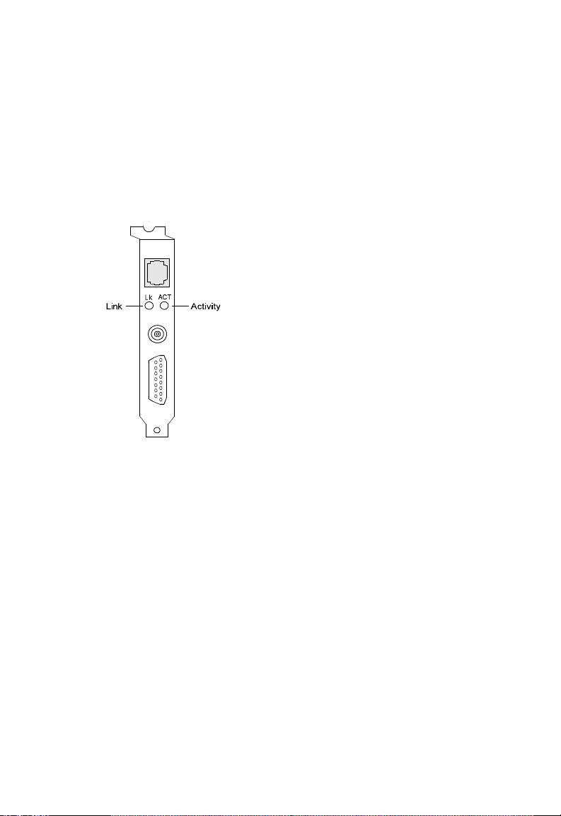
LED Indicators
The cards contain two LEDs for monitoring network conditions.
The function of each LED is described below. Refer to the following figure for the LED location.
INTRODUCTION
Figure 1-2. LED Indicators
Link Status (Lk)
Color: Green
Function: Twisted-pair link status indicator
When lit, this LED indicates an active connection between the
network card and a 10BASE-T hub or switch.
Note: The Link Status LED does not monitor the condition of
the BNC and AUI connections. When the card is configured for these connections, this LED is always lit.
1-3
Page 11

INTRODUCTION
Activity Status (ACT)
Color: Green
Function: Network activity indicator
This LED is unlit upon power on. It lights up to indicate the
presence of network activity on the port. The rate of flashing is
proportional to the amount of network traffic.
1-4
Page 12

CHAPTER 2
INSTALLING THE CARD
The procedure for installing the EZ Card 10 PCI models appears
below. Although instructions for installing the software drivers
are not included here, some related information is provided.
1. Power off your PC and remove its cover.
Please refer to your computer's Installation Manual for
instructions on how to remove the cover.
2. Select an available expansion slot and plug in the card.
The card provides a 32-bit bus interface. It plugs into any
available PCI expansion bus slot. Remove the protector
bracket from the slot you selected. Insert the card into the
slot. Carefully press on the card until all the edge connectors are firmly in place inside the slot. Screw the card's steel
bracket into the PC to secure the connection. Replace the
PC cover.
3. Connect your card to the network.
Select a cable type for your application and attach the card
to the network using the appropriate connector:
• RJ-45 for twisted-pair cable
• BNC for thin coax cable
• AUI for thick coax cable
2-1
Page 13

INSTALLING THE CARD
4. Power on the PC.
Hardware installation has been completed. Switch on power
to the PC.
Note: Your network should be configured automatically by
the PCI computer’s BIOS Setup Program. However,
some manual configuration may be required in older
PCI machines. Refer to “Configuring the Card in
Older PCI Computers” in Appendix C for related
information.
5. Run the Diagnostic program to check the card's hardware installation.
For related topics, see “Running the Setup Program” in
Appendix C.
Caution! Be sure to run this program before installing the
appropriate driver. Otherwise, your PC will hang.
6. Install the driver.
The driver diskette contains all the driver programs supported
by these cards. Refer to the RELEASE.TXT file in the root
directory for a listing of these programs. The drivers for
different network operating systems are contained in separate subdirectories. Refer to the Readme text file in each
subdirectory for instructions on driver installation.
2-2
Page 14

APPENDIX A
SPECIFICATIONS
General
Network Interface
RJ-45 (UTP Cable: EIA/TIA Categories 3, 4, 5)
BNC (Coax Cable: RG-58 A/U or RG-58 C/U)
AUI (Drop Cable)
Standards Supported
IEEE 802.3 and ISO/IEC 8802-3 10BASE-T (twisted-pair),
10BASE2 (thin coax) and 10BASE5 (thick coax)
PCI Local Bus Specification
Rev. 2.0 or later
Hardware Compatibility
PCI local bus-compliant PCs
Data Bus Width
32-bit
I/O Address
Automatically determined based on configuration space
Interrupt
INT A on PCI slot pin assignment,
mapped to the BIOS IRQ setup
A-1
Page 15

SPECIFICATIONS
Operating Environment
Power Requirements
On-board 10BASE-T transceiver (RJ-45)
Stand-by: +5 V / 0.025 A
Transmit: +5 V / 0.073 A
On-board 10BASE2 transceiver (BNC)
Stand-by: +5 V / 0.300 A
Transmit: +5 V / 0.410 A
External 10BASE5 MAU (AUI)
Maximum: +12 V / 0.5 A
Temperature
0° to 55° C (32° to 131° F)
Humidity
10% to 90% (non-condensing)
Size
4.84 in. x 3.86 in. (122.91 mm x 98.18 mm)
EMC/Safety Compliances
FCC Class B
CDOC Class B
CISPR 22:1985 Class B
EN55022:1987 Class B
AS/NZS (1992)
VCCI Class B
EN55022(1988)/CISPR-22(1985)
prEN55024-2(1990)/IE801-2(1991)
prEN55024-3(1991)/IE801-3(1984)
prEN55024-4(1992)/IE801-4(1988)
EN60950
CE marking
A-2
Page 16

Network Drivers
ODI drivers
NetWare 3.x, 4.x
NetWare LAN WorkPlace TCP/IP
Novell LAN Analyzer for NetWare
NDIS/2 drivers
Microsoft LAN Manager V2.x
Windows for Workgroups
IBM LAN Server
LAN Support
IBM OS/2 EE V2.0
DEC PATHWORKS
Lantastic 6.0
Sun PC-NFS
Banyan VINES
IBM TCP/IP for DOS & OS/2
Wollongong Pathway Access
NDIS/3 drivers
Microsoft Windows NT 3.51, 4.0
Windows for Workgroups
Windows 95
Packet drivers
FTP TCP/IP
NCSA TCP/IP
Unix drivers
SCO OpenServer 5.x
SPECIFICATIONS
A-3
Page 17

APPENDIX B
PIN ASSIGNMENTS
RJ-45 Connector
Pin Number Assignment
1 Output Transmit Data +
2 Output Transmit Data 3 Input Receive Data +
6 Input Receive Data -
4, 5, 7, 8 Reserved for other use
Table B.1. RJ-45 Connector Pin Assignments
B-1
Page 18

PIN ASSIGNMENTS
AUI Connector
AUI Pin Assignments
Pin Circuit Signal Name
3 DO-A Data Out Circuit A
10 DO-B Data Out Circuit B
11 DO-S Data Out Circuit Shield
5 DI-A Data In Circuit A
12 DI-B Data In Circuit B
4 DI-S Data In Circuit Shield
8 CO-S Control Out Circuit Shield
2 CI-A Control In Circuit A
9 CI-B Control In Circuit B
1 CI-S Control In Circuit Shield
6 Vc Voltage Common
13 VP Voltage Plus
14 VS Voltage Shield
Shell PG Protective Ground
(Conductive Shell)
Table B.2. AUI Connector Pin Assignments
Note: Voltage Plus (VP) and Voltage Common (Vc) use a
single twisted-pair in the AUI cable.
B-2
Page 19

APPENDIX C
CONFIGURATION
AND DIAGNOSTICS
The driver diskette contains the Setup program (SETUP.EXE).
This program allows you to:
• View the current configuration of the card
• Set up a new configuration
• Run diagnostics
These tasks are described in this chapter.
C-1
Page 20

CONFIGURATION AND DIAGNOSTICS
Running the Setup Program
Insert the driver diskette in your floppy drive. The SETUP program is in the \SETUP subdirectory on this diskette. Change to
the appropriate subdirectory location, type the following command and press <Enter>:
A:\SETUP>SETUP
This will initiate the menu-driven SETUP program and display
the Main Menu as shown below:
Figure C-1. Main Menu
C-2
Page 21

CONFIGURATION AND DIAGNOSTICS
Viewing the Current Configuration
Select this option to view the current settings for your network
card, as shown below.
If you need to modify the current configuration, return to the
Main Menu and select “Set Up New Configuration.”
Figure C-2. Current Configuration Display
C-3
Page 22

CONFIGURATION AND DIAGNOSTICS
Setting Up a New Configuration
If your computer complies with PCI BIOS standards, the system
will automatically allocate the necessary I/O, IRQ and boot ROM
address resources to the card. Although the SETUP program
will not allow you to change the resources which are allocated
by the PCI BIOS, it will allow you to change the following
settings to suit your requirements:
• Media type
• Full-duplex mode
• Boot ROM size
Figure C-3. Set Up New Configuration Menu
C-4
Page 23

CONFIGURATION AND DIAGNOSTICS
Media T ype
The transceiver setting should agree with the network cabling
type. The program provides two choices:
• Auto detection
• 10BASE5 (AUI)
With the first choice, the card automatically detects the connec-
tor in use — either RJ-45 or BNC. The second choice enables
the AUI connector.
Full-Duplex Mode
Enable full-duplex mode only if the card is connected directly to
a switch that also supports this mode. Do not enable this mode
if the card is connected to a hub.
Boot ROM Size
Each card provides an empty socket for an optional 16 KB boot
ROM. Once installed and enabled, the boot ROM permits the
host PC to download the disk operating system (DOS) or
network drivers over the network. The boot ROM function is
disabled by default. After you install a boot ROM, be sure to
enable this function.
C-5
Page 24

CONFIGURATION AND DIAGNOSTICS
Running the Diagnostics
To test the card's components and installation, the SETUP program runs three different tests on the card and corresponding
cabling system as listed below:
• EEPROM Test
• Diagnostics on Board
• Diagnostics on Network
Note: Run the diagnostics before the network driver is loaded
into the system. Otherwise, your system may hang.
EEPROM Test
Read tests are performed on each register in the EEPROM.
Testing the Card
This test monitors the card and corresponding cabling system.
However, it does not test the network's condition.
Figure C-4. On-Board Diagnostics Display
C-6
Page 25

CONFIGURATION AND DIAGNOSTICS
This test actually performs five separate tests:
• Configuration Test — checks the initial status of the Ethernet
controller
• I/O Registers Test — checks I/O accessibility
• Internal Loop Back Test — checks the card's controller
• External Loop Back Test — checks the network link
• RAM Test — checks the condition of the on-board RAM
The screen displays the PASSED or FAILED count for each test.
If a test fails, press the spacebar to display the reason for the
failure and possible solutions.
Testing the Network Connection
This test verifies the card’s ability to communicate with other
devices on the network. At the start of the test, set up one computer as a Responder and at least one as an Initiator. The
Responder displays the status of communications with each
Initiator on the network, while the Initiator displays the current
Responder and the status of corresponding communications.
Note: Should any of these tests fail, reboot your computer and
run the diagnostics again to see if the problem persists.
C-7
Page 26

CONFIGURATION AND DIAGNOSTICS
Configuring the Card in
Older PCI Computers
The card is configured using the host PCI computer's BIOS
setup program. This is done by changing the computer's BIOS
settings. The procedure to do this and the terminology used
depend on the the BIOS you are using.
For example, if your computer uses the Phoenix BIOS, there is a
Device Select field where you are to input the number of the
PCI slot where the adapter is installed (e.g., Slot 3 Device).
Select “Enabled” for the Enable Device field and assign an IRQ
number (the card's IRQ setting is mapped to the BIOS IRQ
setup of the host PCI computer).
Set the Trigger/Routing field to select the Trigger method by
which the IRQ is assigned or routed to the PCI slot. There are
three types of settings to choose from:
• Level/Auto — This is usually the default. Choosing this
option leaves the assigned IRQ free for other uses if the
installed card does not use it.
• Level/Forced — If you are not able get the PCI card to
work properly, choose this option. This will assign the specified IRQ permanently to the card.
• Edge/Auto — Some PCI cards support this option. Do not
use it with SMC’s EZ Card 10 PCI models.
Notes: These PCI cards can only function with the EMM386.exe
memory manager program, version 4.49 or later. You
can verify the version number by entering “EMM386” at
the DOS prompt.
Do not specify the HIGHSCAN option with the
EMM386.exe statement in your config.sys file or your
system will hang.
If you run MEMMAKER and select Custom Setup, do not
specify “Aggressively scan upper memory,” or it will
C-8
Page 27

CONFIGURATION AND DIAGNOSTICS
automatically insert the HIGHSCAN flag into the
EMM386 command line. This parameter cannot be
manually removed once it is installed; doing so will
cause the extended memory manager to malfunction.
For problems with your BIOS setup, refer to your PC’s user
documentation
C-9
Page 28

APPENDIX D
GLOSSARY
BNC
Connector with a half-twist locking shell typically used for thin
coax cable.
Boot ROM
Read-only memory chip that allows a workstation to communicate with a file server and to read a DOS boot program from
the server.
Bus Topology
Network topological arrangement where only one path exists
between any two nodes, and data transmitted by any node is
concurrently available to all other nodes on the same transmission medium.
Driver
Program that enables the network operating system to communicate with LAN cards.
IEEE 802.3 Standard
Standard developed by the IEEE (Institute of Electrical and
Electronics Engineers) for physical and electrical connections in
local area networks.
Interrupt (IRQ)
Signal that temporarily suspends a program when input or output is required and transfers control to the operating system.
LED
Light emitting diode.
Mbps
Megabits per second.
RJ-45 connector
Most common terminator for twisted-pair cable.
D-1
Page 29

GLOSSARY
Star Topology
Also known as hub topology; topology where wires run
between network nodes and a central wiring hub usually
located in the building's wiring closet.
10BASE-T
IEEE specifications for 10 Mbps Ethernet on twisted-pair cable
(100 Ω UTP). The maximum cable length for a point-to-point
connection is 100 m (328 ft.) and the maximum number of
nodes is 1024.
10BASE2
IEEE specifications for 10 Mbps Ethernet on thin coax cable
(50 Ω RG-58). A cable segment can be up to 185 m (607 ft.)
long and have a maximum of 30 nodes.
10BASE5
IEEE specifications for Ethernet on thick D-type cable.
Topology
Logical or physical arrangement of nodes on a network.
Shielded Twisted-Pair Cable (STP)
Cable composed of two insulated wires twisted together and
covered by a foil or braided shielding to reduce electrical
interference.
PCI Local Bus
Bus designed by Intel that can function independently of the
CPU and that supports a 32-bit data path to the CPU, allowing
the use of a wide range of 32-bit peripherals.
Unshielded Twisted-Pair Cable (UTP)
Cable composed of two insulated wires twisted together to
reduce electrical interference.
D-2
Page 30

INDEX
Symbols
10BASE-T 1-2, 1-3, A-1, A-2,
D-2
10BASE2 1-2, A-1, A-2, D-2
10BASE5 1-2, A-1, A-2, C-5,
D-2
32-bit bus interface 2-1, D-2
A
ACT Status LED 1-4
AUI i, 1-1, 1-2, 1-3, 2-1, A-1,
A-2, C-5
AUI Pin Assignments B-2
B
BNC i, ii, 1-1, 1-2, 1-4, A-1,
A-2, C-5, D-1
Boot ROM 1-1, D-1
Boot ROM Size C-4, C-5
C
Configuration 1-1, 2-2, A-1,
C-1
D
Diagnostic Software 2-2
Diagnostics C-1, C-6
Driver Diskette ii, 2-2, B-2
Drivers 2-1, 2-2, A-3, C-4
E
Edge/Auto C-8
EEPROM Test C-6
EMC/Safety Compliances A-2
EMM386.Exe C-8
F
Features 1-1
Full-duplex 1-1, C-4, C-5
H
Hardware Description 1-2
HighScan C-8, C-9
I
I/O Registers C-7
IEEE 802.3 1-1, 1-2, A-1, D-1
Installation 2-1
Introduction 1-1
L
LAN Connectors 1-1, 1-2
LED Indicators 1-3
Level/Auto C-8
Level/Forced C-8
Link Status LED 1-3
Loop Back Test C-7
M
Media Type C-4
N
NE2000 driver 1-1
Network drivers A-3
O
Operating Environment A-2
P
Package contents ii
PCI BIOS C-4, C-8
PCI Local Bus 1-1, A-1, D-2
I-1
Page 31

INDEX
R
RAM Test C-7
Registration Card ii
RELEASE.TXT 2-2
RJ-45 i, 1-1, 1-2, 2-1, A-1,
A-2, C-5, D-1
RJ-45 Pin Assignments B-1
Running Setup C-2
S
Setting up a new configuration
C-4
SETUP.EXE C-1, C-2
Specifications A-1
T
Thick coax cable 1-1, 1-2,
2-1, A-1
Thin coax cable 1-1, 1-2, 2-1,
A-1, D-1
Trigger method C-8
Twisted-pair cable 1-1, 1-2,
2-1, A-1, D-2
V
Viewing the current
configuration C-2
I-2
Page 32

Limited Warranty
HARDWARE: Standard Microsystems Corporation (“SMC”) warrants the EZ Card
10 PCI network cards to be free from defects in workmanship and materials,
under normal use and service, for the following length of time from the date of
purchase from SMC or its Authorized Reseller:
EZ Card 10 PCI Network Cards . . . . . . . . . . . . . . . . . . . . . . .Limited Lifetime
If a product does not operate as warranted during the applicable warranty
period, SMC shall, at its option and expense, repair the defective product or
part, deliver to Customer an equivalent product or part to replace the defective
item, or refund to customer the purchase price paid for the defective product.
All products that are replaced will become the property of SMC. Replacement
products may be new or reconditioned. Any replaced or repaired product or
part has a ninety (90) day warranty or the remainder of the initial warranty
period, whichever is longer.
SMC shall not be responsible for any custom software or firmware, configuration information, or memory data of Customer contained in, stored on, or
integrated with any products returned to SMC pursuant to any warranty.
SOFTWARE: SMC warrants that the software programs licensed from it will
perform in substantial conformance to the program specifications for a period
of ninety (90) days from the date of purchase from SMC or its Authorized
Reseller. SMC warrants the magnetic media containing software against failure
during the warranty period. No updates are provided. SMC’s sole obligation
hereunder shall be (at SMC’s discretion) to refund the purchase price paid by
Customer for any defective software products or to replace any defective media
with software which substantially conforms to SMC’s applicable published specifications. Customer assumes responsibility for the selection of the appropriate
applications program and associated reference materials. SMC makes no warranty that its software products will work in combination with any hardware or
applications software products provided by third parties, that the operation of
the software products will be uninterrupted or error free, or that all defects in
the software products will be corrected. For any third party products listed in
the SMC software product documentation or specifications as being compatible,
SMC will make reasonable efforts to prove compatibility, except where the
non-compatibility is caused by a “bug” or defect in the third party’s product.
STANDARD WARRANTY SERVICE: Standard warranty service for hardware
products may be obtained by delivering the defective product, accompanied
by a copy of the dated proof of purchase, to SMC’s Service Center or to an
Authorized SMC Service Center during the applicable warranty period. Standard
warranty service for software products may be obtained by telephoning SMC’s
Service Center or an Authorized SMC Service Center, within the warranty
period. Products returned to SMC’s Service Center must be pre-authorized by
Page 33

LIMITED WARRANTY
SMC with a Return Material Authorization (RMA) number marked on the outside of the package, and sent prepaid, insured, and packaged appropriately for
safe shipment. The repaired or replaced item will be shipped to Customer, at
SMC’s expense, not later than thirty (30) days after receipt by SMC.
WARRANTIES EXCLUSIVE: IF AN SMC PRODUCT DOES NOT OPERATE AS
WARRANTED ABOVE, CUSTOMER’S SOLE REMEDY SHALL BE REPAIR,
REPLACEMENT OR REFUND OF THE PURCHASE PRICE PAID, AT SMC’S
OPTION. THE FOREGOING WARRANTIES AND REMEDIES ARE EXCLUSIVE
AND ARE IN LIEU OF ALL OTHER WARRANTIES OR CONDITIONS, EXPRESS
OR IMPLIED, EITHER IN FACT OR BY OPERATION OF LAW, STATUTORY OR
OTHERWISE, INCLUDING WARRANTIES OR CONDITIONS OF MERCHANTABILITY AND FITNESS FOR A PARTICULAR PURPOSE. SMC NEITHER
ASSUMES NOR AUTHORIZES ANY OTHER PERSON TO ASSUME FOR IT ANY
OTHER LIABILITY IN CONNECTION WITH THE SALE, INSTALLATION, MAINTENANCE OR USE OF ITS PRODUCTS.
SMC SHALL NOT BE LIABLE UNDER THIS WARRANTY IF ITS TESTING AND
EXAMINATION DISCLOSE THE ALLEGED DEFECT IN THE PRODUCT DOES
NOT EXIST OR WAS CAUSED BY CUSTOMER’S OR ANY THIRD PERSON’S
MISUSE, NEGLECT, IMPROPER INSTALLATION OR TESTING, UNAUTHORIZED
ATTEMPTS TO REPAIR, OR ANY OTHER CAUSE BEYOND THE RANGE OF
THE INTENDED USE, OR BY ACCIDENT, FIRE, LIGHTNING, OR OTHER
HAZARD.
LIMITATION OF LIABILITY: IN NO EVENT, WHETHER BASED IN CONTRACT
OR TORT (INCLUDING NEGLIGENCE) SHALL SMC BE LIABLE FOR INCIDENTAL, CONSEQUENTIAL, INDIRECT, SPECIAL, OR PUNITIVE DAMAGES OF
ANY KIND, OR FOR LOSS OF REVENUE, LOSS OF BUSINESS, OR OTHER
FINANCIAL LOSS ARISING OUT OF OR IN CONNECTION WITH THE SALE,
INSTALLATION, MAINTENANCE, USE, PERFORMANCE, FAILURE, OR INTERRUPTION OF ITS PRODUCTS, EVEN IF SMC OR ITS AUTHORIZED RESELLER
HAS BEEN ADVISED OF THE POSSIBILITY OF SUCH DAMAGES. NOTHING
HEREIN SHALL HAVE THE EFFECT OF LIMITING OR EXCLUDING SMC’S
LIABILITY FOR DEATH OR PERSONAL INJURY CAUSED BY NEGLIGENCE.
Some states do not allow the exclusion of implied warranties or the limitation
of incidental or consequential damages for consumer products, so the above
limitations and exclusions may not apply to you. This warranty gives you specific legal rights which may vary from state to state. Nothing in this warranty
shall be taken to affect your statutory rights.
Standard Microsystems Corporation
80 Arkay Drive
Hauppauge, NY 11788
516-273-3100
Page 34

COMPLIANCES
FCC Class B
This equipment has been tested and found to comply with the limits
for a Class B digital device, pursuant to Part 15 of the FCC Rules.
These limits are designed to provide reasonable protection against
harmful interference in a residential installation. This equipment
generates, uses and can radiate radio frequency energy and, if not
installed and used in accordance with instructions, may cause harmful
interference to radio communications. However, there is no guarantee
that the interference will not occur in a particular installation. If this
equipment does cause harmful interference to radio or television reception, which can be determined by turning the equipment off and on,
the user is encouraged to try to correct the interference by one or more
of the following measures:
• Reorient the receiving antenna
• Increase the separation between the equipment and receiver
• Connect the equipment into an outlet on a circuit different from
that to which the receiver is connected
• Consult the dealer or an experienced radio/TV technician for help
Shielded twisted-pair cable is required for Class B compliance. If
unshielded twisted-pair cable is used, the unit will comply only with
Class A requirements.
CDOC Class B
This digital apparatus does not exceed the Class B limits for radio noise
emissions from digital apparatus set out in the Radio Interference
Regulations of the Canadian Department of Communications.
Shielded twisted-pair cable is required for Class B compliance. If
unshielded twisted-pair cable is used, the unit will comply only with
Class A requirements.
Le présent appareil numérique n’émet pas de bruits radio-électriques
dépassant les limites applicables aux appareils numériques de la classe
B prescrites dens le Règlement sur le brouillage radioélectrique édicté
par le ministère des Communications du Canada.
Une paire torsadée blindée est nécessaire pour l’homologation de
classe B. Si une paire torsadée non blindée est utilisée, le dispositif sera
conforme aux normes de classe A seulement.
Page 35

COMPLIANCES
EC Conformity
This information technology product was found to comply with EC
General Directives 89/336/EEC and 73/23/EEC.
European Headquarters:
Standard Microsystems (Europe) Limited
1st Floor, Pyramid House, Easthampstead Road
Bracknell, Berkshire RG12 1NS, United Kingdom
Compliance with the applicable regulations is dependent upon the
use of shielded twisted-pair cables.
VCCI Class B
Australia AS/NZS 3548 (1992)
SMC contact for products in Australia is:
SMC Australia Pty. Ltd., ACN 069 351 613
LVL 66 MLC Center
Martin Place
Sydney NSW 2000
Phone: 61-2-9238-2206
Fax: 61-2-9238-2220
Page 36

FOR TECHNICAL SUPPORT, CALL:
From U.S.A. and Canada (8:30 AM - 8:00 PM Eastern Time)
(800) SMC-4-YOU; (516) 435-6250; (516) 434-9314 (Fax)
From Europe (8:00 AM - 5:30 PM UK Greenwich Mean Time)
44 (0) 1344-420068; 44 (0) 1344-418835 (Fax)
Bulletin Board Services (BBS)
Modem settings: 9600,8,n,1
New York: (516) 434-3162 (connect speed up to 14,400)
Germany: 49 (0) 89 92861-240
France: 33 (1) 39.73.57.00
United Kingdom: 44 (0) 1344 418838
INTERNET address is: techsupport@smc.com
Driver updates available from the Internet:
Host name info.smc.com (IP address: 170.129.51.1)
SMC Forum on CompuServe: at the prompt (!) type: GO SMC.
World Wide Web: http://www.smc.com/
FOR LITERA TURE OR ADVERTISING RESPONSE, CALL:
U.S.A. and Canada: (800) SMC-4-YOU; Fax (516) 273-1803
New York: (516) 435-6000; Fax (516) 273-1803
Latin America: (630) 916-7007 (630) 916-6304
France: 33 (1) 30.87.42.42; Fax 33 (1) 30.61.41.34
Europe: 44 (0) 1344 418800; Fax 44 (0) 1344 418828
Northern Europe: 44 (0) 1344 418820; Fax 44 (0) 1344 418826
Central Europe: 49 (0) 89 92861-0; Fax 49 (0) 89 92861-230
Eastern Europe/Middle East: 49 (0) 89 92861-142; Fax 49 (0) 89 9101934
Australia (Sydney): 61.2.9238.2206; Fax 61.2.9238.2220
Australia (Melbourne): 61.3.9653.9461; Fax 61.3.9653.9548
South Africa: 27 (0) 11 784-0414; Fax 27 (0) 11 784-0363
Asia Pacific: (65) 336 1800; Fax (65) 339 6625
South Asia: (65) 336 1800; Fax (65) 336 3955
Japan: 81 (3) 57212271; Fax 81 (3) 57212270
EliteFax (SMC's Fax-on-Demand System):
U.S.A. and Canada: (800) SMC-8329
Elsewhere: (516) 435-6107
Publication Number: 79-000559-000
Printed on recycled paper.
 Loading...