


Operations/Service Manual
VULCAN™ Generator
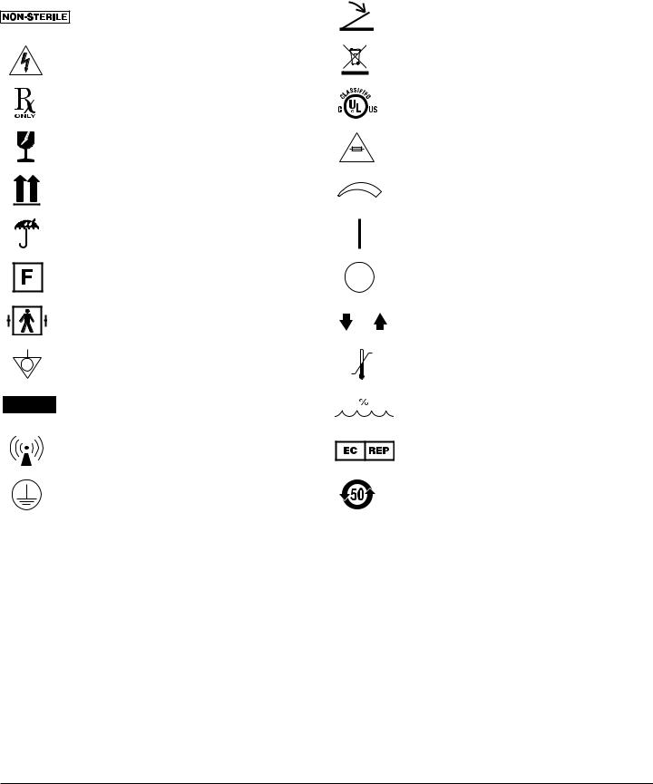
Glossary of Symbols
Non-Sterile
Dangerous Voltage:
Danger of electric shock
CAUTION: U.S. Federal law restricts this device to sale by or on the order of a physician.
Fragile; handle with care
This Way Up
Keep Dry
Neutral (Return) Electrode
Connector
(Split Grounding Pad)
Defibrillator Proof Type
BF Equipment
Equipotentiality
Alternating Current
Non-ionizing Electromagnetic Radiation
Protective Earth (ground)
Footswitch
EU: Not for general waste
UL Classification
Fuse
Amplitude Control
ON
OFF
Up and Down Buttons
Temperature Range
Humidity
European Representative
Service lifetime in years
VULCAN™ Generator Operations/Service Manual |
1061526 Rev. C |
|

Preface / Table of Contents
Preface
This manual provides the information required to operate and maintain the Smith & Nephew VULCAN™ Generator. It is essential that all the information in this manual and on the generator label is read and understood before using or maintaining the equipment.
Table of Contents
Glossary of Symbols.. . . . . . . . . . . . . . . . . . . . . . . . . . . . . . . . . .3 Preface . . . . . . . . . . . . . . . . . . . . . . . . . . . . . . . . . . . . . . . . . . . . .4 Introduction . . . . . . . . . . . . . . . . . . . . . . . . . . . . . . . . . . . . . . . . .5 Device Description. . . . . . . . . . . . . . . . . . . . . . . . . . . . . . . . . . . .5 Indications for Use . . . . . . . . . . . . . . . . . . . . . . . . . . . . . . . . . . . .5 Contraindications. . . . . . . . . . . . . . . . . . . . . . . . . . . . . . . . . . . . .5 Warnings. . . . . . . . . . . . . . . . . . . . . . . . . . . . . . . . . . . . . . . . . . 5-6 Precautions.. . . . . . . . . . . . . . . . . . . . . . . . . . . . . . . . . . . . . . . . .7 Unpacking and General Inspection . . . . . . . . . . . . . . . . . . . . . . .7 Front Panel Layout. . . . . . . . . . . . . . . . . . . . . . . . . . . . . . . . . .8–9 Rear Panel Layout. . . . . . . . . . . . . . . . . . . . . . . . . . . . . . . . . . . . 10 Preoperative Setup.. . . . . . . . . . . . . . . . . . . . . . . . . . . . . . . . . . 11 Operational Modes.. . . . . . . . . . . . . . . . . . . . . . . . . . . . . . . . . . 12 Power Delivery Modes . . . . . . . . . . . . . . . . . . . . . . . . . . . . . . . . 12 Controls and Functions.. . . . . . . . . . . . . . . . . . . . . . . . . . . . 13–14 Instructions for Use.. .. .. .. .. .. .. .. .. .. .. .. .. .. .. .. .. .. .. .. .. .. .. .. .. .. .. .. .. .. .. 14–15 Cleaning and Sterilization. . . . . . . . . . . . . . . . . . . . . . . . . . .15-16 Service and Maintenance.. . . . . . . . . . . . . . . . . . . . . . . . . . .16-17
Service Philosophy. . . . . . . . . . . . . . . . . 16 Replacing Fuses. . . . . . . . . . . . . . . . . . 16 Software Upgrades . . . . . . . . . . . . . . . . 17 Replacing/Returning Worn or Defective
Equipment or Parts. . . . . . . . . . . . . . . . . . . . . . . . . . . . . . . . 17 Preventative Maintenance. . . . . . . . . . . . . . 17 Calibration of Temperature Measurement Circuit . . . . . 17
Troubleshooting . . . . . . . . . . . . . . . . . . . . . . . . . . . . . . . . . . 18-24
Generator Control Unit. . . . . . . . . . . . . . . 18 Alarm and Fault Messages . . . . . . . . . . . . 18–21 Observed Problems. . . . . . . . . . . . . . .22–24
Technical Specifications.. . . . . . . . . . . . . . . . . . . . . . . . . . . . . .25 Ordering Information . . . . . . . . . . . . . . . . . . . . . . . . . . . . . . . . .26 Output Charts.. . . . . . . . . . . . . . . . . . . . . . . . . . . . . . . . . . . 27-28
Output Voltage vs. Output Control. . . . . . . . . . . 27 Power Output vs. Output Control, Cut Mode. . . . . . . 27 Power Output vs. Output Control, Coag Mode. . . . . . 28 Power Output vs. Load Resistance . . . . . . . . . . 28
Guidance and Manufacturer’s Declaration . . . . . . . . . . . . . 29-31
Electromagnetic Emissions . . . . . . . . . . . . . 29 Guidance for Separation Distances. . . . . . . . . . 29 Electromagnetic Immunity. . . . . . . . . . . . 30-31
Warranty . . . . . . . . . . . . . . . . . . . . . . . . . . . . . . . . . . . .Back Cover Service Replacement Units Warranty.. . . . . . . . . . . . .Back Cover Service Replacement Program. . . . . . . . . . . . . . . . . . .Back Cover Repair Service Program. . . . . . . . . . . . . . . . . . . . . . . .Back Cover
Figures |
|
|
|
1 |
Control unit front panel. . |
. . . . . . |
. . . . . . . . . 8 |
2 |
Control unit rear panel. . |
. . . . . . |
. . . . . . . . . 10 |
3 |
AC receptacle with fuses. |
. . . . . . . . . . . . |
. . . . . . . . . . . . . . . . . 16 |
|
1061526 Rev. C |
VULCAN™ Generator Operations/Service Manual |

Introduction / Device Description / Indications for Use / Contraindications / Warnings
Introduction
The Smith & Nephew VULCAN™ Generator is designed to provide finely-controlled radiofrequency (RF) energy for the coagulation, cutting, ablation, and hemostasis of soft tissue during a variety of surgical procedures.
The generator control unit is specifically designed for use with Smith & Nephew temperature-controlled and power-controlled probes.
Indications for Use
The Smith & Nephew VULCAN Generator is indicated for general surgical purposes, including orthopedic and arthroscopic applications, for coagulation, ablation, and hemostasis of soft tissues in combination with Smith & Nephew temperaturecontrolled, cutting, and ablation probes.
Device Description
The generator control unit is a line-voltage powered, radiofrequency generator capable of delivering up to 200 watts of power. The generator control unit
includes a neutral electrode monitor (NEM) to monitor split grounding pad contact quality. It is designed to be used only with Smith & Nephew temperaturecontrolled, cutting, and ablation probes and includes the following features:
•Two RF output modes: Temperature Control Mode, where the output power is softwarecontrolled to maintain a specified tissue temperature; and Power Control Mode, used for cutting, ablation, and hemostasis.
•Numerical displays for impedance, set power, delivered power, set temperature, actual temperature, set cut, set coagulation, and preset selections.
•Message display for text messages.
•Indicators for electrode type (monopolar or bipolar), mode (Temperature Control or Power Control), stand-by, RF power on, RF output type (cut or coagulation), fault, and split grounding pad monitoring. NEM monitors the split grounding pad connection during surgery, discontinuing
RF delivery if a fault in the NEM monitor circuit is detected.
•A probe recognition system: the generator control unit automatically selects the appropriate mode and preset settings for the probe type.
The Smith & Nephew VULCAN Generator software can be upgraded at the customer’s location
with a Smith & Nephew supplied PCMCIA card. For information regarding software upgrades, please contact your authorized Smith & Nephew representative.
Contraindications
There are no known absolute contraindications to the use of electrosurgery.
The use of the Smith & Nephew VULCAN Generator and accessories is contraindicated, when, in the judgment of the physician, an electrosurgical procedure would be contrary to the best interest of the patient.
 Warnings
•It is the surgeon’s responsibility to be familiar with the appropriate surgical techniques prior to use of this device..
•Read these instructions completely prior to use..
•DANGER: Risk of explosion if used in the presence of flammable anesthetics, skin preparation agents, or biointestinal gases..
•Hazardous electrical output.. This equipment should be used only by qualified medical personnel trained in the use of electrosurgery devices..
•This device has been tested and verified to comply with the IEC 60601-2-2.. This exceeds the requirements specified by FCC part 18 for ISM equipment.. This device is intended for operation in a medical facility only.. Usage in a residential environment will likely cause unacceptable RF interference for which the user is held responsible..
•The generator control unit must be powered from a properly grounded 120–240 VAC, single-phase supply.. Excessive risk (leakage current) may result if this equipment is connected to other than the manufacturer’s recommended power distribution system..
•Risk of burns or fire.. Do not use near conductive materials such as metal bed parts, inner-spring mattresses, etc..
VULCAN™ Generator Operations/Service Manual |
1061526 Rev. C |

Warnings (continued)
•Check that the electrical equipment is properly grounded (i..e.. plugs contain a ground prong).. The generator control unit must be plugged into a hospital-grade AC outlet..
•Safe use of monopolar electrosurgery demands proper grounding of the patient and proper insulation between the patient and any metal surfaces.. A split pad with a surface area of at least 20 square inches (130 cm2) is required.. Valleylab… REM… pads (REF 7209687)
meet this dimensional requirement and are recommended by Smith & Nephew for use with the VULCAN™ Generator.. Pads with a surface area of less than 20 square inches may have a lower dispersive effect.. It is the responsibility of the user to qualify any alternate ground pad..
•Use of an inadequate ground pad or incorrect placement of the ground pad may result in a burn injury to the patient..
•Improper probe usage may result in patient burns at the return pad.. To avoid this, follow the manufacturer’s Instructions for Use..
•Do not exceed the RF duty cycle for the probe..
•Do not withdraw the probe while energy delivery is activated; this may result in an unintended patient burn or ignition of flammable materials..
•When using RF surgical equipment, keep the working part of the RF probe’s active electrode in the field of view to avoid accidental RF burns.. Avoid contact of the probe with metal parts of the scope and other conductive accessories by ensuring, before activation of the RF probe, that the active electrode is at sufficient distance from the tip of the scope..
•Failure of the radiofrequency surgical equipment could result in unintended increase of output power..
•Burns to the surgeon’s hands may be possible if a probe comes into contact with a metal instrument or surface..
•Use of electrosurgery in patients with internal or external pacemakers, implantable defibrillators or monitoring equipment
may require special considerations.. The attending cardiologist and/or the pacemaker manufacturer should be consulted prior to surgery..
•The operating table should be grounded..
•During monopolar electrosurgery the patient should not come into contact with any metal parts which are grounded or which have appreciable capacitance to earth (operating tables, supports, etc..).. The use of anti-static sheeting is recommended for this purpose..
•During monopolar electrosurgery skin-to-skin contact (i..e.., between the arms and body of the patient) should be avoided.. Insertion of dry gauze or its equivalent is recommended..
•The probe cables and extension cable should be positioned in such a way that contact with the patient or other leads is avoided.. Probes not in use should be stored isolated from the patient..
•Incorrect actual temperature readings may result in improper treatment.. Verify that the TEMPERATURE display reads the expected value (room temperature or body temperature) prior to treatment.. If the TEMPERATURE reading is not accurate, check the device and connectors for damage, moisture, or contamination.. Clean or replace as needed..
•If desired tissue effect is not being achieved, do not increase power beyond the normal range without first inspecting the integrity of the probe and neutral (return) electrode..
•To prevent electric shock, unplug the control unit from the electrical outlet before attempting to replace the fuses..
•To avoid fire hazard, use only fuses of the correct type, voltage rating, and current rating..
•To prevent electric shock, do not remove the control unit cover.. There are no userserviceable components inside.. Dismantling the equipment will void the warranty.. Refer servicing to qualified Smith & Nephew personnel..
1061526 Rev. C |
VULCAN™ Generator Operations/Service Manual |

Precautions / Unpacking and General Inspection
Precautions
U.S. Federal law restricts this device to sale by or 
 on the order of a physician.
•Prior to each use, inspect the device to ensure it is functioning properly and not damaged. Do not use a damaged device.
•The Smith & Nephew VULCAN™ Generator is designed specifically for use only with Smith & Nephew arthroscopic radiofrequency probes. Do not use other devices with the generator control unit.
•Check the probe and extension cable connections for the presence of liquid before use or whenever a probe is connected or disconnected during
a procedure. Liquid may enter the connection during a procedure. ANY liquid can cause the connections to short, resulting in erroneous probe recognition or damage to the probe, cable, or generator control unit.
•Check the generator control unit’s LCD message display to ensure that the proper probe identification and settings are displayed prior to beginning any procedure.
•Use the lowest RF power setting necessary to achieve the desired tissue effect.
•This equipment is designed and tested to minimize interference with other electrical equipment. However, if interference occurs with other equipment it may be corrected by one or more of the following measures:
–Reorient or relocate this equipment, the other equipment, or both.
–Increase the separation between the pieces of equipment.
–Connect the pieces of equipment into different outlets or circuits.
–Consult a biomedical engineer.
•This equipment contains electronic printed circuit assemblies. At the end of the useful life of the equipment it should be disposed of in accordance with any applicable national or institutional related policy relating to obsolete electronic equipment.
•Inspect all components, including extension cables and power cord, regularly for wear. Pay particular attention to extension cable insulation. Replace if evidence of deterioration is noted.
•Apparent low output or failure of the generator control unit to function properly at normal operating settings may indicate faulty application of the split grounding pad.
•When the generator control unit is used simultaneously with physiological monitoring equipment on the same patient, any monitoring electrodes should be placed as far from the surgical electrodes as possible. Needle monitoring electrodes are not recommended. Monitoring systems using high frequency current-limiting devices are recommended.
•Use only the power cord and connector specified for this unit.
•Electrical safety testing should be performed by a biomedical engineer or other qualified person.
•Do not immerse the footswitch cable.
Unpacking and General Inspection
Carefully unpack and inspect all of the components shipped with the Smith & Nephew VULCAN Generator. The following should have been received:
Quantity Description
1Smith & Nephew VULCAN Generator (REF 7210812)
1Smith & Nephew VULCAN Footswitch (REF 7209692)
1Hospital-grade power cord, country-specific
1Smith & Nephew VULCAN Generator Operations/Service Manual (REF 1061526)
The Smith & Nephew VULCAN Extension Cable (REF 7209693) is available as an accessory for use with probes that do not include an integrated cable.
If any parts are missing or damaged, please contact your authorized Smith & Nephew sales
representative. Save the carton and packing materials in the event that a component needs to be returned for repair.
VULCAN™ Generator Operations/Service Manual |
1061526 Rev. C |
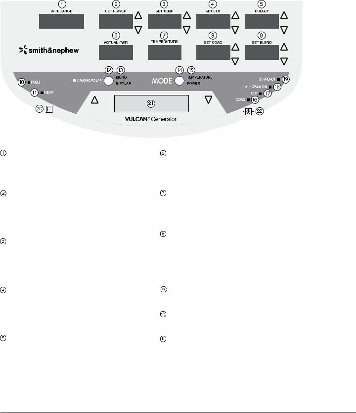
Front Panel Layout
Front Panel Layout
Figure 1. Control unit front panel
IMPEDANCE Display
IMPEDANCE displays the impedance in ohms, measured at the tip of the probe. Active in both
Temperature Control and Power Control Modes.
SET POWER Display with Up/Down Arrows
SET POWER displays the maximum probe power output in watts, increased or decreased using the SET POWER up/down arrows. Active only in
Temperature Control Mode.
SET TEMP Display and Up/Down Arrows
SET TEMP displays the target tissue temperature in degrees Celsius (° C), increased or decreased
using the SET TEMP up/down arrows. Active only in
Temperature Control Mode.
SET CUT Display with Up/Down Arrows
SET CUT displays the maximum probe power output in watts, increased or decreased using the SET CUT up/down arrows. Active only in Power Control Mode and the probe supports adjustment of SET CUT.
PRESET Display with Up/Down Arrows
PRESET displays the preset temperature and/or power combination chosen and is adjustable using the PRESET up/down arrows. Settings are displayed as 1, 2, 3, etc. Active in Temperature Control and Power Control Modes when the probe supports adjustment of PRESET.
ACTUAL PWR Display
ACTUAL PWR displays the actual power in watts delivered to the probe. Active only in Temperature Control Mode.
TEMPERATURE Display
TEMPERATURE displays the actual temperature in degrees Celsius (° C), measured at the tip of the probe. Active only in Temperature Control Mode.
SET COAG Display with Up/Down Arrows
SET COAG displays the maximum probe power output in watts, increased or decreased using the SET COAG up/down arrows. Active only in Power Control Mode and the probe supports adjustment of SET COAG.
SET BLEND Display with Up/Down Arrows
The SET BLEND mode is inactive for all probes.
FAULT Indicator (Red Light)
FAULT illuminates when a fault condition is detected.
NEM Indicator (Green or Red Lights)
NEM illuminates with a green light when the NEM circuit is correctly connected and with a red light when the NEM circuit is incorrectly connected. NEM will only illuminate when a monopolar probe is being used.
1061526 Rev. C |
VULCAN™ Generator Operations/Service Manual |

Front Panel Layout (continued)
BI / MONOPOLAR Button
The BI / MONOPOLAR button selects the appropriate RF energy mode (monopolar or bipolar). The generator selects the appropriate mode automatically based on the probe type.
BI / MONOPOLAR Indicator
Either MONO (monopolar) or BIPOLAR is illuminated to identify the appropriate probe type.
MODE Button
The MODE button selects the appropriate RF energy delivery mode (Temperature Control or Power Control).
MODE Indicator
Either TEMPERATURE (Temperature Control Mode) or POWER (Power Control Mode) is illuminated to identify the appropriate generator mode.
COAG Indicator (Blue Light)
COAG illuminates when the generator control unit is delivering RF power and when the blue COAG (right) footswitch is pressed.
CUT Indicator (Yellow Light)
CUT illuminates when the generator control unit is delivering RF power and when the yellow CUT (left) footswitch is pressed.
RF POWER ON Indicator (Green Light)
RF POWER ON illuminates when the generator control unit is delivering RF power.
STAND-BY Indicator (Green Light)
STAND-BY illuminates when the generator control unit is in Stand-By Mode.
Neutral (Return) Electrode Connector
Accepts a dual–pin connector specifically designed for neutral electrode monitoring (NEM).
Message Display
Displays modes, probe type, alarms, warnings, or fault messages.
Probe Connector
Accepts 8-pin Smith & Nephew temperaturecontrolled, cutting, ablation, and hemostasis probes. The Smith & Nephew VULCAN™ Extension Cable (REF 7209693) may be used with the generator control unit.
VULCAN™ Generator Operations/Service Manual |
1061526 Rev. C |

Rear Panel Layout
Rear Panel Layout
VULCAN™
Generator ∑ Generator ∑ Generador ∑ Générateur ∑ Generatore ∑
Generator ∑ Generator ∑ Gerador ∑ Generator ∑ Generator ∑
OUTPUT POWER |
7210812 |
|
200 W Max. (100–250 U) |
||
|
||
460 kHz |
ZL |
|
|
100–240V~
50/60Hz, 800VA
81013076 Rev. C 01/2008
Figure 2. Control unit rear panel
Footswitch Connector
Accommodates the generator footswitch cable supplied with the Smith & Nephew VULCAN™ Generator.
Volume Control
This knob adjusts the volume of the energy delivery tone.
Fan Outlet
Carrying Handle
Equipotential Compensator Terminal
This terminal can be used to bring other equipment to the same case potential as the generator control unit.
Power Cord Connector
The power cord connector is part of the power input module, and accommodates the hospital-grade power cord supplied with the Smith & Nephew VULCAN Generator.
Fuse Access Door
The fuse access door is part of the power input module. See the “Replacing Fuses” section for instructions on fuse replacement. To avoid hazards, use appropriate fuses as specified in the “Technical Specifications” section.
On/Off Switch
Rocker-type main power switch.
10 |
1061526 Rev. C |
VULCAN™ Generator Operations/Service Manual |
 Loading...